1
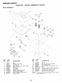
NUMBER 917.256701
OWNER'S
MANUAL
* Assembly
* Operation
* Customer Responsibilities
* Service and Adjustments
* Repair Parts
CAUTION: Read and follow all safety rules and instructions before operating this equipment.
FOR CONSUMER ASSISTANCE HOT LINE, CALL THIS TOLL FREE NUMBER: 1-800-659-5917
/IIIHIII
................................................ !111
SAFETY
RULES
Practices for Ride-On
Safe Operation
Mowers
A
IMPORTANT:
THiS CUTTING MACHINE IS CAPABLE OF AMPUTATING
HANDS AND FEET AND THROWING
OBJECTS.
FAILURE TO OBSERVE THE FOLLOWING SAFETY INSTRUCTIONS
COULD RESULT IN SERIOUS INJURY OR DEATH.
I.
.
•
•
•
=
.
0
.
•
•
,
•
•
•
IlL CHILDREN
GENERAL
OPERATION
Read, understand+ and follow all instructions in the manual
and on the machine before starting.
Only allow responsible adults, who are familiar with the
instructions, to operate the machine.
Clear the area of objects such as rocks, toys, wire, etc.,
which could be picked up and thrown by the btade.
Be sure!he area is dear of other people before mowing. Stop
machine if anyone #nters the area.
Never carry passengers.
Do not mow in reverse unless absolutely necessary. Always
look down and behind before and while backing.
Be aware of the mower discharge direction and do not point
it at anyone. Do not operate the mower without either the
entire grass catcher or the guard in place.
Slow down before turning.
Never leave a running machine unattended. Always turn off
blades, set parking brake, stop engine, and remove keys
before dismounting.
Turn off blades when not mowing.
Stop engine before removing grass catcher or unclogging
chute.
Mow only in daylight or good artificial light.
Do not operate the machine while under the influence of
alcohol or drugs,
Watch for traffic when operating near or crossing roadways.
Use extra care when loading or unloading the machine into
a trailer or truck.
Tragic accidents can occur if the operator is not alert to the
presence of children.
Children are often attracted to the
machine and the mowing activity.
Never assume that
children will remain where you last saw them.
•
Keep children out of the mowing area and under the watchful
care of another responsible adult.
Be alert and turn machine off if children enter the area.
°
Before and when backing, look behind and down for small
children.
=
Never carry children. They may fail off and be seriously
injured or interfere with safe machine operation.
Never atlow children to operate the machine.
Use extra care when approaching blind corners, shrubs,
trees, or other objects that may obscure vision.
•
•
IV. SERVICE
•
Use extra care in handling gasoline and other fuels. They are
flammable and vapors are explosive.
Use only an approved container.
Never remove gas cap or add fuel with the engine
running. Allow engine to cool before refueling. Do not
smoke.
Never refuel the machine indoors.
Never store the machine or fue! container inside where
there is an open flame, such as a water heater.
Never run a machine inside a closed area.
•
•
II.
Keep nuts and bolts, especially blade attachment bolts, tight
and keep equipment in good condition.
Never tamper with safety devices.
Check their proper
operation regularly.
Keep machine free of grass, leaves, or other debris build-up.
Clean oil or fuel spillage. Aliow machine to cooi before
storing.
Stop and inspect the equipment if you strike an object.
Repair, if necessary, before restarting.
Never make adjustments or repairs with the engine running.
Grass catcher components are subject to wear, damage, and
deterioration, which could expose moving parts or atIow
objects to be thrown. Frequently check components and
repiace with manufacturer's recommended parts, when necessary.
Mower blades are sharp and can cut. Wrap the blade(s) or
wear gloves, and use extra caution when servicing them.
Check brake operation frequently.
Adjust and service as
required.
SLOPE OPERATION
•
Slopes are a majQr factor related to toss-of-control
and
tipover accidents; which can result in severe injury or death.
All slopes require extra caution. If you cannot back up the
slope or if you feel uneasy on it, do not mow it.
°
•
DO:
•
Mow up and down stopes, not across.
=
Remove obstacles such as rocks, tree limbs, etc+
=
watch for holes, ruts, or bumps.
Uneven terrain could
overturn the machine. Tall grass can hide obstacles.
•
Use slow speed. Choose a tow gear so that you will not have
to stop or shift while on the slope.
•
Follow the manufacturer's
recommendations
for wheel
weights or counterweights to improve stability,
°
Use extra care with grass catchers or other attachments.
These can change the stability of the machine.
Keep all movement on the slopes slow and gradual Do not
make sudden changes in speed or direction.
=
Avoid starting or stopping on a slope. If tires lose traction,
disengage the blades and proceed slowly straight down the
slope.
•
•
.
•
i
Look for this symbol
A
DO NOT:
•
Do not turn on slopes unless necessary, and then, turn stowly
and gradua y downh !1,if possible.
+
•
Do not mow near drop-effs, ditches, or embankments The
mower could suddenly turn over if a wheel is over the edge
of a cliff or ditch, or if an edge caves in.
°
Do not mow on wet grass. Reduced traction could cause
sliding.
o
Do not try to stabilize the machine by putting your foot on the
ground.
•
Do notuse grass catcher on steep slopes.
to point
CAUTION!!t
ALERT!!! It means
YOUR
portant
safetyBECOME
precautions.
SAFETY IS INVOLVED.
_,_
i
CAUTIONi
A
Out im-
Always
disconnect
i
i
spark plug
spark plug in order to prevent accidental
wire and place wire where it cannot contact
starting when setting up, transporting,
adjusting or making repairs.
ii
A
i,iii, ,i
WARNING
The engine exhaust from this product contains cliemicals known to the State of California to cause cancer, birth defects, or other
reproductive
harm.
2
i
i i,g
PRODUCT
CONGRATULATIONS
on your purchase of a Sears
Tractor. It has been designed, engineered and manufactured to give you the best possible dependability and
performance.
Should you experience any problem you cannot easily
remedy, please contact your nearest Sears Authorized
Service Center/Department.
We have competent, wel!trained technicians and the proper tools to service or repair
this tractor.
Please read and retain this'manual. The instructions will
enable you to assemble and maintain your tractor properly.
Atways observe the "SAFETY RULES".
MODEL
NUMBER
917.256701
SERIAL
NUMBER
SPECIFICATIONS
HORSEPOWER:
t&0
GASOLINE CAPACITY
AND TYPE:
3.5 GALLONS
UNLEADED REGULAR
OIL TYPE (API-SF/SG):
SAE 30 (above 32°F)
SAE 5W-30 (below 32°F)
OIL CAPACITY:
Wi FILTER:
WiO FILTER:
SPARK PLUG:
(GAP: .025")
CHAMPION
RV17YC
VALVE CLEARANCE:
INTAKE:
EXHAUST:
.003" - .006"
.013" - .016"
GROUND SPEED (MPH):
FORWARD:
1st
2nd
3rd
4th
5th
6th
REVERSE:
DATEOFPURCHASE
THE MODEL AND SERIAL NUMBERS WILL BE FOUND
ON A PLATE UNDER THE SEAT.
YOU SHOULD RECORD BOTH SERIAL NUMBER AND
DATE OF PURCHASE AND KEEP IN A SAFE PLACE
FOR FUTURE REFERENCE.
MAINTENANCE
AGREEMENT
A Sears Maintenance
Agreement
uct. Contact your nearest Sears
CUSTOMER
-
Read and observe
the safety
•
Follow a regular schedule
using your tractor.
FRONT:
REAR:
°
Follow the instructions
under "Customer
Responsibilities" and "Storage" sections of this owner's manual.
caring for and
CHARGING SYSTEM:
15 AMPS @ 3600 RPM
BATTERY:
AMPiHR:
MIN. CCA:
CASE SIZE:
BLADE BOLT TORQUE:
30-35 FT. LBS.
30
240
UtR
In the state of California the above is required by law
(Section 4442 of the California Public Resources Code),
Other states may have similar laws. Federal laws apply on
federal lands. A spark arrester for the muffler is available
through your nearest Sears Authorized Service Center/
Department (See REPAIR PARTS section of this manual),
WARNING:
This tractor
is equipped
with an internal
combustion
engine and should not be used on or near any
unimproved
forest-covered,
brush-covered
or grass-covered land unless the engine's exhaust system is equipped
LIMITED TWO YEAR WARRANTY
14 PSI
10 PSi
with a spark arrester meeting applicable local or state laws
(if any). Ira spark arrester is used, it should be maintained
in effective working order by the operator.
rules.
in maintaining,
1.I
1.4
2.3
3.5
4.5
&7
1.8
TIRE PRESSURE:
is available on this prod_
store for details.
RESPONSIBiLITiES
4.0 PINTS
3.5 PINTS
ON CRAFTSMAN
RIDING EQUIPMENT
For two (2) years from the date of purchase, if this Craftsman Riding Equipment is maintained, lubricated and tuned up according
to the instructions in the owner's manual, Sears will repair or replace, free of charge, any parts found to be defective in material or
workmanship.
This Warranty does not cover:
•
Expendable items which become worn during normal use, such as blades, spark plugs, air cleaners, belts, etc.
o
Tire replacement or repair caused by punctures from outside objects, such as nails, thorns, stumps, or glass.
,
Repairs necessary because of operator abuse, negligence, improper storage or accident or the failure to maintain the
equipment according to the instructions contained in the owner's manual.
•
Riding equipment used for commercial or rental purposes.
LIMITED
90 DAY WARRANTY
ON BATTERY
For ninety (90) days from date of purchase, if any battery included with this riding equipment proves defective in material or
workmanship and our testing determines the battery will not hold a charge, Sears will replace the battery at no charge.
IN-HOME WARRANTY SERVICE ON YOUR CRAFTSMAN RIDING EQUIPMENT tS AVAILABLE AT NO-CHARGE FOR 30
DAYS FROM THE DATE OF PURCHASE, PLEASE CONTACT YOUR NEAREST SERVICE CENTER. AFTER 30 DAYS FROM
THE DATE OF PURCHASE, WARRANTY SERVICE IS AVAILABLE BY TAKING YOUR CRAFTSMAN RIDING EQUIPMENT TO
YOUR NEAREST SEARS SERVICE CENTER. (IN-HOME WARRANTY SERVICE WILL STILL BE AVAILABLE AFTER 30 DAYS
FROM THE DATE OF PURCHASE BUT A STANDARD TRIP CHARGE WILL APPLY.) THIS WARRANTY APPLIES ONLY
WHILE THIS PRODUCT lS _NTHE UNITED STATES.
This Warranty give s you specific legal rights, and you may also have other rights which may vary from state to state.
SEARS,
ROEBUCK
AND CO., D/817 WA, HOFFMAN
3
ESTATES,
IL 60179
TABLE OF CONTENTS
MAINTENANCE SCHEDULE .....................................
16
SERVICE AND ADJUSTMENTS ........................... 20-25
STORAGE ...................................................................
26
TROUBLESHOOTING ...........................................
27-28
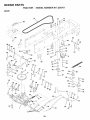
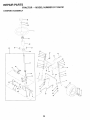
REPAnR PARTS - TRACTOR ................................ 30-47
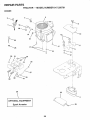
REPAIR PARTS- ENGINE ....................................
48-57
PARTS ORDERINGtSERVtCE ............... BACK COVER
SAFETY RULES ............. ;..............................................
2
PRODUCT
SPECIFICATIONS
......................................
3
CUSTOMER
RESPONSiBILITiES
......................
3, 16-19
WARRANTY
..................................................................
3
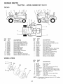
TRACTOR
ACCESSORIES
..........................................
5
ASSEMBLY
.............................................................
7-10
OPERATION
..........................................................
11-15
INDEX
A
Accessories ...........................................
5
Adjustments:
Brake ............................................
23
Carburetor ....................................
25
Mowe
Front-To-Back ......................... 21
Side-To-Side ........................... 20
Throttle Control Cable .................. 25
Air Filter, Engine .................... .............. !8
Air Screen, Engine .............................. 19
Assembly ..........................................
7-10
B
Battery:
Charging ........................................
Cleaning .......................................
Starting with Weak Battery ..........
Storage ........................................
Terminals .....................................
Belt:
Motion Drive
Remova!iRepiacement
...........
Mower Belt(s)
Removal/Replacement
...........
Blade:
Sharpening ..................................
Replacement ................................
BrakeAdjustment
................................
8
17
24
26
t6
Engine:
Air Filter ........................................
18
Air Screen ....................................
!9
Cooling Fins ................................. t 8
Oil Change ................................... 18
Oil Level .......................................
14
Oit Type ...................................
14, t 8
Preparation ..................................
14
Repair Parts ............................ 48-57
Starting .........................................
15
Storage ........................................
26
F
14
26
24
Safety Rules ..........................................
Seat .......................................................
.................. 24
23
L
I7
17
22
Leveling Mower Deck ..........................
Lubrication:
Chart ............................................
Engine ..........................................
20
t6
18
M
C
Carburetor Adjustment ........................ 25
Controls, Tractor .................................
11
Customer Responsibilities ............. 16-19
Engine:
Air Filter ....................................
t8
Air Screen ................................. 18
Coofing Fins ............................. 18
Engine Oil ........................... 14,18
Fuel Filter .................................
tg
Spark Plug(s) ........................... 19
Tractor;
Battery ......................................
17
Blade ........................................
17
Lubrication Chart ..................... t 6
Maintenance Schedule ............ 16
Tire Care .......................... 8,17,23
Transaxle .................................
18
Cutting Height, Mower ........................
18
t9
Repair Parts ...................................
H
22
13
E
P
Parking Brake ................................ 12-13
Parts Bag ..............................................
6
Parts, Replacement/Repair
............ 30-47
Product Specifications ..........................
3
R
Filter:
Air Filter ............. i....: .....................
Fuel ..............................................
Fue!:
Type .............................................
Storage ........................................
Fuse ....................................................
Hood Removal/Installation
Operating Mower ................................
!4
Options:
Accessories ....................................
5
Spark Arrester ........................... 3,38
Maintenance Schedule .......................
Mower:
Adjustment, Front-to-Back ...........
Adjustment, Side-to-Side .............
Blade Replacement .....................
Blade Sharpening ........................
Cutting Height ..............................
Installation ....................................
Operation .....................................
Removal .......................................
16
21
20
17
17
t3
20
!4
20
Mowing Tips ........................................
15
Muffler .................................................
t9
Spark Arrester ........................... 3,38
O
Oil:
30-47
S
2
8
Service and Adjustments ............... 20-25
Carburetor ..... :.............................. 25
Fuse ............................................
: 24
Hood Removal/Installation ........... 24
Motion Drive Belt
RemovaliRepJacement
........... 23
Mower Belt(s)
Removal/Replacement
........... 22
Mower Adjustment
Front-to-Back .......................... 21
Side-to-Side .............. ._............. 20
Mower Removaltlnstatlation ......... 20
Tire Care .............................. 8,17,23
Slope Guide Sheet .............................. 59
Spark Piug(s) ......................................
I9
Specifications. .......................................
3
Starting the Engine ........................ 14-15
Steering Wheel ................................ 7,23
Stopping the Tractor ........................... 13
Storage ................................................
26
T
Throttle Control Cable Adjustment ....... 25
Tires ............................................
8,17,23
Troubleshooting Chart ................... 27-28
Transaxle ............................................
18
W
Cold Weather Conditions ........ 14,18
Engine ..........................................
18
Storage ........................................
26
Operatiori .......................................
1t-15
Electrical:
Interlocks and Relays .................. 24
Schematic ....................................
29
Wiring Diagram ............................ 30
4
Warranty ................................................
Wiring Diagram ...................................
Wiring Schematic ................................
3
30
29
ACCESSORIES
i i ,ll,lll,,l_,,i,
AN
i i,i
,in,m
ATTACHMENTS
ii1,1 HII,I,
.................
These accessories and attachments were available through most Sears retail outlets and service centers when the tractor was purchased.
Most Sears stores can order these items for you when you provide the model number of your tractor,
ENGINE
SPARK PLUG
MAINTENANCE
GAS CAN
ENGINE OIL
FUEL STABILIZER
AIR FILTER
BLADES
BELTS
%
PERFORMANCE
Sears offers a wide variety of attachments that fit your tractor. Many of these are listed below with brief explanations of how they can he{p
you. This list was current at the time of publication; however, it may change in future years - more attachments may be added, changes
may be made in these attachments, or some may no longer be availab{e or fit your model. Contact your nearest Sears store for the
accessories
and attachments
that are available for your tractor,
Most of these attachments do not require additional hitches or conversion kits (those that do are indicated) and are designed for easy
attaching and detaching.
AERATOR promotes deep root growth for a healthy lawn. Tapered 2.5..inch steel spikes mounted on t 0-inch diameter discs
puncture holes in soil at close intervals to let moisture soak in.
Steel weight tray for increased penetration.
BAGGER lets you cotlect grass clippings and leaves for a
healthier, heater looking Iawn. Two Permanex containers hoid
30-gallon plastic bags,
BUMPER protects _front end of tractor from damage.
CARTS make hauling easy. Variety of sizes available, plus
accessories such as side panel kits, toot caddy, cart cover,
protective mat and doily.
SNOW BLADE forsnow removal only. 14-inch high, 48-inch wide
biadectears42-inchpathwhenangled_eftorright.
Raises, lowers
with side lever. Adjustable skids; replaceable, reversible scraper
bar. (Use with tire chains and wheel weights and/or rear drawbar
weight.)
SNOWTHROWER has 40-inch swath. Drum-type auger handles
powdery andwet/heavy
snow. Mounts easily with simple pin
arrangement. Discharge chute adjusts from tractor seat. 6-inch
diameter spout discharges snow !0 to 50 feet. Lift controiled at
tractor seat. (Use with chains and wheel weights and/or rear
drawbar weight.)
SPRAYERS use 12-vott DC electric motor that connects to the
tractor battery or other 12-volt source,
includes booms for
automatic spraying and hand held wand for spot spraying. Wand
has adjustable spray pattern. For applying herbicides, insecticides, fungicides and liquid fertilizers.
SPREADERiSEEDERS
make seeding, fertilizing, and weed killing easy. Broadcast spreaders are also useful for granular deicers and sand.
CORING AERATOR takes small p{ugs out of soil to a!low moisture and nutrients to reach grass roots. 36-inch swath, 24
hardened steel coring tips. 150 lb. capacity weight tray.
EASY OIL DRAIN VALVE rnakes oil changes easier, faster.
FRONT NOSE ROLLER canters in.frontof mower deck to reduce
chances of "scalping" on uneven terrain.
GANG HITCH lets you tow 2 or 3 pull-behind attachments at once,
such as sweepers, dethatchers, aerators (not for use with rotlers,
carts or other heavy attachments),
GAUGE WHEELS on both sides of the mower deck reduce
chances of"scalping" on uneven terrain. For mower decks not so
equipped.
MULCH RAKF-JDETHATCHER loosens soil and flips thatch and
matted leaves to lawn surface for easy pickup. Twenty spring tine
teeth. Useful to prepare bare areas for seeding. Available for front
or rear mounting.
HIGH PERFORMANCE
REEL-ACTION
SPRING TINE DETHATCHER covers 36-inch wide path and
tosses thatch into large hopper. Mounts behind tractor.
MULCHING CLOSE-OUT PLATE KIT, once installed, Iets you
mulch, discharge or bag clippings (bagger optional) without
changing btades. For models not equipped as 3qn-t Convertible
mowers.
See "MOWER" in the Repair Parts section of this
manual.
SWEEPERS let you collect grass clippings and leaves,
TILLER has 5 hp engine and 36-inch swath to prepare seed beds,
cultivate and compost garden residue. Tiller has its own built-in
lift and depth control system and does NOT require a sleeve hitch.
Fits any lawn, yard or garden tractor. Simply hook up to the tractor
drawbar and go[ Optional
accessories
convert unit for
dethatching, aerating, hilling...without tools,
TIRE CHAINS are heavy duty; closely spaced extra-large cross
links give smooth ride, outstanding traction.
TRACTOR CAB has heavy duty vinyl fabric over tubular steel
frame, ABS plastic top; clear plastic windshield offers 360 degree
visibility. Hinged metal doors with catch. Keeps operator warm
and dry. Remove vinyl sides and windshields for use as sun
protector in summer. Optional accessories
include:
tinted/
tempered solid safety glass windshield with hand operated wiper;
12-volt amber caution light for mounting on cab top,
VACS for powerful collection of heavy grass clippings and leaves.
Optional wand attachment
to pick up debris in hard-to-reach
places. VAC/CHIPPER includes a chipper-shredder.
WEIGHT BRACKET for drawbar for snow removal applications.
Uses (1) 55 lb. weight.
WHEEL WEIGHTS for rear wheels provide needed traction for
snow removal or dozing heavy materials.
RAMP TOPS AND FEET let you load and unload tractor from a
pickup truck. Use with 2 x 8 or 2 x I0 lumber.
ROLLER for smoother lawn surface.
36-inch wide, 18-inch
diameterwater-tight drum holds up to 390 tbs.of weight. Rounded
edges prevent harm to turf. Adjustable scraper automatically
cleans drum.
5
CONTENTS
Parts Bag contents
OF
A
shown full size
E
Parts packed
U,_,UII
,
/
,CK
separately
I
in carton
J_
(1) Knob
Seat
(1) Shoulder Bolt
5/16-18
m
(1) Washer
17/32 x 1-3/16 x ! 2 Ga.
Video
Cassette
Steering
Wheel
Plate
_
I
i
Mutcher
Manual
Parts Bag
. (3) Retainer Springs (double loop)
Parts bag contents
not shown
full size
©
(4) Retainer Springs (single Loop)
.............
_
Ti,
(2)
ill ,nl u
Screws
#10
(2) Shoulder
Bolts
................
x
5/8
(2) Washers 3/8
x 7/8 x 14 Gauge
_
(2) Lock Washers
(2)Wetd Nuts #10
(2) Washers
3/16 x 3/4 x t6 Gauge
(2) Centerlock Nuts
#10
4
_(2)
Front Link Assemblies
Steering
Wheel
Insert
(2) Hex Bolts 1/4-20 x 3/4
" !f-"_"
_
'\
2) Gauge
Wheels
(2) Keys
(2) Hex Nuts 1/4-20
(2) Washers
9/32 x 5/8 x 16 Ga.
Steering
Sleeve
AssembIies
(2) Lock Washers
t/4
Slope Sheet
6
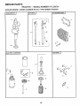
ASSEMBLY
Your new tractor has been assembled at the factory with exception of those parts left unassembled for shipping purposes,
To ensure safe and proper operation of your tractor all parts and hardware you assemble must be tightened securely. Use
the correct tools as necessary to insure proper tightness.
TOOLS REQUIRED
FOR ASSEMBLY
STEERING
A socket wrench set will make assembly easier. Standard
wrench sizes are listed,
(2) 7/16" wrenches
3/4" Socket w/drive ratchet
(t)
Tire pressure gauge
t/2" wrench
_
WHEEL
INSERT
_'_
HEX LOCKNUT
,, ;t\"+--'-"-'-
FLAT WASHER
Phillips Screwdriver
(t) 9/16" wrench
STEERING
WHEEL
Utility knife
When right or left hand is mentioned in this manual, it
means when you are in the operating position (seated
behind the steering wheel),
STEERING
TO REMOVE TRACTOR FROM CARTON
UNPACK
CARTON
,
Remove all accessible loose parts and parts cartons
from carton (See page 6),
°
Cut, from top to bottom, along lines on all four corners
of carton, and !ay panels fiat.
-
Check for any.additional
remove.
I
/
_7 i
t
t
/
loose parts or cartons and
1
/
f/
t
i
FIG. t
BEFORE ROLLING TRACTOR OFF SKID
ATI"ACH
•
STEERING
WHEEL
TO ROLLTRACTOR
section for location
(See Fig, 1)
Remove tocknut and large flat washer from steering
shaft.
°
Position front wheels of the tractor so they are pointing
straight forward.
o
•
Slide the steering sleeve over the steering shaft.
Position steering wheel so cross bars are horizontal
(left to right) and slide onto adapter.
°
Secure steering wheel to steering shaft with locknut
and large flat washer previously removed. Tighten
securely.
•
Snap steering wheel insert into center of steering
wheel.
°
Remove protective plastic from tractor hood and grill.
IMPORTANT: CHECK FOR AND REMOVE ANY STAPLES
IN SKiD THAT MAY PUNCTURE TIRES WHERE TRACTOR
IS TO ROLL OFF SKID.
7
OFF SKID (See Operation
and function
of controls)
=
Press lift lever plunger and raise attachment lift lever to
its highest position.
,
Release parking brake by depressing
pedal.
•
°
°
Place gearshift lever in neutral (N) position.
Roll tractor backwards off skid.
•
Remove banding holding discharge guard up against
tractor.
clutch!brake
ASSEMBLY
CONNECT
BATTERY
(See Fig. 2)
INSTALL
Adjust seat before tightening adjustment knob.
CAUTION: Do not short battery terminals. Before connecting battery, remove metal bracelets,
wristwatch
bands, rings, etc.
Positive terminal must be connected
first to prevent sparking from accidental grounding=
•
Remove cardboard packing on seat pan.
•
Place seat on seat pan and assemble shoulder bolt.
=
Assemble adjustment knob and flat washer loosely.
Do not tighten.
°
°
•
Lift hood to raised position.
Open terminal access doors, remove terminal protective caps and discard.
•
If this battery is put into service after month and year
indicated on label (label located between terminals)
charge battery for minimum of one hour at 6-10 amps.
•
First connect RED battery cable to positive (+) battery
terminal with hex bolt, fiat washer, lock washer and hex
nut as shown. Tighten securely.
°
Connect BLACK grounding cable to negative (-) battery terminal with remaining hex bolt, flat washer, lock
washer and hex nut. Tighten securely.
°
Close terminal access doors.
Use terminal access doors for:
•
•
•
°
°
inspection for secure connections
ware).
Inspection for corrosion.
Testing battery.
Jumping (if required).
Periodic charging.
HEX NUT_,
DISCARD
TERMINAL
PROTECTIVE
CAPS
SEAT (See Fig. 3)
Tighten shoulder bolt securely.
Lower seat into operating position and sit on seat.
°
Slide seat until a comfortable position is reached which
allows you to press clutch/brake pedal all the way
down.
,
Get off seat without moving its adjusted position.
-
Raise seat and tighten adjustment knob securely.
SEAT
BOLT R
\\
\, \\\
(to tighten hard-
LOCK
WASHER
/
ADJUSTMENT
KNOB
'
FLAT
WASHER
\..
HEX
\
BOLT
FIG. 3
CHECK
TIRE
PRESSURE
The tires on your tractor were overinfiated
shipping purposes, Correct tire pressure
best cutting performance,
Reduce tire pressure to PSI shown
SPECIFICATIONS" on page 3 of this
POSITIVE
(REO)
CABLE
CHECK
BRAKE
at the factory for
is important for
in "PRODUCT
manual.
SYSTEM
After you learn how to operate your tractor, check to see
that the brake is properly adjusted. See "TO ADJUST
BRAKE" in the Service and Adjustments section of this
manual.
NEGATIVE
(BLACK)
CABLE
FIG. 2
8
m
ii,ln
BLY
ASSI
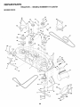
(See
•
Place the R.H. suspension arm on outward pointing
deck pin. tf necessary, rock and raise front of mower
to align deck pin with the hole in suspension arm.
Be sure tractor is on leve! surface and mower suspension
arms are raised with attachment lift contro!. Engage parking brake.
•
Cut and remove ties securing anti-sway bar and beits.
Swing anti-sway bar to left side of mower deck.
,
S!ide mower under tractor with discharge guard to right
side of tractor.
•
Connect anti-sway bar to chassis bracket under left
footrest and retain with double loop retainer spring.
•
Retain both suspension arms to deck pins with double
loop retainer springs.
Turn height adjustment knob clockwise to remove
slack from mower suspension.
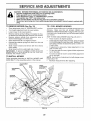
INSTALL MOWER
Figs. 4 and 7)
AND DRIVE
BELT
°
IMPORTANT: CHECK BELT FOR PROPER ROUTING IN
ALL MOWER PULLEY GROOVES. INSTALL BELT INTO
ELECTRIC CLUTCH PULLEY GROOVE.
•
•
Install one front link in top hole of the R.H. front mower
bracket and R.H. front suspension bracket. Retain
with two single loop retainer springs as shown.
Insta!l second front link in h H. front suspension bracket
only and retain _X,
ith single loop retainer spring as
shown.
°
Turn height adjustment knob counterclockwise
Stops.
•
Lower mower linkage with attachment lift control.
,
Place the L.H. suspension arm on outward pointing
deck pin. If necessary, rock and raise front of mower
to align deck pin with the hole in suspension arm.
Slide !eft side of mower back and install the unattached
front link in top hole of the L.H. front mower bracket.
Retain with single loop retainer spring as shown.
•
CHASSIS
BRACKET
Raise mower to highest position.
•
Assemble gauge wheeis (See "TO ADJUST GAUGE
WHEELS" in the Operation section of this manual).
CHECK
MOWER
LEVELNESS
For best cutting results, mower shou!d be properly leveled.
See "TO LEVEL MOWER HOUS!NG" in the Service and
Adjustments section of this manual.
CHECK
BELTS
until it
DOUBLE LOOP
RETAINER SPRING
(outward pointing
deck pins)
°
FOR
PROPER
POSITION
OF
ALL
See the figeres that are shown for replacing motion, mower
drive, and mower blade drive belts in the Service and
Adjustments section of this manual. Verify that the belts
are routed correctly.
FRONT
SUSPENSION
BRACKETS
ELECTRIC
CLUTCH
SUSPENSION
ARMS
FRONT
MOWER
BRACKET
FRONT
LINK
SHOULDER
BOLT
GAUGE
WHEEL
SINGLE
LOOP
RETAINER
SPRINGS
3/8-! 6
CENTER
LOCKNUT
3_ WASHER
ANTi-SWAY
BAR
DOUBLE LOOP
RETAINER
SPRING
IDLER /
PULLEY
DISCHARGE
FIG. 4
9
GUARD
ASSEMBLY
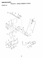
INSTALL MULCHER
=
PLATE (See Figs. 5 and 6)
DEFLECTOR
SHIELD
install two latch hooks to mulcher plate using screw,
washer, lock washer, and weld nut as shown.
NOTE: Pre-assemble weld nut to latch hook by inseiting
weld nut from the top With hook pointing down.
*
Tighten hardware securely.
,
Raise and hold deflector shield in upright position.
.
-
Place front of mulcher plate over front of mower deck
opening and slide into place, as shown.
Hook front latch into hole on front of mower deck.
-
Hook rear latch into hole on back of mower deck.
LATCH
HOOKS
FIG. 6
TO CONVERT
DISCHARGING
TO BAGGING
OR
v" CHECKLIST
Simply remove mulcher plate and store in a safe place.
Your mower is now ready for discharging or installation of
optional grass catcher accessory.
BEFORE YOU OPERATE AND ENJOY YOUR NEW
TRACTOR, WE WISH TO ASSURE THAT YOU RECEIVE
THE BES T PERFORMANCE AND SA TISFA CTION FROM
THIS QUALITY PRODUCT.
NOTE: It is not necessary to change blades. The mulcher
blades are designed for discharging and bagging also.
PLEASE REVfEW THE FOLLOWING
HOOK POINTS
DOWN
WELD NUT
FROM TIlE TOP
,/
All assembly instructions have been Completed.
,/
No remaining loose parts in carton.
v"
Battery is properly prepared and charged. (Minimum
1 hour at 6 amps).
Seat is adjusted comfortably and tighiened securely.
,/
LOCK
WASHER
WELD.
NUT
"N
LATCH
HOOK
HOOK
LOCK
WASHER
CHECKLIST."
,/
All tires are properly inflated. (For shipping purposes,
the tires were overinflated at the factory).
v"
Be sure mower deck is properly leveled side4o-sidel
front-to-rear for best cutting results. (Tires must be
properly inflated for leveling).
¢"
Check mower and drive belts. Be sure they are routed
properly around pulleys and inside all belt keepers.
v"
Check wiring. See that all connections are still secure
and wires are properly clamped.
WHILE LEARNtNG HOW TO USE YOUR TRACTOR, PAY
EXTRA A TTENTION TO THE FOLLOWING IMPORTANT
ITEMS:
WELD
NUT
WASHER
J
Engine oil is at proper level.
,/
Fuel tank is filled with fresh, clean, regutar unleaded
gasoline.
,I" Become familiar with all controls - their location and
function. Operate them before you start the engine.
MULCHER
PLATE
FIG. 5
v"
10
Be sure brake system is in safe operating condition.
OPERATION
These symbols may appear on your tractor or in literature supplied with the product. Learn and understand their meaning,
BATTERY
CAUTION OR
. WARNING
REVERSE
FORWARD
FAST
SLOW
ENGINE ON
ENGINE OFF
OIL PRESSURE
CLUTCH
LIGHTS ON
LIGHTS OFF
FUEL
CHOKE
MOWER HEIGHT
DIFFERENTIAL
LOCK
PARKING BRAKE
LOCKED
UNLOCKED
REVERSE
NEUTRAL
HIGH
L
o5
LOW
PARKING BRAKE
÷
MOWER LIFT
ATTACHMENT
CLUTCH ENGAGED
ATTACHMENT
CLUTCH DISENGAGED
IGNITION
HYDROSTATIC FREE WHEEL
(Hydro Models only)
DANGER, KEEP HANDS AND FEET AWAY
1!
OPERATION
KNOW YOUR TRACTOR
READ THIS OWNER'S
MANUAL
AND SAFETY
RULES
BEFORE
OPERATING
YOUR TRACTOR.
Compare the illustrations with your tractor to familiarize yourseff with the location of various controls and adjustments. Save
his manual for future reference.
ATTACHMENT
CLUTCH SWITCH
IGNITION
AMMETER
SWITCH
LiFT LEVER
THROTTLE
CONTROL
CHOKE
CONTROL
_
LIGHT SWITCH __!_'_
/
PLUNGER
_'F
ATTACHMENT
EVER
CLUTCH/BRAKE
PEDAL
PARKING BRAKE
_-tt
LEVER
HEIGHT
ADJUSTMENT
KNOB
GEARSHIFT
LEVER
FiG. 7
Our tractors conform to the safety standards of the American National Standards Institute.
ATTACHMENT CLUTCH SWITCH- Used to engage mower
blades or other attachments mounted to your tractor.
ATTACHMENT LIFT LEVER - Used to raise and lower
mower deck or other attachments mounted to your tractor,
CLUTCH/BRAKE
PEDAL - Used for declutching
braking the tractor and starting the engine.
HEIGHTADJUSTMENT
height.
IGNITION SWITCH - Used to start and stop the engine.
PARKING BRAKE LEVER- Locks clutch/brake pedat into
the brake position.
THROTTLE CONTROL - Used to control engine speed,
LIFT LEVER PLUNGER - Used to release attachment iift
lever when changing its position.
and
KNOB- Used to adjust the mowei _
CHOKE CONTROL - Used when starting a cold engine.
AMMETER
battery.
LIGHT SWITCH - Turns the headlights on and off.
GEARSHIFT LEVER - Selects the speed and direction of
the tractor.
12
- Indicates charging (+) or discharging (-) of
OPERATIC
The operation of any tractor can result in foreign objects thrown into the eyes, which can
result in severe eye damage. Always wear safety glasses or eye shields while operating
your tractor or performing any adjustments or repairs. We recommend a wide vision safety
mask over the spectacles or standard safety glasses.
HOW TO USE YOUR TRACTOR
TO SET PARKING
BRAKE
You r tractor is equipped with an operator presence
switch. When engine is running, any attempt
operator to leave the seat without first setting the
brake wilt shut off the" engine.
°
Depress clutch!brake pedal into full "BRAKE"
and hold.
-
sensing
by the
parking
TO USE THROTTLE
position
Place parking brake lever in "ENGAGED" position and
release pressure from clutch/brake pedal Peda! should
remain in "BRAKE" position. Make sure parking brake
will hold tractor secure.
THROTTLE
CONTROL
PUSH-IN TO
"DISENGAGE"
CHOKE
CONTROL
CAUTION:
Always stop tractor completely, as described above, before leaving the operator's
position; to empty
grass catcher, etc.
(See Fig. 8)
ATTACHMENT
CLUTCH SWITCH
PULL OUT TO
"ENGAGE"
TO USE CHOKE
HEIGHT
ADJUSTMENTKNOB
GEARSHIFT
LEVER
FIG. 8
STOPPING
CONTROL
(See Fig° 8)
Use choke control whenever you are starting a cold engine.
Do not use to start a warm engine.
= To engage choke control, pull knob out. Slowly push
knob in to disengage.
FORWARD
AND
BACKWARD
(See Fig. 8)
=ARK|NG
BRAKE
"ENGAGED"
POSITION
CLUTCWBRAKE
PEDAL"DR|VE"
POSITION
(See Fig. 8)
Always operate engine at full throttle.
•
Operating engine at less than full throttle reduces the
battery charging rate.
Full throttle offers the best bagging and mower performance.
TO MOVE
"BRAKE"
POSITION
CONTROL
(See Fig. 8)
MOWER BLADES °
Move attachment
position.
GROUND DRIVE-
clutch switch to "DISENGAGED"
•
Depress clutch/brake pedal into full "BRAKE" position.
= Move gearshift lever to neutral (N) position.
ENGINE ° Move throttle control to slow (,_1_) position.
NOTE: Failure to move throttle control to slow (,_)
position and allowing engine to idle before stopping may
cause engine to "backfire".
,
Turn ignition key to "OFF" position and remove key.
Always remove key when leaving tractor to prevent
unauthorized use.
Never use choke to stop engine.
NOTE: Under certain conditions when tractor is standing
idle with the engine running, hot engine exhaustgases may
cause "browning" of grass. To eliminate this possibility,
always stop engine when stopping tractor on grass areas.
The direction and speed of movement is controlled bY the
gearshift lever.
•
Start tractor with clutch/brake pedal depressed and
gearshift lever in neutral (N) position.
°
Move gearshift lever to desired position.
,
Slowly release clutch/brake pedal to start movement.
IMPORTANT: BRING TRACTOR TO A COMPLETE STOP
BEFORE SHIFTING OR CHANGING GEARS. FAILURE
TO DO SO WILL SHORTEN THE USEFUL LIFE OF YOUR
TRANSAXLE.
TO ADJUST
(See Fig. 8)
MOWER
CUTTING
HEIGHT
The cutting height is controlled by turning the height adjustment knob in desired direction.
o
Turn knob clockwise (f-_) to raise cutting height.
Turn knob counterclockwise (K",.)to lower cutting
height.
The cutting height range is approximately 1-1/2" to 4". The
heights are measured from the ground to the blade tip
with the engine not running. These heights are approximate and may vary depending upon soil conditions, height of grass and types of grass being mowed.
•
The average lawn should be cut to approximately 2-1/2
inches during the cool season and to over 3 inches
during hot months. For healthier and better Iooking
lawns, mow often and after moderate growth.
°
For best cutting performance, grass over 6 inches in
height should be mowed twice. Make the first cut
relatively high; the second to desired height.
TO ADJUST
GAUGE
WHEELS
(See Fig. 9)
Adjust gauge wheels with tractor on a flat level surface.
•
Adjust mower to desired cutting height (See 'q-O ADJUST MOWER CUTTING HEIGHT" in the Operation
13
section of this manual).
OPERATION
•
With mower in desired height of cut position, gauge
wheels should be assembled so they are slightly off the
ground, Install gauge wheel in appropriate hole with
shoulder bolt, 3/8 washer, and 3/8-16 Iocknut and
tighten securely.
Repeat for opposite side installing gauge wheel in
same adjustment hole.
slower position.
If stopping is absolutely necessary, push clutch/brake
pedal quickly to brake position and engage parking
brake.
Move gearshift lever to 1st gear. Be sure you have
allowed room for tractor to roll slightly as you restart
movement.
GAUGE
WHEEL
MOUNTING
BRACKET,__
_'_-_-r
o
"-'--
To restart movement, slowly release parking brake and
clutch/brake pedal.
Make all turns slowly
TO TRANSPORT
LOCKNUT
°
.... _,,\N3.. _-_"-GAUGE WHEEL
ii:t,_f_ii}
SHOULDER
-
When pushing or towing your tractor, be sure gearshift
lever is in neutral (N) position.
= Do not push or tow tractor at more than five (5) MPH.
NOTE: To protect hood from damage when transporting
your tractor on a truck or a trailer, be sure hood is closed
and secured to tractor. Use an appropriate means of tying
hood to tractor (rope, cord, etc.).
BOLT
FiG. 9
TO OPERATE
MOWER
(See Fig.
10)
Your tractor is equipped with an operator presence sensing
switch. Any attempt by the operator to leave the seat with
the engine running and the attachment clutch engaged wilt
shut off the engine.
.
Select desired height of cut.
•
Lower mower with attachment lift control.
.
Start mower blades by engaging attachment clutch
control.
= TO STOP MOWER BLADES - disengage attachment
clutch control.
BEFORE STARTING
CHECK
•
°
CAUTION: Do not operate the mower
without either the entire grass catcher,
on mowers so equipped, or the discharge guard in place.
=
ATTACHMENT
CLUTCH SWITCH
PULL OUT TO
Raise attachment lift to highest position with attachment lift control.
ATTACHMENT
LIFT LEVER HiGH
POSITION
ENGINE
THE ENGINE
OIL LEVEL (See Fig, 17)
The engine in your tractor has been shipped, from the
factory, already filled with summer weight oi!.
Check engine oil with tractor on level ground.
Remove oil fill cap/dipstick and wipe clean, reinsert the
dipstick and push it all the way down into the tube, wait
for a few seconds, remove and read oil level. If
necessary, add oil until "FULL" mark on dipstick is
reached. Do not overfill.
For cold weather operation you should change oil for
easier starting (See "OIL VISCOSITY CHART" in the
Customer Responsibilities section of this manual).
To change engine oil, see the Customer Responsibilities section in this manual.
ADD GASOLINE
°
,+"''--_
Fill fuel tank. Use fresh, clean, regular unleaded
gasoline with a minimum of 87 octane. (Use of leaded
gasoline will increase carbon and lead oxide deposits
and reduce valve life). Do not mix oil with gasoline.
Purchase fuel in quantities that can be used within 30
days to assure fuel freshness.
IMPORTANT: WHEN OPERATING 1N TEMPERATURES
BELOW 32°F(0°C), USE FRESH, CLEAN WINTER GRADE
GASOLtNE TO HELP INSURE GOOD COLD WEATHER
STARTING.
LOW
POSITION
iJ
'
TO OPERATE
•
WARNING:
Experience indicates that alcohol blended
fuels (called gasoho! or using ethanol or methanol} can
attract moisture which leads to separation and formation of
acids during stoi'age. Acidic gas can damage the fuel
system of an engine while in storage. To avoid engine
problems, the fuel system should be emptied before storage of 30 days or longer. Drain the gas tank, start the
engine and let it run until the fue! lines and carburetor are
empty. Use fresh fuel next season. See Sto_age lnstruc _
tions for additional information,
Never use engine or
carburetor cleaner products in the fuel tank or permanent
damage may occur.
FiG. 10
ON HILLS
Choose the slowest speed before starting up or down
hills.
Avoid stopping or changing speed on hills.
14
iJ
OPERATION
CAUTION: Fill to bottom of gas tank
filmer neck. Do not overfill. Wipe off any
spilled oil or fuet, Do not store, spill or
use gasoline near an open flame.
TO START
ENGINE
Depress clutch/brake
tf grass is extremely tall, it should be mowed twice to
reduce load and possible fire hazard from dried clippings. Make first cut relatively high; the second to the
desired height.
°
Do not mow grass when it is wet. Wet grass wit! plug
mower and leave undesirable clumps. Allow grass to
dry before mowing.
•
Always operate engine at full throttle when mowing to
assure better mowing performance and proper discharge of material. Regulate ground speed by selecting a low enough gear to give the mower cutting
performance as well as the quality of cut desired.
•
When operating attachments, select a ground speed
that wilt suit the terrain and give best performance of
the attachment being used.
(See Fig. 8)
When starting engine for the first time or if engine has run
out of fuel, it wilt take extra cranking time to move fue! from
the tank to the engine.
-
•
pedal and set parking brake.
•
Place gearshift lever in neutral (N) position.
•
Move attachment clutch to "DISENGAGED"
•
Pull choke control out to choke (N) position for cold
engine start. For warm engine start do not use choke
control.
MULCHING,
Move throttle control to midway between fast (,t_) and
slow (,_) positions.
IMPORTANT:
FOR BEST
PERFORMANCE,
KEEP
MOWER HOUSING
FREE OF BUll_T-UP
GRASS AND
TRASH.
CLEAN AFTER EACH USE.
e
•
position.
Insert key into ignition and turn key clockwise to"START"
position and release key as soon as engine starts. Do
not run starter continuously for more than fifteen
secondsper
minute. If engine does not start after
several attempts, move throttle control to fast (,_)
position, wait a few minutes and try again.
.
When engine starts, slowly push choke control in.
°
Move throttle control to fast (,_) position.
°
Allow engine to warm up for a few minutes before
engaging drive or attachments.
Tire chains cannot be used when the mower housing
is attached to tractor.
•
Mower should be properly leveled for best mowing
performance. See "TO LEVEL MOWER HOUSING" in
the Service and Adjustments section of this manual.
,
The left hand side of mower should be used for trimming.
°
Drive.so that clippings are discharged onto the area
that has been cut. Have the cut area to the right of the
machine. This will result in a more even distribution of
clippings and more uniform cutting.
•
•
Avoid cutting your lawn when it is wet. Wet grass tends
to form clumps and interferes with the mulching action.
The best time to mow your lawn is the early afternoon.
At this time the grass has dried and the newly cut area
will not be exposed to the direct sun.
•
For best results, adjust the mower cutting height so that
the mower cuts off only the top one-third of the grass
blades (See Fig, 12). For extremely heavy mulching,
reduce your width otcut on each pass and mow slowly.
TIPS
,
FIG. 12
°
When mowing large areas, start by turning to the right
so that clippings will discharge away from shrubs,
fences, driveways, etc. After one or two rounds, mow
in the opposite direction making left hand turns until
finished (See Fig. 11).
°
f
I
(
FiG, tl
TiPS
The special mulching blade will recut the grass clippings many times and reduce them in size so that as
they fall onto the lawn they will disperse into the grass
and not be noticed. Also, the mulched grass wilt
biodegrade quickly to provide nutrients for the lawn.
Always mulch with your highest engine (blade) speed
as this will provide the best recutting action of the
blades.
NOTE: If at a high altitude (above 3000 feet) or in cold
temperatures (below 32°F), the carburetor fuel mixture
may need to be adjusted for best engine performance. See
"TO ADJUST CARBURETOR" in the Service and Adjustments section of this manual.
MOWING
MOWING
15
Certain types of grass and grass conditions may require that an area be mulched a second time to completely hide the clippings. When doing a second cut,
mow across or perpendicular to the first cut path.
Change your cutting pattern from week to week. Mow
north to south one week then change to east to west the
next week. This wil! help prevent matting and graining
of the lawn.
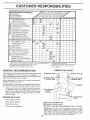
CUSTOMER
MAINTENANCE
RESPO
BILITiES
SCHEDULE
FILL tN DATES
AS YOU COMPLETE
REGULAR SERVICE
SERVICE DATES
Cheek Brake Operation
Check Tire Pressu/re
T
Check for Loose Fasteners
a
Sharpen/Replace
C
Lubrication Chart
A
Mower Biades
T
Check Battery Leve!iRecharge
D
Clean Battery and Terminals
R
CheckTransaxle
Cooling
Adjust Blade Bett(s)
Tension
Adjust Motion Drive Belt(s) Tension
Check Engine Oil Level
Change Engine Oil
Ciean Air Filter
E
N
CIean Air Screen
G
Inspect Muffler/Spark
J
Replace
N
Clean Engine Cooling
Replace
Attester
Oil FiIter (if equipped)
Fins
Spark Plug
Replace Air Filter Paper Cartridge
Replace
Fuel Filter
. Changemore oftenwhen operating under a heavy load or in high ambienttemperatures.
2 - Servfcemore often when operatingin dirty or dustyconditioner
3 - If equipped with oii filter, change oil every 50 hours.
4 -Reptace bladesmere oftenwhen mowing in sandy seii.
GENERAL
5 - if equipped
6 - Not required
7 - Tighten
with
adjustable
if equipped
front axle pivot
system,
with
maintenance-free
belt to 35 ft,-Ibs,
battery_
maximum.
Do r_ot overtighl[en,
RECOMMENDATIONS
The warranty on this tractor does not cover items that have
been subjected to operator abuse or negligence.
To
receive full value from the warranty, operator must maintain
tractor as instructed in this manual.
Some adjustments will need to be made periodically to
properly maintain your tractor.
All adjustments in the Service and Adjustments section of
this manual should be checked at least once each season.
®
Once a year you should replace the spark plug, clean
or replace air filter, and check blades and belts for
wear. A new spark plug and clean air filter assure
proper air-fuel mixture and help your engine run better
and last longer.
BEFORE
EACH
O ATTACHMENT"
CLUTCH
PIVOT(S)
USE
•
Check engine oil level.
,
Check brake operation.
,
,
Check tire pressure.
Check for loose fasteners.
GEARSHIFT(_
PIVOTS
(_SAE
30 OR 10W30 MOTOR OiL
®GENERAL
PURPOSE GREASE
® REFER TO CUSTOMER
RESPONSIBILITIES
,,=_,l_,_,,
_,,,> ......
SECTION
IMPORTANT:
DO NOT OIL OR GREASE
THE PIVOT POINTS
WHICH HAVE SPECIAL NYLON BEARINGS.
VISCOUS
LUBRICANTS WILL ATTRACT DUST AND DIRT THAT WiLL SHORTEN
THE LIFE OF THE SELF-LUBRICATING
BEARINGS..IF
YOU
FEEL THEY MUST BE LUBRICATED,
USE ONLY A DRY, POWDERED GRAPHITE
TYPE LUBRICANT
SPARINGLY.
16
RESPONSIB ILITIES
CUSTOMER
LI_,I,,,
iii
i,
ii i,in!,l,
ii ,i
, ,i,,_11
i iiil,,inlnl
....................
_
,i-i
ii
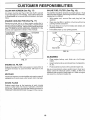
TRACTOR
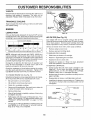
TO SHARPEN
Always observe Safety rules when performing any maintenance.
Care should be taken to keep the blade balanced. An
unbalanced blade will cause excessive vibration and eventual damage to mower and engine.
BRAKE
•
The blade can be sharpened with a file or on a grinding
wheel. Do not attempt to sharpen while on the mower.
,
To check blade balance, you will need a 5/8" diameter
steel bolt, pin, ora cone balancer. (When using a cone
balancer, follow the instructions supplied with balancer.)
Slide blade on to an unth readed portion of the steel bolt
or pin and hold the bolt or pin parallel with the ground.
if blade is balanced, it should remain in a horizontal
position. If either end of the blade moves downward,
sharpen the heavy end until the blade is balanced.
OPERATION
tf tractor requires more than six (6) feet stopping distance
at high speed in highest gear, then brake must be adjusted.
(See "TO ADJUST BRAKE" in the Service and Adjustments section of this manual).
=
TIRES
•
Maintain proper air pressure in all tires (See "PRODUCT SPECIFICATIONS" on page 3 of this manual).
•
Keep tires free of gasoline, oil, or insect control chemicals which can harm rubber.
o
Avoid stumps, stones, deep ruts, sharp objects and
other hazards that may cause tire damage.
BLADE
(See Fig. 14)
NOTE: Do not use a nail for balancing blade. The lobes of
the center hole may appear to be centered, but are not.
/
BLADE
CENTER HOLE
CARE
For best results mower blades must be kept sharp.
place bent or damaged blades.
BLADE
REMOVAL
Re-
(See Fig. 13)
Raise mower to highest position to allow access to
blades.
•
Remove hex bolt, lockwasher and flat washer securing
blade.
Install new or resharpened
towards deck as shown.
•
BLADE
518" BOLT
OR PIN
•
•
/
/
FIG, 14
blade with trailing edge up
BATTERY
Reassemble hex bolt, lock washer and flat washer in
exact order as shown..
Your tractor has a battery charging system which is sufficient for normal use. However, periodic charging of the
battery with an automotive charger will extend its life.
° Tighten bolt securely (30-35 Ft. Lbs. torque).
IMPORTANT: BLADE BOLT IS GRADE 8 HEATTREATED.
NOTE: We do not recommend sharpening blade- but if you
do, be sure the blade is balanced.
MANDREL
ASSEMBLY
BLADE
•
Keep battery and terminals clean.
•
Keep battery bolts tight.
•
Keep small vent holes.
°
Recharge at 6-10 amperes for 1 hour.
TO CLEAN BATTERY AND TERMINALS
Corrosion and dirt on the battery and terminals can cause
the battery to "leak" power.
TRAILING
EDGE
°
Remove terminal guard.
°
Disconnect BLACK battery cabie first then RED batten] cable and remove battery from tractor.
•
Wash battery with solution Of four tablespoons of
baking soda to one gaIlon of water. Be careful not to get
the soda solution into the cells.
FLA'[
LOCK
WASHER
HEX BOLT (GRADE B)*
•
Rinse the battery with plain water and dry.
*A GRADE 8 HEAT TREATED BOLT CAN BE
IDENTIFIED BY SIX LINES ON THE BOLT HEAD.
•
Clean terminals and battery cable ends with wire brush
until bright.
FIG. 13
°
Coat terminals with grease or petroleum jelly.
=
Reinstall battery (See "CONNECT BATTERY"
Assembly section of this manual).
17
in the
--
=
....
,.,
ESPO
CUSTOMER
.................
.......
......
,IU'm
V-BELTS
OIL FILL
CAP/D|PSTICK
Check V-belts for deterioration and wear after 100 hours of
operation and replace if necessary. The belts are not
adjustable, Replace belts if they begin to slip from wear.
TRANSAXLE
LITIES
COOLING
Keep transaxle free from build-up of dirt and chaff which
can restrict cooling.
OIL DRAIN
PLUG
ENGINE
LUBRICATION
FIG. i5
Only use high quality detergent oil rated with APf service
classification SF or SG. Select the oil's SAE viscositygrade
according to your expected operating temperature.
AIR FILTER (See Fig. 16)
Your engine will not run properly using a dirty air filter.
Clean the foam pre-cleaner after every 25 hours of operation or every season. Service paper cartridge every 100
hours of operation or every season., whichever occurs first
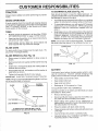
SAE VISCOSITY GRADES
Service air cleaner more often under dusty conditions.
.20 _
.30 _
30 °
.20 °
TEMPERATURE
.100
RANGE
80 °
0_
ANTICfPATED
10°
BEFORE
20 °
NEXT
30 _
•
40 °
Remove wing nut and cover.
•
Remove seal and cartridge p!ate.
TO SERVICE PRE-CLEANER.
O{L CHANGE
NOTE: Although multi-viscosity oils (5W30, t0W30 etc.)
improve starting in cold weather, these multi-viscosity oi!s
will result in increased oil consumption when used above
32°F. Check your engine oil !evet more frequently to avoid
possible engine damage from running low on oil.
Change the oi! after the first two hours of operation and
every 50 hours thereafter or at least once a year if the
tractor is not used for 50 hours in one year.
•
Slide foam pre-cleaner off cartridge.
•
Wash it in liquid detergent and water.
•
Squeeze it dry in a clean cloth.
•
SatUrate it in engine oil, Wrap it in clean, absorbent
cloth and squeeze to remove excess oil.
TO SERVICE CARTRIDGE
Check the crankcase oil level before starting the engine
and after each eight (8) hours of operation. Tighten o11fill
cap/dipstick securely each time yo u check the oil {evel.
•
Gently tap the flat side of the paper cartridge to dislodge dirt. Do not wash the paper cartridge or use
pressurized air, as this wilt damage the cartridge.
Replace a dirty, bent, or damaged cartridge.
TO CHANGE ENGINE OIL (See .Fig. 15)
°
Determine temperature range expected before oil change.
All oil must meet APt service classification SF or SG.
•
Reinstall the pre-cleaner (cleaned and oiled) over the
paper cartridge.
Reassemble air cleaner, cartridge plate, and seatl
• .
Be sure tractor is on levelsurface.
•
•
Oil will drain more freely when warm.
•
Catch oil in a suitable container.
•
Remove oil fill cap!dipstick. Be careful not to allow dirt
to enter the engine when changing oil.
•
Remove drain plug,
•
After oil has drained completely, replace oil drain plug
and tighten securely.
•
Refill engine with oil through oil fill dipstick tube. Pour
slowly. Do not overfill, For approximate capacity see
"PRODUCT SPECIFICATIONS"
on page 3 of this
manual.
•
Install the air cleaner cover and wing nut. Tighten wing
nut 1/2 turn to 1 full turn after nut contacts cover. Do not
overtighten.
o,o
PRE-CLEANER
Use gauge on oil fill cap/dipstick for checking leve!. Be
sure dipstick is in all the way for accurate reading.
Keep oil at "FULL" line on dipstick.
CARTRIDGE
FIG. 16
18
CUSTOMER
CLEAN
AiR SCREEN
RESPONSIBILITIES
(See Fig. 17)
IN-LINE
Air screen must be kept free of dirt and chaff to prevent
engine damage from overheating. Clean with a wire brush
or compressed air to remove dirt and stubborn dried gum
fibers.
ENGINE
COOLING
FINS (See Fig. 17)
Remove any dust, dirt or oif from engine cooling fins to
prevent engine damage from overheating. Engine blower
housing must be removed. Remove side panels and hood
(See "TO REMOVE HOOD AND GRILL ASSEMBLY" in the
Service and Adjustments section of this manual).
COOLING FINS
(BOTH SIDES)
FUEL FILTER
(See Fig. 18)
The fuel filter should be replaced once each season. If fuel
filter becomes clogged, obstructing fuel flow to carburetor,
replacement is required.
•
With engine cool, remove filter and plug fuel line
sections.
•
Place new fuel filter in position in fuel line with arrow
pointing towards carburetor.
,
Be sure there are no fuel line leaks and clamps are
properly positioned.
=
Immediately wipe up any spilled gasoline.
SCREEN
CLAMP
CLAMP
FUEL FILTER
\
FIG. 18
CLEANING
\
_
\
FIG. 17
ENGINE
Clean engine, battery, seat, finish-, etc. of all foreign
matter.
-
Keep finished surfaces and wheels free of all gasoline,
oil, etc.
°
Protect painted surfaces with automotive type wax.
OIL FILTER
Replace the engine oil filter every season or every other oil
change if the tractor is used more than 100 hours in one
year.
We do not recommend using a garden hose to clean your
tractor unless the electrical system, muffler, air filter and
carburetor are covered to keep water out. Water in engine
can result in a shortened engine life.
MUFFLER
inspect and replace corroded muffler and spark arrester (if
equipped) as it could create a fire hazard and/or damage.
SPARK
•
PLUGS
Replace spark plugs at the beginning of each mowing
season or after every 100 hours of operation, whichever
occurs first. Spark plug type and gap setting areshown in
"PRODUCT SPECIFICATIONS" on page 3 of this manual.
19
SERVICE
A
ADJUSTMENTS
*
Depress clutch/brake pedaK fully and set parking brake.
=
Place gearshift
in neutral (N)
position,
CAUTION:
BEFORE lever
PERFORMING
ANY
SERVICE OR ADJUSTMENTS:
*
Place attachment clutch in "DISENGAGED"
position.
°
Turn ignition key "OFF" and remove key.
o
Make sure the blades and all moving parts have completely stopped.
= Disconnect spark plug wire from spark ptug and place wire where it cannot come in contact with
plug,
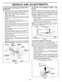
TO REMOVE
MOWER
TO LEVEL MOWER
(See Fig, 19)
°
,
•
Place attachment clutch in "DISENGAGED" position.
Turn height adjustment knob to lowest setting.
Lower mower to its lowest position.
Remove retainer spring holding anti_swaybar to chassis bracket and disengage anti-swaybar from bracket.
•
Remove retainer springs from suspension arms at
deck and disengage arms from deck.
•
Raise attachment lift to its highest position.
•
Remove two retainer springs from each front link and
remove links.
Slide mower forward and remove belt from electric
clutch pulley.
,
Slide mower out from under right side of tractor.
IMPORTANT: tFAN ATTACHMENT OTHERTHAH THE
MOWER DECK 1S TO BE MOUNTED ON THE TRACTOR,
REMOVE THE FRONT LINKS.
TO INSTALL
Adjust the mower while tractor is parked on level ground or
driveway.
Make sure tires are properly inflated (See
"PRODUCT SPECIFICATIONS" on page 3 of this manual).
If tires are over or underinflated, you will not properly adjust
your mower.
SIDE-TO-SIDE ADJUSTMENT (See Figs. 20 and 21 )
Raise mower to its highest position.
= At the midpoint of both sides of mower, measure height
from bottom edge of mowerto ground. Distance "A" on
both sides of mower should be the same or within t/4"
of each other.
°
°
=
MOWER
LIFT
LINKS
If adjustment is necessary, make adjustment on one
side of mower only.
To raise one side of mower, tighten lift link adjustment
nut on that side.
To lower one side of mower, loosen lift link adjustment
nut on that side.
NOTE: Each full turn of adjustment nut wi!lchange
height about !/8".
•
Recheck measurements after adjusting.
Follow procedure described in "INSTALL MOWER AND
DRIVE BELT" in the Assembly section of this manual.
ADJUSTMENT
NUTS
HOUSING
FRONT
SUSPENSION
SUSPE
ARMS
BRACKET
CHASSIS
BRAq
FRONT
SUSPENSION
BRACKET
LINKS
RETAINER
SPRINGS
RETAINER
SPRING
ANTI-SWAY
BAR
TMOWER
BRACKET
RETAINER
SPRINGS
FiG. t9
2O
mower
SERVICE
BOTTOM EDGE
OF MOWER TO
GROUND
AND ADJ
°
BOTTOM EDGE
OF MOWER TO
GROUND
•
•
°
STMENTS
To raise front ol mower, loosen nut "F" from trunnion on
both front links. Tighten nut "E" on both front links an
equal number of turns.
When distance "D" is 1/4" to 3/4" lower at front than
rear, tighten nut"F" against trunnion on both front links.
Recheck side-to-side adjustment.
Recheck side-to-side adjustment,
MANDREL
io
FIG. 20
_\_
SUSPENSION
ARM
FIG. 22
BOTH FRONT LINKS MUST BE EQUAL
LfFT LINK ADJUSTMENT
IN LENGTH
NUT
FiG. 21
i
FRONT-TO-BACK ADJUSTMENT (See Figs. 22 and 23)
IMPORTANT: DECK MUST BE LEVEL SIDE-TO-SIDE. IF
THE FOLLOWING' FRONT-TO-BACK ADJUSTMENT IS
NECESSARY, BE SURE TO ADJUST BOTH FRONT LINKS
EQUALLY SO MOWER WtLL STAY LEVEL SIDE-TOSIDE.
To obtain the best cutting results, the mower housing
should be adjusted so that the front is approximately 1/4" to
3/4" lower than the rear when the mower is in its highest
position.
Check adjustment on right side of tractor. Measure distance "D" directly in front and behind the mandrel at bottom
edge of mower housing as shown.
= Before making any necessary adjustments, check that
both front links are equal in length. Both links should
be approximately 10-3/8".
•
If links are not equal in length, adjust one link to same
length as other link.
To lower front of mower loosen nut "E" on both front
links an equal number of turns.
When distance "D" is 1/4" to 3/4" lower at front than
rear, tighten nuts "F" against trunnion on both front
links.
NUT "F"__
FRONT LINKS
.............
_
NUT "E"
TRUNNION
FIG. 23
21
SERVICE A
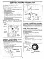
TO REPLACE
(See Fig. 24)
MOWER
BLADE
DRIVE
ADJUSTMENTS
TO ADJUST
BELT
CLUTCH
(See
Fig. 25)
The electric dutch should provide years of service. The
clutch has a built-in brake that stops the pulley within 5
seconds. Eventually, the internal brake will wear which
may cause the mower blades to not engage, or, to not stop
as required. Adjustments should be made by your nearest
authorized service centeddepartmenL
.
Make sure attachment clutch and ignition switches are
in "OFF" position.
= Adjust the three nylon Iocknuts until space between
clutch plate and rotor measures .012" at all three slot
locations cut in the side of brake plate.
NOTE: After installing a new electric clutch, run tractor at
full throttle and engage and disengage electric clutch 10
cycles to wear in clutch plate.
Park the tractor on level surface. Engage parking brake.
Remove mower drive belt (See'%O REPLACE MOWER
DRIVE BELT" in this section of this manual).
°
Remove mower (See "TO REMOVE MOWER" in this
section of this manual).
Remove four screws from R.H. mandrel cover and
remove cover. Unhook spring from bolt on mower
housing.
• Carefully roll belt off R.H. mandrel pulley.
•
Remove belt from center mandrel pulley, idler pulley,
and L.H. mandrel pulley.
•
Remove any dirt or grass which may have accumulated around mandrels and entire upper deck surface.
•
Check secondary idler arm and idler to see that they
rotate freely.
,, Be sure spring is hooked in secondary idler arm and
sway-bar bracket.
•
lnstafl new belt in lower groove Of L.H. mandrel pulley,
idler pulley, and center mandrel pulley as shown.
•
Roll belt over R,H. mandrel pulley. Make sure belt is in
all grooves properly.
Reconnect spring to bolt in mower housing and reinstall R.H. mandrel cover.
•
Reinstall mower to tractor (See "INSTALL MOWER
AND DRIVE BELT" in the Assembly section of this
manual).
.
Reassemble mower drive belt (See "TO REPLACE
MOWER DRIVE BELT" in this section of this manual).
L.H.
MANDREL
ATTACHMENT
MOWER
BLADE
DRIVE BELT
FIG. 25
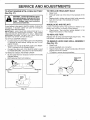
TO ADJUST
(See Fig. 26)
Your tractor is equipped with an adjustable brake system
which is mounted on the right side of the transaxle.
if tractor requires more than six (6).feet stopping distance
.at high speed in highest gear, then brake must be adjusted.
,
Depress clutchlbrake pedal and engage parking brake.
Measure distance between brake operating arm and
nut "A" on brake rod.
_
•
If distance is other than 1-1/2", loosen jam nut and turn
nLft "A" until distance becomes 1-t/2". Retighten jam
nut against nut "A".
Road test tractor for proper stopping distance as stated
above. Readjust if necessary. If stopping distance is
stitt greater than six (6) feet in highest gear, further
maintenance is necessary, Contact your nearest authorized service center/department.
CENTER
MANDREL
IDLER
PULLEY
R,R.
MANDREL
COVER
SECONDARY
IDLER ARM
SWAY-BAR
BRACKET
BRAKE
WITH PARKING
BRAKE "ENGAGED"
SCREW
FIG. 24
__
NUT "A"
FIG, 26
22
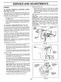
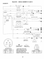
SERVICE
TO REPLACE
(See Fig. 27)
MOTION
DRIVE
AND ADJUSTMENTS
BELT
Park the tractor on level surface. Engage parking brake.
For assistance, there is a belt installation guide decal on
bottom side of left footrest.
•
Remove mower (See "TO REMOVE MOWER" in this
section of this manual.)
=
Disconnect clutch wire harness.
•
•
o
•
Remove clutch ]ocat0r.
Remove upper belt keeper.
Remove belt from stationary idler and clutching idler.
Pu]l belt slack toward rear of tractor. Remove belt
upwards from transaxle pulley by deflecting belt keep_
ers.
•
Pu]] belt toward front of tractor and re move downwards
from around electric clutch.
•
Install new belt by reversing above procedure.
IMPORTANT:
MAKE SURE UPPER BELT KEEPER IS
POSITIONED PROPERLY BETWEEN LOCATOR TABS
AND ELECTRIC CLUTCH WIRE CONNECTION
IS
_ECURE.
kk _
i_ENTER
TiE ROD _
ROD
LO_
FIG. 29
TO ADJUST
STEERING
WHEEL
ALIGNMENT
CLUTCH LOCATOR
CLUTCH
if steering wheel crossbars are not horizontal (left to right)
when wheels are positioned straight forward, remove steering wheel and reassemble per instructions in the Assembly
section of this manual.
LOCATORTABS
UPPER BELT
KEEPER
IDLER
FRONT WHEEL
TOE-IN/CAMBER
The front wheel toe4n and camber are not adjustable on
your tractor. If damage has occurred to affectthe front
wheel toe-in or camber, contact your nearest authorized
service center/department.
IDLER
TRANSAXLE
TO REMOVE WHEEL
(See Fig. 30)
CLUTCH
WIRE
HARNESS
°
°
FIG. 27
TRANSAXLE
SHIFTER
LINKAGE
JUSTMENT (See Figs. 28 and 29)
AND
•
°
AD-
°
The transaxle should be in neutral when the gear shift lever
is in the neutral (N) (lock gate) position. The adjustment is
preset at the factory; however, if adjustment is needed,
proceed as follows:
°
Make sure transaxfe is in neutral (N).
•
Loosen two locknuts on tie rod,
° Turn center rod until gearshift lever fails into neutral
lock gate on fender console.
,
Tighten locknuts securely.
°
FOR REPAIRS
Block up axle securely_
Remove axle cover, retaining ring and washers to aIIow
wheef removal (rear wheel contains a square key - Do
not lose).
Repair tire and reassemble.
On rear wheels only: align grooves ir_ rear wheel hub
and axle. Insert square key.
Reptace washers and snap retaining ring securely in
axle groove.
Replace axle cover.
WASHERS
RETAINING,
RING
AXLE
SQUARE KEY
(REAR WHEEL ONLY)
FIG. 30
F_G, 28
23
ERVICE A
D ADJUSTMENTS
TO REPLACE
TO START ENGINE WITH A WEAK BATTERY
(See Fig. 31)
•
°
=
-
HEADLIGHT
BULB
Raise hood.
Putt bulb holder out of the hole in the backside of the
grill,
Repiace bulb in holder and push bulb holder securely
back into the hole in the backside of the gritl,
Close hood.
INTERLOCKS
AND RELAYS
tf your battery is too weak to start the engine, it should be
recharged. If "jumper cables" are used for emergency
starting, follow this procedure:
IMPORTANT: YOUR TRACTOR IS EQUIPPED WITH A 12
VOLT NEGATIVE GROUNDED SYSTEM. THE OTHER
VEHICLE MUST ALSO BE A t2 VOLT NEGATIVE
GROUNDED SYSTEM. DO NOT USE YOUR TRACTOR
BATTERY TO START OTHER VEHICLES.
TO ATTACH JUMPER CABLES -
Loose or damaged wiring may cause your tractor to run
poorly, stop running, or prevent it from starting.
Check wiring. See electrical wiring diagram in the
Repair Parts section of this manual.
•
TO REMOVE HOOD
(See Fig, 32)
TO REPLACE
FUSE
Replace with 30 amp automotive4ype plug-in fuse.
fuse holder is located behind the dash.
Connect each end of the RED cable to the POSITIVE
(+) terminal of each battery, taking care not to short
against chassis.
°
Connect one end of the BLACK cable to the NEGATIVE (-) terminal of fully charged battery.
Connect the other end of the BLACK cable to good
CHASSIS GROUND, away from fuel tank and battery.
TO REMOVE CABLES, REVERSE OROER •
BLACK cable first from chassis and then from the fully
charged battery.
•
RED cable last from both batteries.
AND GRILL
Raise hood.
•
•
Unsnap headlight wire connector.
Stand in front of tractor. G rasp hood at sides, tilt toward
engine and lift off of tractor.
To replace, reverse above procedure.
•
....
\
HEADLIGHT
",'
HOOD
"NEGATIVE"
(+)
(-)
[
ASSEMBLY
,
i
"POSITIVE
J
FIG. 32
FIG, 31
24
The
_
CONNECTOR
CE AND ADJUSTMENTS
ENGINE
ACCELERATION
TO ADJUST
THROTTLE
(See Figs. 33 & 34)
CONTROL
=
CABLE
The throttle control has been preset at the factory and
adjustment should not be necessary. Check adjustment as
described below before loosening cable. If adjustment is
necessary, proceed as follows:
o
With engine not running, move throttle control lever to
fast (,_) position.
•
Check that speed control lever is against stop screw, tf
it is not, loosen casing clamp screw and pul! throttle
cable until !ever is against screw. Tighten clamp screw
securely.
TO ADJUST
CARBURETOR
(See
TEST-
Move throttle control lever from stow
position. If engine hesitates oi_dies,
screw out (counterclockwise)
!/8 turn.
continue to adjust, if necessary,_untit
ates smoothly.
High speed
may result.
stop is factory
adjusted.
(,_)
to fast (,1_)
turn idle mixture
Repeat test and
engine acceler-
Do not adiust-damage
IMPORTANT:
NEVER TAMPER
WtTH THE ENGINE
GOVERNOR,
WHICH IS FACTORY
SET FOR PROPER
ENGINE SPEED. OVERSPEEDtNG
THE ENGtNE ABOVE
THE
FACTORY
HIGH
SPEED
SETTING
CAN
BE
DANGEROUS.
IF YOU THINKTHE
ENGINE-GOVERNED
HIGH SPEED NEEDS ADJUSTING,
CONTACT
YOUR
NEAREST
AUTHORIZED
SERVICE
CENTER/
DEPARTMENT,
WHICH HAS PROPER EQUIPMENT
AND
EXPERIENCE
TO
MAKE
ANY
NECESSARY
ADJUSTMENTS.
Fig. 35)
The carburetor has been present at the factory and adjustment should not be necessary. However, minor adjustment
may be required to compensate for differences in fuel,
temperature, altitude or load. If the carburetor does need
adjustment, proceed as follows:
CASING
CLAMP
SCREW
In general,_turning the adjusting needles in (clockwise)
decreases the supply of fuel to the engine giving a leaner
fuel/air mixture. Turning the adjusting needles out (counterclockwise) increases the supply of fuel to the engine
giving a richer fueltair mixture.
IMPORTANT:
DAMAGE TO THE NEEDLES AND THE
SEATS IN CARBURETOR MAY RESULT IF SCREW iS
TURNED IN TOO TIGHT.
STOP SCREW
SPEED CONTROL
LEVER
THROTTLE
CABLE
PRELIMINARY SETTING °
Be sure you have a clean air filter, and the throttle
control cable is adjusted properly (see above).
•
With engine off turn idle fuel adjusting needle in (cbckwise) closing it finger tight and then turn out (counterclockwise) 1-t/4 turns.
-
Turn main fuel adjusting needle in (clockwise) closing
finger tight and then turn out (counterclockwise) 1 turn.
FIG. 33
STOP
SPEED
CONTROL
LEVER
FINAL SETTING °
Start engine and a!low to warm for five minutes. Make
final adjustments with engine running and shift/motion
control lever in neutral (N) position.
=
With thrott!e control lever in fast (,e_)position, turn main
fuel adjusting needle in (clockwise) until engine begins
to die then turn out (counterclockwise) until engine
runs rough. Turn needle to a point midway between
those two positions.
,
FIG. 34
ldfe s__
- Withthrottle control lever in slow
(,_)
position, engine should idle at 1400 RPM. tf
engine idles too slow or fast, turn idle speed adjusting
screw in or out until correct idle is attained.
•
Lc_lefuel needle set_
- With throttle control lever in
slow (._) position, turn idle fuel adjusting needle in
(clockwise) until engine begins to die and then turn out
(counterclockwise) until engine runs rough. Turn needle
to a point midway between those two positions.
°
Recheck idle speed. Readjust if necessary.
IDLE SPEED
ADJUSTING
SCREW
___
Xf.._.
0_/j7
25
FIG, 35
NEEDLE
.
STORAGE
ENGINE
Immediately prepare your tractor for storage at the end of
the season or if the tractor will not be used for 30 days or
q_ore.
FUEL SYSTEM
IMPORTANT:
IT IS IMPORTANT
TO PREVENT
GUM
DEPOSITS
FROM FORMING
IN ESSENTIAL
FUEL
SYSTEM PARTS SUCH AS CARBURETOR,
FUEL FILTER,
FUEL HOSE, OR TANK DURING
STORAGE,
ALSO,
EXPERIENCE
INDICATES
THAT ALCOHOL
BLENDED
FUELS (CALLED GASOHOL
OR USING ETHANOL
OR
METHANOL) CAN ATTRACT
MOISTURE WHICH LEADS
TO SEPARATION
AND FORMATION
OF ACIDS DURING
STORAGE.
ACIDIC
GAS CAN DAMAGE
THE FUEL
SYSTEM OF AN ENGINE WHILE IN STORAGE.
CAUTION: Never store the tractor with
gasoline in the tank inside a building
where fumes may reach an open flame
or spark.
Allow the engine to cool
before storing in any enclosure.
TRACTOR
Remove mower from tractor for winter storage. When
mower is to be stored for a period of time, clean it thor+
oughly, remove all dirt, grease, leaves, etc° Store in a
clean, dry area.
•
Clean entire tractor (See "CLEANING" in the Customer
Responsibifities section of this manual).
+
Inspect and replace belts, if necessary (See belt replacement instructions in the Service and Adjustments
section of this manual).
°
Lubricate as shown in the Customer Responsibilities
section of this manual.
°
Be sure that al! nuts, bolts and screws are securely
fastened. Inspect moving parts for damage, breakage
and wear. Replace if necessary.
Touch up all rusted or chipped paint surfaces; _sand
lightly before painting.
°
.
Fully charge the battery for storage.
,
After a period of time in storage, battery may require
recharging.
°
=
Drain the fuel tank.
°
Start the engine and let it run until the fuel lines and
carburetor are empty.
°
Never use engine or carburetor cleaner products in the
fuel tank or permanent damage may occur.
Use fresh fuel next season.
NOTE: Fuel stabilizer is an acceptable alternative in
minimizing the formation of fuel gum deposits during storage. Add stabilizer to gasoline in fuel tank or storage
container. Always follow the mix ratio found on stabilizer
container. Run engine at least 10 minutes after adding
Stabilizer to allow the stabilizer to reach the carburetor. Do
not drain the gas tank and carburetor if using fuel stabilizer.
ENGINE
OIL
Drain oil (with engine warm) and replace with clean engine
oi!. (See "ENGINE" in the Customer Responsibilities
section of this manual).
CYLINDERS
To help prevent corrosion and power leakage during
long periods of storage, battery cables should be
disconnected and battery cleaned thoroughfy (see "TO
CLEAN BATTERY AND TERMINALS" in the Customer Responsibilities section of this manual).
•
Remove spark plug(s).
°
Pour one ounce of oil through spark plug hole(s) into
cylinder(s).
Turn ignition keyto "START" position fora few seconds
to distribute oil+
+
Replace with new spark plug(s).
After cleaning, leave cables disconnected and place
cables where they cannot come in contact with battery
terminals_
OTHER
•
Be sure battery drain tube is securely attached.
•
Do not store gasoline from one season to another.
°
If battery is removed from tractor for storage, do not
store battery directly on concrete or damp surfaces.
°
Replace your gasoline can if your can starts to rust.
Rust and/or dirt in your gasoline will cause problems.
°
If possible, store your tractor indoors and cover it to
give protection from dust and dirt.
+
Cover.your tractor with a suitable protective cover that
does not retain moisture. Do not use plastic. Plastic
cannot breathe which allows condensation to form and
will cause your tractor to rust.
IMPORTANT: NEVER COVERTRACTOR WHILE ENGINE
AND EXHAUST AREAS ARE STILL WARM.
26
TRO
LESHOOT!
PROBLEM
CAUSE
Will not start
t.
Out of fuel.
2.
3.
4.
5.
6.
7.
Engine not "CHOKED"
Engine flooded.
Bad spark plug.
Dirty air filter.
Dirty fuel filter.
Waterin fueI.
8.
9.
10.
Engine
Engine
start
will not turn over
clicks but will not
Loss of power
CORRECTION
1.
Fil! fuel tank.
properly.
2.
3.
4.
5.
6,
7.
See "TO START ENGINE" in Operation section,
Wait several minutes before attempting to start.
Replace spark pfug.
Clean/replace air filter.
Replace fuel filter.
Drain fue_ tank and carburetor, refill tank with fresh
Loose or damaged wiring,
Carburetor out of adjustment.
Engine valves out of adjustment.
8.
9.
10.
gasoline and replace fuel filter.
Check all wiring,
Contact an authorized service center/department
Contact an authorized service center/department
1,
2.
3.
4.
5.
6.
7.
8.
Clean/replace air filter.
Replace spark plug.
Recharge or replace battery.
Replace fuet filter.
Drain fuel tank and refill with fresh gasoline.
Check all wiring.
Contact an authorized service center/department.
Contact an authorized service center/department
1.
2.
3..
4.
5.
6.
7.
8.
9.
Depress clutch/brake pedal,
Disengage attachment clutch.
Recharge or replace battery,
Replace fuse.
CIean battery terminals.
Check all wiring.
Check/replace ignition switch.
Check/replace solenoid or starter.
Contact an authorized service center/department
1.
2.
3.
4.
5.
6.
7.
Dirty air filter.
Bad spark plug.
Weak or dead battery.
Dirty fuet filter.
Stale or dirty fuel
Loose or damaged wiring.
Carburetor out of adjustment.
8.
Engine vatves out of adjustment.
t.
2.
3.
4.
Clutch/brake pedal not depressed.
Attachment clutch is engaged.
Weak or dead battery.
Blown fuse.
5.
6.
7.
8.
9.
Corroded battery terminals.
Loose or damaged wiring.
Faulty ignition switch.
Faulty solenoid or starter.
Faulty operator presence switch(es},
I.
2.
3.
4.
Weakor dead battery.
Corroded battery terminals,
Loose or damaged wiring.
Faulty solenoid or starter.
t,
2.
3.
4,
Recharge or replace battery.
Clean battery terminals.
Check all wiring.
Check/replace solenoid or starter.
1.
2.
3.
4,
5.
6,
7.
8,
9.
Cutting too much grass/too fast.
Throttle in "CHOKE _ position.
Build-up of grass, leaves and trash under mower.
Dirty air filter.
Low oil level/dirty oil.
Faulty spark pIug.
Dirty fue! filter.
Stale or dirty fue!,
Water in fuel,
t.
2.
3.
4.
5.
6,
7,
8.
9.
Set in "Higher Cut" position/reduce speed.
Adjust throttle control.
Clean underside of mower housing.
Clean/replace air filter.
CheckoiI level/change oil,
Clean and regap or change spark plug.
Replace fuel filter.
Drain fuet tank and refill with fresh gasoline.
Drain fuel tank and carburetor, refill tank with fresh
gasoline and reptace fuel filter.
Connect and tighten spark plug wire.
Clean engine air screen/fins.
Clean/replace muffler.
Check alt wiring.
Contact an authorized service center/department.
Contact an authorized service center/department
10.
1t.
I2.
13,
14.
15.
Excessive vibration
G POINTS
1.
2.
3.
10.
!I.
12.
13.
14.
15.
Spark plug wire toose.
Dirty engine air screen/fins.
Dirty/clogged muffler.
Loose or damaged wiring.
Carburetor out of adjustment.
Engine valves out of adjustment.
Worn, bent or loose blade,
Bent bIade mandrel.
Looseldamaged part(s).
1.
2.
3,
27
Replace blade. Tighten blade bolt.
Replace blade mandrel.
Tighten loose part(s). Replace damaged
parts.
TROUBLESHOOTi
PROBLEM
G POINTS
CAUSE
Engine continues to run
when operator leaves seat
with attachment clutch
CORRECTION
Faulty operator-safety
presence control system.
1.
Check wiring, switches and connections.
If not
corrected, contact an authorized service center/
department.
engaged
Poor cut - uneven
1.
2.
Worn, bent or loose blade.
Mower deck not level.
1,
2.
Replace btade. Tighten blade bolt,
Level mowerdeck,
3.
4.
Buitdup of grass, leaves, and trash under mower.
Bent blade mandrel.
5.
Clogged mower deck vent holes from buildup of
grass, leaves, and trash around mandrels.
3.
4.
5.
Ctean underside of mower housing.
Replace blade mandrel,
Clean around mandrels to open vent holes.
Mower blades will not
rotate
1,
Obstruction
1.
Remove obstruction.
2_
3.
4.
Worn/damaged mower drive belt.
Frozen idler puItey.
Frozen blade mandrel,
2.
3.
4,
Replace mower drive belt.
Replace idler pulley,
Replace blade mandrel.
Poor grass discharge
t,
2.
3.
4.
Engine speedtoo slow.
Travet speed too fast.
Wet grass.
Mower deck not teve},
l.
2.
3.
4.
Place throttle control in "FAST" position,
Shift to stower speed.
Allow grass to dry before mowing.
Level mower deck.
5.
6,
7.
8,
Low/uneven tire air pressure.
Worn, bent or loose blade.
Buildup of grass, leaves and trash under mower.
Mower drive bett worn.
9,
t0.
11.
BladesimproperIyinstatled.
improper blades used,
C!ogged mower deck vent holes from buildup of
grass, leaves, and trash around mandrels.
in clutch mechanism.
_l,
==
Headlight(s) not working
(if so equipped)
Battery
5.
6,
7.
8.
9,
10.
t 1.
will not charge
Engine "backfires"
when turning engine
"OFF"
Checktires for proper air pressure.
Replace/sharpen b!ade. Tighten blade bolt.
Clean underside of mower housing,
Replace mower drive belt,
Reinstall blades sharp edge down,
Replace witl_ blades listed in this manuat.
Clean around mandrels to open vent holes.
i,,J,
:vl i
x
1,
Switch is "OFF".
1.
Turn switch "ON".
2,
3.
4.
5.
Bulb(s) burned out,
Faulty light switch.
Loose or damaged wiring,
Blown fuse.
2.
3.
4,
5.
Replace bulb(s).
Check/replace light switch.
Check wiring and connections.
Replace fuse.
1.
2.
Bad batteryceI!(s).
Poor _abte connections.
!,
2,
Replace battery.
Check/clean all connections.
3.
4.
Fauity regulator (if so equipped).
Faulty alternator,
3.
4,
Replace regulator.
Replace alternator.
1.
Engine throttle control not set at "SLOW"
position for 30 seconds before stopping engine.
t.
Move throttte controt to "SLOW" position and atbw
to idle for 30 seconds before stopping engine.
28
TRACTOR
- - MODEL NUMBER
917.256701
SCHEMATIC
Q
GFC
NON-REMOVABLE
CONNECTIONS
IGNITION
SWITCH
1 1.....i
OFF
M+G
START
ON '
B+
BS
+L+ L
REMOVABLE
CONNECTIONS
WIRING INSULATED
CLIPS
NOTE: tF WIRING INSULATED
CLIPS WERE REMOVED FOR
SERVICING OF UNIT, THEY
SHOULD BE REPLACED TO
PROPERLY SECURE YOUR WIRING
29
D
_A
PTO SWITCH
POSITION
OFF
CIRCUIT
,
A+D _'
REPAIR PARTS
TRACTOR
- - MODEL NUMBER
917.256701
ELECTRICAL
40
42
16
24
26
/
34
19
45
11
25
5t
\
3
29
7
28
3O
REPAIRPARTS
TRACTOR
- - MODEL NUMBER
917.256701
ELECTRICAL
KEY
NO.
1
2
3
4
6
7
8
9
t0
11
12'
16
!9
20
21
22
24
25
26
28
29
30
31
32
33
34
40
4!
42
43
44
45
49
50
51
52
55
70
PART
NO.
DESCRIPTION
146140
74760412
STD551025
STD55!125
STD541025
7697J
7603J
109596X
145211
145209
145769
153664
STD551125
73350400
136850
4152J
4799J
146148
108824X
145491
121305X
144921
140400
141226
140403
1t0712X
149170
71110408
131563
145673
73640400
I22822X
153249
146283
140405
141940
17490508
140427
NOTE:
Battery
Bolt, Hex 1/4-20 UNC x 3/4
Washer
Washer
Nut
Tube, Plastic
Tray, Battery
Clamp, Hose
Bolt, Btr. Frt 1/4-20 x 7.5
Hotddown Btr. Dash
Nut, Push Nylon 1/4" Battery
Switch _ntedock Pushqn
Washer, Lock
Nut, Hex, Jam t/4-20 UNC
Harness, Light Socket W/4152J
Bulb, Light
Cable Battery
Cable, Battery
Fuse
Cable, Ground
Switch, Plunger
Switch, Ignition
Nut, Ignition
Cover, Ignition Switch
Key, Ignition
Switch, Light
Harness, Ignition
Bolt Blk Fin. Hex 1/4-20 UNC x 1/2
Cover, Terminal
Solenoid
Nut, Keps Btk. Hex 1/4-20 UNC
Ammeter Rectangular 15 Amp
Washer Pinned Delta
Switch PTO 3 Pot Red Delta
Ring Retainer PTO
Wire Loop
Screw Thdrol 5/16-18 x 1/2 TYT
Harness Engine Koh 18 TWN 15 AR
All component dimensions
t inch = 25:4 mm
31
given in U.S. inches
REPAIR PARTS
TRACTOR
CHASSIS
-- MODEL NUMBER
917.256701
ANDENCLOSURES
3O
119
36
_
24
87
29
17
36
f
26
25
47
28
26
121
122
31
44
9O
125
71
66
115
3
86
140
1
11
114
26
33
t0
26
32
117
REPAIR PARTS
TRACTOR
CHASSIS
-- MODEL
NUMBER
917.256701
AND ENCLOSURES
KEY
NO.
PART
NO.
1 151169
2 140356
3 17490612
6 145206
7 145351
8 126471X
9 145203
10 72140608
11 145218
13 145217
17 136673X558
24 STD523710
25
19131312
26 STD541437
28 136373X428
29 136374
30 140002X558
31 137113
33 145244X558
34 145243X558
35 STD533707
36 108067X
38 139886
39 139887
44 140675
47 t05531X
50 137304
59 1t0436X
60 72140606
64 150272
66 143485X014
71 73640400
73 17580408
74 STD541437
86 136670X558
87 t36671X558
90 STD551025
100 105037X
114 145349
115 121794X
117 144283
119 19092016
120 137271
121 137269
122 137270
!23 136814
124 136813
125 74180412
140 150556
-8022J
NOTE:
DESCRIPTION
Chassis
Drawbar
Screw, Thdrol. 3/8-16 x 3/4 Type TT
Saddle
Shield Heat Kohler MV18
Clip, Fuel Line
Dash, Plastic
Bolt, Carriage 3/8q 6 x 1
Panel, Dash, LH
Panel, Dash, RH
Hood Assembly
Bolt
Washer !3/32 x 13/16 x 12 Gauge
Nut
Gdlt
Lensl Bar, Clea_r
Fender
Bracket Assembly, Fender
Footrest, LH
Footrest, RH
Bott
NUt, Pat
Bracket Assembly, Pivot, LH
Bracket AsSembly, Pivot, RH
Fender Strap
Nut, Push, Nylon
Rod, Support Hood
Bushing, Snap, Split
Bolt Rdhd Sq NK 318-16 x 3/4
Dash, Lower
Plate, Dash
Nut
Screw Tap Tite 1/4-20 x 1/2
Nut Crown!ock 3!8-16 UNC
Panel Assembly, RH
Panel Assembly, LH
Washer t7/64
Strip Foam t8"
Bracket, Support, Dash
Cover, Access
Washer Serrated Disk 13/32 x 1
Washer 9/32 x 1-!/4 x 16 Ga.
Rivet, Ratchet, Female
Washer, Nylon
Rivet, Rachet, Male
Bracket Assembly, Front Pivot Hinge, LH
Bracket Assembly, Front Pivot Hinge, RH
Screw, Machine 1/4-20 x 3/4
Bracket Chassis Front
Plug Dash Blk 500 Dia E. Lift
All component dimensions given in U.S. inches
! inch = 25.4 mm
33
REPAIR PARTS
TRACTOR--
MODEL NUMBER
917.256701
DRIVE
33
43
23
51
5
38
110
62
35
45
36
37
46
i
26
27
34
REPAIR PARTS
TRACTOR
- - MODEL NUMBER 917.256701
DRIVE
KEY
NO.
PART
NO.
1
145607
2
3
4
5
6
146682
123666X
12000028
121520X
17490512
8 141002
9 137140
10 STD561210
I1 105701X
12 19151216
13 74550412
14 STD551125
15 74490544
17 126197X
18 STD523710
19 STD541437
20 150280
21 106933X
22 130804
23 137141
24 STD541237
25 I06888X
26 STD551037
27 STD561210
28 145204
29 124236X
30 130807
3t 127275X
32 74760512
33 72140506
34 151128
35 t20183X
36 STD551062
37 STD571810
38 123674X
39 STD523727
40 4470J
41 153399
42 19131312
DESCRIPTION
Transaxle, Dana, Model Number
4360-97
Spring, Brake Return
Pulley, Transaxte
Ring, Retainer
Strap, Torque
Screw, Hex, Washer, Thread
Rolling 5/16-18 x 3/4
Rod, Shifter
Clutch, Electric
Pin, Cotter !/8 x 1
Washer, Shift Plate
Washer 15i32x3i4x
16Ga.
Bolt 1/4-28 UNF Gr. 8 w!Patch
Washer Lock
Bolt, Hex Flghd 5/16-18 Gr. 5
Washer 15/32 x 1-3/4 x 1/4
Bolt
Locknut 3/8-!6
Bolt, Hex 7/16-20 x 4-1/4
Knob
Rod, Brake
Bracket Assembly, Clutch
Nut, HexJam 3/8-16
Spring, Rod, Brake
Washer 13/32 x 13/16 x 16 Gauge
Pin, Cotter 1/8 x3/4
,
Rod,. Brake, Park
Cap, Plunger
Bracket, Transaxle, LH.
Keeper, Belt, Transaxle, L.H.
Botf_ Hex Hd. 5/16-18 UNC x 3/4
Bolt,Carriage 5/16-18 x 3/4
Shaft, Foot Pedal
Bearing Nylon
Washer 21/32 x t x 16 Gauge
Pin,Roll 3/16 x 1
Idler, Flat
Bolt, Hex 3/8-16 x 2-3/4
Spacer
Keeper, Belt Idler
Washer !3/32 x 13/16 x 12 Gauge
KEY
NO.
PART
NO.
43
44
45
46
47
48
49
50
5t
52
53
54
55
56
57
58
59
60
6!
19111012
105706X
1t0812X
12000039
127783
123789X
123205X
STD523715
STD541437
STD541431
105710X
275tR
105709X
74760620
130801
127274X
140312
121218X
17490612
62
63
65
68
74
75
76
77
78
80
8t
82
83
84
85
86
87
88
89
90
10
8883R
140189
STD551143
105730X
109502X
121749X
i2000001
123583X
12t748X
131487
136933
123782X
19171216
132183
150360
71208
19212016
12000008
139991
124346X
STD523707
NOTE:
35
DESCRIPTION
Washer 11i32x5/8x12Gauge
Bearing
Washer, Hardened
Ring, Clip
Pulley, Idler
Arm, Idler
Retainer, Belt
Bolt, Hex 3/8_16 x 1-1/2
Nut, Crownlock 3/8-16
Nut, LockHexw/Ins
5/16-18
Link, Clutch
Clip Line Fuel 13/32 Mtg Hole
Spring, Return, Clutch
Bolt, Fin. Hex 3/8-16 UNC x 1-1/4
V-Belt, Drive
Keeper, Belt, Transaxle, R.H.
Retainer, Belt
Keeper, Belt, Engine, LH
Screw, Hex Washer Head, Thd.i
Roll. 3/8-16 x 3/4
Cover, Foot Pedal
Pulley, Engine
Washer, Lock Hvy Htct Spr 7/16
Belt Keeper, Engine
Spacer, Split
Washer 25/32 x 1-1/4 x 16 Ga.
E-Ring
Key Square
Washer 25/32 x 1-5/8 x 16 Ga,
Shift Arm
Shaft, Assembly, Shifter
Spring, Torsion ,
Washer 17/32 x 3/4 x 16 Gauge
Rod, Tie
Nut, Lock Center 1/4-28 Fnthd.
Bushing, Rod, Steering
Washer 21/32 x 1-1/4 x 16 Gauge
Ring, Klip
Console, 6 Speed
Nut, Washer Head, Self-Thread 1/4
Bolt, Fin Hex 3/8-16 x 3/4
All component dimensions
1 inch = 25.4 mm
given in U.S. inches
REPAIR PARTS
TRACTOR
STEERING
- - MODEL NUMBER
917.256701
ASSEMBLY
t
62
47
14
11
t2
43
8
36
REPAIR PARTS
TRACTOR
STEERING
- - MODEL NUMBER
917.256701
ASSEMBLY
KEY
NO.
PART
NO.
1
2
3
4
5
6
7
8
9
10
11
12
13
14
15
121472X
142033
135227
135228
6266H
121748X
19272016
12000029
3366R
130468
STD551137
73610600
!10438X
74011056
73901000
16 132624
17 128758
18 57079
19 124O35×
20 126684X
21 STD55!125
22 71100410
23
127501
24 109816X
25 !24036X
27 136874
29 17490612
32 130467
33 19111216
34 STD551131
35 73810500
36 145207
37
152927
38 126805X
39 100712K
40 STD541350
41 1007!tL
42 140216
43
121749X
46 121232X
47 6855M
62 149682
NOTE:
DESCRIPTION
Steering Wheel
AxJe AssembJy, Front
Spindle Assembly, LH
Spindle Assembly, RH
Bearing, Race, Thrust, Hardened
Washer 25/32 x 1-5/8 x !6 Gauge
Washer 27/32 x lq/4 x 16 Gauge
Ring, Klip
Bearing
Link, Drag
Washer, Lock
Nut, Hex, Fin. 3/8:24 UNF
Spacer, Bearing, Front Axle
Bolt, Hex 5/8-11 UNC x 3-1/2
Locknut, Hex, Jam, w/Washer Insert
5/8-1 ! UNC
Pin, Axle, Large 5/8 x 1.55/1.54
Shaft Assembly, Steering
Washer, Thrust .515 x .750 x .033
Support, Shaft
Washer, Shim 1/4 x 5/8 x .062
Washer
Screw, Cap Sckt Hd Phos & Oil
Shaft Assembly, Pittman
Nyliner, Snapqn
Bracket, Steering
Gear, Sector
Screw,' Thdrol 3/8q6 x 3/4
Tie Rod
Washer 11/32x3!4x
i6 Ga.
Washer Lock Hvy Hltct Spr. 5/16
Locknut 5/16-24 UNF
Bushing, Steering
Screw TT #10_32 5 3/8 Flange
Insert, Cap, Steering Wheel
Washer .53 x 2.25 x .160
Nut
Adapter, Steering Wheel
Column, Steering
Washer 25/32 x !-1/4 x 16 Gauge
Cap, Spindle
Fitting; Grease
Kit, Steering Assembly
All component dimensions
1 inch = 25.4 mm
37
given in U.S. inches
REPAIR PARTS
TRACTOR
- - MODEL NUMBER
917.256701
ENGINE
15
14
13
17
32
31
34
33
39
40
41
29
23
\
OPTIONAL
EQUIPMENT
35
Spark Arrester
38
REPAIR PARTS
TRACTOR
-- MODEL NUMBER
917.256701
ENGINE
KEY
NO.
PART
NO.
1
2
132755
17720410
3
141948
4
5
6
7
8
10
tt
12
t3
14
15
16
17
23
25
26
29
31
32
33
34
35
37
38
149723
136215
136216
138129
150176
145552
STD55113t
74570512
........
13280336
13200300
11050600
17490624
150554
138672
73920600
137180
151346
151296
123487X
106082X
17490512
8543R
.......
39
40
41
81
109227X
3645J
139277
128861
NOTE:
DESCRIPTION
Control, Throttle
Screw, Hex Head, Thread Cutting
1/4-20 x 5/8
Engine, Kohter Model No.
MV 18S-58560
Muffler, Asm. Twin Lo-Tone
Tube Manifold LH Kohler MV18
Tube Manifold RH Kohler MV18
Clamp Tube Double Engine
Bolt 5/16-18 UNC x 3/4 w/Sems
Shield Heat
Washer Lock Hvy HLCL SpL 5/16
Screw Hex Skt 5/16 UNV x 3/4
Gasket (Order From Engine Manufacturer)
Nipple, Pipe
Elbow, Standard 90 °, 3/8-18 NPT
Washer, Lock
Screw Thdrol 3/8-16 x 1-1/2 TT
Shield, Browning
Control Choke
Nut Keps 3/8-24 UNF
Arrester, Spark
Tank, Fuel
Cap Assembly, Fuet
Clamp, Hose
Spacer, Pad
Screw Thdrol 5/16-t 8 x 3/4 TYT
Line, Fuel
Plug, Oil Drain
(Order From Engine Manufacturer)
Spacer Pad
BuShing
Stem, Fuel Tank
Nut Flange !/4-20 Starter Nut
All component dimensions
1 inch = 25.4 mm
39
given in U.S. inches
REPAIR PARTS
TRACTOR
-
MODEL NUMBER
917.256701
SEAT ASSEMBLY
\
10
\
12
KEY
NO.
1
2
5
6
7
10
11
12
13
14
15
PART
NO.
140123
140551
145006
73800600
124181X
140552
120068X
121246X
121248X
72050411
134300
KEY
NO.
DESCRIPTION
16
17
18
21
22
24
25
27
28
Seat
Bracket, Pivot, Seat
Clip Push-in
Nut, Lock Hex w/ins. 3/8-16 UNC
Spring, Seat
Pan, Seat
Knob, Seat
Bracket, Switch Mounting
Bushing, Snap, Nylon
Bolt, Carriage 1/4-20 x 1-3/8
Spacer, Spit
PART
NO.
121250X
123976X
124238X
153236
STD541431
19171912
!270t8X
17490608
150176
NOTE:
40
DESCRIPTION
Spring
Nut, Flangeiock 1/4 Grade 5
Cap, Spring, Seat
Bolt, Shoulder 5/16-18 UNC - 2A
Nut
Washer 17/32 x 1-3/16 x 12 Gauge
Bolt, Shoulder 5/16d8 x .62
Screw Thdrol. 3/8-16 x 1/2
Bolt 5/16-18 x 3/4 w/Sems
AI component dimensions
t inch = 25.4 mm
given in U.S. inches
REPAIR PARTS
TRACTOR
-- MODEL
NUMBER
917o256701
DECALS
15
9
t3
18
6
3 !6 7 8
16 7
5
t9
4
10
2O
tt
12
23
t7_
14
KEY
NO.
1
2
3
4
5
6
7
8
9
t0
11
12
t3
PART
NO.
138955
151302
146705
146706
1514O0
133644
138048
142243
146709
137537
4900J
146046
151452
WHEELS
23
KEY
NO.
DESCRIPTION
Decal,
Decal,
Decal,
Decal,
Decal;
Decal,
Decal,
Decal,
Decal,
Decal,
Decal,
Decal,
Decat,
14
15
16
17
18
!9
20
21
23
------
Operating Instruction
Deck Mower, EZ3 Polo
Hood, Craftsman, RH
Hood, Craftsman, LH
Grille
Maintenance
Side Panel
Side Panel
Fender, Craftsman
Caution
Clutch/Brake
V-Belt Drive Schematic
Chassis, 46" 6 Sp Srs, Polo
PART
NO.
139346
150333
147137
52-113-50
146710
138047
149516
140837
106202X
138311
145245
145247
153987
153988
DESCRIPTION
Decal, V-Belt Schematic
Decal, Cap Cnsm[ Help Line Srs.
Decal Ins, Hood
Decal, HP Engine
Decal, Insert Strg
Decal, Battery
Decal, Btry, DngdPsn. Eng. Acme
Decal, Brake Parking Saddle
Reflector, Taillight
Decal, Handle Lift Height Adj.
Decal, Pad Footrest
Fastener Pop-in Footrest
Manual, Owner's (Eng)
Manual, Owners (Span)
& TIRES
1
5,8
4,10
7
11
KEY
NO.
PART
NO.
!
2
3
4
5
6
7
8
9
10
11
--
59192
65139
106222X
59904
106732X427
278H
9040H
106108X427
122082X
7152J
!04757X
144334
NOTE:
41
DESCRIPTION
Cap, Valve, Tire
Stem, Valve
Tire, Front
Tube, Front (Service item Only)
Rim Assembly, Front
Fitting, Grease (Front Wheel Only)
Bearing, Flange (Front Wheel Only)
Rim Assembly, Rear
Tire, Rear
Tube, Rear (Service Item Only)
Cap, Axle
Sealant, Tire (10 oz. Tube)
All component dimensions
1 inch = 25.4 mm
given in U.S. inches
REPAIR PARTS
TRACTOR
MOWER
- - MODEL NUMBER
917.256701
LIFT
28
_
27
/
26
7
35
8
41
,
49
t
30
38
40
3
2
\
6
5
11
4
13
19
13
32
19
32
42
10/
REPAIR PARTS
TRACTOR
MOWER
- - MODEL
NUMBER
917.256701
LIFT
KEY
NO.
PART
NO.
1
2
3
4
5
6
7
8
10
11
12
13
t5
16
t7
18
19
20
23
24
25
26
27
28
29
30
31
32
35
36
37
38
40
41
49
t36971
t36968
138284
!2000002
!9211621
120183X
t25631X
122365X
122512X
139865
139866
STD624008
t27218
73350800
130171
73800800
139868
STD624008
110807X'
19131016
I37150
76020308
t37167
73350600
138057
t50233
140302
73540600
120529X
123933X505
123935X
17490512
t9112410
I23934X
145212
NOTE:
DESCRIPTION
WireAsm., lnnerwiplunger
Shaft Asm Lift
Pin Groove
E Ring #5133-62
Washer 21/32 X 1 X 2.1 Ga
Bearing Nylon
Grip Handle Fluted
Button, Plunger
Spring Cprsn
Link Lift Lh
Link Lift Rh
Retainer Spring
Link Front
Nut Jam Hex 1/2-13 Unc
Trunnion Blk Zinc
Nut Lock WiWsh 1/2-13 Unc
Arm Suspension Rear
Spring Retainer
Nut Special
Washer 13/32 X 5/8 X 16 Ga
Spring"
Pin Cotter 3/32 x 112
Rod Adjust Lift
Nut Hex Jam 3/8q6 Unc
Knob Infinite 3/8-16 Uric Black
Trunnion lnfin Height
Bearing Pvt. Lift Spherical
Nut, Crownlock 3/8-24
Washer, Nylon .44 x .75 x .032
Pointer, Height Indicator
Plug, Hole
Screw Thdrot 5/16q8 x 3/4
Washer 11/32 x 1-1/2 x 10 Gauge
Scale, Height Indicator
Nut Hex Flange Lock
All component dimensions given in U.S. inches
1 inch = 25.4 mm
43
REPAIR PARTS
TRACTOR-MOWER
MODEL NUMBER
917.256701
DECK
46
46
45
45
\
47
116
119
21
\
27
103
105
18
106
9
8
44
'_"_104
105
_
106"
REPAIR PARTS
TRACTOR
MOWER
KEY
NO.
- - MODEL NUMBER
917.256701
DECK
PART
NO.
t
153125
3 138457
5 STD624008
6 130832
8 85O857
9 STD551137
10 140296
11
12
13
152443
129895
137553
14
15
16
18
19
20
21
22
23
24
25
26
27
28
29
30
31
32
33
34
35
36
37
137152
110485X
140329
72140505
132827
145055
STD541431.
134753
131267
!05304X
t23713X
110452X
145325
19111016
131491
138776
129963
153531
137266
144,945
17490628
19131316
131494
DESCRIPTION
Housing, Mower 46"
Bracket Asm., Sway Bar
Retainer Spring
Arm, Suspension, Rear (Sway Bar)
Bolt, Patched 3/8-24 x t-1/4 Gr. 8
Washer, Lock Hvy., unplated 3/8
Washer, Hard Blade, Mower
Vented
Blade, 46" Mower Deck
Bearing, Ball, Mandrel #6204
Shaft Asm. w/Lower Bearing
(Includes Key No. 12)
Housing, Mandrel
Bearing, Bali; Mandrel
St rippe[, Mower Round
Bolt, Carriage 5/16-18 x 5/8
Bolt, Hex Head, Shoulder 5/16-i8
Baffle, Vortex Mower 46"
Nut, Crownlock 5/16-18 UNC
Stiffiner, Bracket
Bracket, Deflector
Cap, Sleeve
Spring, Torsion, Deflector
Nut, Push
Shield, Deflector Mower
Washer 1 t/32 x 5/8 x 16 Ga.
Rod, Hinge
Screw, Hex Head, Thdrotl
Washer, Spacer Mower Vented
Pulley, Mandrel
Nut, Elg. Top Lock Cntr. 9/t6
Anchor, Spring Deck 46"
Screw, Thdrolt 3/8-16 x 1-3/4 Tytt
Washer 13/32 x 13/16 x 16 Ga.
Pulley, Idler, Flat
KEY
NO.
PART
NO.
38
39
40
41
42
43
44
45
46
47
48
49
50
101
102
103
t04
I05
106
116
117
t18
t19
126
127
--
137554
144917
137273
17490620
122052X
144949
133943
145059
137729
144959
148763
STD541437
72110612
145579
71161010
10071000
19061216
130758
2029J
137644
133957
73930600
19121414
144948
146763
151775
143651
NOTE:
45
DESCRIPTION
Keeper, Belt, Idler
Pulley, Idler, Driven
Spring, Secondary 44/46/50 Vent
Screw, Thdroll 3/8-16 x 1-1/4 Tytt
Spacer, Retainer
Arm, Idler Secondary
Washer, Hardened
Cover, Mandrel Deck
Screw, Thdroll. 1/4-20 x 5/8
V-Belt, Mower, Secondary
V-Belt, Mower, Primary
Nut, Crownlock 3/8-16 UNC
Bolt, Carriage 3/8-16 x 1-1/2 Gr. 5
Cover, Mulching
Screw
Washer, Lock #10
Washer
Latch Asm. Bagger
Nut, Weld
Bolt, Shoulder
Gauge Wheel, Wide
Nut, Centerlock 3/8-16 UNC
Washer 3/8 x 7/8 x 14 Ga.
Arm, Idler, Primary Deck 46"
Pulley, idler, V-Groove Dim. 4.25
Deck Complete (Std. Deck-Order
separately mulcher plate and gauge
wheel components Key Nos. 101106 and 1 ! 6-118)
Mandrel Assembly (Includes Key
Numbers 8-10, 12-15, 31 and 33)
AIt component dimensions
1 inch = 25.4 mm
given in U.S. inches
REPAIR PARTS
TRACTOR
DANA TRANSAXLE
- MODEL
-- MODEL NUMBER
NUMBER
917=256701
4360-97
20
2t
22
24
/
3O
31
26
32
27
18
33
36
34
1
ii
35
38
39
13
37
19
52
40
53
t4
15
41
16
54
t7
44
46
55
56
t2
47
48
57
49
59
56
50
51
55
60
62
59
63
69
/
8
46
19
REPAIR PARTS
TRACTOR
DANA TRANSAXLE
KEY PART
NO. NO.
1
2
3
4
5
6
7
8
9
10
11
12
13
14
t5
16
17
18
19
20
21
22
23
24
25
26
27
28
29
30
31
32
33
34
35
36
37
38
132671
2274J
134,400
105904X
105905X
134788
134399
I20951X
148266
2225J
134793
143679
120415X
142674
106846X
106095X
105909X
1059!0X
1059!1X
142675
138246
138238
148268
143673
2244J
t059!6X
120470X
t10070X
142677
142681
124644X
108980X
120406X
134796
105925X
2232J
!08978X
110079X
- MODEL
- .. MODEL
NUMBER
NUMBER
917.256701
4360_.97
KEY PART
NO. NO.
DESCRiPTiON
Housing, Upper
Screw, Tapping, Large
1/4-20 x .734
Ball, Detent
Spring, Detent
Screw, Set
Kit, Shifter Assembly
Boot, Shifter
Puck, Friction
Bearing, Flange
Ring, Retaining
Assembly, Kit, Shim, .625 Shaft
Gear, Spur, 15 Teeth (2_)
Washer, Plain .632 x 1.38 x .046
Key, Woodruff, #9
Assembly, Kit, Input Shaft
Pinion, Bevel, 14 Teeth
Ring, Retaining
Chain, 24 Pitches
Bearing, Flange
Gear, Spur, 14 Teeth
Collar, Clutch
Assembly, Kit, Clutch Keys
Bearing, Flange
Shaft, Intermediate
Key, Woodruff, #6t
Ring, Retaining
Sprocket, 18 Teeth (Reverse)
Spacer
Gear, Spur, 37 Teeth (1.,)
Gear, Spur, 35 Teeth (2,_)
Gear, Spur, 30 Teeth (3,o)
Gear, Spur, 25 Teeth (4,,,)
Gear, Spur, 22 Teeth (5,_.)
Gear, Spur, 19 Teeth (6,,)
Washer, Plain .640 x 1.37 x .06t
Washer, Plain .632 x 1.00 x .026
Spacer .630 x 1.00 x .169
Assembly, Gear, Combination,
I2 Teeth and 35 Teeth
39
40
41
42
43
44
45
124639X
120472X
105928X
106605X
134394
120473X
t06596X
46
47
48
49
50
51
52
53
54
55
56
57
58
59
60
61
62
63
64
65
66
67
68
69
70
71
72
73
142678
120407X
106589X
120408X
105937X
2226J
134401
2264J
120474X
110081X
10594tX
110071X
120952X
106592X
120475X
142680
120961X
7294J
108989X
120953X
120954X
134799
138244
108996X
120956X
73810500
148269
!20416X
DESCRIPTION
Shaft, Idler
Spacer .633 x .87 x .755
Sprocket, 9 Teeth (Reverse)
Gear, Bevel, 42 Teeth
Assembly, Kit, Shim, .750 Shaft
Shaft, Drive
Screw, Tapping, Large
5/16=18 x 1.44
Gear, Spur, 12 Teeth (1,,)
Gear, Spur, 20 Teeth (3,,)
Gear, Spur, 25 Teeth (4_)
Gear, Spur, 28 Teeth (5_)
Gear, Spur, 31 Teeth (6_)
Washer, Plain .632 x 1.00 x .060
Washer, Neoprene
Washer, Plain .758 x 1.25 x .031
Axle, L.H.
Gear, Miter, 15 Teeth
Ring, Retaining
Gear, Spur, 32 Teeth
Shaft, Cross
Gear, Miter, 15 Teeth
Axle, R.H.
Housing, Lower
Puck, Friction
Disc, Brake
Spacer
Jaw, Brake
Pin, Dowel
Screw, Tapping 5I!6;18 x 2.25
Lever, Actuating
Washer, Plain .32t x 1.00 x .055
Bracket, AntFRotation
Locknut 5/16-24
Seal, Oil
Grease
NOTE: All component dimensions given in U.S. inches
1 inch = 25.4 mm
47
REPAIR PARTS
TRACTOR
KOHLER
ENGINE
- MODEL
- - MODEL NUMBER
NUMBER
917.256701
MV18S, TYPE NUMBER
BAFFLES AND SHROUD
I
PS58560
!
/
8
7
_5
%
/
t
4
6
.........
i
BREATHER AND VENT i
--12
18
1 13
," 14 15
4J
O_t9
16
7J
48
i
Ill
REPAIR, PARTS
TRACTOR
KOHLER
ENGINE
- MODEL
-
NUMBER
MODEL
NUMBER
MV18S, TYPE NUMBER
AIR INTAKE
KEY
NO.
917.256701
PS58560
KEY PART
NO, NO,
PART
NO,
DESCRIPTION
1
2
X-276_7
52 755 83
3
4
5
6
7
8
9
10
52 096 35
52 !23 21
231032
52 082 04
45 08301
45 083 02
237423
X-67-98
1t
12
t3
t4
t5
52 201 06
277093
52 054 39
X-25-79
X-50-37
t6
X-50-57
t7
X-22-9
18
25 041 06
Wing Nut 1/4-20
Kit, Cover and Tube
(includes Key Numbers 3 and 4)
Cover, AirCleaner
Tube, Air Intake
Seal, Element Cover
Cover, Air Cleaner Element
Pre-Cleaner
Element
Seal, Air Cleaner Cover
Screw, HexWasher Head
#10-32 x 9/!6 (4)
Base, Air Cleaner
Gasket, Air Cleaner (2)
Elbow, Air Intake
Washer, Plain #i0
Screw, Slotted Pan Head
#10-32 x 2-1/4
Screw, Slotted Pan Head
#t0-32 x I-3/4 (2)
Washer, Lock, InternaITooth
#!0 (2)
GaskeL Air Cleaner Elbow
DESCRIPTION
1
2
3
4
52 063 41
52 3t3 05
52063 42
X-67-83
5
52 755 70
6
7
8
9
52 217 01
52 468 16
5208611
52t24 23
NOT iLLUSTRATED
-52 113 46
BREATHER
NOT ILLUSTRATED
-25 113 15
Decal, Air Cleaner
-52t1330
Decal
BAFFLES & SHROUD
NOTE:
49
52 326
52 096
52 032
52 462
52 096
275220
(3)
DESCRIPTION
X-:81-1
X-25-t2
52096 t8
52 055 01
X-352-39
6
7
8
9
t0
!1
Decal, Horsepower
& VENT
KEY PART
NO. NO.
1
2
3
4
5
Baffle, #2 Cylinder Head
Grommet (2)
Baffle, Fuet Pump
Screw, Hex Washer Head
1/4-20 x 7/16 (t4)
Kit, Blower Housing
(lncIudes Key Numbers 6 thru 8)
Support, Upper Housing
Washer, Flat (2)
Screw 1/4-20x5/8(6)
Baffle, #t Cylinder Head
12
08
04
01
22
NUt, Hex 1/4-20 (2)
Washer, Piain 1/4 (2)
Cover, #2 Cylinder Valve
Gasket, Cover (3)
Stud, #2 Cylinder Valve Cover
1/4-20 x 2-!/4
Hose, Breather
Cover, #1 Upper Cylinder Valve
Seal, Breather
Valve, Umbrella
Cover, #1 Lower Cylinder Valve
Stud, #1 Cylinder Valve Cover
I/4-20 x 3-1/4
All component dimensions given in U,S, inches
1 inch = 25.4 mm
REPAIR PARTS
TRACTOR
KOHLER
ENGINE
- MODEL
-- MODEL NUMBER
NUMBER
917.256701
MV18S, TYPE NUMBER
PS58560
KCAS--"---_""
CRAN
E ]
S
!
,c..Bu._o.I
17
//,,
9
/
lo
%
d_
19
/ -13
7
8
/
6
I
5
11
,
12
/
16
5O
REPAIR PARTS
TRACTOR
KOHLER
ENGINE
- MODEL
- - MODEL NUMBER
NUMBER
MV18S,
DESCRIPTION
t
2
3
X_82-2
52 468 !2
82 755 I6
4
5
6
7
8
52
52
52
52
52
9
10
1t
12
05
01
06
50
t2
I3
25 086 12
X-269-43
52 078 05
52 030 10
52 030 11
52 030 12
25 086 I0
14
25 086 13
t5
t6
I7
52 t4t 02
52 t39 08
25 086 t 1
18
19
52 032 10
82 755 !7
20
-- -
PS58560
CARBURETOR
KEY PART
NO, NO.
016
03t
316
755
072
NUMBER
TYPE
CRANKCASE
9!7.256701
KEY PART
NO. NO.
Nut, Hex 5/16-18 (12)
Washer, Flat 5/I6 (12)
Kit, #1 Cylinder Barrel
(Includes Key Numbers 4 thru 6)
Valve, Exhaust
Insert, Valve Seat (2)
Guide, Valve (2)
Kit, Oil Relief
Step Stud 5/I6-!8 x 3/4,
3/8-16 x 5/8, 2" Long (12)
Screw, Hex FLange 5/16-18 x 2 (2)
Ring, Retaining
Shaft, Governor
Bearing, Sleeve, Standard (2)
Bearing, Sleeve .010" (2)
Bearing, Sleeve .020" (2)
Screw, Hex Flange
5/16-!8 x t_t/2 (3)
Screw, Hex Flange
3/8-!6 x 3-5/8 (2)
O-Ring
Plug
Screw, Hex Ftange
5/16-18 x 3-1/2 (8)
Seal, Oil, Front
Kit, #2 Cylinder Barrel
(Includes Key Numbers 4 thru 6)
Crankcase (Service with Short Block,
Part Number 82 522 30)
DESCRIPTION
t
2
52 04t 09
52 755 9I
3
4
5
6
52 164 15
X-21-1
X_6-29
X-75-23
7
8
235778
X-67_97
9
10
11
12
4t 072
52 063
25155
52 853
13
I4
271030
52 053 54
15
16
t7
18
25 04106
X-77-2
232867
X-67-62
t9
20
21
22
23
24
25
26
27
28
29
30
31
32
33
34
35
36
25 086 27
25 t46 03
52 t44 24
25 368 01
25 089.02
25 086 26
25089 04
25 368 03
25 089 02
52 09O t3
25 089 O3
25 t94 01
25 146 02
25 04I 04
25 757 09
25 t04 0t
25 04I 03
25100 05
19
40
02
25
NOT ILLUSTRATED
-25 757 1t
-25 757 23
Gasket, Intake (2)
Kit, Manifold
(Includes Key Numbers 3 thru 8)
Manifold, Intake
Washer, Lock 5/16 (4)
Screw, Hex Cap 5/16-18 x 2 (4)
Plug, Hex, Countersunk
!/8 N.P.T.F.
Clamp, Cable (2)
Screw, Hex Washer Head
#10-24 x 3/8 (2)
Stud 5/I6q8 x 1 (2)
Baffle, Carburetor
Connector, Hose
Kit, Carburetor with Gasket (Includes
Key Numbers t2 thru t4)
Gasket, Carburetor (2)
Carburetor Assembly (Information Only
- Not Available Separately) (Includes
Key Numbers 18 thru 35)
Gasket, Air Cleaner
#Jut 5/16 (2)
Strap, Lifting
Screw, Hex Washer Head
1/4_20 x 3/4
Screw, Throttle and Choke Plate (4)
Plate, Choke
Shaft, Throttle with Lever and Seat
Needle, Idle Fuel Adjust
Spring, Idle, Fuel
Screw, Idle Speed Adjust
Spring, Idle Speed
Needle, Main Fuel
Spring, Main Fuel
Lever, Choke
Spring, Choke, Friction
Ball, Choke, Friction
Plate, Throttle
Gasket, Bowl
Kit, Float
Bowl, Fuel
Gasket, Bowl Retainer Screw
Screw, Bowl Retainer
Kit, Carburetor Repair
Kit, Bowl Baffle
NOTE: All component dimensions given in U.S. inches
1 inch = 25.4 mm
51
REPAIR PARTS
TRACTOR
KOHLER
ENGINE
- MODEL
- - MODEL NUMBER
NUMBER
917.256701
MV18S, TYPE NUMBER
CRANKSHAFT I
PS58560
CYLINDER
HEAD
I
Jl/ll,
C
5
_6
==
2
7
t
ELEcTRIc
STARTER
I
'"'
EXHAUST
J,i,
II
i
@
Q
1
--6
52
4
REPAIR PARTS
TRACTOR
KOHLER
ENGINE
- MODEL
- = MODEL NUMBER
NUMBER
MV!8S,
TYPE; NUMBER
CRANKSHAFT
KEY
NO.
1
2
PART
NO.
52
52
52
52
ELECTRIC
DESCRIPTION
014
468
468
468
93
03
04
O5
Crankshaft
Washer, Thrust
Washer, Thrust
Washer, Thrust
KEY
NO.
.1t9/.122 (A.R.)
.128/. !31
.!37/.140 (A.R.)
DIPSTICK
KEY
NO,
PART
NO.
DESCRIPTION
1
52 038 !4
2
3
4
5
6
7
X-25-44
52 032 14
41 15301
52 126 11
52 123 20
47 139 01
Dipstick Assembly
(Includes Key Numbers 2 and 3)
Washer, Plain 5/t6
Seat, Rubber
O-Ring
Bracket, Oil Tube Support
Tube, Oil Fill 11-7/8
Plug, Hex, Countersunk
3/4 N.P.T.F.
CYLINDER
1
2
3
4
52 041 20
52 015 O8
220534
41 08602
PS58560
STARTER
PART
NO,
DESCRIPTION
1
52 098 12
2
3
4
5
6
7
8
9
X-20- t
X-81-t
82 755
52 08t
52 t70
52211
52 227
82 755
Star_er Assembly
(Inc&ides Key Numbers 4 thru 9)
Washer, Lock !/4. (2)
Nut, Hex 1/4-20 (2)
Kit, Drive
Cap, Drive End
Armature
Bolt, Thru (2)
Cap, Commutator End
Kit, Brush
26
07
05
01
I0
28
NOT iLLUSTRATED
- - 25 450 03
Tag, Caution
EXHAUST
KEY PART
NO. NO,
1
2
3
4
HEAD
KEY PART
NO. NO.
9!7o256701
DESCRifPTION
52 t26 t2
X-25-72
52 086 11
52 04t t4
DESCRIPTION
Bracket
Washer, Ptain (3)
Screw l/4-20 x 5/8 (3)
Gasket, Exhaust (2)
NOTE: All component dimensions given in U.S. inches
t inch = 25.4 mm
Gasket, Head (2)
Cylinder Head (2)
Washer, Plain 5/I6 (I8)
Screw, Hex Head
5t16q8 x 1-172 (18)
53
REPAIR PARTS
TRACTOR
KOHLER
ENGINE
- MODEL
NUMBER
MODEL
NUMBER
917.256701
MV18S, TYPE NUMBER
PS58560
:u ,PoMP.
I
/iiii/
i
3
t
27
26
25
5
4
10
IGNITION
I
_3
4
!
kLJ_
_6
9
8
54
1
REPAIR PARTS
TRACTOR
KOHLER
ENGINE
- MODEL
- - MODEL
NUMBER
MV18S,
NUMBER
917.256701
TYPE NUMBER
FLYWHEEL
FUEL PUMP
KEY PART
NO. NO.
KEY PART
NO, NO.
DESCRIPTION
DESCRIPTION
I
25 t6201
Screen, Grass
1
47 086 08
2
25 086 21
2
52 559 0t
3
4
5
6
7
8
2511204
25 :t 57 01
25 08624
52 46815
X-286-17
52 025 36
i
Screw, HexWasher Head
t/4-20 x 5/8 (4)
Spacer (4)
Fan
Screw, Hex Machine 3/8-24x
Washer, Plain
Key, Square 3/16 x 7/8
Flywheel
3
4
5
6
7
8
9
Xo380-1
X,25-63
25 04I 09
25t5502
X-426-9
52 353 18
25 05003
.10
15 353 04
I-1/4
GOVERNOR
KEY
NO.
PART
NO. ,
DESCRIPTION
t
2
3
4
5
6
7
8
9
10
11
12
231355
X-25-i2
237022
A-235743-S
52 078 04
X-25-102
X-269_28
X-25-72
52 090 23
277341
52 I58 07
25 086 t5
t3
I4
15
16
17
52 089 07
X-81-1
X-25-63
52 !86 09
52 21t 04
18
19
20
21
22
23
24
25
25
52
52
52
52
25
25
X-67-97
26
27
28
29
235778
25 431 01
XW0*3
52 086 05
Pin, Governor Stop
Washer, Plain t/4
Washer, Thrust
Kit, Governor Gear
Shaft, Governor Cross
Washer, Plain t/4 (2)
Retainer, Governor
Washer, Plain !/4 (2)
Lever, Speed Control
Washer, Tension
Bushing, Throttle Control Lever
Screw, Hex Washer Head
1/4-20 x 1
Spring, Governor
Nut, Hex 1/4_20
Washer, Plain t/4
Arm, Governor
Screw, Round Head, Square Neck t/
4-20 x 1
Ring, Retaining (4)
Bushing, Linkage Retaining (4)
Linkage, Governor
Linkage, Throttle
Lever, Throttle
Spring, Torsion
Screw, Hex Washer Head
t/4-20 x 5/8
Screw, Hex Washer Head
#t0-24 x 3/8 (3)
Clamp, Cable (3)
Bushing, Speed Control Lever
Nut, Hex #10-32
Screw, Hex Head #10-32 x 7/8
141
t58
079
079
090
089
086
PS58560
03
08
07
06
14
08
21
Screw, Pozidriv, Truss Head
t/4-20 x 5/8 {2)
Pump, Fuel Assembly
(Includes Key Numbers 3 thru 6)
Connector, Straight
Washer, Plain 114 (2)
Gasket, Fuel Pump
Connector, Hose
Clamp, Hose (4)
Line, Fuel, 8"
Filter, Fuel
Line, Fuel, 1I-1/2"
IGN1T_ON
KEY PART
NO. NO.
DESCRIPTION
1
25 755 03
2
3
4
5
6
7
X-132-5
2366O2
237878
X-67-51
210281
X-67-64
8
9
10
11
12
t3
41 155
220297
52 313
52 132
52 126
25 086
14
15
52 584 02
25 086 !6
CJip(2)
O3
02
02
08
15
NOTILLUSTRATED
-47 518 33
--
NOTE:
55
52 518
Kit, Rectifier-Regulator
(Includes Key Number 2)
Screw, Hex Cap t/4-20 x 5/8 (2)
Connector, 3 Contact
Kit, Stator (Includes Key Number 5)
Screw, Hex Cap #I0-24 x 3/4 (2)
19
Screw, Hex Washer Head
#10-32 x 7/16
Connector, 2 Contact
Grommet, Rubber
Grommet
Spark Plug (2)
Bracket, Module
Screw, Hex Washer Head
1/4-20 xl (2)
Module, Ignition
Screw, Hex Washer Head
.1/4-20 X 7/8 (2)
Lead, Violet, Rectifier-Regulator
(11', t4 Gauge, Uninsula:ted Push On
Tab Terminals)
Lead, White, Module To Connector
(19-1/2", 14 Gauge, Insulated Push
On Tab, Unihsutated Push On Tab
Terminals)
All component dimensions
1 inch = 25.4 mm
given in U.S. inches
REPAIR PARTS
TRACTORKOHLER
ENGINE
- MODEL
NUMBER
MODEL NUMBER
917.256701
MV18S, TYPE NUMBER
PS58560
5
--3
t
7
3
I
2
PISTON AND ROD
OIL SWITCH i
j
1
2
4
2
2
9
3
_4
5
8
,
\
\
3
4
\
5
6
56
REPAIR PARTS
TRACTOR
KOHLER
ENGINE
- MODEL
= MODEL NUMBER
NUMBER
MV18S,
TYPE NUMBER
OIL PAN
KEY
NO.
DESCRIPTION
1
X-67-64
2
3
4
5
6
52 050 03
52 t99 14
X-702-t4
52 054 07
X-75-38
7
8
X-75-10
52 086 12
9
52 032 10
Screw, Hex Washer Head
#10-32 x 7/16 (2)
Filter, Oil Pickup
Oil Pan (Includes Key #4 thru 6)
Plug, Cup 1-1/16
Elbow, Street
Plug, Hex, Countersunk
t/4 N.P.T.F.
Plug, Square Head 3/8 N.P.T.F. (2)
Screw, Hex Washer Head
5/t6-18 x t-1/4 (9)
Seal, Oif, Rear
KEY PART
NO. NO,
t
KEY
NO.
1
2
3
4
5
6
7
8
9
•
1
2
PART
NO.
DESCRIPTION
1
2
52 050 02
82 755 23
3
X-55-I5
4
X-75-23
5
52 041 16
Oil Filter
Kit, Oil Filter Adaptor
(Includes Key Numbers 3 thru 5)
Screw, Hex Socket Head
5/t6q 8 x 1-t/4 (2)
Plug, Hex, Countersunk
1/8 N.P.T.F.
Gasket, Oil Filter
I
2
3
4
DESCRIPTION
52 067 67
52 067 68
52 874 11
52 874 12
52 874 13
52 874 14
52 874 15
230004:
52 108 09
52 t08 10
52 t08 1!
52 I08 t2
Connecting Rod, Standard (2)
Connecting Rod .010" (2)
Piston with Ring Set, Standard (2)
Piston with Ring Set .003" (2)
Piston with Ring Set .010" (2)
Piston with Ring Set .020" (2)
Piston with Ring Set .030" (2)
Retainer, Piston Pin (4)
Ring Set, Standard and .003" (2)
Ring Set .010" (2)
Ring Set .020" (2)
Ring Set .030" (2 )
Plug, Pipe 1/8 N.P.T.F,
& VALVES
PART
NO.
DESCRIPTION
52 012 09
* Camshaft
52 019 03
*Tappet (4)
4t 755 t0
Kit, Retainer (4)
52 413 01
Rotator, Exhaust Valve (2)
25 089 01
Spring, Valve (4)
52 0!6 05
Valve, Exhaust (2)
52 017 08
Valve, Intake (2)
52 032 13
Seal, Intake Vatve Stem (2)
230011
Retainer, Intake Valve (2)
After serial no. 24082000 use:
52 012 1t
Camshaft
52 019 02
Tappet
OiL PUMP
KEY
NO.
PISTON & ROD
PART
NO.
DESCRIPTION
X-75-23
CAMSHAFT
OIL FILTER
KEY
NO,
PS58560
LOW OIL PRESSURE SWITCH
PART
NO.
KEY
NO.
917.256701
PART
NO.
DESCRIPTION
1
2
3
X-280-25
52 144 05
52 422 01
4
5
6
7
52 043 05
52 393 09
52 096 03
X_67-64
Pin, Roll
Shaft, Oil Pump
Spacer, Shim
(As Required, Maximum of 2)
Gear, Oil Pump
Rotor Set
Cover, Oil Pump
Screw, Hex Washer Head
#I0-32 x 7/16 (4)
NOT ILLUSTRATED
---
82 522 30
52 755 94
Short Block
Gasket Set
RPM Settings:
Low Speed: i150-1650
High Speed: 3200-3400
NOTE: All component dimensions
1 inch = 25.4 mm
57
given in U.S. inches
SERVICE
58
SUGGESTED GUIDE FOR SIGHTING SLOPES FOR SAFE OPERATION
ONLY RIDE UP AND DOWN HILL,
NOT ACROSS HILL
SIGHTING
GUIDE
SIGHT AND HOLD THIS LEVEL WITH
SKY LINEOR TREE.
O1
_D
15 ° MAX.
_
._
U AA
O
iillllllll
i
iilllllllllllllll
ii IIILIIIll,JlIIIIIIIIIIII i
I
Operate your Tractor up and down the face of slopes (not
greater than 15°), never across the face. Make turns gradually to prevent tipping or loss of control. Exercise extreme
I
I
i
caution when changing direction On slopes.
I
(RnFTSMIIN ®
OWNER'S
MANUAL
MODEL NO.
917.256701
18.0 HP
ELECTRIC START
46" MOWER
6 SPEED TRANSAXLE
LAWN TRACTOR
Each tractor has its own model number.
its own model number.
Each engine has
The model number for your tractor wifl be found on the
model plate located under the seat.
The model number for your engine will be found on the
blower housing of the engine.
IF YOU NEED
REPAIR SERVICE
OR PARTS:
FOR REPAIR SERVICE, CALL
THIS TOLL FREE NUMBER:
!-800-4-REPAIR
(1-800-473-7247)
Atl parts listed herein may be ordered from any Sears,
Roebuck and Co. Service Center/Department and most Retail Stores.
WHEN ORDERING REPAIR PARTS, ALWAYS GIVE THE
FOLLOWING INFORMATION:
• PRODUCT-
TRACTOR
" MODEL NUMBER - 917.256701
,, ENGINE MODEL NO. - MV18S - PS58560
', PART NUMBER
FOR REPLACEMENT PARTS
INFORMATION AND
ORDERING, CALL THIS
TOLL FREE NUMBER:
1-800-FON-PART
(1-800_366-7278)
•, PART DESCRIPTION
Your Sears merchandise has added value when you
consider Sears has service units nationwide staffed with
Sears trained technicians .... professional
technicians
specifically trained to insure that we meet our pledge to
you, we service what we sell.
FOR CONSUMER ASSISTANCE
HOT LINE, CALL THIS
TOLL FREE NUMBER:
1-800-659-5917
153987
Printed in U.S.A.
2.6.96 TR
IIIIIIII
II !1!1!11
.... I!
I/!1
_
iiii IIilllllllli/H/illi
IHIII!I
II II! IIIII
II
III IIII
I
IIIII