1
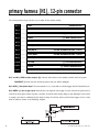
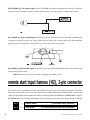
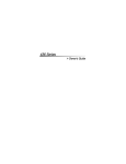
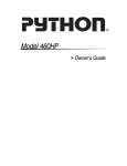
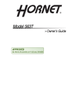
Model 516L
Installation Guide
®
© 2001 Directed Electronics, Inc. Vista, CA N516L 2-01
Rev. A. 1.1
table of contents
What is Included . . . . . . . . . . . . . . . . . . . . . . . . . . . . . . . . . . . . . . . . . . . . . . . . . . . . . . . . . . . . 3
Product Description . . . . . . . . . . . . . . . . . . . . . . . . . . . . . . . . . . . . . . . . . . . . . . . . . . . . . . . . . . 3
Primary Harness (H1), 12-Pin Connector. . . . . . . . . . . . . . . . . . . . . . . . . . . . . . . . . . . . . . . . . . . . 4
Remote Start Input Harness (H2), 2-Pin Connector
Other Plug-In Harnesses . . . . . . . . . . . . . . . . . .
System Feature Programming. . . . . . . . . . . . . . .
Dipswitch/Feature Settings . . . . . . . . . . . . . .
System Feature Descriptions . . . . . . . . . . . . . .
.
.
.
.
.
.
.
.
.
.
.
.
.
.
.
.
.
.
.
.
.
.
.
.
.
.
.
.
.
.
.
.
.
.
.
.
.
.
.
.
.
.
.
.
.
.
.
.
.
.
.
.
.
.
.
.
.
.
.
.
.
.
.
.
.
.
.
.
.
.
.
.
.
.
.
.
.
.
.
.
.
.
.
.
.
.
.
.
.
.
.
.
.
.
.
.
.
.
.
.
.
.
.
.
.
.
.
.
.
.
.
.
.
.
.
.
.
.
.
.
.
.
.
.
.
.
.
.
.
.
.
.
.
.
.
.
.
.
.
.
.
.
.
.
.
.
.
.
.
.
.
.
.
.
.
.
.
.
.
.
.
.
.
.
.
.
.
.
.
.
.
.
.
.
.
.
.
.
.
.
.
.
.
.
.
6
7
7
7
8
Recording User Programmable Messages . . . . . . . . . . . . . . . . . . . . . . . . . . . . . . . . . . . . . . . . . . . . 9
Voice Messages . . . . . . . . . . . . . . . . . . . . . . . . . . . . . . . . . . . . . . . . . . . . . . . . . . . . . . . . . . . . 10
Security Messages. . . . . . . . . . . . . . . . . . . . . . . . . . . . . . . . . . . . . . . . . . . . . . . . . . . . . . . . . 10
Remote Start Messages . . . . . . . . . . . . . . . . . . . . . . . . . . . . . . . . . . . . . . . . . . . . . . . . . . . . . 11
Silent Mode . . . . . . . . . . . . . . . . . . . . . . . . . . . . . . . . . . . . . . . . . . . . . . . . . . . . . . . . . . . . . . . 11
Public Address (P.A.) System . . . . . . . . . . . . . . . . . . . . . . . . . . . . . . . . . . . . . . . . . . . . . . . . . . . 12
Volume Adjustment . . . . . . . . . . . . . . . . . . . . . . . . . . . . . . . . . . . . . . . . . . . . . . . . . . . . . . . . . 12
Special Enhancement Feature . . . . . . . . . . . . . . . . . . . . . . . . . . . . . . . . . . . . . . . . . . . . . . . . . . . 12
Troubleshooting . . . . . . . . . . . . . . . . . . . . . . . . . . . . . . . . . . . . . . . . . . . . . . . . . . . . . . . . . . . . 13
Wiring Quick Reference Guide . . . . . . . . . . . . . . . . . . . . . . . . . . . . . . . . . . . . . . . . . . . . . . . . . . 16
Bitwriter™, Code Hopping™, DEI®, Directed™, Doubleguard®, ESP™, FailSafe®, Ghost Switch™,
Learn Routine™, Nite-Lite®, Nuisance Prevention Circuitry®, NPC®, Revenger®, Silent Mode™, Soft
Chirp®, Stinger®, Valet®, Vehicle Recovery System®, VRS®, and Warn Away® are all Trademarks or
Registered Trademarks of Directed Electronics, Inc.
2
© 2001 Directed Electronics, Inc. Vista, CA
what is included
■ Primary (H1) 12-pin harness
■ Remote start (H2) 2-pin input harness
■ Control module
■ Speaker p/n 518N
■ Plug-in LED harness
■ Plug-in program/record button harness
■ Plug-in microphone
product description
The 516L Voice Module is designed to add English or Japanese voice message capability to a vehicle security or
remote start system. It can be programmed to generate generic or Viper-specific messages in either English or
Japanese. The appropriate voice messages are generated by monitoring the host security or remote start system’s
input and output signals for the following functions: arming, disarming, Warn Away®, zone error, and zone violation.
The 516L can be adapted to most vehicle security systems by monitoring both the siren wire and the groundwhen-armed output or simply by monitoring the ground-when-armed output. When using the voice module with
most DEI systems, we recommend wiring and programming the 516L to monitor both the security system’s siren
output and ground-when-armed wire. Monitoring the siren output allows the full range of 516L features, along
with the alarm system’s Silent Mode feature, to be utilized with most DEI systems. The 516L is also capable of
adapting to many non-DEI security systems by wiring and programming the 516L to monitor only the groundwhen-armed output wire.
© 2001 Directed Electronics, Inc. Vista, CA
3
primary harness (H1), 12-pin connector
The primary harness plugs into the 12-pin socket of the control module.
H1/1
H1/2
H1/3
H1/4
H1/5
H1/6
H1/7
H1/8
H1/9
H1/10
H1/11
H1/12
______
______
______
______
______
______
______
______
______
______
______
______
GRAY
SPEAKER OUTPUT
GRAY
SPEAKER OUTPUT
BLUE
(-) HOOD/TRUNK INPUT
GREEN
(-) DOOR TRIGGER INPUT
BROWN
OPTIONAL SIREN INPUT
BLACK/WHITE
CUSTOM RECORDED MESSAGE 3 INPUT
RED/WHITE
CUSTOM RECORDED MESSAGE 2 INPUT
BLUE/WHITE
CUSTOM RECORDED MESSAGE 1 INPUT
ORANGE
GROUND-WHEN-ARMED INPUT
YELLOW
(+) 12V IGNITION INPUT
BLACK
RED
(-) CHASSIS GROUND INPUT
(+) 12V CONSTANT POWER INPUT
H1/1 and H1/2 GRAY speaker outputs (2): Connect these wires to the speaker provided with the system.
IMPORTANT! If these wires are shorted to ground, the unit will be damaged.
H1/3 BLUE (-) hood/trunk input: This wire responds to a (-) input with an instant trigger, ideal for hood/trunk pins.
H1/4 GREEN (-) door trigger input: Most vehicles use negative door trigger circuits. Connect the green wire to
a wire that shows ground when any door is opened. In vehicles with factory delays on the domelight circuit, there
is usually a wire that is unaffected by the delay circuitry. For vehicles with a positive door trigger circuit, a relay
must be added as shown in the following diagram:
4
© 2001 Directed Electronics, Inc. Vista, CA
H1/5 BROWN optional (+) siren input: This wire is used to monitor the siren chirps of an alarm system and
should only be connected if Silent Mode will be utilized. If you are using a DEI system, connect the H1/5 BROWN
wire to the (+) siren output of the DEI security system.
H1/6 BLACK WHITE, H1/7 RED/WHITE, and H1/8 BLUE/WHITE custom recorded multiplex inputs: These
three wires are multiplex sensor inputs. All three wires will function similarly, depending on whether the Siren
Monitoring feature (Feature 3) is programmed ON or OFF:
■ When the Siren Monitoring feature is programmed OFF: Inputs shorter than 0.8 seconds will activate the
“Triggered” message once, while inputs longer than 0.8 seconds will repeat the “Triggered” message six
times.
■ When the Siren Monitoring feature is programmed ON: Inputs shorter than 0.8 seconds will activate the
“Triggered” message once, while inputs longer than 0.8 seconds will repeat the “Triggered” message every 5
seconds until the siren resets.
NOTE: The “Violation” message has its own separate indication.
The wires are assigned to the following message numbers:
■ H1/6 BLACK/WHITE is used for Message 3 input.
■ H1/7 RED/WHITE is used for Message 2 input.
■ H1/8 BLUE/WHITE is used for Message 1 input.
H1/9 ORANGE armed input: Connect this input to the security system wire that supplies a (-) 500 mA ground
as long as the security system is armed. This output should cease as soon as the system is disarmed. When connecting the H1/9 wire to the ground-when-armed output of a security system that utilizes starter kill, the starter
kill relay must be isolated with a lamp diode (1N4004) to prevent ground feedback from the starter kill relay. See
the following diagram:
© 2001 Directed Electronics, Inc. Vista, CA
5
H1/10 YELLOW (+) 12V ignition input: The H1/10 YELLOW wire must be connected to the true (+)12V ignition
wire of the vehicle, whether the 516L is being interfaced with a security system or a remote start system.
H1/11 BLACK (-) chassis ground input: Remove any paint and connect this wire to bare metal, preferably with
a factory bolt rather than your own screw. (Screws tend to either strip or loosen with time.) We recommend
grounding all your components, including the siren, to the same point in the vehicle.
H1/12 RED (+) constant power input: Connect this wire to the positive battery terminal or to the constant 12V
supply to the ignition switch.
NOTE: Always use a fuse within 12 inches of the point you obtain (+)12V.
remote start input harness (H2), 2-pin connector
This harness and its connections are only required when wiring the 516L to a remote start system. The remote
start input harness plugs into the red 2-pin socket on the control module. When interfaced with a remote start
system, the 516L detects various remote start states by monitoring the H1/10 YELLOW, H2/1 ORANGE/BLACK, and H2/2
BLUE/BLACK wires, and in different combinations of wire activation, the 516L emits the appropriate voice message.
H2/1
H2/2
6
______
______
ORANGE/BLACK
BLUE/BLACK
(-) ACCESSORY INPUT (OPTIONAL)
(-) STATUS/SECOND IGNITION INPUT (OPTIONAL)
© 2001 Directed Electronics, Inc. Vista, CA
H2/1 ORANGE/BLACK (-) accessory input (optional): Connect the H2/1 ORANGE/BLACK wire to the (-) accessory output of the remote start system. This wire is located in the relay satellite ribbon harness on most DEI
remote start systems. The remote start accessory output will show ground as long as the remote start is activated,
except for a brief period when the system is cranking.
H2/2 BLUE/BLACK (-) status/second ignition input (optional): Connect this wire to the (-) status output or
(-) ignition output of the remote start system.
other plug-in harnesses
The status LED plugs into the white 2-pin socket. The program/record button plugs into the blue 2-pin socket of
the control module. There is also a phono-jack for the plug-in microphone.
system feature programming
dipswitch/feature settings
The 516L has selectable dipswitch settings for programming the system’s features. The four dipswitches are
located underneath the unit’s removable door. To select a system feature setting, simply move the dipswitch in the
direction of the arrow for the ON setting, or in the opposite direction for the OFF setting:
DIPSWITCH/FEATURE NUMBER
FEATURE
ON SETTING
OFF SETTING
ENGLISH
JAPANESE
VIPER
GENERIC
1
LANGUAGE
2
MESSAGE TYPE
3
SIREN MONITORING (BROWN WIRE)
ON
OFF
4
REMOTE START RUNNING MESSAGE
REPEATING
ONE TIME
© 2001 Directed Electronics, Inc. Vista, CA
7
system feature descriptions
FEATURE 1 - LANGUAGE: Dipswitch 1 is used to select either English or Japanese as the language in which the
voice messages and programming instructions will be announced.
FEATURE 2 - MESSAGE TYPE: Dipswitch 2 is used to select either Viper or generic voice messages. For example,
when programmed for the Viper setting the system would announce “Viper disarmed”, while a system programmed
with the generic setting would announce, “System disarmed.”
FEATURE 3 - SIREN MONITORING: Dipswitch 3 is used to turn the siren monitoring feature on or off. In the on
setting, the H1/5 BROWN wire monitors the siren wire of the security system so that the Silent Mode feature can
be retained. In the off setting, the H1/5 BROWN wire will not be monitored, and the system will always generate the armed voice message and error messages. In the off setting, the Silent Mode feature cannot be utilized.
FEATURE 4 - REMOTE START RUNNING MESSAGE: Dipswitch 4 is used to select either a repeating or one-time
“Caution, Valet operating vehicle” message to warn anyone near the vehicle that the Valet feature is running the
car. In the on setting, the message will repeat once every 60 seconds after the vehicle has been remote started.
In the off setting, the message will only be generated once.
8
© 2001 Directed Electronics, Inc. Vista, CA
recording user programmable messages
The 516L provides nine 5-second message slots to record user programmable messages for the three auxiliary trigger
inputs. These messages can be recorded and programmed using a learn routine. Depending on the language selected
by the position of Dipswitch 1, programming instructions will be announced in either English or Japanese to guide
the programmer through the steps of the recording learn routine.
To record a voice message using the learn routine:
1. Open one of the vehicle doors. (The GREEN door trigger input must be grounded.)
2. Turn on the ignition. (The YELLOW ignition input must be powered.)
3. Press and release the program/record button the number of times corresponding to whichever of the nine
5-second message slots you wish to record.
MESSAGE SLOT
NUMBER
MESSAGE INPUT WIRE
1
BLUE/WHITE input, zone error message
2
BLUE/WHITE input, triggered message
3
BLUE/WHITE input, zone violation message
4
RED/WHITE input, zone error message
5
RED/WHITE input, triggered message
6
RED/WHITE input, zone violation message
7
BLACK/WHITE input, zone error message
8
BLACK/WHITE input, triggered message
9
BLACK/WHITE input, zone violation message
ANNOUNCEMENT
4. Press and HOLD the program/record button. The unit will announce the number of the selected message slot
and you will then hear the word “recording”. The LED will turn on to indicate that the microphone is active and
that a 5-second message may now be recorded.
5. When you are finished recording a message, release the program/record button and the LED will go out. You
may also want to write down your custom recorded messages in the spaces provided in the table above.
© 2001 Directed Electronics, Inc. Vista, CA
9
voice messages
The voice messages described in this section will be in either English or Japanese, and either generic or Viperspecific, depending on how the 516L was programmed. Also note that if Siren Monitoring (Feature 3 in the System
Feature Programming section of this guide) has been programmed on, then Silent Mode may be activated and
voice commands may be eliminated for a single arming or disarming cycle.
security messages
Error messages: The following voice messages will be generated if there are errors in the respective zones:
SYSTEM STATE
MESSAGE GENERATED
Error detected on GREEN input
“Check doors”
Error detected on BLUE input
“Check hood or trunk”
Error detected on BLUE/WHITE input
Custom recorded error message for this input
Error detected on RED/WHITE input
Custom recorded error message for this input
Error detected on BLACK/WHITE input
Custom recorded error message for this input
While the system is armed: While the system is armed these voice messages will be generated for the respective system states:
SYSTEM STATE
MESSAGE GENERATED
System is armed/Siren input is activated once
Arm message
GREEN trigger input detected
“Intruder alert, door access”
BLUE trigger input detected
“Intruder Alert, hood or trunk access”
BLUE/WHITE trigger input detected
Custom recorded trigger message for this input
RED/WHITE trigger input detected
Custom recorded trigger message for this input
BLACK/WHITE trigger input detected
Custom recorded trigger message for this input
NOTE: If a dual-stage sensor is used, inputs shorter than 0.8 seconds will report the Warn Away/
Violation custom recorded message.
While the system is disarmed: When the system is disarmed, the disarm message will be heard. The 516L will
then recall any trigger inputs (up to 3) that were violated during the last arming cycle, and the voice messages
for the appropriate triggers will be generated:
10
© 2001 Directed Electronics, Inc. Vista, CA
SYSTEM STATE
MESSAGE GENERATED
System is disarmed/Siren input is activated twice
Disarm message
GREEN trigger input detected
“Door violation”
BLUE trigger input detected
“Hood or trunk violation”
BLUE/WHITE trigger input detected
Custom recorded trigger message for this input
RED/WHITE trigger input detected
Custom recorded trigger message for this input
BLACK/WHITE trigger input detected
Custom recorded trigger message for this input
remote start messages
The following messages will only be heard when using the 516L with a remote start system:
“Valet now starting engine, stand clear.” Once the remote start sequence is initiated, the voice module will
generate this message.
“Caution, Valet operating vehicle.” While the vehicle is running after having been remote started, the 516L
will generate this message every 60 seconds to warn anyone near the vehicle that the Valet is operating the
vehicle. If the 516L has been programmed to generate this message only once (Dipswitch #4 is in the off position, see System Feature Programming section of this guide), then this message will only be heard one time, 2
seconds after the H2/1 ORANGE/BLACK wire activates.
“Valet engine shutdown.” When the H1/10 YELLOW, H2/1 ORANGE/BLACK, and H2/2 BLUE/BLACK wires are all
deactivated, engine shutdown is indicated, and this message will be generated.
“Engine control manual.” If the H2/1 ORANGE/BLACK and the H2/2 BLUE/BLACK wires deactivate, but the
H1/10 YELLOW wire remains active, the 516L assumes that the customer has taken over operation of the vehicle
to drive it and will generate this voice message.
“Engine control Valet.” Anytime the H2/1 ORANGE/BLACK and the H2/2 BLUE/BLACK wire activate while the
H1/10 YELLOW input is already active, the unit will assume that Valet take-over is occurring and this message
will be generated.
silent mode
When the 516L is used in conjunction with most DEI security systems, Silent Mode can be used to temporarily
turn off the arm or disarm confirmation voice message before either arming or disarming the security system.
The confirmation message will then be eliminated for that one operation only.
© 2001 Directed Electronics, Inc. Vista, CA
11
In order to retain the Silent Mode feature in a DEI system that is being used with the 516L, the H1/5 BROWN
wire must be connected to the siren wire of the DEI system and Dipswitch #3, which controls the Siren
Monitoring feature, must be turned on. (See Feature Descriptions in the System Feature Programming section of
this guide.) The 516L monitors the siren output pulses to determine when to generate voice messages for the
arm and disarm commands. If siren pulses are not detected during the arming or disarming process, the 516L
will not send voice messages for these commands.
public address (p.a.) system
The public address function of the 516L can be used to talk to people outside of your vehicle. To use the public
address system, press and HOLD the program/record button. Wait for the LED light to illuminate steadily to enter
P.A. Mode. While in P.A. Mode, all sounds detected by the microphone will be amplified by the 516L and reproduced by the speaker.
NOTE: Before using the 516L in P.A. Mode, check local regulations regarding exterior speakers in
moving vehicles.
volume adjustment
The 516L has a volume adjustment knob on the side of the control module for controlling the speaker volume.
Simply turn the knob counter-clockwise to decrease the volume or clockwise to increase the volume.
special enhancement feature
In order to eliminate the chirp confirmation feature from a DEI security system but still retain the 516L
arm/disarm voice message confirmation, the component controlling siren chirps must be removed from the siren
module. (See the siren instructions of the DEI security system for details.)
If Silent Mode is desired, the chirp confirmation feature of the DEI security system cannot be programmed to
the OFF setting when interfacing with the 516L. When the 516L’s Siren Monitoring feature is in the ON setting,
the unit relies on pulses from the security system’s siren output to indicate arm/disarm confirmation. If the security system’s chirp confirmation feature is programmed OFF, the 516L cannot detect the siren chirps, and
therefore the arming and disarming commands will be ignored.
12
© 2001 Directed Electronics, Inc. Vista, CA
troubleshooting
The 516L does not report arming and disarming messages:
■ Is the 516L ground-when-armed input wire connected to the security system’s ground-when-armed output?
The 516L does not report arming and disarming messages, but when the vehicle ignition key is turned off,
the 516L reports the disarming message:
■ If the security system has starter kill, the starter kill relay must be isolated with a 1-amp diode (1N4004).
(See H1/9 ORANGE armed input description in the Primary Harness (H1), 12-Pin Connector section of this guide.)
When interfaced with the 516L, the DEI security system will not perform Silent Mode:
■ Has Channel 2 of the security system been programmed?
■ The 516L’s optional H1/5 BROWN siren input wire and the H1/9 ORANGE ground-when-armed input must be
connected to the security system.
■ Make sure that Dipswitch #3 (Siren Monitoring) on the 516L is in the on position. (See Dipswitch/Feature
Settings section of this guide.)
When the vehicle is remote started the 516L does not announce, “Valet now starting, stand clear”:
■ The H1/10 YELLOW wire of the 516L should be connected to the true ignition wire of the vehicle and NOT to
an accessory wire.
■ The H1/10 YELLOW wire must read (+)12V ignition while the vehicle is remote started.
■ Make sure that the H2/1 ORANGE/BLACK and H2/2 BLUE/BLACK wires are properly connected to the remote
start system. (See the Remote Start Input Harness (H2), 2-Pin Connector section of this guide.)
The 516L does not report the status of the remote starter while the vehicle is remote started:
■ Make sure that the H2/1 ORANGE/BLACK and H2/2 BLUE/BLACK wires are properly connected to the remote
start system. (See the Remote Start Input Harness (H2), 2-Pin Connector section of this guide.)
© 2001 Directed Electronics, Inc. Vista, CA
13
notes
14
© 2001 Directed Electronics, Inc. Vista, CA
notes
© 2001 Directed Electronics, Inc. Vista, CA
15
wiring quick reference guide
16
© 2001 Directed Electronics, Inc. Vista, CA