1
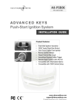
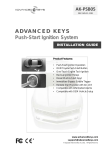
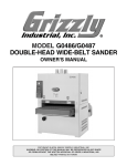
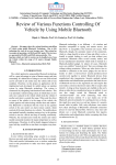
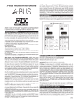
AK-105
REV: A05-12-1217
A D VA N C E D K E Y S
Smart Keyless Entry System
INSTALLATION GUIDE
Product Features:
•
•
•
•
•
•
•
•
•
•
•
•
•
*
Smart Keyless Locking/Unlocking
Compact Sized Smart Keys
Dual-Antenna Setup
Bypass Transponder RFID Cards
Vehicle Anti-Theft Function
Shock Sensor Alarm / Unlock
Ignition Controlled Lock / Unlock
Auto Vehicle Battery Power Saving
Door-Not-Closed Reminder
Smart Key Battery Low Reminder
Locking-Delay Function
Compatible with Push-Start Ignition
Auto Window Closing / AUX Output
www.advancedkeys.com
[email protected]
© Copyright Advanced Keys Inc. 2013. All Rights Reserved.
TABLE OF CONTENTS
Table Of Contents ..................................................................................... 2
Product Contents ..................................................................................... 2
Warning and Safety Information ............................................................ 3
Safety Precautions ................................................................................ 3
Pre-installation Considerations ............................................................. 3
Connections ............................................................................................... 4
Controller Wiring Diagram .................................................................... 4
Main Harness Wire Descriptions .......................................................... 5
Access Harness Wire Descriptions ..................................................... 6
Installation ................................................................................................... 7
Installation Overview ............................................................................. 7
Installation Note .................................................................................... 7
Programmable Features ........................................................................ 7
Antenna Installation ............................................................................... 8
Frequent Asked Questions ..................................................................... 9
Smart Key Programming Procedure ..................................................... 10
Closing Up .................................................................................................. 11
References Information ............................................................................ 11
Specifications ....................................................................................... 11
Product Registration ............................................................................. 11
Warranty ............................................................................................... 12
FCC And Canadian Compliance .......................................................... 12
PRODUCT CONTENTS
The following list of components are included in this system:
1
2
1
1
1
1
1
2
– Control Unit
– Smart Key Fob
– Main Harness (8-Pin)
– Accessory Harness (7-Pin)
– Dual Colour LED Indicator
– Front Antenna Coil
– Rear Antenna Coil
© Copyright Advanced Keys Inc. 2013. All Rights Reserved.
1
2
1
1
1
–
–
–
–
–
Bypass Antenna
Bypass Transponder Card
Shock Sensor
Starter Disable Relay
User Manual/Installation Guide
WARNING AND SAFETY INFORMATION
PRODUCT SAFETY AND LEGAL DISCLAIMER
• This product shall be installed by a certified technician therefore a certain level
of competence and knowledge are therefore assumed when reading this guide.
• This guide is provided as a GENERAL installation instructions and vehicle
subjected to installation maybe different.
• This product is designed based on vehicle regulatory standard. Please observe
your local public road traffic law and regulations prior to installation.
• Exercise due-diligence when installing this product. The manufacturer and
distributors of this product will not accept any vehicle damage or personal
injury resulting from the installation of this product. Installation of this product is
acceptance of this statement and releases the manufacturer/distributors of this
product from any direct or indirect liabilities.
• Once installation is complete, please return this guide along with other
documentations included in this product back to the customer for future
reference. The manufacturer/distributors of this product does not guarantee
this particular version will be available at a later date.
PRE-INSTALLATION CONSIDERATIONS
• Carefully read and understand the User Manual, Installation Guide and
Electrical Service Information for the subjected vehicle before begin work.
• Install in a well-lit, dry, covered area away from the elements and keep at least
one window open at all time during installation. Do not leave key inside ignition
switch and /or detection range. Prepare all tools required for the installation.
Special tools maybe necessary depending on vehicle.
• Verify the vehicle has proper grounding and does not have any outstanding
electrical/functional issue prior to installation.
• To avoid short circuit, it is recommended to pull-out related fuses before
installation and put them back when installation is complete.
• Only locate necessary wires related to the installation (most required wiring are
under driver dash/kick panel areas) and connect to the unit according to the
wiring diagram. Use a Multimeter to verify and confirm wire’s function, polarity
before connecting or disconnecting. We strictly prohibit testing or modifying
the vehicle’s ECU, airbag and ABS systems.
• Begin function tests on the system after verifying and ensuring all wires have
been connected correctly and insulated properly.
CAUTION
DO NOT power up the module before it is properly grounded.
Should the unit be powered before being grounded, serious
damage to internal components could occur.
© Copyright Advanced Keys Inc. 2013. All Rights Reserved.
3
CONNECTIONS
CONTROLLER WIRING DIAGRAM
JP1
JP2
JP3
Jumper Settings:
JP4
Default Settings
Optional Settings
JP1
Neg.(-) Door Trigger
Pos.(+) Door Trigger
JP2
Ground-When-Armed
Ground-When-Disarmed
JP3
Single Unlock Pulse
Double Unlock Pulses
JP4
Horn Output
Siren Output
Legend:
Input
+ Positive Type
Output
Negative Type
~ Frequency Type
-
Brown
Trunk Release
Main Harness
8-Pin 18 AWG
Grey
7.5A
Parking Light
Grey
7.5A
Parking Light
Red
15A
Battery +12V
Green
15A
Lock
Blue
15A
JP3
Black
JP4
Blue (26 AWG)
7-Pin 22 AWG
Accessory Harness
JP2
Shock Sensor
Starter Kill Relay Control
Purple
Push-Start Module Control
Brown
Brake
Blue
Green
Unlock
Ground
Purple
White
In-Line Fuse
Window Closer Module Control
JP1
Door Switch
Red
ACC
Horn Control
+
+
+
-
~
+
-+
Shock
Sensor
+
Dual Color LED
Front Antenna
Rear Antenna (Longer Wire)
Bypass Antenna
WARNING: Manufacturer/Distributors of this product will not be responsible for any electrical damage resulting from
improper installation of this product, be that either damage to the vehicle itself or to the device. This device must be
installed by a certified technician for this guide has been written for properly trained technicians; a certain level of
skill & knowledge is therefore assumed. Review this installation guide and vehicle's service manuals before install.
4
© Copyright Advanced Keys Inc. 2013. All Rights Reserved.
JP1
JP2
JP3
JP4
Main Harness
8-Pin 18 AWG
MAIN HARNESS WIRING DESCRIPTIONS
Brown
Grey
7.5A
Trunk Release
Parking Light
Grey
7.5A
Parking Light
Red
Green
15A
Battery +12V
Lock
Blue
15A
15A
JP3
Black
Unlock
Ground
Purple
JP4
Horn Control
+
+
+
-
Wiring Description:
Brown OUTPUT
̶
500mA Trunk Release
Connect to the negative side of the trunk release trigger. This output will provide 1 second pulse
when UNLOCK button is pressed for 2 seconds. (This function is disabled when ACC input is ON)
Grey
OUTPUT
+
7.5A
2x Parking Light
Connect to the positive side of left/right parking lights or the hazard light switch for same effect.
Red
INPUT
+
15A
Battery +12V
Connect to a +12v source. Ensure that the OEM source wire used is fused for more than 15A.
Note: When no suitable +12V source available (where current capacity is less than 15A) use
vehicle’s interior fuse junction box or route directly from battery B+ connection.
Green
̶
OUTPUT
15A
Lock
Connect this output directly to the negative-triggered door lock signal wire.
Blue
̶
OUTPUT
15A
Unlock
JP3
Connect this output directly to a negative-triggered door unlock signal wire.
Note: This system outputs a single unlock pulse by default. Jumper (JP3) provides a double unlock
pulses output option for vehicles that require a two consecutive unlock-pulse to unlock/disarm or to
bypass the Driver Door Priority Unlock function to unlock all doors.
Black
̶
INPUT
15A
Ground
Connected to a bare, unpainted metal part of the vehicle chassis. It is recommended to use a
factory ground point bolt rather than a self-tapping screw. Screws tend to loosen or rusted over
time and leading to erratic electrical problems.
Purple OUTPUT
̶
500mA Horn Control
JP4
Negative (-) to Positive (+)
Connect to the negative side of horn for audio notification.
Output Conversion
Note: This system is programmed for muted Lock/Unlock
Horn
operation by default. If audio notification is desired for arming
85
87
and disarming; connect Horn Control output to a siren* and Control
NO
Output
30
change the jumper setting (JP4) to Siren Output option
COM
(-)
(Refer to Horn or Siren Mode in Programmable Features).
NC
86
87A
Note: If siren control is a positive type or require more than
500mA to operate; add a relay according to the diagram on +12V
the right to convert output to a positive type.
*Siren not included
© Copyright Advanced Keys Inc. 2013. All Rights Reserved.
5
ACCESSORY HARNESS WIRING DESCRIPTIONS
JP1
JP2
JP3
JP4
Accessory Harness
7-Pin 22 AWG
Blue (26 AWG)
White
Purple
Shock Sensor / Unlock
OPTIONAL
REQUIRED
JP2
Push-Start Module Control
OPTIONAL
Brown
Blue
~
Brake
REQUIRED
OPTIONAL
-
Starter Kill Relay Control
+
Window Closer Module Control
Green
JP1
REQUIRED
Red
-+
Door Switch
ACC
REQUIRED
+
Ensure all connections are completed and properly secured
prior to connecting the wire harnesses to the module.
Wiring Description:
INPUT
Blue
̶
NOTE
(26 AWG) Shock Sensor / Unlock Input
OPTIONAL
Connect to the optional Shock Sensor or to a manual unlock trigger input. (See Programmable Features)
White
OUTPUT
̶
500mA Starter Kill Relay Control
(Starter Kill Relay is not required if installed with AK-PSB05)
Depending on jumper (JP2) selection this output can be used for:
Starter Kill Relay Control (Default) – Also known as GroundWhen-Armed. While armed (Smart Key not detected or LOCK
button pressed) this output provide a GND signal to disable the
starter circuit only when alarm is triggered. Connect the Starter Kill
Relay according to the wiring diagram on the right.
Ground-When-Disarmed – Provides a GND signal while disarmed.
(Smart Key is detected or UNLOCK button pressed) This output can
be used as an enable signal to an immobilizer bypass or known as
Ground-When-Running. Alternatively this output can connect to any
system that requires an input signal when a Smart Key is sensed.
Purple OUTPUT
~
JP2
OPTIONAL
Starter Kill Relay (Included)
Starter
Kill Relay
Control
85
86
87
NO
COM
NC
30
87A
START (+)
ON
ENGINE
START
ACC
OFF
100mA Push-Start Module Control
OPTIONAL
Connect to the “Controller Enable Input” on the optional Engine Push-Start Ignition Controller.
This output provides an encrypted signal to the Engine Push-Start Ignition controller only when system sense a
valid Smart Key or disarmed via the UNLOCK button or from the Bypass Transponder Card.
Brown
INPUT
+
Brake
REQUIRED
Connect to the brake pedal switch that output +12v when brake is applied, GND or float when released.
Note: This input is required for Smart Key programming and Ignition-Controlled Lock function.
Blue
̶
OUTPUT
100mA Window Closer Module Control / AUX
OPTIONAL
Connect to the optional Auto Window Closer Module trigger input. Alternately it can be used as a remote
activated auxiliary output, see more on Programmable Features section on configure this auxiliary output.
Green
INPUT
̶
Door Switch
JP1
REQUIRED
Door
Connect to vehicle’s negativeSwitch
Door
Dome
Input
triggered “door open” signal wire
Switch
Light
directly. Change jumper (JP1) to
+12v
Positive Door Trigger if door
switch is a positive-triggered type.
(Default) Negative Door Trigger (-)
Red
INPUT
+
ACC
© Copyright Advanced Keys Inc. 2013. All Rights Reserved.
Door
Switch
+12v
Positive Door Trigger (+)
REQUIRED
**Required for System Operation** This input must be connected to a
+12v source when vehicle is running. Note: With this input active,
controller will stop search for the Smart Keys to conserve key’s battery
and avoid unintended lock actuation while the vehicle is running.
6
Door
Switch
Input
Dome
Light
ACC
Input
VEHICLE
CIRCUIT
START
ON
ACC
OFF
INSTALLATION
INSTALLATION OVERVIEW
Use following steps as a guide to install this system:
Review product manual
and vehicle’s electrical
manual. Prepare vehicle
for installation.
Review and set
controller jumper
settings according to
requirements.
Connect Main and
Accessory Harness.
Pre-position antennas
and antenna wiring.
Mount LED, secure
controller and close-up
installation.
Verify smart keys and
bypass transponder card
function/range then route
and secure antennas to
final position.
Power ON the system
and set programmable
features.
INSTALLATION NOTES
• For vehicles equipped with factory or aftermarket alarm/remote start, it is
possible to install this system without the anti-theft alarm and remote start
functions. (Refer to User Manual on disabling Alarm Function) Connect only
Battery, Ground, Lock, Unlock, ACC, Brake, Door Switch and Antennas for
basic Smart Keyless Entry function only.
• Ensure the ACC input is properly connected. It is required for remote-start
function and to conserve the Smart Key’s battery while vehicle is running.
Avoid leaving the Smart Key inside the detection range for extended periods
of time, this will shorten Smart Key’s battery life as authentication stays
constant between smart key and controller when ignition is off.
• It is highly recommended to connect the Door Switch input to the vehicle.
This input is required for adjust user programmable functions and system will
have a better remote sensing performance when it aware of the door status.
PROGRAMMABLE FEATURES
The following features can be adjusted according to customer’s requirements:
Horn or Siren Mode
Under default JP4 “Horn Output” state; system will stay muted when locking and
unlocking. Horn output will only sound in alarming and in programing modes.
If the customer desires audio chirp notifications for vehicle’s arming status,
connect a siren to the horn output (see Wiring Description) and change JP4 to
“Siren Output” setting. Siren and Parking Lights outputs behave as following:
Unlock
Lock
Remote Start
Horn Output
Siren Output
Parking Light
-
2x
1x
1x
2x
1x
1x
© Copyright Advanced Keys Inc. 2013. All Rights Reserved.
7
PROGRAMMABLE FEATURES (CONT.)
Ignition-Controlled Door Lock
Enabled by default and controlled by Brake input, this function will provide:
• Auto Door Locking when ACC is turned ON while brake is applied.
• Auto Door Re-Locking when brake applied after door opened-then-closed.
• Auto Door Unlocking when ACC is OFF.
To disable/ enable Ignition-Controlled Door Lock feature: Disconnect the Main
harness (powering OFF the controller) then press and hold the brake pedal (apply
+12v to Brake input) then reconnect the Main harness (powering ON the controller).
Horn output will sound 2x if this feature is disabled or 1x if enabled.
Shock Sensor Function
Optional Dual-Stage Shock Sensor can be installed to provide additional security.
(See User Manual for operation) Install the shock sensor near the center of the
vehicle to sense vibrations from both the front and the back. Peel the adhesive and
attach it to the vehicle’s chassis (metal) surface. Test the shock sensor's sensitivity by
applying light impact from all sides of the vehicle, adjust if necessary. Keep in mind
that increased sensitivity would yield more false alarms.
The Shock Sensor Input can be programmed (See User Manual) to accept a Ground
signal that triggers Door Unlock function while the Smart Key remote is in the range:
• User have the option to set the system to unlock doors only when the shock
sensor is triggered. This is useful for vehicle with shaved door handles or for user
that prefer manually unlocking doors by a slight “tap/knock” on the driver door. To
use this function, set shock sensor sensitivity to max and mount it close to the
trigger area where user might be “tap/knock” on.
• Alternatively, connect the Shock Sensor/Unlock Input to an external Ground
trigger switch that is mounted on the door handle to activate Unlock manually.
Auxiliary Output (Via Remote Start Button)
If Smart Key system is a stand-alone installation (without Push-Start) or the remote
start function is not required, the Blue (22AWG) “Window Closer Module Control”
output can be programmed as an auxiliary output (See User Manual). Press-and-hold
the Remote Start Button will produce a 1 second (-)negative pulse for triggering an
external device.
Note: Once in AUX mode, Auto Windows Closer will not function automatically when locking/arming.
ANTENNAS INSTALLATION
Antennas should be mounted on a Non-Enclosed and Non-Metallic material such as
clear glass or plastic trim panels. Recommended placements for the Front-Antenna is
on the top-left corner of the front windshield and bottom-left corner of the rear
windshield for the Rear-Antenna. The Bypass-Antenna can be placed around the
edge of the front windshield so it can sense the Bypass Transponder Card within one
inch away from outside of the vehicle. Do not place antenna in locations that will be
shield by metallic material.
Test for coverage and range after installation to determine the optimal locations for
the antennas. You may adjust antenna positions to other possible placement locations
as illustrated in the diagram next page. Use double sided tape to secure antennas
after final positions are confirmed.
8
© Copyright Advanced Keys Inc. 2013. All Rights Reserved.
ANTENNAS INSTALLATION (CONT.)
Rear Antenna
Placement
Main Antennas
5 - 6 Feet Range
IMPORTANT
Front Antenna
Placement
Bypass Antenna
0.5 - 1 Inches Range
Bypass Antenna
Placement
Other Possible
Placement Locations
Antenna needs to be positioned away from any type of
metallic material to achieve the best reception in all
directions. Avoid strain/pull on antenna wiring and do
not bend or overlap Main antenna with Bypass antenna.
FAQ
Why is key detection not working or the range is very sort?
Verify antenna position: Antenna may be on or close to metallic material, change
position to verify range sensitivity. Check antenna wiring, do not pull on the
antenna wires, make sure connectors are firmly seated. If remote failed to work
both in proximity and manually press the buttons, follow key programming
procedure to relearn all keys.
What does each LED color status mean?
See User Manual for more information on LED status detail.
How to install this system without the alarm function?
See User Manual for more information on disable alarm function.
How to enable/disable automatic door locking/unlocking function?
Please follow “Ignition-Controlled Door Lock” under the programmable features
section to enable/disable this function.
How does Remote Start button on the Smart Key remote work?
Remote Start function require installing the optional Advanced Keys Push-Start
System (AK-PSB05). Press the remote start button will send a remote start
signal to the Push-Start Module via the Push-Start Module Control output. Please
refer to Push-Start Installation manual for more info on remote start the vehicle.
© Copyright Advanced Keys Inc. 2013. All Rights Reserved.
9
KEY PROGRAMMING PROCEDURE
If required, use following procedures to pair a new set of Smart Key and/or Bypass
Transponder Cards. Both sets of Smart Keys or the Bypass Transponder Cards must be
present and accessible during programming.
Enter Programming Mode
Disarm the system with a valid Smart Key or Bypass Transponder Card.
With Ignition Key – Turn the Ignition Key to the ACC position. After few seconds switch
the Ignition Key to OFF position and immediately back to ACC position for five times or as
following: OFF–ACC–OFF–ACC–OFF–ACC–OFF–ACC–OFF–ACC. Keep the Ignition
Key in ACC position at the fifth time and the horn will sound twice.
With Push-Start Button – Cycle ignition five times by press the Push Button OFF to
ACC state first then after a few seconds quickly toggle the Push-Start button as follow:
ON–OFF–ACC–ON–OFF–ACC–ON–OFF–ACC–ON–OFF–ACC–ON–OFF–ACC.
Note: Switch Ignition to OFF at any time will exit the programming mode with horn sound
three times
Smart Key(s) Programming
1. After enter the Smart Key programming mode, LED indicator turns RED. You have a
30-second window to program. If you do not wish to program Smart Keys, press the
brake pedal once to skip to Bypass Transponder Cards programming (Horn will sound
once to confirm)
2. Press and hold the LOCK button on the first Smart Key until horn sound once.
3. Press and hold the LOCK button on the second Smart Key until horn sound once.
4. Smart Keys programming is now completed. System will automatically enter Bypass
Transponder Cards programming mode.
Bypass Transponder Cards Programming
1. After enter the Bypass Transponder Card programming mode, LED indicator turns
BLUE. You have a 12-second window to program. To skip Bypass Transponder Cards
programming, press the brake pedal once will end the programming mode with horn
sound five(5) times.
2. Hold first Bypass Transponder Card against the reading field of the Backup Antenna
until the horn sound once.
3. Repeat for the second Bypass Transponder Card until the horn sound five(5) times to
indicate key programming has been successfully completed.
Note: Only one Bypass Transponder Card should be present in the reading field at a time.
The sensing range for the Bypass Antenna is under an inch.
Horn Sound Summary Table
10
Number of Horn Sound
Mode Description
1x
Remote / Key Registered
2x
Entered Programming mode
3x
Programming failed
5x
Programming successful
© Copyright Advanced Keys Inc. 2013. All Rights Reserved.
CLOSING UP
• Connecting the wire harnesses and power ON the controller, check and confirm system operations
(Refer to User Manual) then verify functions of the vehicle are in working order.
• Make sure all wiring connection are insulated properly. Place and secure control units to locations
inside trim panels and bundle all lose wiring. Put back all trim panels
• When mounting the controller unit in the vehicle, consider the location carefully. You should make
sure that you avoid any location where the controller is exposed to moisture, extreme heat or
interfere with moving parts on the vehicle which hampers driving.
• Explain all functions related to the end-user of this system.
REFERENCES INFORMATION
PRODUCT SPECIFICATIONS
Controller operating voltage range: .................................................................................... 10 VDC – 16 VDC
Controller Stand by power: ................................................................................................. ≤ 30mA @ 12 VDC
Avg. controller operating power: ........................................................................................... ≤ 80mA@12VDC
Devices operating temperature range: ..................................................................................... -25°C – +85°C
Transmitter operating voltage range: ...................................................................................... 2 VDC – 4 VDC
Transmitter Stand by power: ................................................................................................... ≤ 7 µA @ 3 VDC
HF operation frequency and range: ............................................................... 433.92MHz @ 25 - 30 Meters
LF operation frequency and range: .................................................................... 134.2 KHz @ 1.5 - 2 Meters
Smart Key Fob Dimensions: ................................................................................. 65mmL x 44mmW x 6mmH
Base Controller Dimensions: ........................................................................... 115mmL x 90mmW x 30mmH
PRODUCT REGISTRATION
Installer of this system to is requested to fill out the following information as a proof of installation to
the end-user of this system. For manufacture warranty to take immediate effect please request the
end-user to update the following information at: http:// www.advancedkeys.com/registration.htm
Company / Installer Name:
Phone Number:
Installer Address:
Date of Installation:
Vehicle Manufacture:
Model:
Year:
Front Antenna Location:
Rear Antenna Location:
Bypass Antenna Location:
Interface/Bypass Module Used: YES
If YES specify bypass make/model:
NO
All Smart Keys and Bypass Cards Working: YES
Push-Start Module Installed:
Antenna Mounted on Windshields:
YES
YES
Reviewed Product Operation with End-User: YES
NO
NO
NO
NO
Additional Comments:
© Copyright Advanced Keys Inc. 2013. All Rights Reserved.
11