
1
CAV6.6
Six-Zone, Six-Source
Audio-Video Controller Amplifier
INSTRUCTION MANUAL
IMPORTANT SAFEGUARDS
9. Heat - The appliance should be situated away from heat sources such
as radiators, heat registers, stoves, or other appliances (including
amplifiers) that produce heat.
10.Power Sources - The appliance should be connected to a power supply
only of the type described in the operating instructions or as marked on
the appliance.
WARNING: TO REDUCE THE RISK OF FIRE OR ELECTRIC SHOCK,
DO NOT EXPOSE THIS APPLIANCE TO RAIN OR MOISTURE.
11.Grounding or Polarization - Precaution should be taken so that the
grounding or polarization means of an appliance is not defeated.
CAUTION: TO REDUCE THE RISK OF ELECTRIC SHOCK, DO NOT
REMOVE COVER. NO USER - SERVICEABLE PARTS INSIDE.
REFER SERVICING TO QUALIFIED SERVICE PERSONNEL.
12.Power Cord Protection - Power supply cords should be routed so that
they are not likely to be walked on or pinched by items placed upon or
against them, paying particular attention to cords at plugs, receptacles,
and the point where they exit from the appliance.
The lightning flash with arrowhead symbol, within an equilateral
triangle, is intended to alert the user to the presence of uninsulated
“dangerous voltage” within the product’s enclosure that may be of
sufficient magnitude to constitute a risk of electric shock to persons.
The exclamation point within an equilateral triangle is intended to
alert the user to the presence of important operating and maintenance (servicing) instructions in the literature accompanying the
appliance.
POWER CORD NOTICE FOR INTERNATIONAL OPERATION
For 230V, 50Hz operation please select the power cord for your
area. Select the plug for your area at one end and a IEC320 connector at the other. It is not necessary to make any other
changes. If you have any questions please call Russound Inc. at
1-800-638-8055 or 603-659-5170
Safety Instructions:
1. Read Instructions - All the safety and operating instructions should be
read before the appliance is operated.
2. Retain Instructions - The safety and operating instructions should be
retained for future reference.
3. Heed Warnings - All warnings on the appliance in the operating instructions should be adhered to.
4. Follow Instructions - All operating and user instructions
should be followed.
5. Water and Moisture - The appliance should not be
used near water; for example, near a bathtub, washbowl, kitchen sink, laundry tub, in a wet basement,
or near a swimming pool.
6. Carts and Stands - The appliance should be used only
with a cart or stand that is recommended by the manufacturer. An
appliance and cart combination should be moved with care. Quick
stops, excessive force and uneven surfaces may cause the appliance
and cart combination to overturn.
7. Wall or ceiling Mounting - The appliance should be mounted to a wall
or ceiling only as recommended by the manufacturer.
8. Ventilation - The appliance should be situated so that its location or
position does not interfere with its proper ventilation. For example, the
appliance should not be situated on a bed, sofa, rug, or similar surface
that may block the ventilation openings, or placed in a built-in installation, such as a bookcase or cabinet that may impede the flow of air
through the ventilation openings.
2
13.Cleaning - The appliance should be cleaned only as recommended by
the manufacturer.
14.Non-use Periods - The power cord of the appliance should be
unplugged from the outlet when left unused for a long period of time.
15.Object and Liquid Entry - Care should be taken so that objects do not
fall and liquids are not spilled into the enclosure through the openings.
16.Damage Requiring Service - The appliance should be serviced by qualified service personnel when:
A. The power supply cord or the plug has been damaged; or
B. Objects have fallen, liquid has been spilled into the appliance; or
C. The appliance has been exposed to rain; or
D.The appliance does not appear to operate normally; or
E. The appliance has been dropped or the enclosure is damaged.
17.Servicing - The user should not attempt to service the appliance beyond
that described in the operating instructions. All other servicing should
be referred to qualified service personnel.
Precautions:
1. Power – WARNING: BEFORE TURNING ON THE POWER FOR THE
FIRST TIME, READ THE FOLLOWING SECTION CAREFULLY.
All models are designed for use with either AC120V, 60Hz or AC240,
50Hz voltages. The unit will autoswitch to either of these voltages
2. Do Not Touch The CAV6.6 With Wet Hands – Do not handle the CAV6.6
or power cord when your hands are wet or damp. If water or any other
liquid enters the CAV6.6 cabinet, take the CAV6.6 to a qualified service
person for inspection.
3. Location of CAV6.6 – Place the CAV6.6 in a well - ventilated location.
Take special care to provide plenty of ventilation on all sides of the
CAV6.6 especially when it is placed in an audio rack. If ventilation is
blocked, the CAV6.6 may overheat and malfunction. Do not expose the
CAV6.6 to direct sun light or heating units as the CAV6.6 internal components temperature may rise and shorten the life of the components.
Avoid damp and dusty places.
4. Care – From time to time you should wipe off the front and side panels
of the cabinet with a soft cloth. Do not use rough material, thinners,
alcohol or other chemical solvents or cloths since this may damage the
finish or remove the panel lettering.
TABLE OF CONTENTS
USER SECTION
Product Introduction....................................................................................................................................................5
Component Guide
CAV6.6 Controller (Front panel operation)..............................................................................................................6-7
UNO-S2 Keypad .....................................................................................................................................................8
UNO-TS2 Touchscreen ............................................................................................................................................9
UNO-S1 Keypad ...................................................................................................................................................10
SRC2 Remote Control...........................................................................................................................................11
Operation
UNO-S2 Keypad Button Functions..........................................................................................................................12
UNO-S2 User Menu - Setting Preferences...............................................................................................................13
UNO-S1 Keypad Button Functions..........................................................................................................................14
UNO-S1 User Menu - Setting Preferences...............................................................................................................15
UNO-TS2 Touchscreen Button Functions ................................................................................................................16
UNO-TS2 - Setting Preferences..............................................................................................................................17
INSTALLER SECTION
Getting Started
Unpacking ...........................................................................................................................................................18
System Components ............................................................................................................................................18
Tools Needed.......................................................................................................................................................18
System Installation Considerations.........................................................................................................................18
Connection Tips ...................................................................................................................................................18
Component Guide
CAV6.6 Controller Front Panel ...............................................................................................................................19
CAV6.6 Controller Rear Panel ...........................................................................................................................20-21
UNO Keypad OS Update Port ................................................................................................................................22
UNO Keypad Rear Panel .......................................................................................................................................23
Wiring Instructions
Keypad Wiring......................................................................................................................................................24
Speaker Wiring ....................................................................................................................................................24
UNO-S2 Keypad Installation
Keypad Connections.............................................................................................................................................25
IR Receiver Connection .........................................................................................................................................26
Keypad Location ..................................................................................................................................................27
Keypad Installation ...............................................................................................................................................27
Making Connections
UNO Keypad Port Connection ...............................................................................................................................28
Source Audio/Video Input Connections ..................................................................................................................29
Source Audio/Video Loop Output Connection .........................................................................................................30
Speaker Connections............................................................................................................................................31
Accessory IR Connection ......................................................................................................................................32
Zone Audio/Video Outputs ....................................................................................................................................33
A-BUS Ready Sub-zone Connection ........................................................................................................................34
12VDC Trigger In/Out
Home Theater Trigger In ..................................................................................................................................35
50mA Trigger Out............................................................................................................................................35
Page Trigger In/Out ....................................................................................................................................36-37
Page Audio/Video In....................................................................................................................................36-37
Zone Trigger Out .............................................................................................................................................38
3
TABLE OF CONTENTS
RNET Link In/Out - Multiple Controllers...................................................................................................................39
RNET Link In/Out - RNET-enabled Components .......................................................................................................40
RS-232 Interface ..................................................................................................................................................41
Programming Center Keypad Port Connection........................................................................................................42
Initial Install Test .......................................................................................................................................................43
Programming
System Programming Overview ........................................................................................................................44-45
Source Information Form ......................................................................................................................................46
Zone Information Form .........................................................................................................................................47
Macro Editor Form ...............................................................................................................................................48
Installation Menu..............................................................................................................................................49-61
Installation Menu Overview ...............................................................................................................................49
Source Setup .............................................................................................................................................50-56
Basic Setup ..............................................................................................................................................50-51
Zone Setup ................................................................................................................................................56-57
Controller Setup ..............................................................................................................................................57
Power Management ....................................................................................................................................57-59
Learn IR .....................................................................................................................................................59-60
Macro Editor ..............................................................................................................................................60-61
System Info.....................................................................................................................................................61
Setup Menu Flow Charts..............................................................................................................................62-72
Basic Setup .................................................................................................................................................62
Key Configuration .........................................................................................................................................63
Source Names/Volume Trim..........................................................................................................................64
Numeric IR...................................................................................................................................................65
Source Select/Number of Sources ................................................................................................................66
Zone Setup ..................................................................................................................................................67
Controller Setup ...........................................................................................................................................68
Power Management......................................................................................................................................69
Learn IR.......................................................................................................................................................70
Macro Editor ................................................................................................................................................71
System Info..................................................................................................................................................72
REFERENCE SECTION
Keypad Diagnostic Menu ...........................................................................................................................................73
IR Device Code List ..............................................................................................................................................74-77
Source Names List...............................................................................................................................................78-79
Sample System Configurations
1 -Six Zones and Six Sources ...........................................................................................................................80-81
2 - Integrate Multiple CAV6.6's .........................................................................................................................82-83
3 - Zone Keypad Expansion ..............................................................................................................................84-85
4 - A-BUS Ready Sub-zone Addition ...................................................................................................................86-87
5 - Additional Amplification ...............................................................................................................................88-89
6 - Home Theater ............................................................................................................................................90-91
IR Key Code List ................................................................................................................................................92-113
Technical Specifications...........................................................................................................................................114
Warranty ................................................................................................................................................................115
4
PRODUCT INTRODUCTION
Thank you for choosing the Russound® CAV6.6 controller amplifier to enhance your home with distributed audio and video. This controller’s state-of-the-art features and components blend seamlessly with
your unique lifestyle and preferences.
Besides distributing and controlling six A-V sources to six rooms (zones), your CAV6.6 offers many
features that increase your enjoyment of living. Here are several features that you may find
particularly beneficial.
Favorites
The F1 and F2 buttons on the UNO-S2 keypad, UNO-TS2 touchscreen and SRC2 remote control
are preset favorites. These easy-to-set buttons make it possible to hear your favorite radio station or watch your favorite satellite channel at just the right volume in your room with just a
button push. Want something new? Just re-save the Favorite with a new choice.
Do Not Disturb
The Do Not Disturb mode prevents unwanted interruptions in your room and stops changes to your
selected A/V source. You may have a nursery or study that you want to keep quiet, or maybe you are
watching a DVD and don’t want it interrupted. Simply set the Do Not Disturb mode to “on” using the
User Menu, and be free from paging, Party Mode interaction and system-wide functions like “All On”
or “All Off.”
Party Mode
Ready to set the mood? In Party Mode, you just pick the source and the sound settings and hear the
music throughout all the rooms. The Master keypad simultaneously controls all the keypads in all the
rooms to effortlessly select or control the components. A great benefit of the Party Mode feature is
the ability to transfer the Master keypad mode to any keypad in the system. If the living room is the
center of the party, use that room’s keypad as Master. If the party moves to the sunroom and porch,
that room’s keypad can be set to Master instead.
Front (Aux) A/V In
This handy feature lets you easily hook up an additional temporary audio-video source through the
front of the controller. This way, your teenager can set up a game console when his friends come
over, and easily take it down without having to leave the games set up in the living room. Or your
family can watch the video camera playback of the holiday gathering while everyone is still there.
Here at Russound we are proud to continue providing innovative and intuitive A/V product solutions to
the world. When you link the industry-leading CAV6.6 controller with Russound’s commitment to its
products and customers, you have truly made – “the right connection.”
5
USER
COMPONENT GUIDE
CAV6.6 Controller-Front Panel
2
1
5
6
3
4
6
1
MAIN POWER SWITCH - Supplies power to the CAV6.6. The power switch for the
CAV6.6 controller is "on" in the up position.
2
REMOVABLE COVER LENS - Covers the connections on the front of the CAV6.6
3
ROOM LED ON/OFF INDICATORS - Indicates when a room is on (green) or off (red)
4
ROOM LABEL WINDOW - Holds the selected room Label (included)
5
AUX A/V LINE INPUTS - Supports connection of a seventh A/V source to the CAV6.6
6
AUX IR OUT PORT - Connects IR emitter for IR control of the Aux A/V source component
USER
COMPONENT GUIDE
CAV6.6 Controller-Front Panel
Front A/V AUX Connections
The AUX Input is located to the right of the
power switch on the front panel. Connect the
Left, Right, and Video Input Connectors to the
source component using quality RCA signal
cables.
The AUX IR jack adjacent to the line input
accepts an IR Emitter with a 1/8” plug (e.g.,
Russound 845.1 IR emitter). The emitter’s other
end attaches to the IR window of the component
to control the auxiliary source.
7
USER
COMPONENT GUIDE
UNO-S2 Keypad
1
2
9
Command Keys
8
3
7
4
6
8
5
1
LCD PANEL - 12-character backlit display shows status of the room, source,
volume, and more
2
MODE - “SYS-ON” indicates system on, “DND” shows when Do Not Disturb is active,
“SHARED” indicates same source selected in multiple rooms, “PARTY”shows when
Party Mode is enabled, and “MASTER” indicates the Master Keypad in Party Mode
3
SOURCE SELECT BUTTON - Scrolls through the sources directly connected to the
CAV6.6. Press and hold brings up the USER MENU for loudness, bass, treble, etc.
4
VOLUME UP/DOWN BUTTONS - Raises and lowers the volume for the room
5
IR RECEIVER - Receives IR signals and passes them to the controller and source
equipment. Also used when operating the UNO Keypad by using the SRC2 remote
6
COMMAND KEYS - Pressing the command keys controls the source equipment
7
POWER BUTTON - Turns room ON or OFF when pressed once, press and hold a
second time will turn on or off all CAV6.6 rooms
8
F1 AND F2 BUTTONS - Selects Favorite 1 or Favorite 2 - preset user-selected
favorite settings per room
9
VOLUME INDICATOR - Line extends to indicate volume level of the room
USER
COMPONENT GUIDE
UNO-TS2 Touchscreen
1
2
10
3
9
4
8
5
7
6
1
IR RECEIVER - Receives IR signals and passes them to the controller and source
equipment. Also used when operating the touchscreen by using the SRC2 remote
2
TOUCHSCREEN - Full color resistive touchscreen with multi-sound feedback. Screen
can be programmed to go blank after a period of inactivity. Touching the screen anywhere reactivates it.
3
PLUS - Adjust setting for selected source
4
MINUS - Adjust setting for selected source
5
NEXT - Go to next selection for selected source
6
PREVIOUS - Go to previous selection for selected source
7
POWER - Turn room power on/off. Press and hold for system all on/all off
8
PAUSE - Pause/mute for selected source
9
VOLUME DOWN - Adjust volume down for room controlled by touchscreen
10
VOLUME UP - Adjust volume up for room controlled by touchscreen
9
USER
COMPONENT GUIDE
UNO-S1 Keypad
1
102.5
2
6
3
5
4
1
LCD PANEL - 5-character backlit display shows source, volume and room status
(messages scroll, then display first 5 characters of message)
2
SOURCE SELECT - Scrolls through the available sources. Press and hold brings up
the USER MENU for loudness, bass, treble, etc.
3
VOLUME UP/DOWN BUTTONS - Raises and lowers the volume for the room
4
IR RECEIVER - Receives IR signals and passes them to the controller and source equipment. Also used when operating the UNO Keypad by using the SRC2 remote
5
POWER BUTTON - Turns room ON or OFF when pressed once, press and hold a second time will turn on or off all rooms
6
COMMAND KEYS - Pressing the command keys controls the source equipment
(press)
(press and hold)
(press)
(press and hold)
10
USER
COMPONENT GUIDE
SRC2 Remote Control
11
1
POWER - Turns room or Local Source on and
off.
2
RUSSOUND DEVICE BUTTON - Used for
SRC2 control of zone keypad.
3
NUMBER BUTTONS - Buttons (0-9) for direct
selection of channels or discs.
4
VOLUME UP/DOWN - Raises and lowers the
volume for the room you are in, or for the
selected Local Device.
5
CURSOR KEYS - Issues IR commands for
source equipment, allowing movement
through menus and program screens.
6
COMMAND KEYS - Controls the selected
device (e.g., VCR, DVD, or CD player) with
these buttons.
7
SOURCE - Directly select sources connected to
the Russound controller while in the Russound
mode.
8
F1 AND F2 BUTTONS - Selects and saves
Favorite 1 or Favorite 2 preset selections.
9
INPUT - Scrolls through sources while in the
Russound mode, or switches inputs on
selected Local Source.
1
2
10
3
9
4
5
6
10
LOCAL DEVICE BUTTONS - Selects Local
Source to be controlled by SRC2.
11
SETUP - Use for programming SRC2 using
the built-in library or by learning-in codes.
8
7
11
USER
OPERATION
UNO-S2 Keypad Button Functions
Room On/Off
is also used to enter the User Menu with a
Press and release
to turn on the UNO
System Keypad. This also turns on the corre-
press and hold action. (See next page for User
Menu)
sponding CAV6.6’s room, and any presets previously assigned will be activated, including settings for bass, volume, last source selected,
etc. Press and release
to turn off the UNO
Volume Up/Down Buttons
The room’s audio output is adjusted using
.
F1 and F2 Buttons
System Keypad. This will also put the corresponding
The
CAV6.6’s room into a standby state.
sets. These presets can be selected at any time
System All On/Off
to recall source selection, volume, and favorite
An “All On” command is issued by pressing
channel, disk, etc. To store a favorite preset: first,
and holding for 3 seconds, after an initial room
adjust the room settings and select a source to be
has been turned on. An “All Off” command can
stored. Next, press and hold the desired
be issued to all rooms by pressing and holding
after the room has been turned off.
and
buttons are user favorite pre-
or
button until SAVED is displayed on the LCD
panel. Now a press and release of the button will
recall the favorite preset. To set a favorite num-
System On Indicator
bered disk or channel, use
When the room is off, but the system is on in
another room,
is illuminated by a green
backlight and the "SYS ON" icon remains visible.
or
to select a
disk or channel (e.g., channel 45). Wait for the
keypad to show the source name, then press
and hold the F1 or F2 within 15 seconds of set-
Source Select Button
scrolls through the six A/V source inputs
and the Aux source. To change sources, press
and release
. As the sources are sequentially
selected, each source's name appears on the
keypad LCD panel. When a source is selected in
more than one room, the “SHARED” icon will
appear on all UNO Keypads using that source.
12
ting the numeric selection to save the setting.
Command Keys
The command keys allow control of the selected
source at the UNO Keypad. The command keys are
activated with a press and release, or press and
hold to access secondary functions.
USER
OPERATION
UNO-S2 User Menu - Setting Preferences
The User Menu allows the user to adjust the
audio properties and control functions of a particular room.
The following keys are used to navigate and
make changes while using the User Menu:
To enter the User Menu, press and hold
dur-
ing normal operation. To exit the User Menu,
press and release
.
Adjust feature setting (decrement).
Go to next feature.
Go to previous feature.
View current feature setting.
The following features make up the User Menu:
TREBLE
LOUDNESS
BALANCE
TURN ON VOL
BG COLOR
DO NOT
DSTRB
PARTY MODE
Do Not Disturb means do not disturb this room
or selected source. This stops pages from
being sent to this room, stops an “All Off," "All
On" or Party Mode command from affecting this
room.
When another UNO Systems Keypad selects the
same source, a DND icon will appear alerting
the user the source is in Do Not Disturb mode.
8. PARTY MODE - Master (Enable) or Off (Disable)
Adjust feature setting (increment).
BASS
7. DO NOT DSTRB - On or Off (default)
FRONT A/V IN
Feature and Setting:
1. BASS
-10 < Bass:Flat > +10
2. TREBLE
-10 < Treble:Flat > +10
3. LOUDNESS (more bass, fuller sound)
On or Off
4. BALANCE
Left -10 < Center > Right +10
5. TURN ON VOL (default room volume level)
0 to 100
6. BG COLOR (keypad background light)
Amber or Green or Off
When in “PARTY MODE” the system is primarily
controlled by a “MASTER” keypad. Party Mode
links all rooms to the same source which is
selected by the Master Keypad room. Any keypad in the system can become a Master keypad
(if enabled) but only one Master Keypad may
exist at a time in Party Mode. Selecting Master
keypad mode from another keypad will transfer
Master keypad control to that room and release
it from the first. When the source selected in the
Master keypad room is changed then the source
for all rooms changes as well.
Volume level changes at the Master Keypad will
be reflected in all rooms in Party Mode. NonMaster rooms in Party Mode can temporarily
override Master Keypad volume level adjustments
for their particular room preference. F1 and F2
favorite presets selected from the Master Keypad
will be enabled in all rooms in Party Mode. Master
Keypad will not change Bass, Treble, or Loudness
adjustments for any other rooms other than the
Master Keypad room. Every other keypad will still
operate its respective bass, treble, balance and
loudness adjustments for that room.
9. FRONT (AUX) A/V IN - Enabled or Disabled
Allows the system to select a seventh source option
through the controller's front panel AUX connection
for use with camcorders, game consoles, etc.
13
USER
OPERATION
UNO-S1 Keypad Button Functions
The UNO-S1 keypad operates in a similar
panel. When a source is selected in more than
manner as the UNO-S2 keypad.
one room, the “SHARED” icon will appear on all
UNO Keypads using that source.
Room On/Off
is also
used to enter the User Menu with a press and
Press and release
to turn on the UNO
hold action. (See next page for User Menu)
System Keypad. This also turns on the corresponding CAV6.6’s room, and any presets previ-
Volume Up/Down Buttons
ously assigned will be activated, including set-
The room’s audio output is adjusted using
tings for bass, volume, last source selected,
Command Keys
etc. Press and release
The command keys
to turn off the UNO
allow control of the
System Keypad. This will also put the corresponding
selected source at the UNO Keypad. The command
CAV6.6’s room into a standby state.
keys are activated with a press and release, or
System All On/Off
press and hold to access secondary functions.
An “All On” command is issued by pressing
and holding for 3 seconds, after an initial room
has been turned on. An “All Off” command can
be issued to all rooms by pressing and holding
after the room has been turned off.
System On Indicator
When the room is off, but the system is on in
another room,
is illuminated by a green
backlight and the "SYS ON" icon remains visible.
Source Select Button
scrolls through the six audio source inputs.
To change sources, press and release
. As
the sources are sequentially selected, each
source's name appears on the keypad LCD
14
.
USER
OPERATION
UNO-S1 User Menu - Setting Preferences
The UNO-S1 User Menu allows the user to
adjust the audio properties and control functions of a particular room.
To enter or exit the User Menu, press and hold
during normal operation. The following keys
are used to navigate and make changes while
using the User Menu:
Press and hold to adjust feature setting
(increment)
Press and hold to adjust feature setting
(decrement)
Go to next feature.
Go to previous feature.
View current feature setting.
UNO-S1 User Menu
Note: When within the UNO-S1 User Menu, if no
keys are pressed, the display will revert back to
its runtime display.
The following features make up the User Menu:
Bass
Bkgnd
Treb
DND
Loud
Bal
OnVol
Party
FrtAV
Feature and Setting:
1. Bass -10 < Bass:Flat > +10
2. Treb (Treble) -10 < Treble:Flat > +10
3. Loud (Loudness) (more bass, fuller sound)
On or Off
4. Bal (Balance) Left 10 < Center > Right 10
5. OnVol (Turn on Volume) (default room volume
level) 0 to 100 (in steps of 2)
6. Bkgnd (Background Color) (keypad background light) Amber or Green or Off
Party Mode command from affecting this room.
When another UNO Systems Keypad selects the
same source, a DND message will scroll on the
the LCD panel, alerting the user the source is in
Do Not Disturb mode.
8. Party (Party Mode) - Master or Off
When in “PARTY MODE” the system is primarily
controlled by a “MASTER” Keypad. Party Mode
links all rooms to the same source which is
selected by the Master Keypad room. Any keypad
in the system can become a Master Keypad (if
enabled) but only one Master Keypad may exist at
a time in Party Mode. Selecting Master Keypad
mode from another keypad will transfer Master
Keypad control to that room and release it from
the first. When the source selected in the Master
Keypad room is changed then the source for all
rooms changes as well. The keypad will scroll a
PARTY message on the LCD panel. It will scroll a
MASTR message in lieu of PARTY if Master is
enabled.
Volume level changes at the Master Keypad will
be reflected in all rooms in Party Mode. NonMaster rooms in Party Mode can temporarily override Master Keypad volume level adjustments for
their particular room preference. Master Keypad
will not change Bass, Treble, or Loudness adjustments for any other rooms other than the Master
Keypad room. Every other keypad will still operate
its respective bass, treble, balance and loudness
adjustments for that room.
9. FrtAV (Front A/V Aux In) - Enabled/Disabled
Allows the system to select a seventh source
option through a controller's front panel AUX
connection for use with camcorders, game consoles, etc.
7. DND (Do Not Disturb) - On or Off (default)
Do Not Disturb means do not disturb this room or
selected source. This stops pages from being
sent to this room, stops an “All Off," "All On" or
15
USER
OPERATION
UNO-TS2 Touchscreen Button Functions
Room On/Off
Source Select Button
To turn on the room and the touchscreen, touch
the UNO-TS2 screen anywhere, or press and
release the power button. Any presets previously
assigned will be activated, including settings for
bass, volume, last source selected, etc. Press
and release the power button to turn off the touchscreen, and to put the room into a standby state.
The six buttons in the middle of the touchscreen’s home page show the six assigned
names of the sources. To select a source, press
the button assigned to that source. To change
sources, return to the home screen and press
another source button. As the sources are
selected, each source's name appears on the
touchscreen’s LCD panel. When a source is
selected in more than one room, the “shared”
icon will be lit on all UNO Keypads using that
source.
System All On/Off
An “All On” command is issued by pressing the
power button and holding for 3 seconds, after
an initial room has been turned on. An “All Off”
command can be issued to all rooms by pressing and holding the power button after the room
has been turned off.
System On Indicator
When the room is off, but the system is on in
another room, the power button is illuminated by
a red backlight.
Volume Up/Down Buttons
The room’s audio output is adjusted using the
volume up/down hard buttons on the side of the
touchscreen.
Source Control Screens
As each source button is pressed, a different
screen appears that is customized to the
source. These source screens come in “sets”
which may have more than one screen per
source that provide source information and
selection options. In addition, the hard buttons
on the right side of the touchscreen have secondary functions that are indicated with text on
the specific source screens.
F1 and F2 Buttons
The F1 and F2 buttons are user favorite presets.
These presets can be selected at any time to
recall source selection, volume, and favorite channel, disc, etc. To store a favorite preset: first,
adjust the room settings and select a source to be
stored. Next, press and hold either F1 or F2 until
“SAVED” is displayed on the LCD panel. Now a
press and release of the button will recall the
favorite preset. To set a favorite numbered disc or
channel, use Plus or Minus to select a disc or
channel from its source screen. Wait for the touchscreen to show the source name, then press and
hold F1 or F2 within 15 seconds of setting the
numeric selection.
16
UNO-TS2 Home screen
USER
USER MENU SETTINGS
UNO-TS2 - Setting Preferences
The Options button on the UNO-TS2 home screen
brings up room setting options and screen adjustments. (For more detailed information, consult the
UNO-TS2 Instruction Manual)
Features
Turn On Volume - This sets the room’s default volume when the room is turned on.
Party Mode - When in “PARTY MODE” the system is
primarily controlled by a “MASTER” Keypad. Party Mode
links all rooms to the same source which is selected by
the Master Keypad room. Any keypad in the system can
become a Master Keypad (if enabled) but only one
Master Keypad may exist at a time in Party Mode.
Do Not Disturb - Do Not Disturb means do not disturb
this room and selected source. This stops an “All Off" or
Party Mode command from affecting this room. When
another UNO Systems Keypad selects the same source,
a DND icon will appear alerting the user the source is in
Do Not Disturb mode.
Sound Control
Bass - Adjust the bass level for the room
Balance - Adjust the left-to-right speaker balance for
the room
Treble - Adjust the treble for the room
Loudness - Turn loudness (more bass, fuller sound at
“low” volumes) on or off for the room. A checkmark
appears to indicate “Loudness” activation.
Options
Options screen
Stream 3
Party Mode Off
Features screen
Treble:+2
Sound Control screen
17
INSTALLER
GETTING STARTED
Unpacking the Components
• Keep the original carton and packing materials
for future shipment or storage.
• Check for any visible signs of damage. If
you encounter any concealed damage, consult your Russound dealer before proceeding
to install the unit.
• Retain the sales receipt as it establishes the
duration of the limited warranty and provides
information for insurance purposes.
Tools needed for installation:
• Drill with a 1/2” x 6” drill bit
• Keyhole saw
• Flat head screwdriver (medium size)
• Phillips Screwdriver (cordless recommended)
• 110 punchdown tool (included)
• Modular RJ-45 crimper and connectors
• Pair of diagonal cutters or wire strippers
• Stud finder
• Steel wire fish tape
• Cable staples
• PLASTIC double-gang electrical work boxes
System Installation Considerations
There are several factors to consider before
installing the Russound CAV6.6 controller:
• Are A-BUS® sub-zones needed? A-BUS subzones are only available for zones 1 - 4. The
A-KP2 amplified keypad can provide direct
source selection for only the first four sources
when in ‘Multi’ source mode.
• What system options and accessories might
be required for features such as paging, local
sources, etc.?
• From where in each zone will the user prefer
to control the system? Where will the keypads
be located? Where will the speakers be located?
• Where will the source equipment be located?
The CAV6.6 must have proper ventilation above
and below for air circulation and heat dissipation.
A rack-mount location may require fans and vents.
Connection Tips
• It is recommended that the CAV6.6 and the
source equipment be plugged into a dedicated
20-amp circuit with an isolated ground. A power
line conditioner can reduce interference problems caused by noise found in some electrical
systems.
• Disconnect all live power cords before making
connections to the controller.
• Verify that all connections and polarity are
correct.
• Keep all power cords away from all signal
cables to prevent humming from induced noise.
• Choose reliable signal cables/patch cords.
• What are the intended listening zones, and
what zones require audio and video distribution
or audio only?
• Label all wires with room location at both ends
of the wire.
Do not connect the controller's main power feed until all other connections have
been made and verified. Live connection or removal of the keypad wiring or other
wiring when the system is powered can cause communication problems in the
network. Double-check terminations during each phase of the installation to prevent accidental damage. Incorrect wiring is the number one cause for non-warranty product damage.
18
INSTALLER
COMPONENT GUIDE
CAV6.6 Controller-Front Panel
1
2
3
4
6
8
11
5
9
7
10
1
PROGRAM SELECTOR COVER - Protects the Program Selector Switch
2
KEYPAD PROGRAMMING PORT - Accepts an RJ-45 terminated UNO keypad for programming
3
FRONT/REAR RS-232 SWITCH - Selects front or rear RS-232 connection for programming
4
RS-232 INTERFACE - Front and rear RS-232 connections for software updates, and allows
zones to be controlled by PC or other RS-232 interface devices
5
IR CONFIRMATION LED - IR Learning and preprogrammed IR output confirmation LED
6
IR RECEIVER - Receives IR signal when learning IR codes into the CAV6.6
7
ZONE LABEL - Selectable backlit labels identify active zones
8
OS PROGRAM SELECTOR SWITCH - Selects either Main or Aux IC when updating OS software
9
MAIN LED - Illuminates when the Main Micro-Controller IC is selected to be programmed
10
AUX LED - Illuminates when the AUX IC is selected to be programmed
11
RESET BUTTON - Resets the CAV6.6 when OS updates are completed
19
INSTALLER
COMPONENT GUIDE
CAV6.6 Controller-Rear Panel
2
3
4
5
6
CHINA
1
21
20
20
19
18
17
16
15
14
13
12
11
10
9
8
1
ZONE 12VDC TRIGGER OUT - 12VDC 50ma is available whenever the corresponding
zone is turned on
2
UNO KEYPAD PORTS - One UNO Keypad Port for each of the six CAV6.6 Zones
3
24VDC 2.5A INPUT - Provides power to the A-BUS READY SUB-ZONES when used
with a 24VDC 2.5A power supply (e.g., Russound A-PS)
4
ZONE AUDIO/VIDEO OUTPUTS - Variable line audio with fixed video, used to connect
to an external amplifier and television monitor
5
AUDIO/VIDEO SOURCE LOOP OUTPUTS - Six sets of buffered Audio/Video Line Level
Loop Output connections
6
AC 240V-AC 110V Switch - Switches A/C input Voltage between 110VAC and
240VAC
7
AC 120/240 INPUT - Grounded 3-terminal plug detachable power cord connection
for the CAV6.6
8
FUSE HOLDER - Holds a replaceable fuse for A/C input connection
110VAC operation-F 3A H 250V, 240VAC operation-F 1.25A H 250V
9
SOURCE IR OUTPUTS - Six routed source-specific IR Output jacks allow for IR control
of source equipment
7
INSTALLER
COMPONENT GUIDE
CAV6.6 Controller-Rear Panel
10
SPEAKER OUTPUTS - Connect 8 Ohm speakers for each zone by using detachable
color-coded modular snap connectors
11
AUDIO/VIDEO INPUTS - Six sets of Audio/Video Line Level input connections for
CAV6.6 source components
12
ACC IR OUTPUT - ACC IR Output jack will pass all IR signals from all keypads
13
PAGE LINE LEVEL AUDIO GAIN CONTROL - Adjusts the Line Level Audio Page Input
14
PAGE A/V INPUTS - RCA jacks allow for one Audio/Video Page Input. Signal sensing
is used on Page Audio In to initiate a page
15
PAGE 12VDC TRIGGER OUT - Page Trigger Out supplies 12VDC whenever 12VDC is
applied to the Page 12VDC Trigger In
16
PAGE 12VDC TRIGGER IN - Applying 12VDC to the Page 12VDC Trigger In jack will
activate Audio/Video Page for assigned CAV6.6 Zones and initiate a page (overrides
signal sense)
17
HOME THEATER 12VDC TRIGGER IN - 12VDC input jack notifies the CAV6.6 that
additional A/V components are active, e.g., home theater equipment
18
12VDC TRIGGER OUT - 12VDC 50ma Trigger Out turns on when any zone is on
19
A-BUS READY SUB-ZONES - A-BUS Amplified Control Modules and Hubs can be added
for additional sub-zones of audio (Zones 1 to 4 only)
20
RNET LINK IN AND LINK OUT - Links multiple CAV6.6’s, also links future Russound
components that are RNET compatible
21
RS-232 INTERFACE - The RS-232 Interface on the rear and on the front, allows the
zones to be controlled by PC or other devices that have an RS-232 Interface. The
RS-232 Interface also allows for software updates and programming
21
INSTALLER
COMPONENT GUIDE
UNO Keypad-OS Update Port
Software Update
If a keypad update is released, it will be available
online at www.russound.com through the Document
Center, under RNET Systems. Before starting the
update procedure, download updates to a PC and connect the correct programming cable from the PC to
the OS update port on the front of the keypad.
Required Russound Cable for Programming
UNO-S2, UNO-TS2
- use Programming Cable P/N 2500-121036
UNO-S1
- use Advanced Programming Cable P/N 2500-521065
(Do not put RS-232 level signals into the pins)
2
4
1
UNO-S2 Keypad
OS Update Port
UNO-S1 Keypad
3
1
OS Update Port
UNO-TS2 Touchscreen
22
1
OS UPDATE PORT- Connection for programming
cable used to update UNO keypad OS software.
2
SETUP BUTTON - Activates Installer Setup mode
and accesses update menus
3
RESET BUTTON - Resets UNO-TS2 after update
4
OS UPDATE/RUN JUMPER - Pins are jumpered
during OS update, and removed during normal
operation.
INSTALLER
COMPONENT GUIDE
UNO Keypads-Rear Panel
2
NEWMARKET, NH U.S.A.
3
STATUS
GND
SIGNAL
EXTERNAL IR
RECEIVER IN
+12V
DESIGNED IN THE USA, MADE IN CHINA
UNO-S2
System Control Keypad
+12V
BR
+12V
BR/W
GND
GR
STATUS IN
GR/W
GND
OR
IR OUT
OR/W
COM A
COM B
BL
BL/W
4
4
1
UNO-S2
UNO-S1
4
RNET
NEWMARKET, NH USA
UNO-TS2
+12V
BR
+12V
BR/W
GND
GR
STATUS IN
GR/W
GND
OR
IR OUT
OR/W
COM A
COM B
BL
BL/W
RESET
GND
SIGNAL
STATUS
+12V
EXTERNAL IR
RECEIVER IN
3
DESIGNED IN USA MADE IN KOREA
1
UNO-TS2
1
EXTERNAL IR RECEIVER IN CONNECTOR - Connection for an external IR Receiver
2
OS UPDATE JUMPER - Selects “Run” or “OS Update” mode
3
RESET BUTTON - (UNO-S2) Reset whenever changing from RUN to OS update
(UNO-TS2) Reset after touchscreen firmware update
4
110 PUNCHDOWN CONNECTOR - Termination for CAT-5 connection between the UNO Keypad
and the CAV6.6 controller
23
INSTALLER
WIRING INSTRUCTIONS
RJ-45 Connections
The CAT-5 T568A wiring standard shown on the right is used
for the RJ-45 terminations.
Keypad Wiring
For the UNO keypads, the following connections
are used to terminate the CAT-5 wire to the 110
punchdown on the keypad:
CAT-5 WIRE COLOR
TYPE
Brown . . . . . . . . . . . . . . . . . . . +12V
Brown/White . . . . . . . . . . . . . . +12V
Green . . . . . . . . . . . . . . . . . . Ground
Green/White . . . . . . . . . . . . Status In
Orange . . . . . . . . . . . . . . . . . Ground
Orange/White . . . . . . . . . . . . . IR Out
Blue . . . . . . . . . . . . . . . . . . . COM A
Blue/White . . . . . . . . . . . . . . COM B
• To determine the amount of CAT-5 wire
required for the system installation, first
decide how many keypads will be used, then
determine the distance between each intended keypad location to the intended CAV6.6
location. The maximum recommended wire
run length is 250 feet for each UNO Keypad.
• Make sure that the entire wire path
between keypads and CAV6.6 is clear and
not obstructed by a floor ceiling joist, or
masonry wall which can’t be drilled through.
24
• Confirm ahead of time that you can drill an
outlet hole easily and in an unobtrusive spot
to connect wires with the CAV6.6.
• Label wires with keypad and room location.
This simplifies CAV6.6 hook-up once the keypads and speakers are installed.
• If you plan to use an additional IR receiver
with an UNO keypad, first determine the location of the IR receiver, then measure the distance from the intended location to the UNO
keypad location. Incorporating optional IR
receivers will require additional wire. Consult
the selected IR receiver model’s manual for
the specific wire needs.
Speaker Wiring
• Standard 16-gauge 4-conductor stranded
speaker wire can be run up to to 125 feet;
14-gauge wire can be run up to 250 feet.
• When running wire, pay particular attention
to the following areas:
• Avoid locations concealing pipes, heating
ducts and AC wiring in the general vicinity.
• Avoid running wires close to house electrical wiring for any distance. If you have to run
them parallel, make sure to space the wires
at least two feet from the AC line.
INSTALLER
UNO-S2 KEYPAD-INSTALLATION
UNO-S2 Keypad Connections
CAT-5 Connection
The UNO-S2 Keypad uses a 110-punchdown
terminal to provide a simple installation and
strong connection for CAT-5 cable’s eight conductors. Punchdown terminals require the use of
a punchdown tool which has been provided with
the keypad kit. Attach the CAT-5 cable to the
110 punchdown terminal on the UNO-S2 Keypad
as shown, matching the conductor colors to the
connection color guide. The keypad will not
operate properly if the terminations deviate from
the required connection order.
Caution:
Take care when using an impact 110 punchdown
tool, as this may overspread the contact points.
Use of the impact tool may propel stray bits of wire
and jacket into the keypad’s chassis and possibly
cause a short in the circuitry. Gently shake or blow
air through the keypad chassis to remove stray wire
before the keypad is installed into the junction box.
Jumper Setting
The jumper settings on the back of the UNO-S2
Keypad can be set for “Run” and “OS Update.” The
jumper setting must be in the “Run” position before
the keypad is mounted into the junction box, and
must remain set in “Run” to operate the keypad.
The jumper will be set to “OS Update” only while
updating the keypad’s operating systems.
Punchdown Tool
Jumper Setting
(back of keypad)
Punchdown Tool
CAT-5 Connections (back of keypad)
25
INSTALLER
UNO-S2 KEYPAD-INSTALLATION
IR Receiver Connection
The UNO-S2 keypad has an External IR Receiver
In terminal for connecting an external IR receiver
such as the Russound SaphIR 858, 862 Eye, or
860 Phantom. Use 2 twisted pair wire with
KOREA
Back of
Russound 858
one pair connecting GND (GROUND) and IR (SIGNAL) and the other pair connecting ST (STATUS)
and V+ (+12VDC). If the wire has a shield, connect it to ground at the UNO-S2 only.
Back of
UNO-S2
26
INSTALLER
UNO-S2 KEYPAD-INSTALLATION
Keypad Location
The best infrared remote performance is achieved
with the keypad away from any direct sunlight,
plasma TV, and low voltage lighting controls. Also
consider convenience when choosing a location.
Choose a place that is easily seen from the position where a person is most likely to be located.
Check whether or not you can route the wire to
the location you have chosen.
Keypad Installation
To install a double-gang keypad, you will need to
use a UL/CSA approved plastic double-gang
electrical box (do not use metal boxes).
• Route CAT-5 wire to the junction box from the
CAV6.6.
• Use the supplied 110 punchdown tool to connect each wire to its corresponding color
labeled on the punchdown terminal.
• Ensure jumper settings on keypads are in the
run positions.
• Mount the keypad in the electrical box and
attach the cover plate. Repeat the steps until all
keypads are installed.
Plastic Double-Gang
Electrical Box
UNO-S2
Back Plate
Screw
Screwless
Cover Plate
Screw
27
INSTALLER
MAKING CONNECTIONS
UNO System Keypad Port Connection
The UNO System Keypad Ports are located on
the back of the CAV6.6 in the top left corner.
Connections made at the UNO Keypad Ports are
made using CAT-5 T568A RJ-45 wire configuration. CAT-5 is color-coded for ease of installation. For a clean installation when wiring from an
UNO System Keypad Port use an RJ-45 CAT-5
patch cable to connect from the keypad port to
an RJ-45 Wall Plate (optional). Using the same
CAT-5 T568A RJ-45 wiring configuration, use
28
CAT-5 from the RJ-45 Wall Plate to the keypad.
If using more than one keypad on a zone, connect a SA-ZX3 UNO System Keypad Splitter
(optional) directly to the UNO System Keypad
Port instead of going through the wall plate.
Always use the CAT-5 T568A RJ-45 wire configuration when wiring any of the UNO System
Keypad Ports.
(See Sample System Configuration 3, page
84)
INSTALLER
MAKING CONNECTIONS
Source Audio/Video Input Connections
The CAV6.6 supports up to six audio/video
sources. The Source Inputs are located at the
back panel. Connect each source output using
quality RCA signal cables. Connect the Video, and
the Left and Right Audio outputs from each
source to the corresponding inputs on the
CAV6.6 controller. Label each cable with the
name of the selected source and the Source
Audio/Video input number located on the CAV6.6.
Source IR Connections
Each source component has a designated IR
port on the back of the CAV6.6. This IR port is
directly below the Source Audio/Video
Input/Output Connections.
1. Using an IR emitter (the Russound 845.1 is
recommended) attach the end of the emitter
with the 1/8” plug to the IR emitter port below
the source input.
2. Remove the adhesive back at the other end
of the emitter and attach the emitter over the
source component’s IR window.
3. In order to control this source component
with IR, the source must be selected at the keypad receiving the command.
29
INSTALLER
MAKING CONNECTIONS
Source Audio/Video Loop Output Connections
The CAV6.6 has six buffered, fixed-level
audio/video source loop outputs. This source loop
configuration allows the CAV6.6 to pass source
signals to another component, such as a home
theater receiver or to another CAV6.6 for sharing
30
sources in a multiple controller system.
The Source Loop Outputs are located directly to
the right of the Source Audio/Video Inputs. Use
quality RCA signal cables to ensure quality transference of Audio/Video signals.
INSTALLER
MAKING CONNECTIONS
Speaker Connections
The speakers are connected to the CAV6.6
using modular snap speaker connectors. Each
of these color coded connectors is designated
for the speaker set of a particular amplified
zone. To avoid confusion, connect one zone
speaker set at a time starting with Zone 1, taking care to keep zone and speaker wire identities straight. Note: An 8 Ohm minimum speaker
is required for each amplified output.
WHITE -- L+ (left channel positive)
GREEN -- L- (left channel negative)
BLACK -- R- (right channel negative)
RED -- R+ (right channel positive)
1. Pull the speaker wire conductors apart so
they’re separated for the first two inches from
their ends.
Lift the black lever for each connection until it
locks open and insert the proper speaker
wire, matching channel and polarity for all
four wires. Snap the lever down. Insert the
modular connector into its designated output
on the back of the CAV6.6.
2. Using a wire stripper, remove 1/4 inch of
insulation from each conductor. Twist the
strands in each conductor into tight spirals.
4. Complete the same steps for the remaining
zones. Label each set of speaker wires with
the zone and location.
3. Remove the modular four-color connector for
Zone 1. The color code is as follows:
31
INSTALLER
MAKING CONNECTIONS
ACC IR Connection
The Accessory IR jack on the rear of the CAV6.6
allows control of any source equipment without
that source being selected on the keypad. The
connection for the ACC IR jack is made using an
IR emitter with the 1/8’’ plug. The Russound
32
845.1 single IR emitter is recommended, or use
an IR connecting block such as the Russound
857 which allows multiple units to be controlled
through the ACC IR Port.
INSTALLER
MAKING CONNECTIONS
Zone Audio (to Amp) and Video Outputs
The CAV6.6 has six Zone Audio/Video outputs.
The Variable Audio outputs can be used if additional amplification is desired (e.g., Russound
R235LS two-channel amplifier). The Zone
Audio/Video Outputs are located slightly to the
left of center on the rear of the CAV6.6.
Use quality RCA signal cables to ensure a constant quality Audio signal. Video for the zone will
be routed via the Video connection.
Use RG59 Coax Cable or an RG6 Cable with 95%
copper braided shield and solid copper core up to
150 feet long for video connections to monitors.
33
INSTALLER
MAKING CONNECTIONS
A-BUS Ready Sub-zone Connection
A-BUS products can easily expand the CAV6.6
audio system by adding A-BUS Ready Sub-zones
to the first four CAV6.6 zones. The A-BUS Ready
Sub-zones are located on the back of the
CAV6.6 at the bottom left corner. The A-BUS
Ready Sub-zones are powered by a 24VDC
power supply such as the A-PS.
Use an RJ-45 CAT-5 T568A configuration patch
cable to connect the A-BUS Ready Sub-zone
port to an RJ-45 wall plate (optional) for a clean
installation. Using the same T568A RJ-45 wiring
configuration, attach CAT-5 from the RJ-45 wall
plate to an A-BUS hub or amplified control module such as the A-K3 keypad.
If using an A-BUS hub with the A-BUS Ready Subzone, the hub should be located near the
CAV6.6 and wired directly instead of first going
through the wall plate.
A-K3
Hub
L GAIN R
A-K3 (back)
34
INSTALLER
MAKING CONNECTIONS
12VDC Trigger In/Out
12VDC Home Theater Trigger In
This 12VDC Trigger input is used to control
Power Management of the audio/video sources
possibly being shared with a home theater system. When the source equipment is off and
12VDC is provided to the trigger, the sources will
be turned on until it is removed. When the last
zone on the CAV6.6 is turned off, 12VDC presence to the trigger input will prevent the sources
from being turned off. The connections for the
trigger are made using a two-conductor cable
with 1/8” male mini-plug. The tip is positive (+)
and the sleeve is negative (-).
12VDC 50mA Trigger Out
The 12VDC 50mA trigger out can be used to
engage any 12VDC trigger device or component
such as the Russound ACT-1 triggered outlet.
The connections for the trigger out are made
using a two-conductor cable with 1/8” male
mini-plug jacks at each end. The tip is positive
(+) and sleeve is negative (-).
35
INSTALLER
MAKING CONNECTIONS
12VDC Trigger In/Out
12VDC Page Trigger In
When 12VDC is applied to the Page Trigger In,
the system will page audio that is connected to
the Page Audio Input and interrupt the video outputs with the page video signal. The Page Trigger
In is located in the Page connection area of the
CAV6.6 Controller. The connections for the trigger are made using a two-conductor cable with
1/8” male mini-plug jacks. The tip is positive (+)
and sleeve is negative (-). This allows for the connection of an external paging or muting device
such as the Russound DIM-1 Doorbell Interface
Module. The CAV6.6 can be programmed to
mute audio and video for one or all zones as preferred when the 12VDC is applied.
12VDC Page Trigger Out
Page Trigger Out 12VDC output is available
under several programmable situations, such as
for triggering an external amplifier, muting
device or other paging component dependent
on the Page Trigger In 12VDC. The connections
36
for the output are made using a two-conductor
cable with 1/8” male mini-plug jacks at each
end. The tip is positive (+) and sleeve is negative (-). The default setting for the Page Trigger
Out provides 12VDC whenever 12VDC is applied
to the Page Trigger In.
In some cases noise or interference may be
generated by external devices that are connected
to the 12 volt trigger outputs of the CAV. It may
be necessary to use a ferrite bead to reduce
this interference. Two to three turns of the connecting cable through the bead may be needed.
Page Audio/Video In
The Page Audio/Video Inputs accept line level
audio/video signals. The paging inputs interface
with the page output of a telephone, camera, or
other peripheral device. Connect the audio/video
signals using quality RCA cables.
INSTALLER
MAKING CONNECTIONS
12VDC Trigger In/Out
37
INSTALLER
MAKING CONNECTIONS
12VDC Trigger In/Out
Zone 12VDC Trigger Outputs
Zone 12VDC Triggers are located directly under
the UNO Keypad Ports. The 12VDC Trigger is
engaged when the corresponding zone is turned
on and disengaged when the zone is turned off.
The trigger can be used to engage any 12VDC
trigger device or component such as the
38
Russound R235LS amplifier. The connections for
the trigger outputs are made using a two-conductor cable with 1/8” male mini-plug jacks at
each end. The tip is positive (+) and sleeve is
negative (-).
INSTALLER
MAKING CONNECTIONS
RNET Link In and Link Out - Multiple Controllers
The RNET Link In and Link Out is used to connect two or more (up to 6) CAV6.6 or CAM6.6
controllers. The connection is made using a
CAT-5 patch cable from the Link Out of the master controller and into the Link In of the next
controller. Along with RNET data signals, the
RNET Link In and Link Out jack passes the six
source IR signals. The CAT-5 patch cable should
not exceed 18 inches in length to avoid potential
cross-talk between the source-specific IR repeating signal lines. These are only for source-specific IR remote repeating, not codes initiated from
the controller’s internal IR library.
Note: If two or more CAV6.6 controllers will be
connected using the RNET Link In and Link Out
ports, each controller must have a unique
Controller ID (see Controller Setup - Flow
Chart on page 68) prior to being connected
through the RNET ports. The Controller ID
assignment must be performed during the
Controller Setup section of the Installation menu.
IMPORTANT: when powering on multiple
RNET controllers, begin with the last controller and power each unit on in reverse
order - Controller #1 is always the LAST
controller to be powered on.
CAM6.6
39
INSTALLER
MAKING CONNECTIONS
RNET Link In and Link Out - RNET-enabled Components
The RNET Link In and Link Out is also used to
connect the CAV6.6 to other Russound
RNET-enabled products. The connection is made
using a CAT-5 patch cable from the Link Out of
the controller and into the Link In of the RNETenabled component. Another CAT-5 patch cable
can be used to link out of that component and
link into another RNET-enabled component in the
system.
RNET-enabled components fully integrate with
CAV6.6 and CAM6.6 multi-zone systems. They
communicate through the RNET Link In and Link
Out connection. These components can be controlled via the UNO keypad or the SRC2 remote
control, and display source information on the
keypads. The CAT-5 patch cable should not
exceed 18 inches in length.
SMS3
Smart Media Server
LAN
MOUSE
1394
POWER
IR IN +12VDC
CRT VGA
S-VIDEO
COMPOSITE
VIDEO
RS232
INTERFACE
6A MAX
KEYBOARD
C
IN
OUT
NEWMARKET, NH U.S.A.
LINK
ST2
Smart Tuner
RS-232
INTERFACE
IN
40
OUT
USB 2.0/1.1
AUDIO OUTPUTS
KEYPAD PORTS
FM COAX
LOOP
ANTENNA
IR
TUNER 2
AUDIO OUTPUT
L
R
ANTENNA
US
ASSEMBLED IN THE USA
NEWMARKET, NH
IR
TUNER 1
AUDIO OUTPUT
L
R
Serial#
12VDC 1.5A
MADE IN KOREA
LINK
INSTALLER
MAKING CONNECTIONS
RS-232 Interface
The CAV6.6 supports RS-232 communication
with various third-party automation systems
through the RS-232 ports. These ports are also
used for firmware updates, and for controller
programming through the PC Power Tool software program.
The two RS-232 com ports are located on the
front and the back of the CAV6.6 and use a
DB-9 cable connection. Before performing
updates or programming, select a front or rear
RS-232 port and set the Front/Rear RS-232
switch on the front of the controller as well. The
switch is located next to the DB-9 port.
For RS-232 protocol, available firmware updates
and the RNET Backup Utility, see the Document
Center at www.russound.com. Look for the
Technical Documents under RNET Systems.
41
INSTALLER
MAKING CONNECTIONS
Programming Center Keypad Port Connection
The CAV6.6 can be programmed via keypad
connection using CAT-5 and the T568A RJ-45
wire configuration. An UNO-S2 Keypad can be
attached to the controller at the Programming
Center Keypad Port Connection.
The Programming Center Keypad Port is
designed for use in local programming, specifi-
42
cally for learning IR commands directly into the
IR receiver on the controller’s front panel. (see
Learn IR flow chart on page 70).
The CAV6.6 can also be programmed from any
UNO-S2 keypad connected to its keypad ports.
INSTALLER
INITIAL INSTALL TEST
After completing the hardware installation and before programming the CAV6.6 controller, please complete the
following system test to ensure all hardware and wiring have been installed correctly.
TEST EACH KEYPAD: Turn on each UNO keypad. Check to see if the following functions work:
1. When turned on, the keypad should display “HELLO” on the LCD screen.
2. Press the “source” button and scroll through all 6 sources.
3. Press the “volume up” and “volume down” – the volume level should display on the LCD screen.
If the keypad displays the “No Controller” message it indicates the keypad is not communicating with the RNET
controller. Check the following if you have a “No Controller” error:
1. The most typical cause is the RJ-45 termination at the RNET controller. Please verify that the RJ-45 is
terminated to the T568A standard.
2. Verify that the punch down on the rear of the keypad is correct.
3. Use a LAN tester to check the CAT-5 cable. A broken strand on the CAT-5 wire between the RNET
controller and the UNO keypad can result in a “No Controller” message.
4. Disconnect all RNET link cables to see if one of the RNET links or one of the RNET sources is causing the
problem.
5. If all else fails, remove all keypad wires from the rear of the RNET controller (mark the wires first) and test
each keypad individually.
SOUND CHECK: Turn on all source equipment and make sure all sources are playing in all zones. Even with no
programming, the RNET controller should provide audio on all connected sources. If you cannot hear one or
more of the source units when selected from a keypad, check the following:
1. Make sure the sources are powered on and playing
2. If using a CD or DVD player, make sure you have a disc in the player.
3. Check all RCA interconnects on the rear of the RNET controller.
4. Make sure speaker wires are properly connected and correspond to the correct zone.
CHECK FOR IR PASS THROUGH: Make sure you can control all non Russound sources via IR remote. Go a
zone away from the equipment rack with all IR remotes for non Russound sources (CD player, Cable/Sat box,
etc…) to complete the following test:
1. Select the applicable source number for each non Russound source.
2. Point the source’s native remote at the keypad and attempt to control the source unit.
If you cannot control some or all of your sources via IR pass through, check the following:
1. Make sure the source number selected on the keypad corresponds with the source number the IR emitter
is connected to on the controller.
2. Check the placement of the IR emitter on the front of the source equipment.
3. Check any RNET link cables – an improperly terminated RNET link can cause disruption of the IR circuit.
4. Disconnect all keypads (UNO zones and A-BUS® subzones) except for 1 and retest. If IR pass through
works, reconnect one keypad at a time and retest after adding each keypad. This will allow you to
determine if a particular keypad or CAT-5 run is causing interference with the IR circuit.
5. Check for other possible causes of interference, including: Plasma or LCD screens, other IR emitting
devices in a zone or electrical or low voltage devices in close proximity to the keypad.
43
INSTALLER
PROGRAMMING
System Programming Overview
This manual includes items that are designed to assist in the programming process.
Sample Configurations (Pages 80-91)
A series of sample configurations are provided to showcase a variety of system designs and component options.
Forms (pages 46-48)
Three blank reproducible forms are included as planning tools when determining sources, settings
and zone preferences. The Source and Zone Information forms and the Macro Editor form should be
completed before programming and referred to during the installation menu process. This speeds up
programming time and reduces missed or incorrect entries. These forms also serve as system reference documents if future troubleshooting is needed.
IR Device Codes (Pages 74-77)
This list of command type IR device codes reflects the built-in IR codes in the CAV6.6 library. During
programming, these codes will be entered for each source at the “Device Code” prompt. If a code is
not listed for a source, the Learn IR procedure is available to learn in and centrally store IR codes.
Key Functions (Pages 92-113)
This list of key functions identifies what IR codes are supported for each command type (source) by
the built-in library. “Learned Only” indicates that this function is not supported and must be learned
into the CAV6.6. This list of key functions reflects the different available key functions associated with
what you see on the LCD panel when performing the Key Configuration procedure in the Installation
Menu. The list of functions corresponds with the command types above (e.g., Tuner, CD player, etc.).
Source Names (Pages 78-79)
A list of assignable Source Names is provided for advance selection and source form completion
before programming.
Flow Charts (Pages 62-72)
Installation Menu flow charts provide a graphical representation of the programming process.
Installation Menu (Pages 49-61)
The Installation Menu provides the step-by-step complete programming procedure for the keypad and
the controller.
Although you can begin programming at any point within the Installation Menu, the following sequence
is recommended for initial installations, as it progresses from the most basic requirements to the
more advanced features.
1. Controller Setup (CTRLR SETUP) (Page 57)
This procedure sets the controller ID number within the system. This number must be manually set
when multiple CAV6.6’s are linked through RNET within one system. This procedure is not necessary
for systems with only one CAV6.6.
(continued)
44
INSTALLER
PROGRAMMING
System Programming Overview (cont’d)
2. Number of Sources (# of Sources/SOURCE SETUP) (Page 56)
This procedure sets the number of sources used in the system. This prevents the user from selecting
a source input that is not used.
3. Basic Setup (SOURCE SETUP) (Page 50)
This procedure is mandatory to set up each source for keypad source control and is the cornerstone
of the programming process.
4. Learn IR (Page 59)
This procedure is used when the source-specific IR code is not found in the built-in IR code library.
This allows IR commands to be learned into the system and centrally stored.
5. Macro Editor (Page 60)
This procedure compiles multiple IR codes to be initiated by a single button press. One macro can
have up to 10 commands, including other macros, and up to 132 macros can be entered.
6. Source Volume Trim (SOURCE SETUP) (Page 53)
This procedure matches audio output signals for all sources for seamless switching.
7. Numeric IR (SOURCE SETUP) (Page 53)
This procedure sets up control of a source that supports direct numeric commands.
8. Key Configuration (SOURCE SETUP) (Page 51)
This procedure customizes individual key functions on a per-zone basis for source control.
9. Power Management (Page 57)
This function incorporates IR macro commands to automatically control the power state of the sources
when the system is in use or when a home theater is sharing sources. This advanced feature uses audio
signal monitoring to confirm source power, which provides the user with worry-free operation.
10. Zone Volume Trim (ZONE SETUP) (Page 56)
This procedure limits the maximum volume allowed in a zone, regardless of keypad volume adjustment.
11. System On Enable (SYSON ENABLE/ZONE SETUP) (Page 56)
This feature allows a zone to join or opt out of an “all on” command.
12. Party Enable (ZONE SETUP) (Page 56)
This feature allows a zone to join or opt out of Party Mode participation.
13. Master Enable (ZONE SETUP) (Page 56)
This feature allows a zone the option of becoming a Master keypad in Party Mode.
14. Page Enable (ZONE SETUP) (Page 57)
This feature allows a zone to hear or to block paging.
15. Page Volume (ZONE SETUP) (Page 57)
This feature allows adjustment of the paging volume in a zone.
45
INSTALLER
PROGRAMMING
Source Information Form
46
INSTALLER
PROGRAMMING
Zone Information Form
47
INSTALLER
PROGRAMMING
Macro Editor Form
48
INSTALLER
INSTALLATION MENU OVERVIEW
There are three item types in the installation menu:
Menu –
Procedure –
Feature –
“Folder” that holds procedures and/or feature options.
A series of steps to perform a guided operation, such as configuring a button.
The actual settings that will change the system configuration.
The following UNO-S1 and UNO-S2 buttons are used to navigate and make selections while using
the installation menus. The UNO-TS2 does not support access to the Installation Menu.
Button Function
UNO-S1 UNO-S2
Setup button (located under cover plate on the keypad’s right side) - Press
and release while in normal operating mode to enter the Installation Menu.
Press to back out of any procedure and return to beginning of Installation
Menu, then to normal operating mode.
Adjust feature setting (increment)
Adjust feature setting (decrement)
Go to next menu / procedure / feature. Not available while performing a procedure
Go to previous menu / procedure / feature. Not available while performing a
procedure
Enter menu / begin procedure / show current feature setting. While performing a procedure, it is also used to advance to the next sequential feature
setting once the current feature has been viewed or adjusted.
UNO-S1 Keypad Five-character Display
The UNO-S1 keypad abbreviates information as necessary to appear in its five-character display.
In the following menu procedures, the UNO-S1 five-character abbreviation is shown in parentheses
underneath the 12-character version.
49
INSTALLER
INSTALLATION MENU
The following items make up the Installation Menu:
SOURCE SETUP (SrcSu)
POWER MGT (PwMgt)
ZONE SETUP (ZonSu)
LEARN IR (LrnIR)
CTRLR SETUP (CtlSu)
MACRO EDITOR (MacEd)
SYSTEM INFO (SInfo)
SOURCE SETUP (SrcSu)
Source Setup allows the system’s sources to be configured.
The following items can be found in the SOURCE SETUP menu:
BASIC SETUP (BasSu)
SRC VOL TRIM (SrcVT)
KEY CONFIG (KeyCf)
NUMERIC IR (NumIR)
SOURCE NAMES (SrcNm)
SRC SEL CMD (SrcSC)
# OF SOURCES (#Srcs)
BASIC SETUP (BasSu)
NOTE: The BASIC SETUP procedure should be performed for each source before proceeding to other
source setting changes.
This procedure uses built-in source “templates” to quickly and easily configure the source settings
needed for basic operation of the source component. Before performing BASIC SETUP, connect the
source components to the CAV 6.6 as outlined in the Source Connections section. Also be sure that
all sources are powered on. See Basic Setup - Flow Chart on page 62
50
1. SOURCE NUM –
(Src #)
Select the source to be configured.
2. SOURCE NAME –
(Name)
Select the name for the source (e.g., DVD, Aux 2, Jazz, etc.).
3. COMMAND TYPE –
(CmdTp)
Select the type of command template (e.g., CD, TV, etc.). Selecting
the command type template will tell the CAV 6.6 how to configure the
key’s command and text for the source component.
a. Selected: Learned IR
(LrnIR)
Choose Learned IR if the pre-programmed IR code library does
not support the source component.
i. LEARNED SRC –
(LnSrc)
Select the learned source bank to be assigned to the source
component. (See Learning IR procedure for instructions on how
to learn IR codes.)
INSTALLER
INSTALLATION MENU
Basic Setup (cont’d.)
ii. TEMPLATE TYP –
(TType)
Select the template type to define what type of source component is being used. (This will tell the CAV 6.6 how to configure
the key commands and text for the source component if it is a
learned source.) Procedure advances to USE NUM IR? (step 7).
b. Selected: Unassigned
(Unasg)
The template for the selected source is cleared. (All key
assignments and other source settings will be erased.)
Procedure advances to SAVE CHANGES (step 10)
c. All Other Selections:
Procedure advances to DEVICE CODE (step 4)
4. DEVICE CODE –
(DevCd)
Enter source component code number listed in this manual’s
Reference section.
5. TEST IR? –
(TstIR)
If “Yes” is selected, the CAV 6.6 sends a power command to the
source component. If “No” is selected, the procedure advances
to USE NUM IR? (step 7)
6. SUCCESS? –
(OK?)
If the power to the source component was turned off, select
“Yes” otherwise select “No.” By selecting “No” the Procedure
returns to DEVICE CODE (step 4) to allow selection of another
code number from the provided list.
7. USE NUM IR? –
(NumIR)
Indicates the source component has numeric scrolling, such as
multi-disc CD player (See NUMERIC IR Setup Procedure for
advanced settings or more information). “No” advances menu to
AUTO PLAY (step 9).
8. HIGHEST NUM –
(High#)
Enter the highest possible number; for example, a 100-disc CD
player would have a max number of 100.
9. AUTO PLAY? –
(AtoPl)
“Yes” tells the CAV 6.6 to issue a PLAY command whenever the
source is selected for listening. This option is skipped if the
source type (COMMAND TYPE) chosen does not have a PLAY
command associated with it.
10. SAVE CHANGES? –
(Save?)
Select “yes” to save changes. Procedure returns to SOURCE
NUM to allow configuration of another source.
KEY CONFIG (KeyCf)
Key Configuration defines zone-specific key functions for each source. See Key Config. - Flow Chart
on page 63
1. ZONE NUM –
(Zone#)
Select the zone the key will be configured for. Changes are made
for that zone only; default setting is “All Zones.”
51
INSTALLER
INSTALLATION MENU
Key Config (cont’d.)
2. SOURCE NUM –
(Src #)
Select the source the key will be configured for.
3. SELECT A KEY –
(SelKy)
Using
4. KEY TYPE –
(KeyTp)
Either “Key Press,” “Key Hold” or “Both” will activate the command.
5. KEY NAME –
(KeyNm)
Name that appears on the keypad display when the command is
activated.
6. COMMAND TYPE –
(CmdTp)
Select the type of source command (e.g., CD, TV, etc.).
a. Selected: Learned IR –
(LrnIR)
i. LEARNED SRC –
(LnSrc)
, select the keypad key to be configured.
Choose Learned IR if the pre-programmed IR code library does
not support the source component.
Select the learned source bank to be assigned to the source
component. Procedure advances to KEY FUNCTION (step 8)
b. Selected: Unassigned
(Unasg)
The key configuration is cleared. Procedure advances to SAVE
CHANGES (step 9)
c. Selected: Default
(Deflt)
Default selects the same device type and device code previously
setup in BASIC SETUP. Procedure advances to KEY FUNCTION
(step 8)
d. Selected: Macro:
i. MACRO (Macro)
(To build macros, see Macro Editor page 60)
Macro loads a series of commands which are processed when
activated.
ii. MACRO ID –
(MacID)
Enter the macro ID number. Menu advances to SAVE CHANGES
(step 9)
e. All Other Selections:
52
or
Procedure advances to DEVICE CODE (step 7)
7. DEVICE CODE –
(DevCd)
Enter source component code number listed in this manual’s
Reference section.
8. KEY FUNCTION –
(KeyFn)
Select a function for the button.
9. SAVE CHANGES? –
(Save?)
Select “yes” to save changes. Procedure advances to ZONE NUM
(step 1)
INSTALLER
INSTALLATION MENU
SOURCE NAMES (SrcNm)
This procedure allows the installer to customize the source names for the sources attached to
the CAV6.6. See Source Setup Menu on Page 50 and Source Names/Vol Trim - Flow
Chart on page 64
1. SOURCE NUM –
(Src #)
Select the source number this name will be assigned to.
2. SOURCE NAME –
(Name)
Select the name. SOURCE NUM will reappear on the LCD panel;
repeat the instructions for each source to be labeled.
SRC VOL TRIM (SrcVT)
This procedure allows the installer to adjust the output level of an individual source. The output volume is adjustable by 16 dB. At 0 dB (the default setting), the volume is at max output; at -16 dB the
volume is at the lowest setting possible for that source only. See Source Setup Menu on Page 50
and Source Names/Vol Trim - Flow Chart on page 64
1. SOURCE NUM –
(Src #)
Select the source number this level will be set for.
2. TRIM LEVEL –
(Trim)
0 dB is max output volume, -16 dB is lowest setting.
NUMERIC IR (NumIR)
Numeric IR allows the installer to program source specific number functions (Channel 12, Disk 89, etc.).
See Source Setup Menu on Page 50 and Numeric IR - Flow Chart on page 65
1. SOURCE NUM –
(Src #)
Select the source number this function will be configured for.
2. USE NUM IR? –
(NumIR)
Tells the system whether the source component has numeric
scrolling, such as 100-disc CD player. A selection of “no” disables Numeric IR and advances to SAVE CHANGES
3. HIGHEST NUM –
(High#)
Enter the highest possible number; for example, the 100-disc CD
player would have a max number of 100.
4. NUMERIC TEXT –
(NmTxt)
Select Numeric descriptive text.
5. PREFIX CMD –
(Prefx)
Tells the system whether a command will be issued prior to the
selection of the numerical value (e.g., Disc 1,2). If “no,” proce
dure advances to SUFFIX CMD (step 9)
6. COMMAND TYPE –
(CmdTp)
Select the type of command (e.g., CD, TV, etc.).
53
INSTALLER
INSTALLATION MENU
Numeric IR (cont’d)
a. Selected: Learned IR
(LrnIR)
i. LEARNED SRC –
(LnSrc)
Select the learned source bank to be assigned to the source
component. Procedure advances to KEY FUNCTION (step 8)
b. Selected: Unassigned
(Unasg)
The numeric IR Prefix command is cleared. Procedure advances
to SUFFIX CMD (step 9)
c. Selected: Default
(Deflt)
Default selects the same device type and device code previously
setup in BASIC SETUP. Procedure advances to KEY FUNCTION
(step 8)
d. Selected: Macro:
i. MACRO (Macro)
(To build macros, see Macro Editor page 60)
Macro loads a series of commands which are processed when
activated.
ii. MACRO ID –
(MacID)
e. All Other Selections:
Enter the macro ID number. Menu advances to SUFFIX CMD (step 9)
Procedure advances to DEVICE CODE (step 7)
7. DEVICE CODE –
(DevCd)
Source component code for IR control.
8. KEY FUNCTION –
(KeyFn)
Select a function (Disc, etc.).
9. SUFFIX CMD –
(Sufix)
Tells the system whether a command will be issued after the
selection of the numerical value (e.g., 1, 2 Enter). If “no,” procedure advances to SAVE CHANGES (step 13)
10. COMMAND TYPE –
(CmdTp)
Select the type of source command (e.g., CD, TV, etc.).
a. Selected: Learned IR
(LrnIR)
i. LEARNED SRC –
(LnSrc)
54
Choose Learned IR if the pre-programmed IR code library does
not support the source component.
Choose Learned IR if the pre-programmed IR code library does
not support the source component.
Select the learned source bank to be assigned to the source
component. Procedure advances to KEY FUNCTION (step 12)
b. Selected: Unassigned
(Unasg)
The numeric IR Suffix command is cleared. Procedure advances
to SOURCE NUM (step 1)
c. Selected: Default
(Deflt)
Default selects the same device type and device code previously
setup in BASIC SETUP. Procedure advances to KEY FUNCTION
(step 12)
d. Selected: Macro:
(To build macros, see Macro Editor page 60)
INSTALLER
INSTALLATION MENU
Numeric IR (cont’d)
i. MACRO (Macro)
Macro loads a series of commands which are processed when
activated.
ii. MACRO ID –
(MacID)
Enter the macro ID number. Menu advances to SAVE CHANGES
(step 13)
e. All Other Selections:
Procedure advances to DEVICE CODE (step 11)
11. DEVICE CODE –
(DevCd)
Source component code for IR control.
12. KEY FUNCTION –
(KeyFn)
Select a function (Enter, Play, etc.).
13. SAVE CHANGES? –
(Save?)
Select “yes” to save the changes.
SRC SEL CMD (SrcSC)
This procedure permits a command to be sent to the source component when the source component
is initially selected. See Source Setup Menu on Page 50 and Source Select Command & # Of
Sources - Flow Chart on page 66
1. SOURCE NUM –
(Src #)
Select the source number this command will be configured for.
2. COMMAND TYPE –
(CmdTp)
Select the type of source command (e.g., CD, TV, etc.).
a. Selected: Learned IR
(LrnIR)
i. LEARNED SRC –
(LnSrc)
Choose Learned IR if the pre-programmed IR code library does
not support the source component.
Select the learned source bank to be assigned to the source
component. Procedure advances to KEY FUNCTION (step 4)
b. Selected: Unassigned
(Unasg)
The source select command is cleared. Procedure advances to
SAVE CHANGES (step 5)
c. Selected: Default
(Deflt)
Default selects the same device type and device code previously
setup in BASIC SETUP. Procedure advances to KEY FUNCTION
(step 4)
d. Selected: Macro:
i. MACRO (Macro)
(To build macros, see Macro Editor page 60)
Macro loads a series of commands which are processed when
activated.
ii. MACRO ID –
(MacID)
Enter the macro ID number. Menu advances to SAVE CHANGES
(step 5)
55
INSTALLER
INSTALLATION MENU
Source Select Command (cont’d)
e. All Other Selections:
Procedure advances to DEVICE CODE (step 3)
3. DEVICE CODE –
(DevCd)
Source component code for IR control.
4. KEY FUNCTION –
(KeyFn)
Select a function (Play, Enter, etc.).
5. SAVE CHANGES? –
(Save?)
Select “yes” to save the changes.
# OF SOURCES (#Srcs)
At this field it is necessary to enter the number of sources used in the CAV6.6 system (1 to 6). This
limits the sources displayed on the keypad in the normal running mode when the source button is
pressed, but also limits source selections in the configuration menus. See Source Setup Menu on
Page 50 and Source Select Command & # Of Sources - Flow Chart on page 66
ZONE SETUP (ZonSu)
NOTE: This procedure should be performed using the keypad installed in the zone to be configured.
See Installation Menu on Page 50 and Zone Setup - Flow Chart on page 67
Zone Setup allows the installer to adjust properties of the UNO Keypad controlled CAV6.6 zone. This
series of menus allows the system’s zones to be configured for these properties:
ZON VOL TRIM (ZonVT)
TER ENABL (MstEn)
56
SYSON ENABLE (SysOn)
PAGE ENABLE (PagEn)
PARTY ENABLE (PtyEn)
MAS-
PAGE VOLUME (PagVl)
1. ZON VOL TRIM (ZonVT)
This feature allows the installer to adjust the output volume to
each zone. -16 dB (lowest) to 0 dB (max)(default).
2. SYSON ENABLE (SysOn)
This feature is either disabled or enabled. If disabled (default), an
All On command activated from another zone will not turn on the
disabled zone. If enabled, an All On command activated from
another zone will turn on the enabled zone.
3. PARTY ENABLE (PtyEn)
This feature is either disabled or enabled. If disabled, Party Mode
activation from another zone will not affect the disabled zone. If
enabled (default), the zone will participate with Party Mode.
4. MASTER ENABLE (MstEn)
This feature is either disabled or enabled. If disabled, the zone
cannot host a master keypad during Party Mode. If enabled
(default), the zone has the option of hosting the Master keypad.
INSTALLER
INSTALLATION MENU
Zone Setup (cont’d)
5. PAGE ENABLE (PagEn)
This feature is either disabled or enabled. It allows the option of
receiving or blocking a page in a zone. If disabled, the page will
not be sent to the zone. If enabled (default), the page will be
sent to the zone.
6. PAGE VOLUME (PagVl)
This feature allows the installer to adjust the Page Volume for the
zone, from 0 (min) to 100 (max).
CTRLR SETUP (CtlId)
Controller Setup is the basic configuration of the controller. This setup menu selects the options for
Controller ID and Factory Initialization. See Installation Menu on Page 50 and Controller Setup Flow Chart on page 68
1. CONTROLLER ID (CtlId)
This defines the Controller ID for this system. The default is 1 but
when multiple controllers are used, each additional controller ID
must be sequential and unique and be set before being connected to the system. Note that the system must be restarted before
the controller will assume the new ID.
2. FACTORY INIT (FInit)
WARNING: This procedure returns the controller to its
original settings - use with discretion.
Factory Initialization allows the installer to erase all programmed
settings and returns the settings to the factory default settings.
All settings including source equipment IR commands will need to
be reentered. An “Are you sure?” prompt and a “no” response
allows the installer to cancel the reset; a “yes” at the prompt will
load factory/default settings.
POWER MGT (PwMgt)
The CAV6.6 is capable of managing the power state of the connected source equipment. The power
management is configured on a source-by-source basis.
All sources that have power management enabled are initialized by a “POWER ON” command or
macro which must cause the source to produce an audio signal. Power management is initialized
when the first keypad is turned on or when the home theater trigger input has 12VDC present. The
12VDC trigger output is turned on when the first zone is turned on.
All sources that have power management enabled are turned off by the “POWER OFF” command after
all zones have been turned off, with a timeout of five minutes.The 12VDC trigger output is turned off
57
INSTALLER
INSTALLATION MENU
Power Management (cont’d)
one minute after that. This timeout is postponed for as long as the home theater trigger input has
12VDC present. See Installation Menu on Page 50 and Power Management - Flow Chart on
page 69
1. SOURCE NUM –
(Src #)
Select the source number this feature will be configured for.
2. SENSE DELAY –
(Delay)
This option tells the controller how long to wait before looking for
the source’s audio signal to confirm that the component responded to the command (if a macro is selected for the Power On
command). A sense delay must be long enough to allow the
macro to cycle through.
3. POWER ON CMD –
(OnCmd)
Tells the controller to turn on the selected source equipment (by
SOURCE NUMBER) when any of the UNO System Keypads is
turned on. If “no,” procedure advances to POWER OFF CMD (step 7)
4. COMMAND TYPE –
(CmdTp)
Select the type of source command (e.g., CD, TV, etc.).
a. Selected: Learned IR
(LrnIR)
i. LEARNED SRC –
(LnSrc)
Select the learned source bank to be assigned to the source
component. Procedure advances to KEY FUNCTION (step 6)
b. Selected: Unassigned
(Unasg)
The Power On command is cleared. Procedure advances to
POWER OFF CMD (step 7)
c. Selected: Default
(Deflt)
Default selects the same device type and device code previously
setup in BASIC SETUP. Procedure advances to KEY FUNCTION
(step 6)
d. Selected: Macro:
i. MACRO (Macro)
(To build macros, see Macro Editor page 60)
Macro loads a series of commands which are processed when
activated.
ii. MACRO ID –
(MacID)
e. All Other Selections:
58
Choose Learned IR if the pre-programmed IR code library does
not support the source component.
Enter the macro ID number. Menu advances to POWER OFF CMD
(step 7)
Procedure advances to DEVICE CODE (step 5)
5. DEVICE CODE –
(DevCd)
Source component code for IR control.
6. KEY FUNCTION –
(KeyFn)
Select a function (Play, Enter, etc.).
INSTALLER
INSTALLATION MENU
Power Management (cont’d)
7. POWER OFF CMD –
(OfCmd)
Tells the controller to turn off the selected source equipment (by
SOURCE NUMBER) when the last of the UNO System Keypads is
turned off. If “no,” procedure advances to SAVE CHANGES (step 11)
8. COMMAND TYPE –
(CmdTp)
Select the type of source command (e.g., CD, TV, etc.).
a. Selected: Learned IR
(LrnIR)
i. LEARNED SRC –
(LnSrc)
Choose Learned IR if the pre-programmed IR code library does
not support the source component.
Select the learned source bank to be assigned to the source
component. Procedure advances to KEY FUNCTION (step 10)
b. Selected: Unassigned
(Unasg)
The Power Off command is cleared. Procedure advances to
SAVE CHANGES (step 11)
c. Selected: Default
(Deflt)
Default selects the same device type and device code previously
setup in BASIC SETUP. Procedure advances to KEY FUNCTION
(step 10)
d. Selected: Macro:
i. MACRO –
(Macro)
(To build macros, see Macro Editor page 60)
Macro loads a series of commands which are processed when
activated.
ii. MACRO ID –
(MacID)
Enter the macro ID number.Menu advances to SAVE CHANGES
(step 11)
e. All Other Selections:
Procedure advances to DEVICE CODE (step 9)
9. DEVICE CODE –
(DevCd)
Source component code for IR control.
10. KEY FUNCTION –
(KyFn)
Select Keypad function.
11. SAVE CHANGES? –
(Save?)
Select “yes” to save the changes.
LEARN IR (LrnIR)
This procedure allows IR commands to be learned into the system and be centrally stored in the main
controller to let the system access the same IR codes that operate the source equipment.
NOTE: IR codes must be learned in pointing the source’s remote control at the CAV6.6’s front panel
IR receiver. Use a keypad connected to the CAV6.6’s front panel programming port for convenience
in navigating the Learn IR procedure menu. See Installation Menu on Page 50 and Learn IR Flow Chart on page 70
59
INSTALLER
INSTALLATION MENU
Learn IR (cont’d)
1. LEARNED SRC –
(LnSrc)
Select the source whose commands will be learned into the controller.
2. KEY FUNCTION –
(KeyFn)
Select the function to be learned or deleted.
3. LEARN/DELETE –
(Ln/Dl)
Select Learn IR Now or Delete IR. If Learn IR Now, a “USE
REMOTE” prompt appears. Point the learning remote at the
controller’s IR window. If Delete IR, procedure returns to
LEARNED SRC (step 1)
4. TEST IR? –
(TstIR)
If “yes,” sends the learned command to the source component
to test the IR. If the component responds, the IR test was a
success. If the component does not respond the Code was not
learned properly. If “no,” menu goes back to LEARNED SRC
(step 1)
5. SUCCESS? (OK?)
Asks if the IR test was a success
IF YES - If the test was a success, specify “yes” and proceed to
KEY FUNCTION (step 2)
IF NO - If the test was a failure, specify “no” and LEARN/DELETE
(step 3) reappears on the display allowing another code to be
learned in.
MACRO EDITOR (MacEd)
This procedure is used to create a sequence of commands that are launched with one key touch or
other event. Up to 132 macros can be created for the system, and each macro can contain up to 10
commands including other macros. See Installation Menu on Page 50 and Macro Editor - Flow
Chart on page 71
1. MACRO ID –
(MacID)
Number of Macro up to 132 including any previously named
macros.
2. MACRO NAME –
(MacNm)
Name of Macro (optional).
3. COMMAND NUM –
(Cmd#)
Number of Command up to 10.
4. COMMAND TYPE –
(CmdTp)
Select the type of source command (e.g., CD, TV, etc.).
a. Selected: Learned IR
(LrnIR)
60
Choose Learned IR if the pre-programmed IR code library does
not support the source component.
INSTALLER
INSTALLATION MENU
Macro Editor (cont’d)
i. LEARNED SRC –
(LnSrc)
Select the learned source bank to be assigned to the source
component. Procedure advances to KEY FUNCTION (step 6)
b. Selected: Unassigned
(Unasg)
Selected command and subsequent commands are cleared.
Procedure advances to COMMAND NUM (step 3)
c. Selected: Default
(Deflt)
Default selects the same device type and device code previously
setup in BASIC SETUP. Procedure advances to KEY FUNCTION
(step 6)
d. Selected: Macro:
i. MACRO (Macro)
A macro can “call” another macro if a sequence of more than 10
commands is needed.
ii. MACRO ID –
(MacID)
Enter the macro ID number. Menu advances to COMMAND NUM
(step 3)
e. Selected: Delay
(Delay)
Enter a 1- to 60-second delay time to postpone delivery of the
next command in the macro. Procedure advances to COMMAND
NUM (step 3)
f. All Other Selections:
Procedure advances to DEVICE CODE (step 6)
5. DEVICE CODE –
(DevCd)
Source component code for IR control.
6. KEY FUNCTION –
(KeyFn)
Select a function (Play, etc.).
SYSTEM INFO (SInfo)
System Info allows the installer to view the controller’s manufacturing build properties.
See Installation Menu on Page 50 and System Info - Flow Chart on page 72
#CONTROLLERS (#Ctls)
BUILD TIME (BTime)
BUILD DATE (Bdate)
VERSION (Ver)
1. #CONTROLLERS (#Ctls)
Displays the number of CAV6.6 controllers in the system.
2. BUILD TIME (BTime)
Displays the Software Build Time of the controller.
3. BUILD DATE (BDate)
Displays the Software Build Date of the controller.
4. VERSION (Ver)
Displays the software version of the CAV6.6.
61
INSTALLER
SETUP MENU FLOW CHARTS
Source Setup: Basic Setup
62
INSTALLER
SETUP MENU FLOW CHARTS
Source Setup: Key Configuration
63
INSTALLER
SETUP MENU FLOW CHARTS
Source Setup: Source Names/Volume Trim
64
INSTALLER
SETUP MENU FLOW CHARTS
Source Setup: Numeric IR
65
INSTALLER
SETUP MENU FLOW CHARTS
Source Setup: Source Select Command/# of Sources
66
INSTALLER
SETUP MENU FLOW CHARTS
Zone Setup
67
INSTALLER
SETUP MENU FLOW CHARTS
Controller Setup
68
INSTALLER
SETUP MENU FLOW CHARTS
Power Management
69
INSTALLER
SETUP MENU FLOW CHARTS
Learn IR
70
INSTALLER
SETUP MENU FLOW CHARTS
Macro Editor
71
INSTALLER
SETUP MENU FLOW CHARTS
System Info
72
INSTALLER
KEYPAD DIAGNOSTIC MENU
UNO Keypad Diagnostics Menu
The Diagnostics Menu allows the installer to run
a diagnostic check on the keypad and to verify
the firmware version. The Diagnostics Menu also
contains the update firmware procedure for
updating the UNO-S1 and UNO-S2’s firmware.
To access the Diagnostics Menu, press and hold
the Setup button on the right side of the keypad
until “DIAGNOSTICS” appears on the display. The
menus are outlined in the diagram below.
When finished, press and release the Setup button again (except for the Update Firmware where
the power must be cycled).
Note: Do not change Controller ID settings in
this menu. Controller ID is set in the Controller
Setup menu (see Controller Setup Menu on
page 57).
73
INSTALLER
IR DEVICE CODES
Device Codes for TVs:
Admiral
Advent
Aiko
Akai
Albatron
America Action
Anam
AOC
Apex Digital
Audiovox
Bell & Howell
BenQ
Bradford
Broksonic
Candle
Carnivale
Carver
Celebrity
Celera
Changhong
Citizen
Clarion
Comm’l Solutions
Contec
Craig
Crosley
Crown
Curtis Mathes
CXC
Daewoo
Dell
Denon
Dumont
Durabrand
Electroband
Emerson
Envision
ESA
Fisher
Fujitsu
Funai
Futuretech
Gateway
GE
Gibralter
Go Video
GoldStar
Grunpy
Haier
Hallmark
Harley Davidson
Harman/Kardon
Harvard
Havermy
Helios
Hello Kitty
Hisense
Hitachi
Hyundai
Infinity
Inteq
74
0093, 0463
0761, 0842
0092
0030, 0672, 0702, 0812
0700, 0843
0180
0180
0030
0748, 0765, 0767, 0879, 1943
0451, 0180, 0092, 0623
0154
1032
0180
0236, 0463, 1935, 1911
0030
0030
0054
0000
0765
0765
0060, 0030, 0092
0180
1447, 0047
0180
0180
0054
0180
0047, 1147, 1347, 0054, 0154,
0451, 0093, 0060, 0030, 0145,
0166, 0702
0180
0451, 1661, 0672, 0092, 0661,
0623
1080
0145
0017
0463, 0180, 0178, 0171, 1034
0000
0154, 0236, 0463, 0180, 0178,
0171, 1911, 0623
0030
0812, 0171
0154
0853, 0809, 0683
0180, 0171, 1904
0180
1756, 1755
1447, 0047, 1147, 1347, 0051,
0451, 0178, 1922, 1917
0017, 0030
0886
0030, 0178
0180
1034
0178
1904
0054
0180
0093
0865
0451
0748
1145, 0145, 1960, 1904
0849
0054
0017
JBL
JCB
Jensen
JVC
KEC
Kenwood
KLH
KTV
LG
Lloyd’s
LXI
Magnavox
Marantz
Matsushita
Maxent
Megapower
Megatron
Memorex
MGA
Midland
Mitsubishi
Monivision
Motorola
MTC
Multitech
NAD
NEC
Nikko
Norcent
NTC
Onwa
Optimus
Optonica
Orion
Panasonic
Penney
Philco
Philips
Pilot
Pioneer
Portland
Prima
Princeton
Prism
Proscan
Proton
Pulsar
Quasar
Radio Shack
RCA
Realistic
Runco
Sampo
Samsung
Sansui
Sanyo
Scotch
Scott
Sears
Sharp
Sheng Chia
0054
0000
0761
0053, 1253, 1923, 0731
0180
0030
0765, 0767
0180, 0030
0178, 0700, 0856
1904
0047, 0054, 0154, 0156, 0178
1454, 0054, 0030, 0706, 1904,
1254
0054, 0030
0250
1755
0700
0178, 0145
0154, 0463, 0150, 0178, 1911
0150, 0030, 0178
0047, 0017, 0051
0093, 1250, 0150, 0178, 1917
0843, 0700
0093
0060, 0030
0180
0156, 0178, 0866
0030
0030, 0178, 0092
0748, 0824
0092
0180
0154, 0250, 0166
0093
0236, 0463, 1911, 1463
0250, 0051, 1941
0047, 0156, 0051, 0060, 0030,
0178, 1347
0054, 0030
1454, 0054, 1961, 0690
0030
0166, 0679, 0866
0092
0761
0700
0051
1447, 0047, 1347, 1922
0178
0017
0250, 0051
0047, 0154, 0180, 0030, 0178,
1904
1447, 0047, 1047, 1347, 1917,
0679, 1247, 1547, 1948, 0090,
1147, 1922
0154, 0180, 0030, 0178
0017, 0030
0030, 1755
0060, 0812, 0702, 0030, 0178,
0766, 1959, 1060
0463, 1935, 1911, 1904
0154, 0088
0178
0236, 0180, 0178
0047, 0054, 0154, 0156, 0178,
0171, 1904
0093, 1917
0093
Sony
1100, 0000, 1904
Soundesign
0180, 0178
Squareview
0171
SSS
0180
Starlite
0180
Studio Experience 0843
Supreme
0000
SVA
0748, 0865
Sylvania
0054, 0030, 0171
Symphonic
0180, 0171, 1904
Tandy
0093
Tatung
1756
Technics
0051, 0250
Techwood
0051
Teknika
0054, 0180, 0150, 0060, 0092
Telefunken
0702
Thomas
1904
TMK
0178
TNCi
0017
Toshiba
0154, 0156, 0060, 1256, 1156,
1656, 1356, 1945, 1935
TVS
0463
V Inc.
1756
Vector Research 0030
Victor
0053
Vidikron
0054
Vidtech
0178
Viewsonic
1755
Wards
0054, 0030, 0178, 0866, 1156
Waycon
0156
Westinghouse
0889
WhiteWestinghouse 0463, 0623
Yamaha
0030
Zenith
0017, 0463, 0178, 1911, 0092,
1904
Device Codes for Cable:
ABC
Americast
Bell South
Clearmaster
ClearMax
Coolmax
Director
General Instrument
GoldStar
Hamlin
Jerrold
Memorex
Motorola
Multitech
Pace
Panasonic
Paragon
Philips
Pioneer
Pulsar
Quasar
RadioShack
Regal
Runco
Samsung
Scientific Atlanta
Sony
0003, 0008
0899
0899
0883
0883
0883
0476
0003, 0476, 0810, 0276
0144
0009, 0273
0003, 0276, 0476, 0810
0000
0476, 0276, 0810, 1254, 1376
0883
0237, 1877
0000, 0107
0000
0317, 1305
0144, 0533, 0877, 1877
0000
0000
0883
0273, 0279
0000
0144
0008, 0477, 0877, 1877
1006
(continued next page)
INSTALLER
IR DEVICE CODES
Device Codes for Cable: (cont’d)
Starcom
Supercable
Supermax
Torx
Toshiba
Tristar
V2
Viewmaster
Vision
Vortex View
Zenith
0003
0276
0883
0003
0000
0883
0883
0883
0883
0883
0000, 0525, 0899
Device Codes for Video Acc:
ABS
1272
Alienware
1272
CyberPower
1272
D-Link
1554
Escient
1151, 1371, 1370, 1373, 1372
Gateway
1272
Hewlett Packard 1272, 1267
Howard Computers1272
iBUYPOWER
1272
LG
1415
Linksys
1365
Media Center PC 1272
Microsoft
1272
Mind
1272
Motorola
1363
Northgate
1272
Panasonic
1120
Pioneer
1010
Samsung
1190, 1490
Sensory Science 1126
Sharp
1010
SMC
1456
Sony
1272, 1324, 1364
Systemax
1272
Tagar Systems 1272
Toshiba
1272
Touch
1272
Viewsonic
1272, 1329
ZT Group
1272
Device Codes for SAT/DSS:
AlphaStar
Century
Chaparral
Crossdigital
DirecTV
0772
0856
0216
1109
0392, 0566, 0639, 1639, 1142,
0247, 0749, 1749, 0724, 0819,
1856, 1076, 1109, 0099, 1640,
1108, 1392, 1442, 1414
Dish Network Sys 1005, 0775, 1775, 1505
Dishpro
1005, 0775, 1505, 1775
Echostar
1005, 0775, 1775, 1505
Expressvu
0775, 1775
GE
0566
General Instrument 0869
GOI
0775, 1775
Hisense
1535
Hitachi
HTS
Hughes Net. Sys.
I-Lo
JVC
LG
Magnavox
Memorex
Mitsubishi
Motorola
Next Level
Panasonic
Paysat
Philips
Proscan
Proton
RadioShack
RCA
Samsung
Sony
Star Choice
Tivo
Toshiba
UltimateTV
Uniden
US Digital
USDTV
Voom
Zenith
0819, 1250
0775, 1775
0749, 1142, 1749, 1442
1535
0775, 1775
1414
0724, 0722
0724
0749
0869
0869
0247, 0701
0724
1142, 0749, 1749, 0724, 1076,
0722, 0099, 1442, 0856
0392, 0566
1535
0869
0392, 0566, 0143, 0855, 1392
1276, 1109, 1108
0639, 1639, 1640
0869
1142, 1442
0749, 1749, 0790, 1285
1392,1640
0724, 0722
1535
1535
0869
0856, 1856
Device Codes for VCRs:
ABS
Admiral
Adventura
Aiko
Aiwa
Akai
Alienware
America Action
American High
Asha
Audiovox
Beaumark
Bell & Howell
Broksonic
Calix
Canon
Carver
CCE
Citizen
Colt
Craig
Curtis Mathes
Cybernex
CyberPower
Daewoo
Dell
Denon
DirecTV
Durabrand
Dynatech
Electrohome
Electrophonic
Emerex
1972
0048, 0209
0000
0278
0037, 0000
0041
1972
0278
0035
0240
0037, 0278
0240
0104
0184, 0121, 0209, 0002, 0479
0037
0035
0081
0072, 0278
0037, 0278
0072
0037, 0047, 0240, 0072
0060, 0035, 0162, 0041
0240
1972
0045, 0278
1972
0042
0739
0039, 0038
0000
0037
0037
0032
Emerson
0037, 0184, 0000, 0121, 0043,
0209, 0002, 0278, 0479
Fisher
0047, 0104
Fuji
0035, 0033
Funai
0000
Garrard
0000
Gateway
1972
GE
0035, 0060, 0240
Go Video
0432
GoldStar
0037, 0038
Gradiente
0000
Harley Davidson 0000
Harman/Kardon 0081, 0038
Harwood
0072
Hewlett Packard 1972
HI-Q
0047
Hitachi
0000, 0042, 0041, 0089
Howard Computers1972
Hughes Net. Sys. 0042, 0739
iBUYPOWER
1972
Jensen
0041
JVC
0067, 0041
KEC
0037, 0278
Kenwood
0067, 0041, 0038
KLH
0072
Kodak
0035, 0037
Lloyd's
0000
Logik
0072
LXI
0037
Magnavox
0035, 0039, 0081, 0000, 0149
Magnin
0240
Marantz
0035, 0081
Marta
0037
Matsushita
0035, 0162
Media Center PC 1972
MEI
0035
Memorex
0035, 0162, 0037, 0048, 0039,
0047, 0240, 0000, 0104, 0209,
0479
MGA
0240, 0043
MGN Technology 0240
Microsoft
1972
Mind
1972
Minolta
0042
Mitsubishi
0067, 0043
Motorola
0035, 0048
MTC
0240, 0000
Multitech
0000, 0072
NEC
0104, 0067, 0041, 0038
Nikko
0037
Noblex
0240
Northgate
1972
Olympus
0035
Optimus
1062, 0162, 0037, 0048, 0104,
0432
Orion
0184, 0209, 0002, 0479
Panasonic
1062, 0035, 0162, 0225, 0616
Penney
0035, 0037, 0240, 0042, 0038
Pentax
0042
Philco
0035
Philips
0035, 0081, 0618, 0739
Pilot
0037
Pioneer
0067
Polk Audio
0081
Profitronic
0240
Proscan
0060
Protec
0072
(continued next page)
75
INSTALLER
IR DEVICE CODES
Device Codes for VCRs:
(cont’d)
Pulsar
Quasar
Radio Shack
Radix
Randex
RCA
Realistic
0039
0035, 0162
0000
0037
0037
0060, 0240, 0042, 0149, 0880
0035, 0037, 0048, 0047, 0000,
0104
ReplayTV
0616
Runco
0039
Samsung
0045, 0240
Sanky
0048, 0039
Sansui
0000, 0067, 0209, 0041, 0479
Sanyo
0047, 0240, 0104
Scott
0184, 0045, 0121, 0043
Sears
0035, 0037, 0047, 0000, 0042,
0104
Sharp
0048
Shintom
0072
Shogun
0240
Singer
0072
Sonic Blue
0616
Sony
0035, 0032, 0033, 0000, 0636,
1972
STS
0042
Sylvania
0035, 0081, 0000, 0043
Symphonic
0000
Systemax
1972
Tagar Systems 1972
Tatung
0041
Teac
0000, 0041
Technics
0035, 0162
Teknika
0035, 0037, 0000
Thomas
0000
Tivo
0618, 1503, 0739, 0636
TMK
0240
Toshiba
0045, 0043, 1008, 1972, 1503
Totevision
0037, 0240
Touch
1972
Unitech
0240
Vector
0045
Vector Research 0038
Video Concepts 0045
Videomagic
0037
Videosonic
0240
Viewsonic
1972
Villain
0000
Wards
0035, 0060, 0048, 0047, 0081,
0000, 0042, 0240, 0072, 0149
White Westinghouse 0209, 0072
XR-1000
0035, 0000, 0072
Yamaha
0038
Zenith
0039, 0033, 0000, 0209, 0479
ZT Group
1972
Device Codes for Laser Disc
Players:
Denon
Mitsubishi
NAD
Optimus
Panasonic
76
0059
0059
0059
0059
0204
Pioneer
Quasar
Sony
Technics
0059
0204
0201
0204
Device Codes for DVD Players:
Allegro
Apex Digital
Aspire Digital
Blaupunkt
Blue Parade
Broksonic
CineVision
Coby
CyberHome
Daewoo
Denon
DVD2000
Emerson
Enterprise
Fisher
Funai
Gateway
GE
Go Video
Greenhill
Hitachi
Hiteker
Initial
JVC
Kenwood
KLH
Koss
Lasonic
LG
Lite-On
Magnavox
Marantz
Memorex
Microsoft
Mintek
Mitsubishi
Nesa
Onkyo
Oritron
Panasonic
Philips
Pioneer
Polaroid
Polk Audio
Proscan
Qwestar
RCA
Rio
Rotel
Sampo
Samsung
Sansui
Sanyo
Sharp
Sherwood
Shinsonic
Sonic Blue
0869
0672, 0717, 0797, 1061, 0796,
1056, 0794, 1020
1168
0717
0571
0695
0869
1086
0816, 1129
0784, 0833, 1172, 0869
0490
0521
0591, 0675
0591
0670
0675
1073, 1194, 1158, 1077
0522, 0717
0744, 0715, 0833, 1099, 0783,
1075, 1730, 0869, 1158
0717
0573, 0664
0672
0717
0558, 0623, 0867
0490, 0534
0717, 1020
0651
0798
0591, 0869
1158, 1058
0503, 0539, 0675
0539
0695
0522
0839, 0717
1521, 0521
0717
0503
0651
0490, 1762
0503, 0539, 0646, 0675, 0885
0525, 0571
1086, 1061
0539
0522
0651
0522, 0571, 0717, 0822
0869
0623
0752
0490, 0573, 1075, 0820
0695
0695, 0670, 0873
0630, 0752
1077
0533, 0839
0869, 1099
Sony
Sylvania
Symphonic
Technics
Theta Digital
Toshiba
Urban Concepts
US Logic
Xbox
Yamaha
Zenith
0533, 0864, 1033
0675
0675
0490
0571
0503, 1154, 0695
0503
0839
0522
0490, 0539, 0545
0503, 0591, 0869
Device Codes for Tuner/Amp:
ADC
Aiwa
Anam
Audiotronic
Bose
Capetronic
Carver
Coby
Dell
Denon
Gateway
Glory Horse
Harman/Kardon
Hewlett Packard
Integra
JBL
JVC
Kenwood
KLH
Linn
Magnavox
Marantz
MCS
Mitsubishi
Onkyo
Optimus
Panasonic
Philips
Pioneer
Polk Audio
Proscan
Quasar
RadioShack
RCA
Rio
Sansui
Sharper Image
Sonic Blue
Sony
Soundesign
Stereophonics
Sunfire
Teac
Technics
Thorens
Victor
Wards
Yamaha
0531
0189, 1405, 0158, 0121
1609, 1074
1189
1229
0531
0189, 1189
1263
1383
1360, 1142
1517
1263
0110, 0189
1181
0135
0110
0074, 1263
1313, 1569, 0027
1428
0189
1189, 1269, 0189, 0531
1189, 1269, 0039, 0189
0039
1393
0135
1023, 0670, 0531, 1074
0039, 0309
1189, 1269, 0189
1023, 0150, 0014, 0630, 0531
0189
1254
0039
1263
1023, 1609, 1254, 1074, 0531
1383
0189
1263
1383
1058, 1759, 0158, 1406
0670
1023
1313
1074
1308, 0039, 0309
1189
0074
0158, 0189, 0014
0176, 1276, 1176
INSTALLER
IR DEVICE CODES
Device Codes for Amp and
Misc. Audio:
Aiwa
0159
Altec Lansing
1485
Cambridge Sound.1530
Creative
0872
Durabrand
1561
GE
0078
Harman/Kardon 0892
JVC
0331
Left Coast
0892
Lenoxx
1561
Marantz
0892, 1491
Motorola
1464
Omnifi
1605
Optimus
0395
Philips
0892
Polk Audio
0892
Realistic
0395
Russound
1302
Sony
0159
Soundesign
0078
Victor
0331
Wards
0078
Yamaha
0354
QED
Quad
Quasar
RadioShack
RCA
Realistic
Rotel
SAE
Sansui
Sanyo
Scott
Sears
Sharp
Sherwood
Sonic Frontiers
Sony
Soundesign
Symphonic
TAG McLaren
Tascam
Teac
Technics
Victor
Wards
Yamaha
0157
0157
0029
1075
0032, 0305, 0179, 0053, 0420
0420, 0179
0157, 0420
0157
0157, 0305
0087, 0179
0305
0305
0861, 0037
1067
0157
0490, 0000, 0100
0145
0305
0157
0420
0420
0029
0072
0157, 0053
0888, 0036
Device Codes for Home Control:
Device Codes for CD Players:
Aiwa
Burmester
Calif. Audio Labs
Carver
Denon
DKK
DMX Electronics
Emerson
Fisher
Garrard
Genexxa
Harman/Kardon
Hitachi
Integra
JVC
Kenwood
KLH
Krell
Linn
LXI
Magnavox
Marantz
MCS
Miro
Mission
MTC
NSM
Onkyo
Optimus
Panasonic
Parasound
Philips
Pioneer
Polk Audio
Proton
0157
0420
0029
0157, 0179
0873, 0003
0000
0157
0305
0179
0420
0032, 0305
0157, 0173
0032
0101
0072
0681, 0028, 0037, 0190
1318
0157
0157
0305
0157, 0305
0029, 0157
0029
0000
0157
0420
0157
0868, 0101
1063, 0000, 0032, 0037, 1075,
0179, 0145, 0420, 0087, 0305
0029
0420
0157
1063, 0032, 0305
0157
0157
Accutek
Bionaire
Frigidaire
GE
GoldStar
Holmes
Lasko
LG
Lutron
One For All
RadioShack
Russound
Security System
Sharper Image
Universal X10
Whirlpool
Windmere
X10
1215
1215
1333
0240
1537
1215
0846
1537
0597
0167
0240
1232, 1233
0167
0846
0167
1332
1215
0167
77
SOURCE NAMES
78
UNO-S1
UNO-S2
Aux
UNO-S1
UNO-S2
UNO-S1
UNO-S2
AUX
CustomName3
DVD 3
DVD Player 3
Aux 1
AUX 1
CustomName4
FDoor
Front Door
Aux 2
AUX 2
CustomName5
Hers
Her Music
Blues
Blues
CustomName6
His
His Music
Cable
Cable
CustomName7
www.
Intrnet Radio
Cbl 1
Cable 1
CustomName8
Jazz
Jazz
Cbl 2
Cable 2
CustomName9
Kids
Kids Music
Cbl 3
Cable 3
CustomName10
LD
Laser Disk
CDCh
CD Changer
Dance
Dance Music
MSrvr
Media Server
CDCh1
CD Changer 1
DigCb
Digitl Cable
MSvr1
Media Svr 1
CDCh2
CD Changer 2
DSS
DSS Receiver
MSvr2
Media Svr 2
CDCh3
CD Changer 3
DSS 1
DSS 1
MSvr3
Media Svr 3
CD
CD Player
DSS 2
DSS 2
MiniD
Mini Disk
CD 1
CD Player 1
DSS 3
DSS 3
Misc
Misc Lrnd IR
CD 2
CD Player 2
DVDCh
DVD Changer
Mood
Mood Music
CD 3
CD Player 3
DVDC1
DVD Changr1
MornM
MorningMusic
Class
Classical
DVDC2
DVD Changr2
MP3
MP3
Compr
Computer
DVDC3
DVD Changr3
Oldes
Oldies
Cntry
Country
DVD
DVD Player
Pop
Pop
CustomName1
DVD 1
DVD Player 1
RDoor
Rear Door
CustomName2
DVD 2
DVD Player 2
Relig
Religious
SOURCE NAMES
UNO-S1
UNO-S2
UNO-S1
UNO-S2
RepTV
ReplayTV
Tun 1
Tuner 1
Rock
Rock
Tun 2
Tuner 2
Sat
Satellite
Tun 3
Tuner 3
Sat 1
Satellite 1
TV
TV
Sat 2
Satellite 2
VCR
VCR
Sat 3
Satellite 3
VCR 1
VCR 1
SatRd
Sat Radio
VCR 2
VCR 2
Src 1
Source 1
<XM>
<<<XM>>>
Src 2
Source 2
XM 1
XM 1
Src 3
Source 3
XM 2
XM 2
Src 4
Source 4
XM 3
XM 3
Src 5
Source 5
XM
XM Radio
Src 6
Source 6
Src 7
Source 7
Src 8
Source 8
Spcl
Special
Tape
Tape
Tape1
Tape 1
Tape2
Tape 2
TiVo
TIVO
Tuner
Tuner
79
SAMPLE SYSTEM CONFIGURATION 1
Six Zones and Six Sources
The configuration shows how the CAV6.6 distributes audio/video throughout the house using six
UNO System Keypads and six audio/video
source components.
Source Components
The configuration allows for any zone to select
any one of the six source inputs.
Keypads
The configuration uses a single UNO-S2 Keypad
per zone. Each keypad is connected to the
CAV6.6’s Keypad Port using the RJ-45 T568A
wiring configuration. Each keypad port number
corresponds with the zone number. This gives
complete control of the zone to one keypad.
The UNO-S2 Keypad can control the source
equipment, volume for the zone, source selection,
tone control, mute, and other functions.
Programmable functions are also possible. The
IR receiver on the keypad also allows the
SRC2 and other remotes to control not only the
zone but also the source equipment.
Components List:
1 - CAV6.6 Controller
6 - UNO-S2 Keypads
3 - pair Advantage Iso-Mount™ Speakers
3 - pair Advantage Twist & Tilt™ Speakers
6 - 845.1 Micro Emitters
80
IR Remote control through Keypad
To control the source components via IR from
the UNO-S2 Keypad, an IR emitter must be connected from the source component to the
CAV6.6. The emitter is shown connected from
the IR receiver on the source component to the
source component’s IR emitter output port on
the rear on the CAV6.6. This type of configuration allows independent control over more than
one identical source component. The IR from the
remote will be routed to the selected source.
When using the SRC2 remote, simply select
“UNO” at the top of the remote, select source
1-6 and operate the source.
Speakers
Connect the speakers to the amplified CAV6.6
zones 1 through 6 using a “Home Run” from the
individual amplified speaker outputs to the
speakers. Use the detachable modular snap
speaker connectors which are color coded and
labeled for easy installation. For most installations,
16 gauge 4-conductor wire is recommended.
SAMPLE SYSTEM CONFIGURATION 1
Six Zones and Six Sources
81
SAMPLE SYSTEM CONFIGURATION 2
Integrate Multiple CAV6.6’s
This configuration uses an additional CAV6.6 to
add six additional amplified zones, controlled
through UNO-S2 Keypads. The source components are connected to both CAV6.6s with RCA
cables using the source in/loop out to interconnect the audio/video signals.
RNET Link In and Link Out
Multiple CAV6.6s can be integrated as the two
shown in this configuration. An RJ-45 CAT-5
patch cable allows for communication between
the two CAV6.6s. System commands such as
paging, ALL OFF, ALL ON, IR control, and PC
control are transferred from one CAV6.6 to
another through the Link In and Link Out Ports
using the patch cable.
Source Components
The same six audio/video source components
are used for both CAV6.6s. The source components are connected to the Source
Audio/Video Input Connections on the first
CAV6.6 while the Audio/Video Source Output
Connections from the first CAV6.6 are connected to the Source Audio/Video Input
Connections on the second CAV6.6.
Keypads
This configuration uses a single UNO-S2 Keypad
per zone on each of the CAV6.6s. Each keypad
is connected to the UNO System Keypad Port
using the CAT-5 T568A RJ-45 wiring configuraComponents List:
2 - CAV6.6 Controllers
12 - UNO-S2 Keypads
6 - 845.1 Micro Emitters
82
tion. This gives complete control of each of the
12 UNO System Controlled Zones to the corresponding UNO-S2 Keypad.
Individual zone settings such as volume, source
selection, on/off, tone control and amplification
are controlled through the UNO System Keypad.
IR controls for zone and source equipment are
controlled through the UNO-S2 Keypad.
Programming Note: When programming
multiple controllers with identical configurations,
remove the RNET link cables between controllers before starting any controller programming procedures.
Note: If two or more CAV6.6 controllers will be
connected using the RNET Link In and Link Out
ports, each controller must have a unique
Controller ID (see Controller Setup - Flow
Chart on page 68) prior to being connected
through the RNET ports. The Controller ID
assignment must be performed during the
Controller Setup section of the Installation menu.
IMPORTANT: when powering on multiple
RNET controllers, begin with the last controller and power each unit on in reverse
order - Controller #1 is always the LAST
controller to be powered on.
SAMPLE SYSTEM CONFIGURATION 2
Integrate Multiple CAV6.6’s
83
SAMPLE SYSTEM CONFIGURATION 3
Zone Keypad Expansion
This configuration uses a SA-ZX3 Keypad
Splitter hub to connect up to three UNO-S2 keypads to one CAV6.6 UNO keypad port. For clean
installations, use RJ-45 CAT-5 patch cables with
the T568A configuration.
To connect from the SA-ZX3 to an RJ-45 wall
plate (optional), use the patch cables to wire for
the wall plate to the keypad. Connect the controller keypad port using the patch cable.
Mount the SA-ZX3 Keypad Splitter hub near the
controller using screws or hook and loop fastener. The SA-ZX3 requires a 12VDC 1A power supply, such as the Russound 1201A Power Supply.
Components List:
1 - CAV6.6 Controller
3 - UNO-S2 Keypads
1 - SA-ZX3 Keypad Splitter
1 - 1201A 12VDC Power Supply
1 - PlateMate™ MOD3D
3 - MOD RJ-45 CAT-5
84
SA-ZX3 and UNO-TS2 Touchscreens
The CAV6.6 supports ONE UNO-TS2 touchscreen AND up to five UNO keypads per controller, connected directly to the controller via
the Keypad Ports.
If two or more touchscreens will be used in a
system, after the first UNO-TS2 is connected to
the controller’s Keypad Port, additional (up to
five) UNO-TS2s must be connected to the controller via an SA-ZX3, with only one UNO-TS2 per
splitter per zone. UNO-S1/S2 keypads can
share the SA-ZX3 with an UNO-TS2, but they
must be configured for the same zone.
SAMPLE SYSTEM CONFIGURATION 3
Zone Keypad Expansion
85
SAMPLE SYSTEM CONFIGURATION 4
A-BUS Ready Sub-Zone Addition
Adding A-BUS allows sub-zoning of the audio distribution of the CAV6.6 system. This configuration demonstrates sub-zoning of the first zone
through the use of an A-BUS expansion hub.
Only the first four (1-4) CAV6.6 zones can be
expanded using the same numbered (1-4) A-BUS
Ready Sub-Zone ports.
CAT-5 Connections
The A-H2 Hub connects to the CAV6.6 A-BUS
Ready Sub-Zone Port using RJ-45 CAT-5 cables.
The cable connects from the CAV6.6 Sub-Zone
port to the Expansion Input port on the Hub,
then from the Hub keypad output to the RJ-45
wall plate.
Powering the A-BUS Ready Sub-Zones
The four A-BUS Ready Sub-Zone ports must be
powered by a Russound A-PS 24VDC 2.5A
power supply, which is plugged into the 24VDC
2.5A POWER INPUT jack on the rear of the
CAV6.6. This is only required when amplified
control modules are used without an A-BUS hub.
Keypad Connections
The A-BUS A-K3 amplified keypad and the
A-VC2 amplified volume control connect to the
Hub via the wall plate. Use the CAT-5 T568A RJ45 wiring configuration for these connections.
A-BUS Hub
The A-BUS Hub is used with A-BUS amplified
control modules to create additional audio subzones and listening options. Using an A-H2 Hub
connected to a CAV6.6 A-BUS Ready Sub-Zone
port provides two additional A-BUS Sub-Zones.
The A-H2 requires a 24VDC 2.5A Power Supply
such as the Russound A-PS power supply. Mount
the A-H2 near the CAV6.6 and source equipment
using screws or hook and loop fastener.
Components List:
1 - CAV6.6 Controller
1 - A-H2 A-BUS 2-Zone Single Source
Surface Mount Hub
1 - A-PS Power Supply
1 - PlateMate MOD 2S
2 - MOD RJ-45 CAT-5
1 - A-VC2 Amplified Volume Control
1 - A-K3 Amplified Keypad
1 - pair Advantage Iso-Mount Speakers
1 - pair Advantage Twist & Tilt Speakers
86
Multi-Source Mode Jumper
To select sources 1 through 4, the A-K3 keypad
must be set to multi-source mode by moving a
jumper. The jumpers and pins are located under
the faceplate on the right side of the keypad
(facing front). To set the A-K3 for 4-source selection, place the jumper over the top two pins.
Speakers
The speakers for the A-BUS Ready Sub-Zone are
connected to the individual A-BUS amplified control modules. The speaker wire is connected to
the keypad using the screw terminal on the rear
of the keypad.
SAMPLE SYSTEM CONFIGURATION 4
A-BUS Ready Sub-Zone Addition
A-K3
4
Multisource Mode
jumper setting for
four sources
A-K3 (front)
1
2-ZONE, 1-SOURCE
SURFACE MOUNT AUDIO HUB
POWER
24VDC 2A
2
KEYPAD OUTPUTS
BYPASS
STATUS
IR CONFIRM
L
R
AUDIO
IN
1
2
3
IR EMITTERS
4
EXPANSION
INPUT
DESIGNED IN USA MADE IN KOREA
STATUS
12VDC 100mA
NEWMARKET, NH U.S.A.
A-H2
87
SAMPLE SYSTEM CONFIGURATION 5
Additional Amplification
Additional amplification can be added to the CAV6.6
when more power or more speakers are desired.
This configuration adds an external amplifier to
the CAV6.6. The Zone Audio (To Amp) Outputs
are variably controlled by the associated UNOS2 keypad and can be connected to an external
amplifier. The figure shows an amplifier used in
this manner. The configuration has five zones
connected to an additional amplifier with one
zone outputting to speakers.
Source Components
In this configuration, three of a possible six
audio/video source input components are used.
The source components are connected to the
source Audio/Video Input Connections at the
first three inputs using quality RCA cables.
Zone Audio (To Amp) & Video Outputs
In this option the Zone Audio (To Amp) Outputs for
Components List:
1 - CAV6.6 Controller
6 - UNO-S2 Keypads
1 - R1250MC Multi-zone Amplifier
3 - pair Advantage Iso-Mount Speakers
3 - pair Advantage Twist & Tilt Speakers
3 - 845.1 Micro Emitters
88
zones 2 through 6 have the outputs connected to
the inputs of an external amplifier. The speakers
for these zones are run to the output of the external amplifier for each of these zones.
An amplified subwoofer is attached to the Zone
Audio Output for zone 1 while its amplified
CAV6.6 output speaker connection is also still
intact. This allows the user to increase the output of the bass response while keeping the
stereo output from the CAV6.6.
Keypads
The configuration uses a single UNO-S2 Keypad
per zone on the CAV6.6. Each keypad is connected to the UNO System Keypad Port using
the CAT-5 T568A RJ-45 wiring configuration.
This gives complete control of each of the 6
UNO System Controlled Zones to the corresponding UNO-S2 Keypad.
SAMPLE SYSTEM CONFIGURATION 5
Additional Amplification
89
SAMPLE SYSTEM CONFIGURATION 6
Home Theater
Home Theater systems can share sources with
a CAV6.6 Controller to provide additional listening and viewing options. In this configuration,
the Home Theater Receiver provides a 12VDC
signal to the CAV6.6 at the Home Theater
12VDC In Port. The 12VDC signal tells the controller to leave any shared home theater source
equipment powered when all CAV6.6 zones are
off, temporarily bypassing the source power
management feature. The 12VDC connected to
the CAV6.6’s Home Theater trigger allows the
source equipment to be left on.
Source Components
In this configuration, three audio source components are used of a possible six audio/video
source inputs. The source components are connected using quality RCA cables to the first
three inputs.
Source Loop Outputs
The Source Loop Outputs are connected to the
CAV6.6 and to the Home Theater Receiver
source inputs using RCA cables. This enables
the source equipment to be shared between the
two components.
Components List:
1 - CAV6.6 Controller
3 - UNO-S2 Keypads
1 - SRM-2.1 Speaker Relay Module
1 - pair Advantage Iso-Mount Speakers
1 - 846C 12VDC Power Supply
3 - 845.1 Micro Emitters
90
Keypads
Three UNO-S2 Keypads are connected to the
CAV6.6 Controller using the CAT-5 T568A RJ-45
wiring configuration. This gives complete control
of each of the three zones to the corresponding
UNO-S2 Keypad.
Front Left and Right Speakers
Zone 1 uses the same pair of speakers as the
Home Theater front main left and right speakers. The amplified output from zone 1 connects
to the input on the back of the SRM-2.1 speaker
relay module. The Home Theater left and right
front main speaker outputs are connected to the
input on the front of the SRM-2.1. Zone 1 12V
Trigger output is connected to the 12V +/- on
the back of the SRM-2.1. When zone 1 is powered on, the SRM-2.1 is triggered allowing audio
from zone 1 of the CAV6.6 to power the speakers. When the UNO System Keypad for zone 1
is shut off, 12VDC is no longer provided to the
SRM-2.1, and the output of the SRM-2.1 is
switched to the Home Theater front left and
right amplified speaker output.
SAMPLE SYSTEM CONFIGURATION 6
Home Theater
91
INSTALLER
KEY CODES
TV (HDTV)
92
KEY FUNCTION
UNO-S1 TV (HDTV)
KEY FUNCTION UNO-S1 TV (HDTV)
1
1
Digit 1
Pause
Pause
Learned Only
2
2
Digit 2
Record
Recrd
Learned Only
3
3
Digit 3
Menu
Menu
Menu (Picture)
4
4
Digit 4
Menu Up
MenuU
Menu Up, Adjust Up
5
5
Digit 5
Menu Dn
MenuD
Menu Dn, Adjust Dn
6
6
Digit 6
Menu Left
MenuL
Menu Left
7
7
Digit 7
Menu Right
MenuR
Menu Right
8
8
Digit 8
Select
Sel
Menu Select
9
9
Digit 9
Exit
Exit
Exit, Cancel
0
0
Digit 0
Display
Displ
Display, OSD, Info
Volume Up
VolUp
Volume Up
Guide
Guide
Guide
Volume Down
VolDn
Volume Down
Page Up
PageU
Adjust up
Mute
Mute
Mute
Page Down
PageD
Adjust Down
Channel Up
Ch Up
Channel Up
Disk
Disk
Learned Only
Channel Dn
Ch Dn
Channel Down
Plus 10
Pls10
+100
Power
Power
Power On/Off
Open/Close
Op/Cl
Learned Only
Enter
Enter
Channel Enter
Random
Randm
Learned Only
Prev Channel
PrvCh
Last Channel
Track Fwd
TkFwd
Learned Only
TV/Video
TVVid
Learned Only
Track Rev
TkRev
Learned Only
TV/VCR
TVVCR Learned Only
Sur On/Off
SurOn
Surround On/Off
A/B
A/B
Sur Mode
SurMd
Learned Only
TV/DVD
TVDVD Learned Only
Surround Up
SurUp
Learned Only
TV/LD
TV LD
Learned Only
Surround Dn
SurDn
Learned Only
Input
Input
TV/Video
PIP
PIP
Learned Only
TV/DSS
TVDSS Learned Only
PIP Move
PIP M
PIP Move
Play
Play
Learned Only
PIP Swap
PIP S
PIP Swap
Stop
Stop
Learned Only
Program
Progm
Learned Only
Search Fwd
SrchF
Learned Only
Sleep
Sleep
Learned Only
Search Rev
SrchR
Learned Only
On
On
On, Power On/Off
Learned Only
INSTALLER
KEY CODES
TV (HDTV)
KEY FUNCTION UNO-S1 TV (HDTV)
KEY FUNCTION UNO-S1 TV (HDTV)
Off
Off
Off, Power On/Off
PIP Chan Up
PIPCU
PIP Channel Up
11
11
Learned Only
PIP Chan Dn
PIPCD
PIP Channel Down
12
12
Learned Only
Input 1
In 1
VID1,Video,TVp1
13
13
Learned Only
Input 2
In 2
VID2,TVp2
14
14
Learned Only
Input 3
In 3
VID3,TVp3
15
15
Learned Only
Input 4
In 4
VID4,TVp4
16
16
Learned Only
Input 5
In 5
VID5,AV1,VCR,BNC
Bright
Brght
Learned Only
Input 6
In 6
VID6,AV2,VDP,DVD,DVI
Dim
Dim
Learned Only
Input 7
In 7
TV, Component
Close
Close
Learned Only
Input 8
In 8
CAB,SAT,S-Video
Open
Open
Learned Only
Input 9
In 9
AV, Tuner
Halt
Halt
Learned Only
Input 10
In 10
AUX, RGB
AM/FM
AM/FM Learned Only
Cue
Cue
Learned Only
Disk Up
DiskU
Learned Only
Disk Down
DiskD
Learned Only
Info
Info
Learned Only
External Src
ExtSr
External Antenna
Live/Intro
Intro
Learned Only
Menu
Menu
Menu (Audio)
Back
Back
Back
Fav Channel
FavCh
Favorite
Display Fmt
DFrmt
Fmt,Wide,16:9,Aspct
SAP
SAP
SAP, CC
Slow
Slow
Learned Only
PIP On
PIPOn
PIP ON
PIP Off
PIPOf
PIP OFF
PIP Freeze
PIPFr
PIP Freeze
PIP Input
PIPIn
PIP Input
93
INSTALLER
KEY CODES
CABLE
94
KEY FUNCTION
UNO-S1 CABLE
KEY FUNCTION UNO-S1 CABLE
1
1
Digit 1
Pause
Pause
Pause
2
2
Digit 2
Record
Recrd
Record
3
3
Digit 3
Menu
Menu
Menu, Settings
4
4
Digit 4
Menu Up
MenuU
Menu Up
5
5
Digit 5
Menu Dn
MenuD
Menu Down
6
6
Digit 6
Menu Left
MenuL
Menu Left
7
7
Digit 7
Menu Right
MenuR
Menu Right
8
8
Digit 8
Select
Sel
Menu Select
9
9
Digit 9
Exit
Exit
Exit, Cancel
0
0
Digit 0
Display
Displ
Info, Display, OSD
Volume Up
VolUp
Volume Up
Guide
Guide
Guide
Volume Down
VolDn
Volume Down
Page Up
PageU
Page Up
Mute
Mute
Mute
Page Down
PageD
Page Down
Channel Up
Ch Up
Channel Up
Disk
Disk
Learned Only
Channel Dn
Ch Dn
Channel Down
Plus 10
Pls10
+100
Power
Power
Power On/Off
Open/Close
Op/Cl
Learned Only
Enter
Enter
Channel Enter
Random
Randm
Learned Only
Prev Channel
PrvCh
Last Channel
Track Fwd
TkFwd
Quick Skip,Advance
TV/Video
TVVid
Learned Only
Track Rev
TkRev
Instant Replay
TV/VCR
TVVCR
Learned Only
Sur On/Off
SurOn
Day Down
A/B
A/B
Learned Only
Sur Mode
SurMd
Learned Only
TV/DVD
TVDVD
Learned Only
Surround Up
SurUp
Learned Only
TV/LD
TV LD
Learned Only
Surround Dn
SurDn
Learned Only
Input
Input
Bypass, A/B
PIP
PIP
Learned Only
TV/DSS
TVDSS
Learned Only
PIP Move
PIP M
Learned Only
Play
Play
Play
PIP Swap
PIP S
Learned Only
Stop
Stop
Stop
Program
Progm
Learned Only
Search Fwd
SrchF
Fast Forward
Sleep
Sleep
Learned Only
Search Rev
SrchR
Rewind
On
On
On, Power On/Off
INSTALLER
KEY CODES
CABLE
KEY FUNCTION UNO-S1 CABLE
KEY FUNCTION UNO-S1 CABLE
Off
Off
Off, Power On/Off
PIP Chan Up
PIPCU
Learned Only
11
11
Learned Only
PIP Chan Dn
PIPCD
Learned Only
12
12
Learned Only
Input 1
In 1
A,VID1,Video,TVp1
13
13
Learned Only
Input 2
In 2
B,VID2,TVp2
14
14
Learned Only
Input 3
In 3
C,VID3,TVp3
15
15
Learned Only
Input 4
In 4
VID4,TVp4
16
16
Learned Only
Input 5
In 5
VID5,AV1,VCR,BNC
Bright
Brght
Learned Only
Input 6
In 6
VID6,AV2,VDP,DVD,DVI
Dim
Dim
Learned Only
Input 7
In 7
TV, Component
Close
Close
Learned Only
Input 8
In 8
CAB,SAT,S-Video
Open
Open
Learned Only
Input 9
In 9
AV, Tuner
Halt
Halt
Learned Only
Input 10
In 10
AUX, RGB
AM/FM
AM/FM Learned Only
Cue
Cue
Learned Only
Disk Up
DiskU
Learned Only
Disk Down
DiskD
Learned Only
Info
Info
Learned Only
External Src
ExtSr
External AV Source
Live/Intro
Intro
Return to Live
Menu
Menu
PPV (Wink)
Back
Back
Back
Fav Channel
FavCh
Favorite
Display Fmt
DFrmt
Help
SAP
SAP
Day Up
Slow
Slow
Learned Only
PIP On
PIPOn
Learned Only
PIP Off
PIPOf
Learned Only
PIP Freeze
PIPFr
Learned Only
PIP Input
PIPIn
Learned Only
95
INSTALLER
KEY CODES
VIDEO ACC
96
KEY FUNCTION
UNO-S1 VIDEO ACC
KEY FUNCTION UNO-S1 VIDEO ACC
1
1
Digit 1
Pause
Pause
Pause
2
2
Digit 2
Record
Recrd
Record
3
3
Digit 3
Menu
Menu
Menu, Home
4
4
Digit 4
Menu Up
MenuU
Menu Up
5
5
Digit 5
Menu Dn
MenuD
Menu Dn
6
6
Digit 6
Menu Left
MenuL
Menu Left
7
7
Digit 7
Menu Right
MenuR
Menu right
8
8
Digit 8
Select
Sel
Menu Select
9
9
Digit 9
Exit
Exit
Exit, Cancel, Go
0
0
Digit 0
Display
Displ
Info, Display, OSD
Volume Up
VolUp
Volume Up
Guide
Guide
Guide, View
Volume Down
VolDn
Volume Down
Page Up
PageU
Page Up, Scroll Up
Mute
Mute
Mute
Page Down
PageD
Page Dn, Scroll Dn
Channel Up
Ch Up
Channel Up
Disk
Disk
Learned Only
Channel Dn
Ch Dn
Channel Down
Plus 10
Pls10
+100. +10
Power
Power
Power On/Off
Open/Close
Op/Cl
Learned Only
Enter
Enter
Channel Enter
Random
Randm
Learned Only
Prev Channel
PrvCh
Last Channel
Track Fwd
TkFwd
Skip Up, Next
TV/Video
TVVid
Learned Only
Track Rev
TkRev
Skip Dn, Previous
TV/VCR
TVVCR
Learned Only
Sur On/Off
SurOn
Learned Only
A/B
A/B
Learned Only
Sur Mode
SurMd
Learned Only
TV/DVD
TVDVD
Learned Only
Surround Up
SurUp
Learned Only
TV/LD
TV LD
Learned Only
Surround Dn
SurDn
Learned Only
Input
Input
TV/Video, DTV
PIP
PIP
Learned Only
TV/DSS
TVDSS
Learned Only
PIP Move
PIP M
PIP Move
Play
Play
Play
PIP Swap
PIP S
PIP Swap
Stop
Stop
Stop
Program
Progm
Learned Only
Search Fwd
SrchF
Fast Forward
Sleep
Sleep
Learned Only
Search Rev
SrchR
Rewind
On
On
On, Power On/Off
INSTALLER
KEY CODES
VIDEO ACC
KEY FUNCTION UNO-S1 VIDEO ACC
KEY FUNCTION UNO-S1 VIDEO ACC
Off
Off
Off, Power On/Off
PIP Chan Up
PIPCU
PIP Channel Up
11
11
Learned Only
PIP Chan Dn
PIPCD
PIP Channel Down
12
12
Learned Only
Input 1
In 1
VID1,Video,TVp1
13
13
Learned Only
Input 2
In 2
VID2,TVp2
14
14
Learned Only
Input 3
In 3
VID3,TVp3
15
15
Learned Only
Input 4
In 4
VID4,TVp4
16
16
Learned Only
Input 5
In 5
VID5,AV1,VCR,BNC
Bright
Brght
Learned Only
Input 6
In 6
VID6,AV2,VDP,DVD,DV
Dim
Dim
Learned Only
Input 7
In 7
TV, Component
Close
Close
Learned Only
Input 8
In 8
CAB,SAT,S-Video
Open
Open
Learned Only
Input 9
In 9
AV, Tuner
Halt
Halt
Learned Only
Input 10
In 10
AUX, RGB
AM/FM
AM/FM
Learned Only
Cue
Cue
Learned Only
Disk Up
DiskU
Learned Only
Disk Down
DiskD
Learned Only
Info
Info
Learned Only
External Src
ExtSr
Ext. Antenna, Web
Live/Intro
Intro
Learned Only
Menu
Menu
Setup,Prgrm,Options
Back
Back
Learned Only
Fav Channel
FavCh
Favorites
Display Fmt
DFrmt
Fmt,Wide,16:9,Aspct
SAP
SAP
Language, MTS
Slow
Slow
Learned Only
PIP On
PIPOn
PIP ON
PIP Off
PIPOf
PIP OFF
PIP Freeze
PIPFr
PIP Freeze
PIP Input
PIPIn
PIP Input
97
INSTALLER
KEY CODES
SAT/DSS
98
KEY FUNCTION
UNO-S1 SAT/DSS
KEY FUNCTION UNO-S1
SAT/DSS
1
1
Digit 1
Pause
Pause
Pause
2
2
Digit 2
Record
Recrd
Record
3
3
Digit 3
Menu
Menu
Menu (PVR, Tivo)
4
4
Digit 4
Menu Up
MenuU
Menu Up
5
5
Digit 5
Menu Dn
MenuD
Menu Down
6
6
Digit 6
Menu Left
MenuL
Menu Left
7
7
Digit 7
Menu Right
MenuR
Menu Right
8
8
Digit 8
Select
Sel
Menu Select
9
9
Digit 9
Exit
Exit
Exit, Cancel
0
0
Digit 0
Display
Displ
Info, Display, OSD
Volume Up
VolUp
Volume Up
Guide
Guide
Guide
Volume Down
VolDn
Volume Down
Page Up
PageU
Page Up,ThumbsUp
Mute
Mute
Mute
Page Down
PageD
Page Dn,ThumbsDn
Channel Up
Ch Up
Channel Up
Disk
Disk
Learned Only
Channel Dn
Ch Dn
Channel Down
Plus 10
Pls10
+100
Power
Power
Power On/Off
Open/Close
Op/Cl
Learned Only
Enter
Enter
Channel Enter
Random
Randm
Learned Only
Prev Channel
PrvCh
Last Channel
Track Fwd
TkFwd
Quick Skip,Advance
TV/Video
TVVid
Learned Only
Track Rev
TkRev
Instant Replay
TV/VCR
TVVCR Learned Only
Sur On/Off
SurOn
Learned Only
A/B
A/B
Sur Mode
SurMd
Learned Only
TV/DVD
TVDVD Learned Only
Surround Up
SurUp
Learned Only
TV/LD
TV LD
Learned Only
Surround Dn
SurDn
Learned Only
Input
Input
TV/DSS/SAT
PIP
PIP
Learned Only
TV/DSS
TVDSS Learned Only
PIP Move
PIP M
Learned Only
Play
Play
Play
PIP Swap
PIP S
Learned Only
Stop
Stop
Stop
Program
Progm
Learned Only
Search Fwd
SrchF
Fast Forward
Sleep
Sleep
Learned Only
Search Rev
SrchR
Rewind
On
On
On, Power On/Off
Learned Only
INSTALLER
KEY CODES
SAT/DSS
KEY FUNCTION UNO-S1 SAT/DSS
KEY FUNCTION UNO-S1 SAT/DSS
Off
Off
Off, Power On/Off
PIP Chan Up
PIPCU
Learned Only
11
11
Learned Only
PIP Chan Dn
PIPCD
Learned Only
12
12
Learned Only
Input 1
In 1
VID1,Video,TVp1
13
13
Learned Only
Input 2
In 2
VID2,TVp2
14
14
Learned Only
Input 3
In 3
VID3,TVp3
15
15
Learned Only
Input 4
In 4
VID4,TVp4
16
16
Learned Only
Input 5
In 5
VID5,AV1,VCR,BNC
Bright
Brght
Learned Only
Input 6
In 6
VID6,AV2,VDP,DVD,DVI
Dim
Dim
Learned Only
Input 7
In 7
TV, Component
Close
Close
Learned Only
Input 8
In 8
CAB,SAT,S-Video
Open
Open
Learned Only
Input 9
In 9
AV, Tuner
Halt
Halt
Learned Only
Input 10
In 10
AUX, RGB
AM/FM
AM/FM Learned Only
Cue
Cue
Learned Only
Disk Up
DiskU
Learned Only
Disk Down
DiskD
Learned Only
Info
Info
Learned Only
External Src
ExtSr
External AV Source
Live/Intro
Intro
Return to Live
Menu
Menu
Menu (DTV)
Back
Back
Back
Fav Channel
FavCh
Favorite
Display Fmt
DFrmt
Fmt,Wide,16:9,Aspct
SAP
SAP
Alt/Audio,Lang.,CC
Slow
Slow
Slow
PIP On
PIPOn
Learned Only
PIP Off
PIPOf
Learned Only
PIP Freeze
PIPFr
Learned Only
PIP Input
PIPIn
Learned Only
99
INSTALLER
KEY CODES
VCR
100
KEY FUNCTION UNO-S1 VCR
KEY FUNCTION UNO-S1
VCR
1
1
Digit 1
Pause
Pause
Pause
2
2
Digit 2
Record
Recrd
Record
3
3
Digit 3
Menu
Menu
Menu (PVR,Tivo)
4
4
Digit 4
Menu Up
MenuU
Menu Up
5
5
Digit 5
Menu Dn
MenuD
Menu Down
6
6
Digit 6
Menu Left
MenuL
Menu Left
7
7
Digit 7
Menu Right
MenuR
Menu Right
8
8
Digit 8
Select
Sel
Menu Select
9
9
Digit 9
Exit
Exit
Exit, Cancel
0
0
Digit 0
Display
Displ
Display, OSD, Info
Volume Up
VolUp
Volume Up
Guide
Guide
Guide,VCR+,Prgrm
Volume Down
VolDn
Volume Down
Page Up
PageU
Thmubs Up
Mute
Mutte
Mute
Page Down
PageD
Thmubs Down
Channel Up
Ch Up
Channel Up
Disk
Disk
Learned Only
Channel Dn
Ch Dn
Channel Down Plus 10
Pls10
+100
Power
Power
Power On/Off
Open/Close
Op/Cl
Learned Only
Enter
Enter
Channel Enter
Random
Randm
Learned Only
Prev Channel
PrvCh
Last Channel
Track Fwd
TkFwd
QuickSkip/Adv,Indx TrkUp
TV/Video
TVVid
Learned Only
Track Rev
TkRev
Instnt Rplay,Indx Trk Dn
TV/VCR
TVVCR Learned Only
Sur On/Off
SurOn
Learned Only
A/B
A/B
Sur Mode
SurMd
Learned Only
TV/DVD
TVDVD Learned Only
Surround Up
SurUp
Learned Only
TV/LD
TV LD
Learned Only
Surround Dn
SurDn
Learned Only
Input
Input
TV/VCR
PIP
PIP
Learned Only
TV/DSS
TVDSS Learned Only
PIP Move
PIP M
Learned Only
Play
Play
Play
PIP Swap
PIP S
Learned Only
Stop
Stop
Stop
Program
Progm
Learned Only
Search Fwd
SrchF
Fast Forward
Sleep
Sleep
Learned Only
Search Rev
SrchR
Rewind
On
On
On, Power On/Off
Learned Only
INSTALLER
KEY CODES
VCR
KEY FUNCTION UNO-S1 VCR
KEY FUNCTION UNO-S1 VCR
Off
Off
Off, Power On/Off
PIP Chan Up
PIPCU
Learned Only
11
11
Learned Only
PIP Chan Dn
PIPCD
Learned Only
12
12
Learned Only
Input 1
In 1
VID1,Video,TVp1
13
13
Learned Only
Input 2
In 2
VID2,TVp2
14
14
Learned Only
Input 3
In 3
VID3,TVp3
15
15
Learned Only
Input 4
In 4
VID4,TVp4
16
16
Learned Only
Input 5
In 5
VID5,AV1,VCR,BNC
Bright
Brght
Learned Only
Input 6
In 6
VID6,AV2,VDP,DVD,DVI
Dim
Dim
Learned Only
Input 7
In 7
TV, Component
Close
Close
Learned Only
Input 8
In 8
CAB,SAT,S-Video
Open
Open
Learned Only
Input 9
In 9
AV, Tuner
Halt
Halt
Learned Only
Input 10
In 10
AUX, RGB
AM/FM
AM/FM
Learned Only
Cue
Cue
Learned Only
Disk Up
DiskU
Learned Only
Disk Down
DiskD
Learned Only
Info
Info
Learned Only
External Src
ExtSr
Input Select
Live/Intro
Intro
Return to Live,Auto Track
Menu
Menu
Menu
Back
Back
Clear
Fav Channel
FavCh
Replay Zones, Indx Mark
Display Fmt
DFrmt
Record Speed
SAP
SAP
SAP, CC
Slow
Slow
Slow
PIP On
PIPOn
Learned Only
PIP Off
PIPOf
Learned Only
PIP Freeze
PIPFr
Learned Only
PIP Input
PIPIn
Learned Only
101
INSTALLER
KEY CODES
LASER DISC
102
KEY FUNCTION UNO-S1 LASER DISC
KEY FUNCTION UNO-S1 LASER DISC
1
1
Digit 1
Pause
Pause
Pause
2
2
Digit 2
Record
Recrd
Learned Only
3
3
Digit 3
Menu
Menu
Menu, Program
4
4
Digit 4
Menu Up
MenuU Menu Up
5
5
5Digit 5
Menu Dn
MenuD Menu Down
6
6
6Digit 6
Menu Left
MenuL
7
7
Digit 7
Menu Right
MenuR Menu Right
8
8
Digit 8
Select
Sel
Menu Select
9
9
Digit 9
Exit
Exit
Exit, Cancel
0
0
Digit 0
Display
Displ
Display, OSD, Info
Volume Up
VolUp
Volume Up
Guide
Guide
Learned Only
Volume Down
VolDn
Volume Down
Page Up
PageU
Disk Skip, Disk Up
Mute
Mute
Mute
Page Down
PageD
Disk Down
Channel Up
Ch Up
Learned Only
Disk
Disk
Learned Only
Channel Dn
Ch Dn
Learned Only
Plus 10
Pls10
+10
Power
Power
Power On/Off
Open/Close
Op/Cl
Learned Only
Enter
Enter
Learned Only
Random
Randm Learned Only
Prev Channel
PrvCh
Repeat
Track Fwd
TkFwd
Chapter/Skip Up
TV/Video
TVVid
Learned Only
Track Rev
TkRev
Chapter/Skip Down
TV/VCR
TVVCR Learned Only
Sur On/Off
SurOn
Audio
A/B
A/B
Sur Mode
SurMd
Learned Only
TV/DVD
TVDVD Learned Only
Surround Up
SurUp
Learned Only
TV/LD
TV LD
Learned Only
Surround Dn
SurDn
Learned Only
Input
Input
TV,LD,Input Select
PIP
PIP
Learned Only
TV/DSS
TVDSS Learned Only
PIP Move
PIP M
Learned Only
Play
Play
Play
PIP Swap
PIP S
Learned Only
Stop
Stop
Stop
Program
Progm
Learned Only
Search Fwd
SrchF
Chapter/Skip Up
Sleep
Sleep
Learned Only
Search Rev
SrchR
Chapter/Skip Dn
On
On
On, Power On/Off
Learned Only
Menu Left
INSTALLER
KEY CODES
LASER DISC
KEY FUNCTION UNO-S1 LASER DISC
KEY FUNCTION UNO-S1 LASER DISC
Off
Off
Off, Power On/Off
PIP Chan Up
PIPCU
Learned Only
11
11
Learned Only
PIP Chan Dn
PIPCD
Learned Only
12
12
Learned Only
Input 1
In 1
VID1,Video,TVp1
13
13
Learned Only
Input 2
In 2
VID2,TVp2
14
14
Learned Only
Input 3
In 3
VID3,TVp3
15
15
Learned Only
Input 4
In 4
VID4,TVp4
16
16
Learned Only
Input 5
In 5
VID5,AV1,VCR,BNC
Bright
Brght
Learned Only
Input 6
In 6
VID6,AV2,VDP,DVD,DVI
Dim
Dim
Learned Only
Input 7
In 7
TV, Component
Close
Close
Learned Only
Input 8
In 8
CAB,SAT,S-Video
Open
Open
Learned Only
Input 9
In 9
AV, Tuner
Halt
Halt
Learned Only
Input 10
In 10
AUX, RGB
AM/FM
AM/FM
Learned Only
Cue
Cue
Learned Only
Disk Up
DiskU
Learned Only
Disk Down
DiskD
Learned Only
Info
Info
Learned Only
External Src
ExtSr
Ext AV Src,CDV,VCD,Karaok
Live/Intro
Intro
Intro,Search,Scan
Menu
Menu
Learned Only
Back
Back
Learned Only
Fav Channel
FavCh
Mark
Display Fmt
DFrmt
Learned Only
SAP
SAP
Subtitle, CC
Slow
Slow
Slow
PIP On
PIPOn
Learned Only
PIP Off
PIPOf
Learned Only
PIP Freeze
PIPFr
Learned Only
PIP Input
PIPIn
Learned Only
103
INSTALLER
KEY CODES
DVD
104
KEY FUNCTION UNO-S1 DVD
KEY FUNCTION UNO-S1 DVD
1
1
Digit 1, Traack 1
Pause
Pause
Pause
2
2
Digit 2, Track 2
Record
Recrd
Record
3
3
Digit 3, Track 3
Menu
Menu
Disk Menu
4
4
Digit 4, Track 4
Menu Up
MenuU Menu Up
5
5
Digit 5, Track 5
Menu Dn
MenuD Menu Dn
6
6
Digit 6, Track 6
Menu Left
MenuL
7
7
Digit 7, Track 7
Menu Right
MenuR Menu right
8
8
Digit 8,Track 8
Select
Sel
Menu Select
9
9
Digit 9, Track 9
Exit
Exit
Exit, Cancel, Return
0
0
Digit 0, Track 10
Display
Displ
Display, OSD, Info
Volume Up
VolUp
Volume Up
Guide
Guide
Title
Volume Down
VolDn
Volume Down
Page Up
PageU
Disk Skip, Disk Up
Mute
Mute
Mute
Page Down
PageD
Disk Down
Channel Up
Ch Up
Channel Up
Disk
Disk
Learned Only
Channel Dn
Ch Dn
Channel Down
Plus 10
Pls10
+100. +10
Power
Power
Power On/Off
Open/Close
Op/Cl
Learned Only
Enter
Enter
Channel Enter
Random
Randm Learned Only
Prev Channel
PrvCh
Last Channel,Repeat Track Fwd
TkFwd
Chapter/Skip Up
TV/Video
TVVid
Learned Only
Track Rev
TkRev
Chapter/Skip Down
TV/VCR
TVVCR Learned Only
Sur On/Off
SurOn
Audio, Language
A/B
A/B
Sur Mode
SurMd
Learned Only
TV/DVD
TVDVD Learned Only
Surround Up
SurUp
Learned Only
TV/LD
TV LD
Learned Only
Surround Dn
SurDn
Learned Only
Input
Input
TV/DVD,Input Select
PIP
PIP
Learned Only
TV/DSS
TVDSS Learned Only
PIP Move
PIP M
Learned Only
Play
Play
Play
PIP Swap
PIP S
Learned Only
Stop
Stop
Stop
Program
Progm
Learned Only
Search Fwd
SrchF
Fast Forward
Sleep
Sleep
Learned Only
Search Rev
SrchR
Rewind
On
On
On, Power On/Off
Learned Only
Menu Left
INSTALLER
KEY CODES
DVD
KEY FUNCTION UNO-S1 DVD
KEY FUNCTION UNO-S1 DVD
Off
Off
Off, Power On/Off
PIP Chan Up
PIPCU
Learned Only
11
11
Learned Only
PIP Chan Dn
PIPCD
Learned Only
12
12
Learned Only
Input 1
In 1
VID1,Video,TVp1
13
13
Learned Only
Input 2
In 2
VID2,TVp2
14
14
Learned Only
Input 3
In 3
VID3,TVp3
15
15
Learned Only
Input 4
In 4
VID4,TVp4
16
16
Learned Only
Input 5
In 5
VID5,AV1,VCR,BNC
Bright
Brght
Learned Only
Input 6
In 6
VID6,AV2,VDP,DVD,DVI
Dim
Dim
Learned Only
Input 7
In 7
TV, Component
Close
Close
Learned Only
Input 8
In 8
CAB,SAT,S-Video
Open
Open
Learned Only
Input 9
In 9
AV, Tuner
Halt
Halt
Learned Only
Input 10
In 10
AUX, RGB
AM/FM
AM/FM
Learned Only
Cue
Cue
Learned Only
Disk Up
DiskU
Learned Only
Disk Down
DiskD
Learned Only
Info
Info
Learned Only
External Src
ExtSr
External AV Source
Live/Intro
Intro
Intro,Search,Scan
Menu
Menu
Setup Menu
Back
Back
Clear
Fav Channel
FavCh
Mark
Display Fmt
DFrmt
Format Wide,Zoom,Aspect
SAP
SAP
Subtitle, CC
Slow
Slow
Slow
PIP On
PIPOn
Learned Only
PIP Off
PIPOf
Learned Only
PIP Freeze
PIPFr
Learned Only
PIP Input
PIPIn
Learned Only
105
INSTALLER
KEY CODES
RECEIVER
106
KEY FUNCTION UNO-S1 RECEIVER
KEY FUNCTION UNO-S1 RECEIVER
1
1
Digit 1
Pause
Pause
Pause
2
2
Digit 2
Record
Recrd
Record
3
3
Digit 3
Menu
Menu
Disk menu, Menu
4
4
Digit 4
Menu Up
MenuU
Menu Up, Adjust Up
5
5
Digit 5
Menu Dn
MenuD
Menu Dn, Adjust Dn
6
6
Digit 6
Menu Left
MenuL
Menu Left
7
7
Digit 7
Menu Right
MenuR
Menu Right
8
8
Digit 8
Select
Sel
Menu Select, Continue
9
9
Digit 9
Exit
Exit
Exit, Cancel
0
0
Digit 0
Display
Displ
Display, OSD, Info
Volume Up
VolUp
Volume Up
Guide
Guide
Title
Volume Down
VolDn
Volume Down
Page Up
PageU
Adjust Up
Mute
Mute
Mute
Page Down
PageD
Adjust Down
Channel Up
Ch Up
Preset Up
Disk
Disk
Learned Only
Channel Dn
Ch Dn
Preset Down
Plus 10
Pls10
Band, FM/AM
Power
Power
Power On/Off
Open/Close
Op/Cl
Learned Only
Enter
Enter
5.1, Prologic
Random
Randm
Random
Prev Channel
PrvCh
Last Channel, Repeat
Track Fwd
TkFwd
Skip Up
TV/Video
TVVid
Learned Only
Track Rev
TkRev
Skip Down
TV/VCR
TVVCR
Learned Only
Sur On/Off
SurOn
Srrd Mode/On Off,Audio Lang
A/B
A/B
Learned Only
Sur Mode
SurMd
Learned Only
TV/DVD
TVDVD
Learned Only
Surround Up
SurUp
Learned Only
TV/LD
TV LD
Learned Only
Surround Dn
SurDn
Learned Only
Input
Input
DVD/Tuner,Input Select
PIP
PIP
Learned Only
TV/DSS
TVDSS
Learned Only
PIP Move
PIP M
Learned Only
Play
Play
Play
PIP Swap
PIP S
Learned Only
Stop
Stop
Stop
Program
Progm
Learned Only
Search Fwd
SrchF
Fast Forward
Sleep
Sleep
Learned Only
Search Rev
SrchR
Rewind
On
On
On, Power On/Off
INSTALLER
KEY CODES
RECEIVER
KEY FUNCTION UNO-S1 RECEIVER
KEY FUNCTION UNO-S1 RECEIVER
Off
Off
Off, Power On/Off
PIP Chan Up
PIPCU
Learned Only
11
11
Learned Only
PIP Chan Dn
PIPCD
Learned Only
12
12
Learned Only
Input 1
In 1
CD
13
13
Learned Only
Input 2
In 2
Tuner
14
14
Learned Only
Input 3
In 3
DVD, LD
15
15
Learned Only
Input 4
In 4
VCR, VID1
16
16
Learned Only
Input 5
In 5
VID5,AV1,VCR,BNC
Bright
Brght
Learned Only
Input 6
In 6
TV, VID2
Dim
Dim
Learned Only
Input 7
In 7
LD, VID3
Close
Close
Learned Only
Input 8
In 8
AUX, VID4
Open
Open
Learned Only
Input 9
In 9
DAT, Cable
Halt
Halt
Learned Only
Input 10
In 10
Phono SAT
AM/FM
AM/FM
Learned Only
Cue
Cue
Learned Only
Disk Up
DiskU
Learned Only
Disk Down
DiskD
Learned Only
Info
Info
Learned Only
External Src
ExtSr
External AV Source
Live/Intro
Intro
Intro,Search,Scan
Menu
Menu
Menu
Back
Back
Clear
Fav Channel
FavCh
Mark
Display Fmt
DFrmt
FormatWide,Zoom,Aspect
SAP
SAP
Learned Only
Slow
Slow
Slow
PIP On
PIPOn
Learned Only
PIP Off
PIPOf
Learned Only
PIP Freeze
PIPFr
Learned Only
PIP Input
PIPIn
Learned Only
107
INSTALLER
KEY CODES
AMP/MISC AUDIO
KEY FUNCTION UNO-S1 AMP/MISC AUDIO KEY FUNCTION UNO-S1 AMP/MISC AUDIO
108
1
1
Digit 1
Pause
Pause
Pause
2
2
Digit 2
Record
Recrd
Record
3
3
Digit 3
Menu
Menu
Menu, Program
4
4
Digit 4
Menu Up
MenuU
Menu Up, Adjust Up
5
5
Digit 5
Menu Dn
MenuD
Menu Dn, Adjust Dn
6
6
Digit 6
Menu Left
MenuL
Menu Left
7
7
Digit 7
Menu Right
MenuR
Menu Right
8
8
Digit 8
Select
Sel
Menu Select, Cont
9
9
Digit 9
Exit
Exit
Exit, Cancel
0
0
Digit 0
Display
Displ
Display, OSD, Info
Volume Up
VolUp
Volume Up
Guide
Guide
Learned Only
Volume Down
VolDn
Volume Down
Page Up
PageU
Adjust Up
Mute
Mute
Mute
Page Down
PageD
Adjust Down
Channel Up
Ch Up
Preset Up
Disk
Disk
Learned Only
Channel Dn
Ch Dn
Preset Down
Plus 10
Pls10
Band, FM/AM
Power
Power
Power On/Off
Open/Close
Op/Cl
Learned Only
Enter
Enter
5.1, Prologic
Random
Randm
Learned Only
Prev Channel
PrvCh
Repeat
Track Fwd
TkFwd
Skip Up
TV/Video
TVVid
Learned Only
Track Rev
TkRev
Skip Down
TV/VCR
TVVCR Learned Only
Sur On/Off
SurOn
Srrd Mode/On Off,Audio Lang
A/B
A/B
Sur Mode
SurMd
Learned Only
TV/DVD
TVDVD Learned Only
Surround Up
SurUp
Learned Only
TV/LD
TV LD
Learned Only
Surround Dn
SurDn
Learned Only
Input
Input
Bypass,Input Slct
PIP
PIP
Learned Only
TV/DSS
TVDSS Learned Only
PIP Move
PIP M
Learned Only
Play
Play
Play
PIP Swap
PIP S
Learned Only
Stop
Stop
Stop
Program
Progm
Learned Only
Search Fwd
SrchF
Fast Forward
Sleep
Sleep
Learned Only
Search Rev
SrchR
Rewind
On
On
On, Power On/Off
Learned Only
INSTALLER
KEY CODES
AMP/MISC AUDIO
KEY FUNCTION UNO-S1 AMP/MISC AUDIO
KEY FUNCTION UNO-S1 AMP/MISC AUDIO
Off
Off
Off, Power On/Off
PIP Chan Up
PIPCU
Learned Only
11
11
Learned Only
PIP Chan Dn
PIPCD
Learned Only
12
12
Learned Only
Input 1
In 1
CD
13
13
Learned Only
Input 2
In 2
Tuner
14
14
Learned Only
Input 3
In 3
DVD, LD
15
15
Learned Only
Input 4
In 4
TAPE, MD
16
16
Learned Only
Input 5
In 5
VCR, VID1
Bright
Brght
Learned Only
Input 6
In 6
TV, VID2
Dim
Dim
Learned Only
Input 7
In 7
LD, VID3
Close
Close
Learned Only
Input 8
In 8
AUX, VID4
Open
Open
Learned Only
Input 9
In 9
DAT, Cable
Halt
Halt
Learned Only
Input 10
In 10
Phono, SAT
AM/FM
AM/FM
Learned Only
Cue
Cue
Learned Only
Disk Up
DiskU
Learned Only
Disk Down
DiskD
Learned Only
Info
Info
Learned Only
External Src
ExtSr
External AV Source
Live/Intro
Intro
Intro,Search,Scan
Menu
Menu
Learned Only
Back
Back
Clear
Fav Channel
FavCh
Learned Only
Display Fmt
DFrmt
Learned Only
SAP
SAP
Learned Only
Slow
Slow
Learned Only
PIP On
PIPOn
Learned Only
PIP Off
PIPOf
Learned Only
PIP Freeze
PIPFr
Learned Only
PIP Input
PIPIn
Learned Only
109
INSTALLER
KEY CODES
CD
110
KEY FUNCTION UNO-S1 CD
KEY FUNCTION UNO-S1 CD
1
1
Digit 1, Track 1,Dsc1
Pause
Pause
Pause
2
2
Digit 2, Track 2,Dsc2
Record
Recrd
Record
3
3
Digit 3, Track 3,Dsc3
Menu
Menu
Disk, Edit
4
4
Digit 4, Track 4,Dsc4
Menu Up
MenuU Menu Up
5
5
Digit 5, Track 5,Dsc5
Menu Dn
MenuD Menu Down
6
6
Digit 6, Track 6,Dsc6
Menu Left
MenuL
7
7
Digit 7, Track 7,Dsc7
Menu Right
MenuR Menu Right
8
8
Digit 8,Track 8,Dsc8
Select
Sel
Menu Select, Cont
9
9
Digit 9, Track 9,Dsc9
Exit
Exit
Exit, Cancel
0
0
Digit 0, Trck10,Dsc10 Display
Displ
Display, OSD, Info
Volume Up
VolUp
Volume Up
Guide
Guide
Group,Magazine
Volume Down
VolDn
Volume Down
Page Up
PageU
Disk Skip, Disk Up
Mute
Mute
Mute
Page Down
PageD
Disk Down
Channel Up
Ch Up
Learned Only
Disk
Disk
Learned Only
Channel Dn
Ch Dn
Learned Only
Plus 10
Pls10
+10, +100
Power
Power
Power On/Off
Open/Close
Op/Cl
Learned Only
Enter
Enter
Set
Random
Randm Learned Only
Prev Channel
PrvCh
Repeat
Track Fwd
TkFwd
Skip Up
TV/Video
TVVid
Learned Only
Track Rev
TkRev
Skip Down
TV/VCR
TVVCR
Learned Only
Sur On/Off
SurOn
Learned Only
A/B
A/B
Learned Only
Sur Mode
SurMd
Learned Only
TV/DVD
TVDVD
Learned Only
Surround Up
SurUp
Learned Only
TV/LD
TV LD
Learned Only
Surround Dn
SurDn
Learned Only
Input
Input
DVD/Tuner Input Select
PIP
PIP
Learned Only
TV/DSS
TVDSS
Learned Only
PIP Move
PIP M
Learned Only
Play
Play
Play
PIP Swap
PIP S
Learned Only
Stop
Stop
Stop
Program
Progm
Learned Only
Search Fwd
SrchF
Fast Forward
Sleep
Sleep
Learned Only
Search Rev
SrchR
Rewind
On
On
On, Power On/Off
Menu Left
INSTALLER
KEY CODES
CD
KEY FUNCTION UNO-S1
CD
KEY FUNCTION UNO-S1
CD
Off
Off
Off, Power On/Off PIP Chan Up
PIPCU
Learned Only
11
11
Learned Only
PIP Chan Dn
PIPCD
Learned Only
12
12
Learned Only
Input 1
In 1
CD
13
13
Learned Only
Input 2
In 2
Tuner
14
14
Learned Only
Input 3
In 3
DVD, LD
15
15
Learned Only
Input 4
In 4
Tape, MD
16
16
Learned Only
Input 5
In 5
VCR, VID1
Bright
Brght
Learned Only
Input 6
In 6
TV, VID2
Dim
Dim
Learned Only
Input 7
In 7
LD, VID3
Close
Close
Learned Only
Input 8
In 8
AUX, VID4
Open
Open
Learned Only
Input 9
In 9
DAT, Cable
Halt
Halt
Learned Only
Input 10
In 10
Phono, SAT
AM/FM
AM/FM
Learned Only
Cue
Cue
Learned Only
Disk Up
DiskU
Learned Only
Disk Down
DiskD
Learned Only
Info
Info
Learned Only
External Src
ExtSr
CD/CDR/MD,Input Select
Live/Intro
Intro
Intro,Search,Scan
Menu
Menu
Menu, Program
Back
Back
Track, Clear
Fav Channel
FavCh
Finalize, Index
Display Fmt
DFrmt
Learned Only
SAP
SAP
Learned Only
Slow
Slow
Learned Only
PIP On
PIPOn
Learned Only
PIP Off
PIPOf
Learned Only
PIP Freeze
PIPFr
Learned Only
PIP Input
PIPIn
Learned Only
111
INSTALLER
KEY CODES
HOME CONTROL
112
KEY FUNCTION UNO-S1 HOME CONTROL
KEY FUNCTION UNO-S1 HOME CONTROL
1
1
Digit 1
Pause
Pause
Pause
2
2
Digit 2
Record
Recrd
Record
3
3
Digit 3
Menu
Menu
Menu
4
4
Digit 4
Menu Up
MenuU
Menu Up, Mode
5
5
Digit 5
Menu Dn
MenuD
Menu Dn, Timer
6
6
Digit 6
Menu Left
MenuL
Menu Left,Oscillate
7
7
Digit 7
Menu Right
MenuR
Menu Right,Speed
8
8
Digit 8
Select
Sel
Menu Select, Light
9
9
Digit 9
Exit
Exit
Exit, Cancel
0
0
Digit 0
Display
Displ
Learned Only
Volume Up
VolUp
Volume Up
Guide
Guide
Learned Only
Volume Down
VolDn
Volume Down
Page Up
PageU
Learned Only
Mute
Mute
Mute
Page Down
PageD
Learned Only
Channel Up
Ch Up
Bright,Raise Up
Disk
Disk
Learned Only
Channel Dn
Ch Dn
Dim,Lower Down
Plus 10
Pls10
Learned Only
Power
Power
Power On/Off
Open/Close
Op/Cl
Learned Only
Enter
Enter
Learned Only
Random
Randm
Learned Only
Prev Channel
PrvCh
Learned Only
Track Fwd
TkFwd
Learned Only
TV/Video
TVVid
Learned Only
Track Rev
TkRev
Learned Only
TV/VCR
TVVCR
Learned Only
Sur On/Off
SurOn
Learned Only
A/B
A/B
Learned Only
Sur Mode
SurMd
Learned Only
TV/DVD
TVDVD
Learned Only
Surround Up
SurUp
Learned Only
TV/LD
TV LD
Learned Only
Surround Dn
SurMd
Learned Only
Input
Input
Home, Source
PIP
PIP
Learned Only
TV/DSS
TVDSS
Learned Only
PIP Move
PIP M
Learned Only
Play
Play
Play
PIP Swap
PIP S
Learned Only
Stop
Stop
Stop
Program
Progm
Learned Only
Search Fwd
SrchF
Fast Forward,Open Sleep
Sleep
Learned Only
Search Rev
SrchR
Rewind, Close
On
On, Power On/Off
On
INSTALLER
KEY CODES
HOME CONTROL
KEY FUNCTION UNO-S1 HOME CONTROL
KEY FUNCTION UNO-S1 HOME CONTROL
Off
Off
Off, Power On/Off
PIP Chan Up
PIPCU
Learned Only
11
11
Learned Only
PIP Chan Dn
PIPCD
Learned Only
12
12
Learned Only
Input 1
In 1
Source/Scene 1
13
13
Learned Only
Input 2
In 2
Source/Scene 2
14
14
Learned Only
Input 3
In 3
Source/Scene 3
15
15
Learned Only
Input 4
In 4
Source/Scene 4
16
16
Learned Only
Input 5
In 5
Source/Scene 5
Bright
Brght
Learned Only
Input 6
In 6
Source/Scene 6
Dim
Dim
Learned Only
Input 7
In 7
Source/Scene 7
Close
Close
Learned Only
Input 8
In 8
Source/Scene 8
Open
Open
Learned Only
Input 9
In 9
Source/Scene 9
Halt
Halt
Learned Only
Input 10
In 10
Source/Scene 10
AM/FM
AM/FM
Learned Only
Cue
Cue
Learned Only
Disk Up
DiskU
Learned Only
Disk Down
DiskD
Learned Only
Info
Info
Learned Only
External Src
ExtSr
External Source
Live/Intro
Intro
Learned Only
Menu
Menu
Learned Only
Back
Back
Learned Only
Fav Channel
FavCh
Learned Only
Display Fmt
DFrmt
Learned Only
SAP
SAP
Learned Only
Slow
Slow
All On
PIP On
PIPOn
Learned Only
PIP Off
PIPOf
Learned Only
PIP Freeze
PIPFr
Learned Only
PIP Input
PIPIn
Learned Only
113
TECHNICAL SPECIFICATION
CAV6.6 Controller/Amplifier
Dimensions:
Weight:
Power Supply:
Fuse Rating:
17"W x 12"D x 3.5"H (43 x 30.5 x 9 cm)
18 lbs. (8.1 kg)
110 or 240 VAC
110V input; F3A H 250V US and Canada
240V input; F1.25A H 250V Europe
Frequency Response:
Watts per channel:
Total Harmonic Distortion:
Signal to Noise Ratio:
A/V Source Inputs:
20Hz-20kHz +/- 0.5dB
20 Watts RMS x 12 into 8 Ohms
0.05%
88dB
7 (Including front AUX A/V input)
A/V Source Outputs:
6
Zones:
6
A-BUS Ready Ports:
4
Source Audio Input:
5V Peak to Peak, 10k Ohms
Source Audio Loop Output:
Unity Gain, 10k Ohms
Source Video Input:
1V Peak to Peak, 75 Ohms
Source Video Loop Output:
1V Peak to Peak, 75 Ohms
Zone Video Output:
1V Peak to Peak, 75 Ohms
Zone Variable Line Audio Output:
Trigger Outputs:
Trigger Inputs:
5.6V Peak to Peak, 4 Ohms @ 1KHz
6 Zone, 1 Common. 12VDC 50mA each
1 Home Theater
UNO-S2 Keypad
Dimensions:
3.65"W x 1.125"D x 4.3"H (9.2 x 10.9 x 2.8 cm)
Fits 2 Gang UL/CSA Approved Junction Box
Weight:
114
6 oz. (170 g)
Power Requirements:
12 VDC 180mA
CAT-5 Connection:
110 punchdown
WARRANTY & REPAIR
The Russound CAV6.6 is fully guaranteed against all defects in materials and workmanship for two (2)
years from the date of purchase. During this period, Russound will replace any defective parts and
correct any defect in workmanship without charge for either parts or labor.
For this warranty to apply, the unit must be installed and used according to its written instructions. If
service is necessary, it must be performed by Russound. The unit must be returned to Russound at
the owner's expense and with prior written permission. Accidental damage and shipping damage are
not considered defects, nor is damage resulting from abuse or from servicing by an agency or person not specifically authorized in writing by Russound.
This Warranty does not cover:
• Damage caused by abuse, accident, misuse, negligence,
or improper installation or operation
• Power surges and lightning strikes
• Normal wear and maintenance
• Products that have been altered or modified
• Any product whose identifying number, decal, serial number, etc.
has been altered, defaced or removed
Russound sells products only through authorized Dealers and Distributors to ensure that customers
obtain proper support and service. Any Russound product purchased from an unauthorized dealer or
other source, including retailers, mail order sellers and online sellers will not be honored or serviced
under existing Russound warranty policy. Any sale of products by an unauthorized source or other
manner not authorized by Russound shall void the warranty on the applicable product.
Damage to or destruction of components due to application of excessive power voids the warranty on
those parts. In these cases, repairs will be made on the basis of the retail value of the parts and
labor. To return for repairs, the unit must be shipped to Russound at the owner's expense, along with
a note explaining the nature of service required. Be sure to pack the unit in a corrugated container
with at least three (3) inches of resilient material to protect the unit from damage in transit.
Before returning a unit for repair, call Russound at (603) 659-5170 for a Return Authorization number.
Write this number on the shipping label and ship to:
Russound
ATTN: Service
5 Forbes Road
Newmarket, NH 03857
Due to continual efforts to improve product quality as new technology and techniques become available, Russound/FMP, Inc. reserves the right to revise system specifications without notice.
115
CAV6.6
Six-Zone, Six-Source
Audio-Video Controller Amplifier
INSTRUCTION MANUAL
Russound
5 Forbes Road, Newmarket, NH 03857
tel 603.659.5170 • fax 603.659.5388
e-mail: [email protected]
www.russound.com
Copyright ©2008 Russound® All rights reserved.
All trademarks are property of their respective owners.
A-BUS is a registered trademark of LeisureTech Electronics Pty Ltd
Australia.This product may be covered by one or more of the following
patents: US #7,181,023, #6,389,139; EP #1004222, AU #739808, NZ
#502982, Mexico #241196, Canada #CA2301062
Specifications subject to change without notice.
Russound is not responsible for typographical errors or omissions.
For use with CAV6.6 Rev. 5 and 6 Hardware
28-1143
Rev. 6 06/12/08
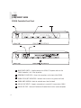
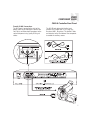

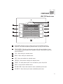

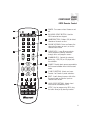


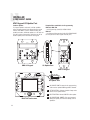
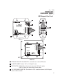
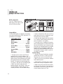
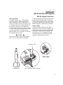
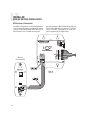


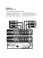
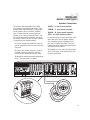

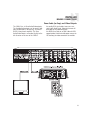
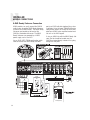
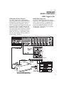
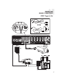
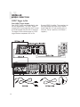
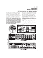
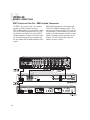
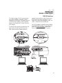
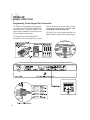
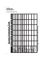
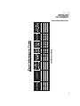
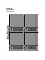
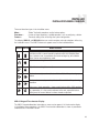


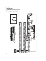
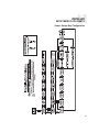
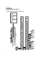

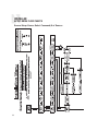
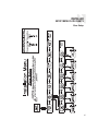
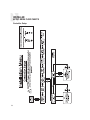
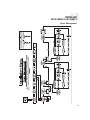
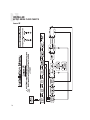
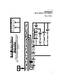
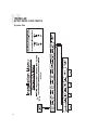
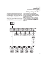
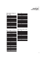
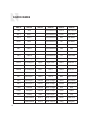
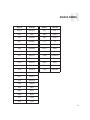
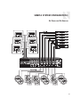
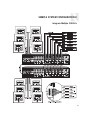

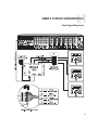
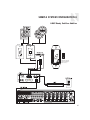

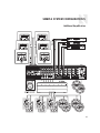


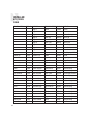
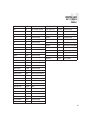
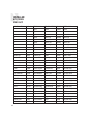


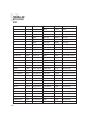
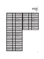
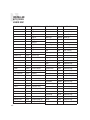

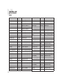
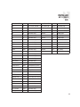
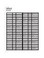

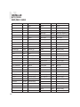
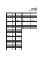
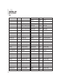
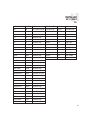
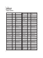
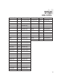
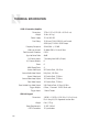


![Analyse de la tenue sismique des grands réservoirs[...]](http://vs1.manualzilla.com/store/data/006368585_1-4feb7f2835e3550c2e93b139d9c7a1e0-150x150.png)
![Analyse de la tenue sismique des grands réservoirs[...]](http://vs1.manualzilla.com/store/data/006357607_1-f6d301e5706d64d4958f6a452af28255-150x150.png)
