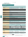
1
© Siemens AG 2008
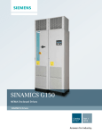
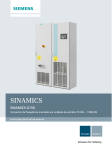
SINAMICS G150
Drive converter cabinet units
3/2
Overview
3/3
Benefits
3/3
Application
3/3
Design
3/5
3/5
3/6
3/6
Function
AOP30 Advanced Operator Panel
Communication with higher-level control and customer’s terminal block
Open-loop and closed-loop control
functions
Software and protection functions
3/8
3/9
3/11
3/11
3/12
3/13
3/16
Technical specifications
Derating data
Degrees of protection of cabinet units
Overload capacity
EMC guidelines
Single circuit
Parallel circuit
3/17
3/17
3/17
Selection and ordering data
Single circuit
Parallel circuit
3/18
3/20
3/21
3/22
Options
Option selection matrix
Ordering examples
Description of options
3/33
Line-side
power components
Line harmonics filters
Recommended fuses
3/6
3/33
3/35
3/37
Conductor cross-sections and
connections
Siemens D 11 · 2008
© Siemens AG 2008
SINAMICS G150
Drive converter cabinet units
SINAMICS G150 cabinet units
Overview
There are two versions of the drive converter cabinet units:
7 Vers io n A
All available line connection components, such as the main
switch, circuit-breakers, line contactor, line fuses, line filter, motor-side components, and additional monitoring devices, can
be installed as required. This version is also available with
power units connected in parallel.
7 Vers io n C
This offers an extremely space-optimized structure without
line-side components. This particularly slimline version can be
used, for example, when line connection components are accommodated in a central low-voltage distribution panel (MCC)
on the plantside.
The SINAMICS G150 drive converter cabinet units are available
for the following voltages and power ranges:
Line voltage
3
Power range for
single circuit
(versions A and C)
Power range for
parallel circuit
(version A)
380 ... 480 V 3 AC
110 ... 560 kW
630 ... 900 kW
500 ... 600 V 3 AC
110 ... 560 kW
630 ... 1000 kW
660 ... 690 V 3 AC
75 ... 800 kW
1000 ... 1500 kW
Degrees of protection are IP20 (standard), and, as an option,
IP21, IP23, IP43 and IP54.
Global use
SINAMICS G150 drive converter cabinet units are manufactured
in compliance with relevant international standards and regulations, and are therefore suitable for global use (# Technical
specifications).
SINAMICS G150 drive converter cabinet units, versions A and C
With its SINAMICS G150 drive converter cabinet units, Siemens
is offering a drive system on which all line-side and motor-side
components as well as the Power Module are integrated extremely compactly into a specially designed cabinet enclosure.
This approach minimizes the effort and expense required to configure and install them.
SINAMICS G150 has been specially tuned to the requirements
of drives with quadratic and constant load characteristics, with
medium performance requirements and without regenerative
feedback.
The control accuracy of the sensorless Vector Control is suitable
for most applications, and additional actual speed value encoders are therefore superfluous.
However, the SINAMICS G150 converters are optionally available with an encoder evaluator in order to handle applications
that require an encoder for plant-specific reasons.
SINAMICS G150 drive converter cabinet units offer an economic
drive solution that can be matched to customers’ specific requirements by adding from the wide range of available components and options.
3/2
Siemens D 11 · 2008
© Siemens AG 2008
SINAMICS G150
Drive converter cabinet units
75 kW to 1500 kW
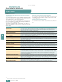
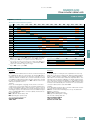
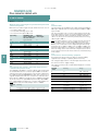
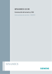
Benefits
1
2
3
4
5
6
7
3
G_D011_EN_00161
• Particularly quiet and compact converters due to the use of
state-of-the-art IGBT power semiconductors and an innovative cooling concept.
• Individual modules and power components can be replaced
quickly and easily, which ensures a higher level of plant availability. The design of replaceable components is based on the
principle that they must be quick and easy to change. In addition, the "SparesOnWeb" Internet tool makes it easy to view
the spare parts that are available for the system components
ordered.
• Can be easily integrated in automation solutions due to a communications interface supplied as standard and various analog and digital interfaces.
• Easy commissioning and parameterization using interactive
menus on the user-friendly AOP30 Advanced Operator Panel
with graphical LCD and plain-text display, or from a PC using
the STARTER commissioning tool (# Tools and configuration)
• Preset software functions make it easier to tailor the converter
to the individual plant. For example, the key functions for controlling pumps are stored as a preprogrammed macro in the
drive.
• They have been designed as "zoned" units and therefore offer
the highest possible standard of operational reliability. EMC
measures have been rigorously implemented. With the help of
simulated conditions, partitions have been designed to act as
air guides and heat dissipation units.
• Special measures used in the construction of the cabinets ensure that they remain mechanically durable throughout their
entire life cycle. All components, from individual parts to the
ready-to-connect cabinet, undergo rigorous testing throughout the entire production process. This guarantees a high level
of functional reliability during installation and commissioning,
as well as in operation.
1
Line reactor (< 500 kW standard)
2 PROFIBUS connection
Application
3 Line contactor
Variable-speed drives are advantageous for all applications that
involve moving, conveying, pumping or compressing solids,
liquids or gases.
5 Customer‘s terminal block
This means the following applications in particular:
• Pumps and fans
• Compressors
• Extruders and mixers
• Mills
4 Main control switch with fuses
6 Motor connection
7 Line connection
Standard version
Options
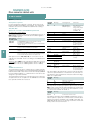
Design
SINAMICS G150 drive converter cabinet units are characterized
by their compact, modular, and service-friendly design.
A wide range of options is available depending on the cabinet
version which permit optimum adaptation of the drive system to
the respective requirements (# Options).
Example of design of a SINAMICS G150 drive converter cabinet unit,
version A
Siemens D 11 · 2008
3/3
© Siemens AG 2008
SINAMICS G150
Drive converter cabinet units
75 kW to 1500 kW
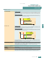
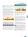
Design (continued)
Line connection
-X1
-X1
-X1
PE
PE
PE
Line connection
Main control switch 1
Main control switch 1)
Fuses 1)
Fuses 1)
Line contactor 1)
Line contactor 1)
Line reactor = 2 % Vk
Line reactor = 2 % Vk
< 500 kW as standard
≥500 kW only as
option L23!
AC
AC
AC
Rectifier
DC
DC
Rectifier
DC
DC link
DC link
DC
DC
DC
Converter
-X2
3
PE
G_D011_EN_00016c
Motor connection
Converter version A
Motor connection
Options
1) With an output current > 800 A,
the main control switch, fuses and line contactor are
replaced by a circuit-breaker.
Basic design of a SINAMICS G150 drive converter cabinet unit with a
number of version-specific options
Siemens D 11 · 2008
-X2
-X2
PE
PE
Converter version A
Options
Converter version C
3/4
AC
AC
AC
M
3~
> 1500 A, the main control switch, fuses and
1) With an output current _
line contactor are replaced by circuit-breakers. The output current
is composed of the sum of both subsystems.
Basic design of a SINAMICS G150 drive converter cabinet unit with
parallel circuit in order to increase output, with a number of versionspecific options
G_D011_EN_00066a
Converter
© Siemens AG 2 0 0 8
SINAMICS G150
Drive converter cabinet units
75 kW to 1500 kW
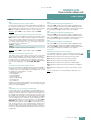
Function
Motor data
Back
p0304 MOT.U_rated
p0305 MOT. I_rated
p0307 MOT.P_rated
p0308 MOT.CosPhi_ rated
400.0 V
405.0 A
235.0 kW
0.870
Help
Change
OK
G_D011_en_00048
This information can be found on the motor rating plate and is
entered into the screens on the display by following a short,
menu-driven procedure. The cooling method of the motor must
be entered in addition.
AOP30 Advanced Operator Panel
Basic commissioning
Back
p0700 Pre-assignment BI
p1000 Default DI n_set
p1080 Minimum speed
p1082 Maximum speed
S/G150
TM 31
0.000
1500.000
Help
The user is guided through the screens for commissioning the
drive by the menu-driven display. Only 6 motor parameters
(which can be found on the motor rating plate) have to be entered when the AOP30 is commissioned for the first time. The
control is then optimized automatically to fine-tune the converter
to the motor.
English, French, German, Italian, Spanish and Chinese are
stored on the CU320 Control Unit’s CompactFlash card as operator panel languages. The desired language must be downloaded to the AOP30 prior to commissioning. Russian, Polish
and Czech are available in addition to these standard panel languages. These can be downloaded free of charge from the Internet under the following link:
http://support.automation.siemens.com/
The following pictures show examples of plain-text displays in
various operating phases.
Further
During operation, current data are output on the display as absolute values such as setpoint and actual values , or it is possible
to parameterize up to 3 process variables as a quasi-analog bar
display.
Operation
NSET 1465.50
Fout
48.50
Imot
748 A
0%
Nact
1465 rpm 0%
Nact
Vout
Imot
rpm
Hz
Nm
kW
rpm
Hz
12:25:30
1450.0 rpm
385.3 V
748
G_D011_EN_00011b
Operation
Nset
1450.00
48.50
Fout
2700
M
410
P act
Nact:
1450.0 rpm
12:25:30
410
kW
385.3 V
Pact
Vout
50
100%
50
100%
Any alarms which occur are signaled by flashing of the yellow
"ALARM" LED, faults by lighting up of the red "FAULT" LED.
There is also an indication of the cause displayed in plain text on
the display’s status line.
(3 : Vector) Current fault in
F 07901 Motor overspeed
First commissioning is carried out using the operator panel.
Help
Help
Back
Select.
Only 6 motor parameters have to be entered:
Alt
Back
Ack.
Motor overspeed
Fault val = 000000007 00000007 (hex)
Cause:
The maximum permisible positive or
negative speed has been exceeded.
The maximum permissile positive speed
is calculated as follows:
Back
G_D011_en_00051
Device commissioning
AOP settings
AOP diagnosis
G_D011_en_00047
Service /Commissioning
Drive commissioning
G_D011_EN_00012b
The AOP30’s two-stage safety concept prevents unintentional or
unauthorized changes to settings. Operation of the drive from
the operator panel can be disabled by a password ensuring that
only parameter values and process variables can be displayed
on the panel. The OFF key is factory-set to active but can also
be deactivated by the customer. A password can be used to prevent the unauthorized modification of converter parameters.
Change
power, speed, current, cos phi, voltage and frequency of the
motor.
Siemens D 11 · 2008
G_D011_en_00050
An AOP30 Advanced Operator Panel is located in the cabinet
door of the converter for operation, monitoring and commissioning tasks.
TM 32
AIO
rpm -1
rpm -1
G_D011_en_00049
The next screen contains the parameter values that are used to
automatically optimize the control.
3/5
3
© Siemens AG 2008
SINAMICS G150
Drive converter cabinet units
75 kW to 1500 kW
F u nc tion (continued)
Com m u nication w ith hig her-level control and cu stom er’s
term inal b lock
A communications interface on the CU 3 20 Control U nit and the
TM 3 1 Terminal M odule and TB 3 0 Terminal B oard are provided
as standard for use as the customer interface.
Y ou can use this customer’s terminal block to connect the sy stem to the higher-level controller using analog and digital signals, or to connect additional units.
O p en-loop and closed -loop control fu nctions
The converter control contains a high-quality sensorless Vector
Control w ith speed and current controls as w ell as motor and
converter protection.
S oftw are and p rotection fu nctions
The softw are functions available as standard are described below :
To simplify configuration and commissioning of the drive, the
TM 3 1 Terminal M odule can be preset to a variety of factory default settings.
S oftw are and p rotec tion fu nc tions
3
S etp oint inp u t
The setpoint can be defined internally and ex ternally , internally as fix ed or motoriz ed potentiometer or jog
setpoints, ex ternally via the communications interface or an analog input on the customer’s terminal
block . The internal fix ed setpoint and the motoriz ed potentiometer setpoint can be sw itched over or
adjusted using control commands via all interfaces.
M otor id entific ation
Automatic motor identification permits fast and simple commissioning and optimiz ation of the drive control.
R am p -fu nc tion g enerator
A user-friendly ramp-function generator w ith separately adjustable ramp-up and ramp-dow n times,
together w ith adjustable rounding times in the low er and upper speed ranges, improves the control
response and therefore prevents mechanical overloading of the drive train. The ramp-dow n ramps can
be parameteriz ed separately for emergency stop.
Vd c
The Vdc max controller automatically prevents overvoltages in the DC link if the set ramp-dow n ramp is too
short, for ex ample. This may also ex tend the set ramp-dow n time.
m ax
c ontroller
Kinetic b u ffering (KIP)
Line voltage failures are bridged to the ex tent permitted by the k inetic energy of the drive train. The
speed drops depending on the moment of inertia and load torque. The current speed setpoint is resumed
w hen the line voltage returns.
A u tom atic res tart 1)
The automatic restart sw itches the drive on again w hen the pow er is restored after a pow er failure, and
ramps up to the current speed setpoint.
F ly ing res tart 1)
The fly ing restart permits bumpless connection of the converter to a rotating motor.
T ec hnolog y c ontroller
The "technology controller’s" function module allow s simple control functions to be implemented, e.g.
level control or volumetric flow control. The technology controller is designed as a P ID controller, w hereby
the differentiator can be sw itched to the control deviation channel or the actual value channel (factory setting). The P , I, and D components can be set separately .
F ree fu nc tion b loc ks
U sing the freely programmable function block s, it is easy to implement logic and arithmetic functions for
controlling the SINAM ICS G150 unit. The block s can be programmed by means of an operator panel or
the STAR TE R commissioning tool.
Drive Control Chart (DCC)
Drive Control Chart (DCC) is an additional tool for the easy configuration of process-oriented functions for
the SINAM ICS G150. The block library contains a large selection of control, arithmetic and logic block s
as w ell as ex tensive open-loop and closed-loop control functions. The user-friendly DCC editor enables
easy graphical configuration and a clear representation of control loop structures as w ell as a high
degree of reusability of ex isting diagrams. DCC is an add-on to the STAR TE R commissioning tool
(# Tools and configuration).
I²t d etec tion for m otor p rotec tion
The motor temperature is calculated in a motor model stored in the converter softw are, tak ing into
account the current speed and load. M ore ex act sensing of the temperature, also tak ing into account the
influence of the ambient temperature, is possible by means of direct temperature sensing using K TY 84
sensors in the motor w inding.
E valu ation of m otor tem p eratu re
M otor protection by evaluating a K TY 84 or P TC temperature sensor. W hen a K TY 84 sensor is connected,
the limit values can be set for alarm or shutdow n. W hen connecting a P TC thermistor, the reaction follow ing triggering of it (alarm or shutdow n) can be defined.
M otor b loc king p rotec tion
A block ed motor is recogniz ed and protected against thermal overloading by shutting dow n.
1)
F actory setting: not activated (can be parameteriz ed)
3/6
Siemens D 11 · 2008
© Siemens AG 2008
SINAMICS G150
Drive converter cabinet units
75 kW to 1500 kW
Function (continued)
Safety Integrated
Safe Torq ue O ff (STO )
Description of functions
This function prevents the drive from restarting unexpectedly in accordance with EN 6 0204-1, Section 5.4.
Safe Torque O ff disables the drive pulses and disconnects the power supply to the motor (corresponds to
Stop Category 0 of EN 6 0204-1). The drive is reliably torque-free. This state is monitored internally in the
drive.
Application, customer benefits
STO has the immediate effect that the drive cannot supply any torque-generating energy. STO can be
used wherever the drive will reach a standstill in a sufficiently short time based on the load or when coasting down of the drive will not have any relevance for safety.
STO
G_D211_XX_00210
v
t
3
Safe Stop 1 (SS1)
Description of functions
The Safe Stop 1 function can safely stop the drive in accordance with EN 6 0204-1, Stop Category 1. When
the SS1 function is selected, the drive brakes along a quick stop ramp (O FF3) and automatically activates
the Safe Torque O ff when the parameterized safety delay timer runs down.
Application, customer benefits
When the stop function is activated and it does not come to a halt quickly enough due to the load inertia,
it can be actively braked by the converter. This integrated quick braking function eliminates the need for
costly mechanical brakes that are subject to wear.
STO
G_D211_XX_00205
v
∆t
t
The Safety Integrated functions STO and SS1 of SINAMICS G150 are certified by independent institutes.
The appropriate external test certificates and manufacturer declarations are available from the Siemens
representatives, as well as at
http://support.automation.siemens.com/WW/view/en/23158850
Terminal module for controlling functions STO and SS1 (option K8 2 )
The integrated safety functions, starting from the Safety Integrated (SI) input terminals of the SINAMICS
components (Control Unit, Power Module), satisfy the requirements specified in the Machinery Directive
9 8/37 /EC, EN 6 0204-1, DIN EN ISO 13849 -1 Category 3 (formerly EN 9 54-1) for Performance Level (PL) d
and IEC 6 1508 SIL2. These are certified by the BGIA. In combination with option K82, the safety functions
comply with Machinery Directive 9 8/37 /EC, EN 6 0204-1 and DIN EN ISO 13849 -1 Category 3
(formerly EN 9 54-1) for Performance Level (PL) d.
Power unit protection
Ground fault monitoring on the
output side
A ground fault on the output side is detected by aggregate current monitoring and results in shutdown in
grounded networks.
Electronic short-circuit protection
on output side
A short-circuit (e.g. on the converter output terminals, in the motor cable or in the motor’s terminal box) is
detected on the output side and the converter switches off with a fault.
Thermal overload protection
A warning message is issued first when the overtemperature threshold responds. If the temperature rises
further, either a shutdown is carried out or an automatic influencing of the pulse frequency or output current takes place so that a reduction in the thermal load is achieved. After elimination of the cause of the
fault (e.g. improvement in the ventilation), the original operating values are automatically resumed.
Siemens D 11 · 2008
3/7
© Siemens AG 2008
SINAMICS G150
Drive converter cabinet units
75 kW to 1500 kW
Technical specifications
Electrical data
Single circuit
Line voltages and
power ranges
• 380 ... 480 V 3 AC, $10 % (-15 % < 1 min) 110 ... 560 kW
Parallel circuit
630 ... 900 kW
• 500 ... 600 V 3 AC, $10 % (-15 % < 1 min) 110 ... 560 kW
630 ... 1000 kW
• 660 ... 690 V 3 AC, $10 % (-15 % < 1 min) 75 ... 800 kW
1000 ... 1500 kW
Types of supplies
TN/TT systems or isolated systems (IT systems)
Line frequency
47 ... 63 H z
Output frequency
0 ... 300 H z
Power factor
3
- Fundamental mode
> 0.98
- Total
0.93 ... 0.96
Converter efficiency
> 98 %
Control method
Vector Control with and without sensor or V/f control
Fixed speeds
15 fixed speeds plus 1 minimum speed, parameterizable
(in the default setting, 3 fixed setpoints plus 1 minimum speed are selectable using terminal
block/PROFIBUS)
Skipped speed ranges
4, parameterizable
Setpoint resolution
0.001 rpm digital
12 bit analog
Braking operation
Optional via braking unit
Mechanical data
Degree of protection
IP20 (higher degrees of protection up to IP54 optional)
Protection class '
In accordance with EN 50178 Part 1 1)
Cooling method
Forced air cooling AF in accordance with EN 60146
Sound pressure level LpA (1 m)
" 72 dB at 50 H z line frequency
Shock protection
BGV A3
Cabinet system
Rittal TS 8, doors with double-barb lock, three-section base plates for cable entry
Paint finish
RAL 7035 (indoor requirements)
" 75 dB
Compliance with standards
Standards
EN 50178 1)
EN 60146-1, EN 61800-2, EN 61800-3, EN 60204-1, EN 60529 2)
CE marking
In accordance with EMC directive No. 2004/108/EC and low-voltage directive No. 2006/95/EC
EMC conformance
The SINAMICS G150 converter systems are not designed for connection to the public power network
("First environment"). EMC conformance is compliant with the EMC product standard for variable-speed
drives EN 61800-3, "Second environment" (industrial networks). The equipment can cause electromagnetic interference when it is connected to the public network. If supplementary measures are taken, (e.g.
line filters, # option L00), it can also be operated in the "First environment".
Ambient conditions
Storage
Transport
Operation
Ambient temperature
-25 ... +55 °C
-25 ... +70 °C
from -40 °C for 24 hours
0 ... +40 °C
up to +50 °C see derating data
Relative humidity 2)
(non-condensing)
5 ... 95 %
5 ... 95 %
at 40 °C
5 ... 95 %
Class 1K4 to EN 60721-3-1
Class 2K3 to EN 60721-3-2
Class 3K3 to EN 60721-3-3
Environmental class/harmful chemical
substances 2)
Class 1C2 to EN 60721-3-1
Class 2C2 to EN 60721-3-2
Class 3C2 to EN 60721-3-3
Organic/biological influences 2)
Class 1B1 to EN 60721-3-1
Class 2B1 to EN 60721-3-2
Class 3B1 to EN 60721-3-3
Installation altitude
Up to 2000 m above sea level without derating, > 2000 m see derating data
Strain resistance
Storage
Transport
Operation
- Deflection
1.5 mm at 5 ... 9 H z
3.1 mm at 5 ... 9 H z
0.075 mm at 10 ... 58 H z
- Acceleration
5 m/s2 at > 9 ... 200 H z
10 m/s2 at > 9 ... 200 H z
10 m/s2 at > 58 ... 200 H z
Class 1M2 to EN 60721-3-1
Class 2M2 to EN 60721-3-2
–
40 m/s2 at 22 ms
100 m/s2 at 11 ms
100 m/s2 at 11 ms
Class 1M2 to EN 60721-3-1
Class 2M2 to EN 60721-3-2
Class 3M4 to EN 60721-3-3
Vibratory load 2)
Shock load 2)
- Acceleration
Deviations from the defined classes are identified by underlining.
1)
The EN standard specified is the European edition of international
standard IEC 62103.
3/8
Siemens D 11 · 2008
2)
The EN standards specified are the European editions of the international IEC standards with the same designations.
© Siemens AG 2008
SINAMICS G150
Drive converter cabinet units
75 kW to 1500 kW
Technical specifications (continued)
Derating data
Compensation of current derating as a function of installation altitude/ambient temperature
If the SINAMICS G150 drive converter cabinet units are operated at an installation altitude > 2000 m above sea level,
factors relating to a reduction of the maximum permissible output current (derating) must be taken into account. These are
specified in the tables below. It must be ensured that the air flow
corresponds to the rate specified in the technical specifications
tables. The specified values already include a permitted correction between installation altitude and ambient temperature (incoming air temperature at the inlet to the drive converter cabinet
unit).
Installation altitude Current derating
above sea level
at an ambient temperature of
m
20 °C
25 °C
30 °C
35 °C
40 °C
0-2000
2001-2500
87.0 %
83.7 %
96.3 %
91.4 %
92.5 %
87.9 %
80.5 %
96.7 %
92.3 %
88.8 %
84.3 %
77.3 %
92.7 %
88.4 %
85.0 %
80.8 %
74.0 %
40 °C
45 °C
50 °C
95.0 %
87.5 %
80.0 %
96.3 %
91.4 %
84.2 %
77.0 %
96.2 %
92.5 %
87.9 %
81.0 %
74.1 %
96.7 %
92.3 %
88.8 %
84.3 %
77.7 %
71.1 %
92.7 %
88.4 %
85.0 %
80.8 %
74.7 %
68,0 %
3001-3500
3501-4000
50 °C
95.0 %
96.2 %
100 %
2501-3000
45 °C
97.8 %
3
Current derating depending on ambient temperature (inlet-air temperature) and installation altitude
for cabinet units with degree of protection IP20, IP21, IP23 and IP43
Installation altitude Current derating
above sea level
at an ambient temperature of
m
20 °C
25 °C
30 °C
35 °C
0-2000
2001-2500
100 %
2501-3000
3001-3500
3501-4000
97.8 %
Current derating depending on ambient temperature (inlet-air temperature) and installation altitude
for cabinet units with degree of protection IP54
Voltage derating as a function of installation altitude
In addition to current derating, voltage derating must be considered in accordance with the following table with installation
altitudes > 2000 m above sea level.
Installation
altitude above
sea level
Voltage derating
for a rated input voltage of
m
380 V
400 V
420 V
440 V
460 V
480 V
500 V
525 V
550 V
575 V
600 V
0-2000
660 V
690 V
100 %
2001-2250
96 %
98 %
94 %
98 %
94 %
90 %
2251-2500
2501-2750
100 %
2751-3000
3001-3250
95 %
91 %
88 %
97 %
93 %
89 %
85 %
96 %
100 %
98 %
94 %
94 %
90 %
91 %
88 %
98 %
89 %
85 %
98 %
94 %
85 %
82 %
3251-3500
98 %
93 %
89 %
85 %
82 %
3501-3750
95 %
91 %
87 %
83 %
79 %
98 %
95 %
91 %
–
–
92 %
87 %
83 %
80 %
76 %
95 %
91 %
87 %
–
–
3751-4000
96 %
Voltage derating depending on installation altitude
Siemens D 11 · 2008
3/9
© Siemens AG 2 0 0 8
SINAMICS G150
Drive converter cabinet units
75 kW to 1500 kW
Technical specifications (continued)
Current derating depending on pulse frequency
To reduce motor noise or to increase output frequency, the pulse
frequency can be increased relative to the factory setting. When
the pulse frequency is increased, the derating factor of the
Order No.
6SL3710-...
output current must be taken into account. This derating factor
must be applied to the currents specified in the technical specifications.
Power
[kW]
Output current
at 2 kHz [A]
Derating factor
at 4 kHz
380 ... 4 80 V 3 AC
1GE32-17A0
110
210
82 %
1GE 32-67A0
132
260
83 %
1GE 33-17A0
160
310
88 %
1GE 33-87A0
200
380
87 %
1GE 35-07A0
250
490
78 %
Derating factor of the output current depending on the pulse frequency for units with a rated pulse frequency of 2 kHz
O rd e r N o .
6S L 3710-...
Pow er
[k W ]
O u tp u t c u rre n t
a t 1.25 k H z [A]
D e ra tin g fa c to r
a t 2.5 k H z
1GE 36-17 A0
315
605
72 %
1GE 37-57 A0
400
745
72 %
1GE 38-47 A0
450
840
79 %
1GE 41-07 A0
560
985
87 %
2GE 41-1AA0
630
1120
72 %
2GE 41-4AA0
710
1380
72 %
2GE 41-6AA0
900
1560
79 %
1GF31-87 A0
110
175
87 %
1GF32-27 A0
132
215
87 %
1GF32-67 A0
160
260
88 %
1GF33-37 A0
200
330
82 %
1GF34-17 A0
250
410
82 %
1GF34-77 A0
315
465
87 %
1GF35-87 A0
400
575
85 %
1GF37-47 A0
500
735
79 %
1GF38-17 A0
560
810
72 %
2GF38-6AA0
630
860
87 %
2GF41-1AA0
710
1070
85 %
2GF41-4AA0
1000
1360
79 %
1GH 28-57 A0
75
85
89 %
1GH 31-07 A0
90
100
88 %
380 ... 480 V 3 A C
3
5 00 ... 6 00 V 3 A C
6 6 0 ... 6 9 0 V 3 A C
1GH 31-27 A0
110
120
88 %
1GH 31-57 A0
132
150
84 %
1GH 31-87 A0
160
175
87 %
1GH 32-27 A0
200
215
87 %
1GH 32-67 A0
250
260
88 %
1GH 33-37 A0
315
330
82 %
1GH 34-17 A0
400
410
82 %
1GH 34-77 A0
450
465
87 %
1GH 35-87 A0
560
575
85 %
1GH 37-47 A0
710
735
79 %
1GH 38-17 A0
800
810
72 %
2GH 41-1AA0
1000
1070
85 %
2GH 41-4AA0
1350
1360
79 %
2GH 41-5AA0
1500
1500
72 %
Derating factor of the output current depending on the pulse frequency for units with a rated pulse frequency of 1.25 kHz
3/10
Siemens D 11 · 2008
© Siemens AG 2008
SINAMICS G150
Drive converter cabinet units
75 kW to 1500 kW
T ech nical s pecifications (continued)
Degrees of protection of cabinet units
O verload capacity
Standard EN 60529 applies to the protection of electrical eq uipment by means of housings, covers or eq uivalent, and includes:
• Protection of persons against accidental contact with live or
moving parts within the housing and protection of the eq uipment against the ingress of solid foreign bodies (touch protection and protection against ingress of foreign bodies)
• Protection of the eq uipment against the ingress of water (water protection)
• Abbreviations for the internationally agreed degrees of protection.
SINAMIC S G150 drive converter cabinet units are eq uipped with
an overload reserve to deal with breakaway torq ues, for ex ample. If larger surge loads occur, this must be taken into account
when configuring. In drives with overload req uirements, the appropriate base load current must therefore be used as a basis
for the req uired load.
F irs t dig it
(tou ch protection and
protection ag ains t
ing r es s of s olid
ob jects )
IP20 (standard)
Protected against solid No water protection
objects, diameter
% 12.5 mm.
IP21 (option M21)
IP23 (option M23)
IP43 (option M43)
IP54 (option M54)
S econd dig it
(protection of th e
eq u ipm ent ag ains t th e
ing r es s of w ater )
Protected against solid Protected against vertiobjects, diameter
cally falling water drops
% 12.5 mm.
V ertically falling water
drops shall not have a
harmful effect.
Protected against solid Protected against
objects, diameter
spraying water
% 12.5 mm.
Water sprayed on both
sides of the vertical at
an angle of up to 60°
shall not have a harmful
effect.
Protected against solid Protected against
objects, diameter
spraying water
% 1 mm.
Water sprayed on both
sides of the vertical at
an angle of up to 60°
shall not have a harmful
effect.
Dust protected.
Ingress of dust is not
totally prevented, but
dust must not be
allowed to enter in such
q uantities that the functioning or safety of the
eq uipment is impaired.
Protected against
splashing water
Water splashing onto
the enclosure from any
direction shall not have
a harmful effect.
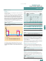
T he base load current IH for a high overload is based on a load
cycle of 150 % for 60 s or 160 % for 10 s.
Converter current
10 s
1.5 x IL
Short-time current 150 %
3
Short-time current 110 %
Rated current (continuous)
Base load current IL
for low overload
1.1 x IL
Irated
IL
G_D213_EN_00035
D eg r ees of
protection of th e
dr iv e conv er ter
cab inet u nit
T he base load current IL for a low overload is based on a load
cycle of 110 % for 60 s or 150 % for 10 s.
60 s
300 s
t
Low overload
Converter current
10 s
1.6 x IH
Short-time current 160 %
1.5 x IH
Short-time current 150 %
Rated current (continuous)
Base load current IH for high overload
Irated
IH
G_D213_EN_00036
T he degrees of protection are specified by abbreviations comprising the code letters IP and two digits.
T he criterion for overload is that the drive is operated with its
base load current before and after the overload occurs, and a
load duration of 300 s is assumed here.
60 s
300 s
t
High overload
Siemens D 11 · 2008
3/11
© Siemens AG 2008
SINAMICS G150
Drive converter cabinet units
75 kW to 1500 kW
Technical specifications (continued)
EMC guidelines
The electromagnetic compatibility describes - in accordance
with the definition of the EMC directive - the "capability of a device to work satisfactorily in the electromagnetic environment
without itself causing electromagnetic interferences which are
unacceptable for other devices present in this environment". To
guarantee that the appropriate EMC directives are observed, the
devices must demonstrate a sufficiently high noise immunity,
and also the emitted interference must be limited to acceptable
values.
The EMC requirements for "Variable-speed drive systems" are
described in the product standard EN 61800-3. A variablespeed drive system (or power drive system PDS) consists of the
drive converter and the electric motor including cables. The
driven machine is not part of the drive system. EN 61800-3 defines different limits depending on the location of the drive system, referred to as the first and second environments.
The first environment comprises living accomodation or locations where the drive system is directly connected to a public
low-voltage network without an intermediate transformer.
3
The second environment is understood to be all locations outside living areas. These are basically industrial areas which are
powered from the medium-voltage network via their own transformers.
The following graphic shows the assignment of the four categories to the first and second environment:
C1
First
environm ent
C2
Second
environm ent
C3
C4
G_D213_EN_00009
SINAMICS G150 drive converter cabinet units are almost exclusively used in the second environment (categories C3 and C4).
To limit emitted interference, the SINAMICS G150 drive converter cabinet units are equipped as standard with an R FI suppression filter in accordance with the limit values specified in
Category C3. This means that they meet the requirements for industrial use. Line filters (option L00) are available for use in the
first environment (Category C2).
Four different categories are defined in EN 61800-3 depending
on the location and the power of the drive:
SINAMICS G150 drive converter cabinet units fulfill the requirements for noise immunity defined in EN 61800-3 for the second
environment and consequently also the lower noise immunity
values in the first environment.
Category C1: Drive systems for rated voltages < 1000 V for unlimited use in the first environment.
The warning and installation information (part of the device
documentation) must be observed.
Category C2: Stationary drive systems for rated voltages
< 1000 V for use in the second environment. U se in the first environment is possible if the drive system is installed and used by
qualified personnel. The warning and installation information
supplied by the manufacturer must be observed.
Category C3: Drive systems for rated voltages < 1000 V for exclusive use in the second environment.
Category C4: Drive systems for rated voltages % 1000 V or for
rated currents % 400 A for use in complex systems in the second
environment.
3/12
Siemens D 11 · 2008
© Siemens AG 2008
SINAMICS G150
Drive converter cabinet units
75 kW to 1500 kW
Technical specifications (continued)
Tech nical specifications for single circuit
L ine voltage
380 ... 480 V 3 AC
Type rating
• with IL
at 50 Hz 400 V 1)
• with IH
at 50 Hz 400 V 1)
• with IL
at 60 Hz 460 V 2)
• with IH
at 60 Hz 460 V 2)
SIN AMICS G 150 drive converter cabinet units
6SL 3710-1G E
32-1...
32-6...
33-1...
33-8...
35-0...
36-1...
37-5...
38-4...
41-0...
kW
110
132
160
200
250
315
400
450
560
kW
90
110
132
160
200
250
315
400
450
hp
150
200
250
300
400
500
600
600
800
hp
125
150
200
250
350
350
450
500
700
210
205
178
260
250
233
310
302
277
380
370
340
490
477
438
605
590
460
745
725
570
840
820
700
985
960
860
O utput current
• Rated current Irated
A
• B ase load current IL 3) A
• B ase load current IH 4) A
Input current
• Rated input current 5)
• Input current, max.
• Current requirement
auxiliary supply
24 V DC 6)
A
A
A
229
335
1.1
284
410
1.1
338
495
1.35
395
606
1.35
509
781
1.35
629
967
1.4
775
1188
1.4
873
1344
1.4
1024
1573
1.5
P ower loss
kW
2.9
3.8
4.4
5.3
6.4
8.2
9.6
10.1
14.4
Cooling air requirement m3/s
0.17
0.23
0.36
0.36
0.36
0.78
0.78
0.78
1.48
Cable lengths
between converter
and motor 8)
• Shielded
• Unshielded
m
m
300
450
300
450
300
450
300
450
300
450
300
450
300
450
300
450
300
450
dB
67/68
69/73
69/73
69/73
69/73
70/73
70/73
70/73
72/75
mm
800/400
800/400
800/400
1000/400
1000/400
1200/600
1200/600
1200/600
1600/1000
mm
mm
2000
600
2000
600
2000
600
2000
600
2000
600
2000
600
2000
600
2000
600
2000
600
kg
320/225
320/225
390/300
480/300
480/300
860/670
865/670
1075/670
1360/980
Sound pressure
level LpA
(1 m) at 50/60 Hz
Dimensions
• Width for
version A/C
• Height 7)
• Depth
Weight
(without options) for
version A/C, approx.
3
Note: The type rating data in hp units are based on the NEC/CEC standards for the North American market.
1)
2)
3)
4)
5)
Rated output of a typ. 6-pole standard induction motor based on IL or
IH at 400 V 3 AC 50 Hz.
Rated output of a typ. 6-pole standard induction motor based on IL or
IH at 460 V 3 AC 60 Hz.
The base load current IL is based on a load cycle of 110 % for 60 s or
150 % for 10 s with a load cycle period of 300 s.
See technical specifications (# Overload capacity).
The base load current IH is based on a load cycle of 150 % for 60 s or
160 % for 10 s with a load cycle period of 300 s.
See technical specifications (# Overload capacity).
The current values given here are based on the rated output current.
6)
7)
8)
If the main power supply fails and drive control remains active, the
Power Module must be externally supplied with 24 V DC.
The following should also be taken into account:
– CU320:
0.8 A
– TM31:
0.5 A
– AOP30:
0.2 A
– SMC:
0.6 A
– Current requirement of digital inputs/outputs.
Version A: The cabinet height is increased by
250 mm for degree of protection IP21,
400 mm for degrees of protection IP23, IP43 and IP54,
405 mm for the M13 and M78 options.
Version C: The cabinet height is increased by
250 mm for degree of protection IP21,
400 mm for degrees of protection IP23, IP43 and IP54.
Longer cable lengths for specific configurations are available on
request.
Siemens D 11 · 2008
3/13
© Siemens AG 2008
SINAMICS G150
Drive converter cabinet units
75 kW to 1500 kW
Technical specifications (continued)
Line voltage
500 ... 600 V 3 AC
Type rating
• with IL
at 50 Hz 500 V 1)
• with IH
at 50 Hz 500 V 1)
• with IL
at 60 Hz 575 V 2)
• with IH
at 60 Hz 575 V 2)
SINAMICS G150 drive converter cabinet units
6SL3710-1GF
31-8...
32-2...
32-6...
33-3...
34-1...
34-7...
35-8...
37-4...
38-1...
kW
110
132
160
200
250
315
400
500
560
kW
90
110
132
160
200
250
315
450
500
hp
150
200
250
300
400
450
600
700
800
hp
150
200
200
250
350
450
500
700
700
175
171
157
215
208
192
260
250
233
330
320
280
410
400
367
465
452
416
575
560
514
735
710
657
810
790
724
270
410
1.35
343
525
1.4
426
655
1.4
483
740
1.4
598
918
1.4
764
1164
1.5
842
1295
1.5
Output current
A
• Rated current Irated
• Base load current IL 3) A
• Base load current IH 4) A
3
Input current
• Rated input current 5)
• Input current, max.
• Current requirement
auxiliary supply
24 V DC 6)
A
A
A
191
279
1.35
224
341
1.35
Power loss
kW
3.8
4.2
5.0
6.1
8.1
7.8
8.7
12.7
14.1
Cooling air requirement m3/s
0.36
0.36
0.36
0.36
0.78
0.78
0.78
1.48
1.48
Cable lengths
between converter and
motor 8)
• Shielded
m
• Unshielded
m
300
450
300
450
300
450
300
450
300
450
300
450
300
450
300
450
300
450
dB
69/73
69/73
69/73
69/73
72/75
72/75
72/75
72/75
72/75
mm
800/400
800/400
800/400
800/400
1200/600
1200/600
1200/600
1600/1000
1600/1000
mm
mm
2000
600
2000
600
2000
600
2000
600
2000
600
2000
600
2000
600
2000
600
2000
600
kg
390/300
390/300
390/300
390/300
860/670
860/670
860/670
1320/940
1360/980
Sound pressure
level LpA
(1 m) at 50/60 Hz
Dimensions
• Width for
version A/C
• Height 7)
• Depth
Weight
(without options) for
version A/C, approx.
Note: The type rating data in hp units are based on the NEC/CEC standards for the North American market.
1)
2)
3)
4)
5)
Rated output of a typ. 6-pole standard induction motor based on IL or
IH at 500 V 3 AC 50 Hz.
Rated output of a typ. 6-pole standard induction motor based on IL or
IH at 575 V 3 AC 60 Hz.
The base load current IL is based on a load cycle of 110 % for 60 s or
150 % for 10 s with a load cycle period of 300 s.
See technical specifications (# Overload capacity).
The base load current IH is based on a load cycle of 150 % for 60 s or
160 % for 10 s with a load cycle period of 300 s.
See technical specifications (# Overload capacity).
The current values given here are based on the rated output current.
6)
7)
8)
3/14
Siemens D 11 · 2008
If the main power supply fails and drive control remains active, the
Power Module must be externally supplied with 24 V DC.
The following should also be taken into account:
– CU320:
0.8 A
– TM31:
0.5 A
– AOP30:
0.2 A
– SMC:
0.6 A
– Current requirement of digital inputs/outputs.
Version A: The cabinet height is increased by
250 mm for degree of protection IP21,
400 mm for degrees of protection IP23, IP43 and IP54,
405 mm for the M13 and M78 options.
Version C: The cabinet height is increased by
250 mm for degree of protection IP21,
400 mm for degrees of protection IP23, IP43 and IP54.
Longer cable lengths for specific configurations are available on
request.
© Siemens AG 2008
SINAMICS G150
Drive converter cabinet units
75 kW to 1500 kW
Technical specifications (continued)
Line voltage
660 ... 690 V 3 AC
SINAMICS G150 drive converter cabinet units
6SL3710-1GH
28-5... 31-0... 31-2... 31-5... 31-8... 32-2...
32-6...
33-3...
34-1...
34-7...
35-8...
37-4...
38-1...
kW
75
90
110
132
160
200
250
315
400
450
560
710
800
kW
55
75
90
110
132
160
200
250
315
400
450
560
710
85
80
76
100
95
89
120
115
107
150
142
134
175
171
157
215
208
192
260
250
233
330
320
280
410
400
367
465
452
416
575
560
514
735
710
657
810
790
724
A
93
109
131
164
191
224
270
343
426
483
598
764
842
A
A
131
1.1
155
1.1
188
1.1
232
1.1
279
1.35
341
1.35
410
1.35
525
1.35
655
1.4
740
1.4
918
1.4
1164
1.5
1295
1.5
Power loss
kW
1.7
2.1
2.7
2.8
3.8
4.2
5.0
6.1
8.1
9.1
10.8
13.5
14.7
Cooling air requirement
m3/s
0.17
0.17
0.17
0.17
0.36
0.36
0.36
0.36
0.78
0.78
0.78
1.48
1.48
Type rating
• with IL
at 50 Hz 690 V 1)
• with IH
at 50 Hz 690 V 1)
Output current
• Rated current Irated
A
• Base load current IL 3) A
• Base load current IH 4) A
Input current
• Rated input
current 5)
• Input current, max.
• Current requirement
auxiliary supply
24 V DC 6)
Cable lengths
between converter
and motor 8)
• Shielded
• Unshielded
Sound pressure
level LpA
(1 m) at 50/60 Hz
Dimensions
• Width for
version A/C
• Height 7)
• Depth
Weight
(without options) for
version A/C, approx.
3
m
m
300
450
300
450
300
450
300
450
300
450
300
450
300
450
300
450
300
450
300
450
300
450
300
450
300
450
dB
67/68
67/68
67/68
67/68
67/73
67/73
67/73
67/73
72/75
72/75
72/75
72/75
72/75
mm
800/
400
2000
600
800/
400
2000
600
800/
400
2000
600
800/
400
2000
600
800/
400
2000
600
800/
400
2000
600
800/
400
2000
600
800/
400
2000
600
1200/
600
2000
600
1200/
600
2000
600
1200/
600
2000
600
1600/
1000
2000
600
1200/
1000
2000
600
320/
225
320/
225
320/
225
320/
225
390/
300
390/
300
390/
300
390/
300
860/
670
860/
670
860/
670
1320/
940
1360/
980
mm
mm
kg
Note: The type rating data in hp units are based on the NEC/CEC standards for the North American market.
1)
3)
4)
5)
Rated output of a typ. 6-pole standard induction motor based on IL or
IH at 690 V 3 AC 50 Hz.
The base load current IL is based on a load cycle of 110 % for 60 s or
150 % for 10 s with a load cycle period of 300 s.
See technical specifications (# Overload capacity).
The base load current IH is based on a load cycle of 150 % for 60 s or
160 % for 10 s with a load cycle period of 300 s.
See technical specifications (# Overload capacity).
The current values given here are based on the rated output current.
6)
7)
8)
If the main power supply fails and drive control remains active, the
Power Module must be externally supplied with 24 V DC.
The following should also be taken into account:
– CU320:
0.8 A
– TM31:
0.5 A
– AOP30:
0.2 A
– SMC:
0.6 A
– Current requirement of digital inputs/outputs.
Version A: The cabinet height is increased by
250 mm for degree of protection IP21,
400 mm for degrees of protection IP23, IP43 and IP54,
405 mm for the M13 and M78 options.
Version C: The cabinet height is increased by
250 mm for degree of protection IP21,
400 mm for degrees of protection IP23, IP43 and IP54.
Longer cable lengths for specific configurations are available on
request.
Siemens D 11 · 2008
3/15
© Siemens AG 2008
SINAMICS G150
Drive converter cabinet units
75 kW to 1500 kW
Technical specifications (continued)
Technical specifications for parallel circuit
Line voltage
Type rating
• with IL 1)
• with IH 1)
• with IL
at 60 Hz 460 V or 575 V 2)
• with IH
at 60 Hz 460 V or 575 V 2)
Output current
• Rated current Irated 8)
• Base load current IL 3) 8)
• Base load current IH 4) 8)
3
SINAMICS G150 drive converter cabinet units, version A
Type 6SL37102GE412GE412GE412GF382GF412GF411AA0
4AA0
6AA0
6AA0
1AA0
4AA0
2GH411AA0
380 ... 480 V 3 AC
660 ... 690 V 3 AC
500 ... 600 V 3 AC
2GH414AA0
2GH415AA0
kW
kW
hp
630
500
900
710
560
1000
900
710
1250
630
560
900
710
630
1000
1000
800
1250
1000
900
–
1350
1200
–
1500
1350
–
hp
700
900
1000
800
900
1000
–
–
–
A
A
A
1120
1092
850
1380
1340
1054
1560
1516
1294
860
836
770
1070
1036
950
1360
1314
1216
1070
1036
950
1360
1314
1216
1500
1462
1340
1174
1444
1624
904
1116
1424
1116
1424
1568
1800
2.8
2215
2.8
2495
3.0
1388
2.8
1708
2.8
2186
3.0
1708
2.8
2186
2.8
2406
3.0
Input current
• Rated input
A
current 5) 8)
• Input current, max.
• Current requirement auxil- A
iary supply 24 V DC 6)
Power loss
kW
16.2
19.0
19.9
15.4
17.2
23.8
21.3
26.6
29.0
Cooling air requirement
m3/s
1.56
1.56
1.56
1.56
1.56
2.96
1.56
2.96
2.96
Cable lengths
between converter and
motor 10)
• Shielded
• Unshielded
m
m
300
450
300
450
300
450
300
450
300
450
300
450
300
450
300
450
300
450
dB
73/76
73/76
73/76
75/78
75/78
75/78
75/78
75/78
75/78
mm
mm
mm
2400
2000
600
2400
2000
600
2400
2000
600
2400
2000
600
2400
2000
600
3200
2000
600
2400
2000
600
3200
2000
600
3200
2000
600
kg
1700
1710
2130
1700
1700
2620
1700
2620
2700
Sound pressure level LpA
(1 m) at 50/60 Hz
Dimensions
• Width 9)
• Height 7)
• Depth
Weight
(without options), approx.
Note: The type rating data in hp units are based on the NEC/CEC standards for the North American market.
Note:
In the case of converters with power units connected in parallel, units with a rated input current of
• <1500 A require option L13.
• % 1500 A require option L26.
(# Selection and ordering data)
1)
2)
3)
4)
5)
Rated output of a typ. 6-pole standard induction motor based on IL or
IH at 400 V, 500 V or 690 V 3 AC 50 Hz.
Rated output of a typ. 6-pole standard induction motor based on IL or
IH at 460 V or 575 V 3 AC 60 Hz.
The base load current IL is based on a load cycle of 110 % for 60 s or
150 % for 10 s with a load cycle period of 300 s.
See technical specifications (# Overload capacity).
The base load current IH is based on a load cycle of 150 % for 60 s or
160 % for 10 s with a load cycle period of 300 s.
See technical specifications (# Overload capacity).
The current values given here are based on the rated output current.
3/16
Siemens D 11 · 2008
6)
If the main power supply fails and drive control remains active, the
Power Module must be externally supplied with 24 V DC.
The following should also be taken into account:
– CU320: 0.8 A
– TM31: 0.5 A
– AOP30: 0.2 A
– SMC:
0.6 A
– Current requirement of digital inputs/outputs.
7) The cabinet height is increased by
250 mm for degree of protection IP21,
400 mm for degrees of protection IP23, IP43 and IP54,
405 mm for the M13 and M78 options.
8)
The currents listed here represent the aggregate current of both converter sections.
9) The power units connected in parallel are supplied as two transport
units.
10) Longer cable lengths for specific configurations are available on
request.
© Siemens AG 2008
SINAMICS G150
Drive converter cabinet units
75 kW to 1500 kW
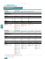
Selection and ordering data
Single circuit
Type rating
P arallel circuit
Rated output
current
at 400 V,
500 V or
690 V
at 60 Hz/
460 V or
575 V
kW
hp
A
SINAMICS G150
drive converter cabinet
units
Type rating
(Order No. supplement,
see below)
at 400 V,
500 V or
690 V
at 60 Hz/
460 V or
575 V
Order No.
kW
hp
380 ... 480 V 3 AC
Rated output
current
SINAMICS G150
drive converter
cabinet units,
Version A
A
Order No.
380 ... 480 V 3 AC
110
150
210
6SL3710-1GE32-17A0
630
900
1120
6SL3710-2GE41-1AA0
132
200
260
6SL3710-1GE32-67A0
710
1000
1380
6SL3710-2GE41-4AA0
160
250
310
6SL3710-1GE33-17A0
900
1250
1560
6SL3710-2GE41-6AA0
200
300
380
6SL3710-1GE33-87A0
500 ... 600 V 3 AC
250
400
490
6SL3710-1GE35-07A0
630
900
860
6SL3710-2GF38-6AA0
315
500
605
6SL3710-1GE36-17A0
710
1000
1070
6SL3710-2GF41-1AA0
400
600
745
6SL3710-1GE37-57A0
1000
1250
1360
6SL3710-2GF41-4AA0
450
700
840
6SL3710-1GE38-47A0
660 ... 690 V 3 AC
560
800
985
6SL3710-1GE41-07A0
1000
1070
6SL3710-2GH41-1AA0
1350
1360
6SL3710-2GH41-4AA0
1500
6SL3710-2GH41-5AA0
500 ... 600 V 3 AC
110
150
175
6SL3710-1GF31-87A0
1500
132
200
215
6SL3710-1GF32-27A0
160
250
260
6SL3710-1GF32-67A0
Note: The type rating data in hp units are based on the NEC/CEC
standards for the North American market.
200
300
330
6SL3710-1GF33-37A0
250
400
410
6SL3710-1GF34-17A0
315
450
465
6SL3710-1GF34-77A0
400
600
575
6SL3710-1GF35-87A0
500
700
735
6SL3710-1GF37-47A0
560
800
810
6SL3710-1GF38-17A0
75
85
6SL3710-1GH28-57A0
90
100
6SL3710-1GH31-07A0
110
120
6SL3710-1GH31-27A0
132
150
6SL3710-1GH31-57A0
380 ... 480 V 3 AC
160
175
6SL3710-1GH31-87A0
6SL3710-2GE41-1AA0
1174
L13 (line contactor)
200
215
6SL3710-1GH32-27A0
6SL3710-2GE41-4AA0
1444
L13 (line contactor)
250
260
6SL3710-1GH32-67A0
6SL3710-2GE41-6AA0
1624
L26 (circuit-breaker)
315
330
6SL3710-1GH33-37A0
500 ... 600 V 3 AC
400
410
6SL3710-1GH34-17A0
6SL3710-2GF38-6AA0
904
L13 (line contactor)
450
465
6SL3710-1GH34-77A0
6SL3710-2GF41-1AA0
1116
L13 (line contactor)
560
575
6SL3710-1GH35-87A0
6SL3710-2GF41-4AA0
1424
L13 (line contactor)
710
735
6SL3710-1GH37-47A0
660 ... 690 V 3 AC
800
810
6SL3710-1GH38-17A0
6SL3710-2GH41-1AA0
1116
L13 (line contactor)
Order No. supplement
6SL3710-2GH41-4AA0
1424
L13 (line contactor)
Version A
with possibility for mounting all connection components
A
6SL3710-2GH41-5AA0
1568
L26 (circuit-breaker)
Version C
Especially for space-saving mounting
C
660 ... 690 V 3 AC
In the case of converters with parallel-connected power units,
both converter sections must be simultaneously connected to
the supply network as the DC links of the two sections are coupled. For this reason, units with parallel circuit require the following components: Line contactors (option L13 for converters with
a rated input current of < 1500 A) or circuit-breakers (option L26
for converters with a rated input current of % 1500 A).
SINAMICS G150
drive converter cabinet
units,
Version A
Rated input
current
Order code (option)
A
Note: The type rating data in hp units are based on the NEC/CEC
standards for the North American market.
Siemens D 11 · 2008
3/17
3
© Siemens AG 2 0 0 8
SINAMICS G150
Drive converter cabinet units
75 kW to 1500 kW
Options
Note: When ordering a converter with options, add "-Z" to the
order number of the converter, followed by the order code(s) for
the desired option(s).
Example:
6SL3710-1GE32-1CA0-Z
+M07+D60+...
See also ordering examples.
Available options
Order
code
for version A
for version C
Line-side options
Line filter (RFI) for use in the first environment in accordance with EN 61800-3, L00
Category C2 (TN/TT systems)
–
Line contactor (for currents " 800 A with a single circuit or < 1 5 00 A
with a parallel circuit)
–
L13
D eliv ery without line reactor
L22
L ine reactor Vk = 2 %
L23
M ain control switch includ ing fuses resp. circuit-b reaker
L26
E M C shield b usb ar 1 )
M 70
P E (ground ) b usb ar 1 )
M 75
–
Lo a d -s id e o p tio n s
3
M otor reactor
L08
–
d v /d t filter plus V oltage P eak L imiter
L10
–
S ine-wav e filter (up to 2 5 0 kW at 3 80 ... 4 80 V , up to 1 3 2 kW at 5 00 ... 6 00 V )
L15
–
E M C shield b usb ar 1 )
M 70
P E (ground ) b usb ar 1 )
M 75
M o to r p ro te c tio n a n d s a fe ty fu n c tio n s
E M E R G E N CY O F F pushb utton, d oor mounted
E M E R G E N CY O F F Category 0, 2 3 0 V AC or 2 4 V D C
L45
–
L57
–
L59
–
L60
–
Thermistor motor protection unit with P TB approv al (alarm)
L83
–
Thermistor motor protection unit with P TB approv al (shutd own)
L84
–
P T1 00 ev aluation unit (for six P T1 00 sensors)
L86
–
Insulation monitoring
L87
–
Ad d itional touch protection
M 60
E M E R G E N CY S TO P Category 1 , 2 3 0 V AC
E M E R G E N CY S TO P Category 1 , 2 4 V D C
2)
2)
In c r e a s e in d e g r e e o f p ro te c tio n
IP 2 1 D egree of protection
M 21
IP 2 3 D egree of protection
M 23
IP 4 3 D egree of protection
M 43
IP 5 4 D egree of protection
M 54
M e c h a n ic a l o p tio n s
B ase 1 00 mm high, R AL 7 02 2
M 06
Cab le plinth 2 00 mm high, R AL 7 03 5
M 07
Top cab le entry , line sid e
M 13
–
Top cab le entry , motor sid e
M 78
–
Crane transport assemb ly (top-mounted )
M 90
possib le
–
1)
2)
not supported
This option is listed for the line-side and load-side options, but is only
required once.
The drive stop requirements must be taken into account with this
option. Additional braking units may be required.
The selection matrix must be observed w ith respect to the
combination of options.
3/18
Siemens D 11 · 2008
Conv erter v ersion A
Conv erter v ersion C
© Siemens AG 2008
SINAMICS G150
Drive converter cabinet units
75 kW to 1500 kW
Options (continued)
Available options
Order
code
for version A
for version C
Other options
CAN protocol CBC10 Communication Board
G 20
PROFINET CBE20 Communication Board
G 33
Additional TM31 customer terminal module
G 61
SMC30 Sensor Module Cabinet-Mounted
K 50
VSM10 Voltage Sensing Module Cabinet-Mounted
K 51
–
Terminal interface for "Safe Torq ue Off" and "Safe Stop 1" safety functions
K 82
–
Connection for external auxiliary eq uipment (controlled, max. 10 A)
L19
–
Cabinet light with service socket
L50
–
Cabinet anti-condensation heating
L55
–
Braking unit 25 kW (P20 power: 100 kW)
L61
–
Braking unit 50 kW (P20 power: 200 kW)
L62
–
Special cabinet paint finish 3)
Y 09
D ocumentation (standard: English/G erman)
Customer documentation (circuit diagram, terminal diagram, layout diagram) D 02
in DX F format
Customer documentation in paper format
3
D 04
Preliminary copy of customer documentation
D 14
Documentation language: English/French
D 58
Documentation language: English/Spanish
D 60
Documentation language: English/Italian
D 80
Languages (standard: English/G erman)
Rating plate language in English/French
T 58
Rating plate language in English/Spanish
T 60
Rating plate language in English/Italian
T 80
Options specific to the chemical industry
NAMUR terminal block
B00
–
Safely isolated 24 V power supply (PELV)
B02
–
Separate output for external auxiliaries (uncontrolled)
B03
–
Options specific to the shipbuilding industry
Marine version
M66
Individual certificate from Germanischer Lloyd (GL)
E11
Individual certificate from Lloyds Register (LR)
E21
Individual certificate from Bureau Veritas (BV)
E31
Individual certificate from Det Norske Veritas (DNV)
E51
Individual certificate from American Bureau of Shipping (ABS)
E61
Individual certificate from Chinese Classification Society (CCS)
E71
Converter acceptance inspection in presence of customer
Visual inspection
F 03
Function test of the converter without motor connected
F 71
Function test of the converter with test bay motor (no load)
F 75
Insulation test on converter
F 77
Customiz ed converter acceptance (on req uest)
F 97
possible
–
3)
not supported
The order code Y.. req uires data in plain text.
The selection matrix mu st b e ob served w ith resp ect to the
comb ination of op tions.
Converter version A
Converter version C
Siemens D 11 · 2008
3/19
© Siemens AG 2008
SINAMICS G150
Drive converter cabinet units
75 kW to 1500 kW
Options (continued)
Option selection matrix
Certain options are mutually exclusive. The following tables only
provide an overview. Please refer to the descriptions of the individual options for a precise description of options and other exclusions.
possible combination
combination not supported
–
E lectrical options
G20 G33 K50 K51 K82 L00 L13 L15 L19 L22 L23 L26 L45 L50 L55 L57 L59 L60 L61 L62 L83 L84 L86 L87
–
G20
G33
–
–
K50
K51
–
4)
K82
–
L00
3
1)
–
2)
L13
3)
3)
3)
3)
3)
3)
–
–
L15
L19
L22
–
L23
1)
–
–
2)
L26
L45
L50
L55
L57
3)
3)
L59
3)
3)
–
L60
3)
3)
–
–
–
–
L61
–
L62
L83
L84
L86
L87
1)
2)
4)
–
For converters < 500 kW/700 hp, the line reactor (order code L23) is
supplied with the converter as standard.
For converters % 500 kW/700 hp, option L23 must be ordered if
• the converters are to be operated on lines with short-circuit power
(RSC > 20) or
• a line filter is used (option L00).
Combination L13/L26 is only possible for currents of < 800 A.
Circuit-breakers are used from 800 A upwards. These perform the
same function as options L13 and L26.
3/20
Siemens D 11 · 2008
3)
4)
Converters in a single circuit require either option L13 or, for currents
of > 800 A option L26 (circuit-breaker).
Converters in a parallel circuit require L13 or L26.
Braking units may also be needed, depending on the drive stopping
time required.
K 82 and L87 can be combined as standard for converters with parallel-connected power units. This combination is available on request
for converters in a single circuit.
© Siemens AG 2008
SINAMICS G150
Drive converter cabinet units
75 kW to 1500 kW
Options (continued)
Mechanical options/electrical options
L00
L08
L10
L15
M06
M07
M13
M21
M23
M43
M54
M60
M66
M70
–
L08
L10
–
L15
–
M78
–
–
–
–
–
M90
–
–
M06
–
M07
–
M13
–
M21
–
–
M23
–
M43
–
–
M54
–
M60
M66
M70
M75
5)
L00
5)
–
7)
–
–
–
–
8)
–
–
–
–
–
7)
–
–
–
8)
6)
–
–
–
–
6)
5)
6)
M75
M78
6)
–
–
–
–
5)
–
–
5)
3
5)
M90
5)
6)
7)
8)
Option L00 includes option M70.
If the line connection (option M13) and the motor connection (option
M78) are from above, the EMC shield bus (option M70) and the PE
busbar (option M75) are not required in the lower cabinet area.
Can only be selected for converters in the voltage range 400 V up to
250 kW, 500 V up to 200 kW and 69 0 V up to 315 kW. Option M60 is
supplied as standard for larger power ranges.
Option M66 includes option M23.
Rating plate language
T58
T58
T60
–
T80
–
T60
T80
–
–
–
–
Ordering ex amples
Example 1
Example 2
Tas k :
A drive converter cabinet unit is needed to control the fan speed
for a 380 kW fan drive for connecting to an existing 400 V MCC
outgoing circuit. The rated speed of the fan is 9 75 rpm. As a result of the ambient conditions, the converter should be mounted
on a 100 mm cabinet base and the degree of protection should
be IP54. The installation altitude is < 1000 m above sea level, the
ambient temperature is 45 ° C.
Tas k :
A 280 kW pump to control pressure equalization is to be supplied via a converter for a brand new district heating pumping
station. A 69 0 V supply is available. The installation altitude is
350 m above sea level and the ambient temperature 40 ° C. The
rated speed of the pump is 740 rpm. The pump unit and motor
are located in an unmanned substation, so the winding temperature of the motor must be monitored by PT100 resistance thermometers and evaluated by the converter. The color of the drive
converter cabinet units is to be RAL 3002.
S o lu tio n :
Due to the existing MCC outgoing circuit, the line connection
components, such as main switch, line contactor and line fuses,
can be omitted and the space-saving version C can be selected.
For this constellation, taking into account the derating factors for
IP54 degree of protection and for the increased ambient temperature, a 450 kW, 400 V drive converter cabinet unit must be selected with options
M06 ( 100 mm cabinet base) and
M54 (IP54 degree of protection)
The relevant ordering data are:
6S L3710-1GE38-4CA0-Z
+ M06 + M54
S o lu tio n :
A 315 kW, 69 0 V version A drive converter cabinet unit must be
selected with the following options:
L26 Main control switch including fuses resp. circuit-breaker
L13 (line contactor),
L86 (PT100 evaluation unit) and
Y09 (special cabinet paint coating).
The relevant ordering data are:
6S L3710-1GH 33-3AA0-Z
+ L26 + L13 + L86 + Y09
Cabinet color R AL 3002
Siemens D 11 · 2008
3/21
© Siemens AG 2008
SINAMICS G150
Drive converter cabinet units
75 kW to 1500 kW
Options (continued)
Description of options
Terminal
-A1-X 2:
Meaning
Preassignment
Comments
10
DI
ON (dynamic)/
ON/OFF (static)
The effective mode
can be coded
using a wire jumper
on the terminal
-A1-400:9; 10.
Exclusion list to other options:
11
DI
OFF (dynamic)
The following limitations and exclusion resulting from the use of
B00 NAMUR terminal block must be observed with regard to
other available options.
12
DI
Faster
13
DI
Slower
14
DI
RESET
15
DI
Interlock
16
DI
Counterclockwise
"0" signal for CW
phase sequence
"1" signal for CCW
phase sequence
17, 18
Line
disconnection
EMERGENCY OFF
sequence
30, 31
Ready
Relay output
(NO contact)
32, 33
Motor rotates
Relay output
(NO contact)
Fault
Relay output
(changeover
contact)
For more detailed descriptions of options, please refer to the
Engineering Manual SINAMICS Low Voltage. The engineering
manual is stored on the CD-ROM included with the catalog.
B 00,B 02,B 03
Options in accordance with N A MU R req uirements
N ot permissi- Reason
ble w ith option
3
L45, L57,
L59, L60
An EMERGENCY OFF of Category 0 is already
included in the NAMUR version.
The forced line disconnection is accessed at terminals
-A1-X2: 17, 18.
L83, L84
Option B00 already provides a thermistor motor
protection unit (shutdown) as standard.
L19
A combination of options L19 and B00 is available on
request.
L87
The insulation monitor monitors the complete network
which is electrically connected. An insulation monitor
must therefore be provided on the plant side.
With options such as L50, L55, L86, the connection is as described in the standard. There is no wiring to the NAMUR terminal block.
Attention: Option B00 must be ordered with supply disconnection
option L13 for currents of < 800 A (parallel circuit: < 1500 A) or
option L26 for currents of > 800 A (parallel circuit: % 1500 A).
B 00
N A MU R terminal block
The terminal block has been configured in accordance with the
requirements and guidelines of the Standards Working Group for
Instrumentation and Control in the Chemicals Industry (NAMUR
Recommendation NE37), i.e. certain functions of the device are
assigned to specified terminals.
The terminal block and the associated functions are reduced to
a required amount. In comparison to the NAMUR recommendation, optional terminals are not listed.
34
DO (NO)
35
DO (COM)
36
DO (NC)
50, 51
AI
0/4-20 mA
Speed setpoint
60, 61
AO
0/4-20 mA
Motor frequency
62, 63
AO
0/4-20 mA
Motor current
Motor current is
default setting; can
be reparameterized
for other variables
The 24 V supply is provided at the customer end via terminals
-A1-X2:1-3 (fused inside the converter with 1 A). It must be ensured that the safety requirements "Protective extra-low voltage,
PELV" are complied with.
Terminal
-A1-X 2:
Meaning
1
M
2
P24
Reference conductor
Infeed 24 V DC
3
P24
Outgoing circuit 24 V DC
For temperature monitoring of explosion-proof motors, the option
B00 contains a PTC thermistor with PTB approval. A switch-off is
carried out if the limit is exceeded. The associated PTC sensor
is connected to terminal -A1-X3:90, 91.
Terminal
-A1-X 3:
Meaning
90, 91
AI
Connection of PTC sensor
In parallel to operation via the NAMUR terminal block, there is
also the option to operate the converter via the communications
interface provided as standard on the CU320 Control Unit. The
PROFIdrive profile "process technology" used in the chemical industry can be selected via macros.
3/22
Siemens D 11 · 2008
© Siemens AG 2008
SINAMICS G150
Drive converter cabinet units
75 kW to 1500 kW
Options (continued)
B02
S afely isolated 24 V power supply (P ELV )
D58
Documentation language: English/F rench
If no protective separation for 24 V supply (PELV) is available at
the customer end, this option is used to fit a second power supply to guarantee the PELV. (Terminal assignments as for option
B00, 24 V supply at terminals -A1-X1:1, 2, 3 are omitted.)
With option D58, the documentation will be supplied with the
converter in English and French (standard: English/German).
When option D04 is specified in addition, a printed version of the
documentation in English and French is also supplied.
Attention: Option B02 is only possible together with B00.
D60
Documentation language: English/S panish
B03
S eparate output for external auxiliaries (uncontrolled)
If a motor fan has to be supplied on the plant, for example, option
B03 provides an uncontrolled separate output with a 10 A fuse.
As soon as the supply voltage is present at the converter input,
a voltage is also present at these terminals. This corresponds to
the converter input voltage (V = Vline). This must be observed
when planning the external fans.
Terminal
-A1-X1:
Meaning
1, 2, 3, P E
Separate output for external auxiliaries
Attention: Option B03 is only possible together with B00.
D02
C ustomer documentation in DX F format
With option D60, the documentation will be supplied with the
converter in English and Spanish (standard: English/German).
When option D04 is specified in addition, a printed version of the
documentation in English and Spanish is also supplied.
D80
Documentation language: English/Italian
With option D80, the documentation will be supplied with the
converter in English and Italian (standard: English/German).
When option D04 is specified in addition, a printed version of the
documentation in English and Italian is also supplied.
E11 to E71
Individual certification of the converter
3
The individual certification of the converter by the relevant certification body contains the expansions described for option M66.
This option can be used to order documents such as circuit diagrams, terminal diagrams, arrangement diagram and dimensional drawings in DXF format, in order to process them further
in CAD systems, for example. They are supplied on the documentation CD in the desired language (standard is English/German, for other languages, see options D58, D60, D80).
E51 Individual certificate from Det Norske Veritas (DNV)
D04
C ustomer documentation in paper format
E61 Individual certificate from American Bureau of Shipping
(ABS)
Device documentation is supplied electronically on CD-ROM as
standard. If the customer also requires a hard copy of the documentation and selects option D04, the following documents will
be shipped in a folder with the converter:
• Operating instructions
• Circuit diagram
• Terminal diagram
• Layout diagram
• Dimensional drawing
• Spare parts list
• Test certificate
E71 Individual certificate from Chinese Classification Society
(CCS)
E11 Individual certificate from Germanischer Lloyd (GL)
E21 Individual certificate from Lloyds Register (LR)
E31 Individual certificate from Bureau Veritas (BV)
Note: A combination of several individual certificates is not
provided.
Regardless of whether option D04 is selected, a hard copy of the
safety and transportation guidelines, a check list and a registration form is always supplied.
D14
P reliminary copy of customer documentation
If documents such as circuit diagrams, terminal diagrams, arrangement diagrams and dimensional drawings are required in
advance for system engineering, advance documentation can
be ordered when ordering the converter. These documents are
then supplied electronically a few working days after the order
has been entered. The plant-specific documentation is supplied
to the ordering party via e-mail in the desired language (standard is English/German, for other languages, see options D58,
D60, D80). The recipient’s e-mail address must be provided
when the order is placed. If option D02 is selected at the same
time, the documents are sent out in DXF format, otherwise they
are sent in PDF format. In the e-mail, the recipient is also provided with a link for downloading general advance documentation such as Operating Instructions, Manuals and Commissioning Manuals.
Siemens D 11 · 2008
3/23
© Siemens AG 2008
SINAMICS G150
Drive converter cabinet units
75 kW to 1500 kW
Options (continued)
F03, F71, F75, F77, F97
Converter acceptance in the presence of the customer
Order
code
Description
F03
Visual
inspection
F71
3
F75
The scope of the acceptance comprises:
• Checking the degree of protection
• Checking the equipment (components)
• Checking the equipment identifier
• Checking the clearance and creepage
distances
• Checking the cables
• Checking the customer documentation
• Submitting the acceptance report
The checks are carried out with the converter
deenergized.
Function test The scope of the acceptance comprises:
of the con• Visual inspection as described for option
verter without
F03
motor con• Checking the power supply
nected
• Checking the protection and monitoring
equipment (simulation)
• Checking the fans
• Testing the precharging
• Function test without connected motor
• Submitting the acceptance report
Following the visual inspection in the deenergized state, the converter is connected to the
rated voltage. No current flows at the converter output.
Function test The scope of the acceptance comprises:
of the con• Visual inspection as described for option
verter with
F03
test bay motor
• Checking the power supply
(no load)
• Checking the protection and monitoring
equipment (simulation)
• Checking the fans
• Testing the precharging
• Function test with test bay motor (no load)
• Submitting the acceptance report
Following the visual inspection in the deenergized state, the converter is connected to the
rated voltage.
A small current flows at the converter’s output
in order to operate the test bay motor (no
load).
F77
Insulation test The scope of the acceptance comprises:
on converter • H igh-voltage test
• Measurement of insulation resistance
F97
Customized
acceptance
(on request)
If acceptances are desired which are not covered by the options F03, F71, F75 or F77,
customized acceptances/supplementary
tests can be ordered using the order code
F97 on request and following technical
clarification.
G 20
CBC10 Communication Board
The CBC10 Communication Board is used to interface the
CU320 Control Unit and thus the SINAMICS G150 to the CAN
(Controller Area Network) protocol. The board’s driver software
fulfills the standards of the following CANopen specification of
the CiA organization (CAN in Automation):
• Communication profiles in accordance with DS 301
• Drive profile in accordance with DSP 402
(in this case Profile Velocity Mode)
• EDS (Electronic Data Sheet)
in accordance with DSP 306
• Operating status signaling in accordance with DSP 305
The CBC10 Communication Board plugs into the option slot on
the CU320 Control Unit. The CAN interface on the CBC10 has
2 SUB-D connections for input and output.
G 33
CBE20 Communication Board
The CBE20 Communication Board can be used to connect the
SINAMICS G150 to a PROFINET IO network via a
CU320 Control Unit.
The SINAMICS G150 then assumes the function of a PROFINET
IO device and can perform the following functions:
• PROFINET IO device
• 100 Mbit/s full-duplex
• Supports real-time classes of PROFINET IO:
- RT (Real-Time)
- IRT (Isochronous Real-Time), minimum send cycle 500 )s
• Connects to controls as a PROFINET IO device using
PROFIdrive compliant with Specification V4
• Standard TCP/IP communication for engineering processes
using the STARTER commissioning tool
• Integrated 4-port switch with four RJ 45 B sockets based on
the PROFINET AXIC ERTEC400. The optimum topology (line,
star, tree) can therefore be configured without additional external switches.
The CBE20 Communication Board plugs into the option slot on
the CU320 Control Unit.
G 61
Additional TM31 customer terminal module
The standard version of the SINAMICS G150 drive converter
cabinet units already contains an Interface Module (TM31 Terminal Module). With a second module, the number of available digital inputs/outputs and the number of analog inputs/outputs
within the drive system can be expanded.
K 50
SMC30 Sensor Module Cabinet-Mounted
The SMC30 Sensor Module can be used to acquire the actual
motor speed. The signals emitted by the rotary pulse encoder
are converted here and made available via the DRIVE-CLiQ interface of the closed-loop control for evaluation purposes.
The following encoders are supported by the SMC30:
• TTL encoders
• H TL encoders.
The motor temperature can also be detected using KTY84-130
or PTC thermistors.
3/24
Siemens D 11 · 2008
© Siemens AG 2008
SINAMICS G150
Drive converter cabinet units
75 kW to 1500 kW
Options (continued)
K51
VSM10 Voltage Sensing Module Cabinet-Mounted
A motor reactor can be supplied on request for drive converter
cabinet units with power units connected in parallel.
The VSM10 Voltage Sensing Module reads the voltage waveshape at the motor end. This allows the SINAMICS G150 converter to be connected to a permanent-field, encoderless synchronous machine (flying restart function). The VSM10 is wired
to the motor terminals in a short-circuit-proof connection in the
delivery state.
Option L08 is only available with version A and cannot be combined with option M78 (top cable entry, motor side).
K82
Terminal interface for "Safe Torque Off" and
"Safe STOP 1" safety functions
The terminal module provides control of the safety functions integrated in the devices in a variable wide voltage range from
24 V to 240 V DC/AC and can, therefore, be adapted to the relevant plant conditions.
The integrated safety functions, starting from the Safety Integrated (SI) input terminals of the SINAMICS components
(Control Unit, Power Module), satisfy the requirements
specified in the Machinery Directive 98/37/EC, EN 60204-1,
DIN EN ISO 13849-1 Category 3 (formerly EN 954-1) for Performance Level (PL) d and IEC 61508 SIL2. These are certified by
the BGIA.
In combination with option K82, the safety functions comply
with Machinery Directive 98/37/EC, EN 60204-1 and
DIN EN ISO 13849-1 Category 3 (formerly EN 954-1) for Performance Level (PL) d. Use option K82 to activate the following
Safety Integrated functions (terminology according to
draft IEC 61800-5-2):
• Safe Torque Off (STO)
• Safe Stop 1 (SS1) (time-controlled)
L00
Line filter (RFI) for use in the first environment in accordance
with EN 61800-3, Category C2 (TN/TT systems)
To limit the emitted interference, the drive converters are
equipped as standard with a radio interference suppression
filter that conforms to the limits defined in Category C3.
SINAMICS G150 converters equipped with the line filter also
meet the limits for use in the first environment (Category C2) as
specified in EN 61800-3.
The SINAMICS G150 units comply as standard with the immunity requirements defined in EN 61800-3 for the first and second
environments.
In conjunction with line reactors, line filters also limit the conducted interference emitted by the Power Modules to the limit
values of Category C2 defined in product standard EN 61800-3.
Option L23 must be ordered in addition for converter outputs
> 500 kW.
To allow the power cable shield to be connected in conformance
with EMC requirements, an additional EMC shield bus (option
M70) is factory fitted at the converter input and output. A separate order is not required in this case.
L08
Motor reactor
Motor reactors reduce the voltage load on the motor windings by
reducing the voltage gradients on the motor terminals generated
when the converter is used. At the same time, the capacitive
charge/discharge currents that occur at the converter output
when long motor cables are used are reduced. The maximum
permissible output frequency when a motor reactor is used is
150 Hz.
L10
dv/dt filter plus Voltage Peak Limiter
The dv/dt filter plus VPL consists of two components: the dv/dt
reactor and the VPL (Voltage Peak Limiter), which limits voltage
peaks and returns the energy to the DC link.
The dv/dt filters plus VPL are to be used for motors of the series
only if the insulation system is unknown or insufficient. Standard
motors if the 1LA5, 1LA6 and 1LA8 series only require them in
cases where the motor has not been specially insulated for
operation on a converter (see Catalog D 81.1, chapter "Motors
operating with frequency converters").
The dv/dt filters plus VPL limit the rate of voltage rise to values of
< 500 V/)s and the typical voltage peaks at rated line voltages
to the following values (with motor cable lengths of < 150 m):
< 1000 V at Vline < 575 V
3
< 1250 V at 660 V < Vline < 690 V.
Depending on the converter output, option L10 can be accommodated in the drive converter cabinet unit or an additional cabinet of width 400 mm is required.
Voltage
range
Installation of
the dv/dt filter plus VPL
within the drive converter
cabinet unit
Installation of the VPL
in an additional cabinet
V
kW
kW
380 ... 480
110 ... 250
315 ... 560
500 ... 600
110 ... 200
250 ... 560
660 ... 690
75 ... 315
400 ... 800
The dv/dt filter plus VPL is available on request for drive converter cabinet units with power units connected in parallel.
Option L10 cannot be combined with option M78 (top cable
entry, motor side).
Max. connectable motor cable lengths
Maximum cable lengths
Protoflex EMC 3 Plus 1) Shielded
cable, e.g.
Protodur NYCWY
Unshielded
cable, e.g.
Protodur NYY
m
m
m
300
450
Without reactor or filter
300
With motor reactor (option L08)
300
300
450
With dv/dt filter plus VPL (option L10)
300
300
450
Longer cable lengths for specific configurations are available on
request.
1)
Protoflex EMC 3 Plus cables comply with the limits for interference
voltage and emitted noise specified in standard EN 61800-3 for use in
the second environment. The limits in standard EN 61800-3 correspond to those in standard EN 55011 Class A Group 2.
Siemens D 11 · 2008
3/25
© Siemens AG 2008
SINAMICS G150
Drive converter cabinet units
75 kW to 1500 kW
Options (continued)
Minimum motor cable lengths for operation with power units
connected in parallel
L15
Sine-wave filter
Minimum motor cable lengths must be adhered to in the case of
• a 12-pulse supply and
• a motor with a winding system and
• no motor reactor (option L08) used.
Sine-wave filters are available in the voltage range from 380 V to
480 V up to 250 kW and in the voltage range from 500 V to 600 V
up to 132 kW.
Type rating
SINAMICS G150
Minimum
drive converter cabi- cable length
net unit, version A
kW
Type 6SL3710-...
m
630
-2GE41-1AA0
13
710
-2GE41-4AA0
10
900
-2GE41-6AA0
9
380 ... 480 V 3 AC
500 ... 600 V 3 AC
3
The sine-wave filter at the converter output delivers practically
sinusoidal voltages on the motor so that standard motors can be
used without special cables and without derating. Standard
cables can be used. The maximum permitted motor incoming
cable length is 300 m.
Note: The pulse frequency of the converter must be increased
when used in conjunction with option L15. This reduces the
power available at the converter output (derating factor approx.
0.88 %). The control factor of the output voltage returns to approximately 85 % (380 V to 480 V) or 81 % (500 V to 600 V). The
maximum output frequency is 150 Hz. It should be noted that the
reduced voltage at the motor terminals compared to the rated
motor voltage means that the motor switches to field weakening
mode earlier.
630
-2GF38-6AA0
18
710
-2GF41-1AA0
15
1000
-2GF41-4AA0
13
L19
Connection for external auxiliary equipment
1000
-2GH41-1AA0
20
An outgoing circuit fused at max. 10 A for external auxiliary
equipment (for example, separately driven motor fan).
1350
-2GH41-4AA0
18
1500
-2GH41-5AA0
15
660 ... 690 V 3 AC
L13
Line contactor (for currents " 800 A with single circuit or
< 1500 A with a parallel circuit)
The SINAMICS G150 drive converter cabinet units are provided
as standard without a line contactor. Option L13 is needed if a
switching element is required for disconnecting the cabinet from
the supply (required for EMERGENCY OFF). The contactor is energized and powered inside the converter. For units with rated
input currents > 800 A in a single circuit or % 1500 A in a parallel
circuit, the function of option L13 is performed by option L26.
Note: Option L13 is mandatory for converters with parallel-connected power units and a rated input current < 1500 A.
The voltage is tapped at the converter input and, therefore, has
the same level as the supply voltage.
The outgoing circuit can be controlled internally by the converter
or externally.
Terminal
-X155:
Meaning
Range
1
L1
380 ... 690 V AC
2
L2
380 ... 690 V AC
3
L3
380 ... 690 V AC
11
Contactor control
230 V AC
12
Contactor control
230 V AC
13
Circuit-breaker
checkback
230 V AC/0.5 A;
24 V DC /2 A
14
Circuit-breaker
checkback
230 V AC/0.5 A;
24 V DC /2 A
Terminal
-X50:
Meaning
4
Checkback contact (NO contact) contactor closed
15
Contactor checkback
230 V AC/6 A
5
Checkback contact (NC contact) contactor closed
16
Contactor checkback
230 V AC/6 A
6
Root
PE
PE
3/26
Siemens D 11 · 2008
© Siemens AG 2 0 0 8
SINAMICS G150
Drive converter cabinet units
75 kW to 1500 kW
Options (continued)
L22/L23
Delivery without line reactor (L22 for converters " 500 kW )
W ith line reactor 2 % (L23 for converters in single
ciruit > 500 kW )
The line reactor is included in the converter as standard for converters up to 500 kW and for those with power units connected
in parallel. The line reactor (Vk = 2 %) is optional for converter
outputs # 500 kW, because converters in this power range are
often connected to the medium-voltage network using transformers adapted to the converter output.
A line reactor is needed for high short-circuit power levels, partly
to protect the actual converter against excessive harmonic currents, and thus against overload, and partly to limit line harmonics to the permitted values. The harmonic currents are limited by
the complete inductance comprising the line reactor and mains
supply cable inductance. Line reactors can be omitted if the
mains supply cable inductance is increased sufficiently, i. e., the
value of RSC must be sufficiently small.
RSC = Relative Short-Circuit power: Ratio of short-circuit power
Sk line at the line connection point to fundamental apparent output Sconv of the connected converters (in accordance with
EN 50178/VDE 0160).
Sk2 line
Connection point of
converter
Stransf
Sk1
Line
Converter
G_D011_EN_00022c
Mains power
input inductance
Vk
transf
%
As high-output converters are usually connected to mediumvoltage networks using transformers because of the harmonic
effects on the supply, cabinet units in a single circuit with outputs
over 500 kW have no line reactors as standard.
A line reactor (L23 option) is always required, however, if
• for cabinet units > 500 kW, the RSC ratio is > 20, or
• a line filter is used.
L26
Main switch incl. fuses/circuit-breakers
3
A switch disconnector with fuses is available as the main switch
for converters in a single circuit with ratings up to 800 A. Cabinets with an output current greater than 800 A use a circuitbreaker instead of a switch disconnector. The circuit-breaker is
controlled and supplied within the converter.
6)((#?-%)( *)%(- )$
?)(/#+-#+
" & '%(#
:%(#
6)(/#+-#+
9=7233=8<=22245?
;>%(, *)0 #+ %(*.%(".?->(?#
Connection point of
transformer
:%(# +#>?-)+
Option L26 is mandatory for converters with parallel-connected
power units and a rated input current of # 1500 A. Circuit-breakers are fitted in these units. For parallel-connected converters
with rated input currents of < 1500 A, option L26 can be selected to equip them with fused main switches in addition to the
obligatory line contactors (option L13).
L45
EMERGENCY OFF pushbutton, door mounted
For SINAMICS G150 drive converter cabinet units:
Type rating
Line reactor can be
omitted
Line reactor req uired
kW
for RSC
Order code
(option)
for RSC
Order code
(option)
< 200
" 43
L22
> 43
-
200 ... 500
" 33
L22
> 33
-
# 500
" 20
-
> 20
L23
As, in practice, it is not known on which supply configuration individual converters are to be operated, i. e., which supply shortcircuit power is present at the converter connection point, it is
recommended that a line reactor is connected on the line side of
the converter.
The line reactor can be omitted (option L22) only if the values for
RSC are lower than those shown in the table. This is the case
when, as shown in the following figure, the converter is connected to the line through a transformer with the appropriate rating.
The EMERGENCY OFF button with protective collar is fitted in
the converter cabinet door and its contacts are connected to the
terminal block. The EMERGENCY OFF functions of Category 0
or 1 can be activated in conjunction with options L57, L59 and
L60.
Attention: By pressing the EMERGENCY OFF button, the motor
is stopped either uncontrolled or controlled depending on the
selected Category 0 or 1, and the main voltage disconnected
from the motor in accordance with IEC 60204-1 (VDE 0113).
Auxiliary voltages (e.g. for separately-driven fans or anti-condensation heating) may still be present. Certain areas within the
converter also remain under voltage, e.g. the control function or
auxiliaries. If complete disconnection of all voltages is required,
the EMERGENCY OFF button must be incorporated into a protection function to be provided on the plantside. An NC contact
is available at terminal –X120 for this purpose.
The EMERGENCY OFF button is preconfigured at the factory
only when one of the options L57 to L60 is selected simultaneously. Other circuit arrangements must be implemented on
the plant side.
Siemens D 11 · 2008
3/27
© Siemens AG 2008
SINAMICS G150
Drive converter cabinet units
75 kW to 1500 kW
O p tio n s (continued )
L50
Cab in et light w ith service socket
L59
EMERGENCY STOP Category 1,230 V A C
One universal lamp w ith an integrated service socket is
installed for each cab inet panel.
E ME R G E NCY ST OP Category 1 for controlled stop in accord ance w ith E N 60204 .
T h e pow er supply (on terminal b lock -X 3 9 0) for th e cab inet ligh t
and socket must b e provid ed ex ternally and fused at max . 10 A.
T h e cab inet ligh t is sw itch ed on manually via a sw itch or automatically b y an integrated motion d etector. T h e mod e is sw itch selected .
T h e function includ es rapid sh utd ow n of th e d rive via fast stop
using a ramp-d ow n ramp to b e parameteriz ed b y th e user. T h is
is follow ed b y voltage d isconnection as d escrib ed in E ME R G E NCY OF F Category 0.
T h e pow er supply to th e anti-cond ensation h eating (110 V AC to
23 0 V , at terminal b lock -X 3 9 0) must b e provid ed ex ternally and
fused at max . 16 A.
T e r m in al
-X 390:
Meaning
1
L 1 (23 0 V AC)
2
N
3
PE
L55
A n ti-con d en sation heatin g for cab in et
3
T h e anti-cond ensation h eating is recommend ed at low amb ient
temperatures and h igh levels of h umid ity to prevent cond ensation forming. A 100 W cab inet h eating unit is installed in each
cab inet element (tw o h eating units are installed in each cab inet
w ith cab inet element w id th s of 800 mm to 1200 mm).
T h e pow er supply to th e anti-cond ensation h eating (110 V to
23 0 V AC, at terminal b lock -X 24 0) must b e provid ed ex ternally
and fused at max . 16 A.
A b raking unit may b e necessary to ach ieve th e req uired sh utd ow n times.
Attention: Option L 59 alw ays assumes th at th e converter can b e
electrically isolated from th e supply; i.e. option L 13 for units in a
single circuit w ith converter currents " 800 A and option L 26 for
converter currents > 800 A. Irrespective of w h eth er option L 59 is
selected , converters w ith parallel-connected pow er units must
alw ays b e eq uipped w ith L 13 (for converter currents < 1500 A)
or L 26 (for converter currents % 1500 A).
T e r m in al
-X 120:
Meaning
7
L ooping in th e E ME R G E NCY OF F b utton from plant sid e;
remove jumper 7-8!
8
L ooping in th e E ME R G E NCY OF F b utton from plant sid e;
remove jumper 7-8!
15
"On" for manual start; remove jumper 15-16!
16
"On" for manual start; remove jumper 15-16!
17
Ch eckb ack "T riggering safety comb ination"
18
Ch eckb ack "T riggering safety comb ination"
T e r m in al
-X 24 0:
Meaning
L60
EMERGENCY STOP Category 1,24 V D C
1
L 1 (110 V ... 23 0 V AC)
2
N
E ME R G E NCY ST OP Category 1 for controlled stop in accord ance w ith E N 60204 -1.
3
PE
L57
EMERGENCY OF F Category 0,230 V A C or 24 V D C
T h e function includ es rapid sh utd ow n of th e d rive via fast stop
using a ramp-d ow n ramp to b e parameteriz ed b y th e user. T h is
is follow ed b y voltage d isconnection as d escrib ed in E ME R G E NCY OF F Category 0.
E ME R G E NCY OF F Category 0 for uncontrolled stop in accord ance w ith E N 60204 -1.
A b raking unit may b e necessary to ach ieve th e req uired sh utd ow n times.
T h e function includ es voltage d isconnection of th e converter via
th e line contactor w ith b ypassing th e microprocessor controller b y
means of a safety comb ination in accord ance w ith E N 60204 -1.
T h e motor coasts in th e process. W h en d elivered , th e b utton circuit is preset to 23 0 V AC. J umpers must b e set w h en using
24 V D C.
Attention: Option L 60 alw ays assumes th at th e converter can b e
electrically isolated from th e supply; i.e. option L 13 for units in a
single circuit w ith converter currents " 800 A and option L 26 for
converter currents > 800 A. Irrespective of w h eth er option L 60 is
selected , converters w ith parallel-connected pow er units must
alw ays b e eq uipped w ith L 13 (for converter currents < 1500 A)
or L 26 (for converter currents % 1500 A).
Attention: Option L 57 alw ays assumes th at th e converter can b e
electrically isolated from th e supply; i.e. option L 13 for units in a
single circuit w ith converter currents " 800 A and option L 26 for
converter currents > 800 A.
Irrespective of w h eth er option L 57 is selected , converters w ith
parallel-connected pow er units must alw ays b e eq uipped w ith
L 13 (for converter currents < 1500 A) or L 26 (for converter currents % 1500 A).
T e r m in al
-X 120:
7
Meaning
L ooping in th e E ME R G E NCY OF F b utton from plant sid e;
remove jumper 7-8!
8
L ooping in th e E ME R G E NCY OF F b utton from plant sid e;
remove jumper 7-8!
15
"On" for monitored start; remove jumper 15-16!
16
"On" for monitored start; remove jumper 15-16!
17
Ch eckb ack "T riggering safety comb ination"
18
Ch eckb ack "T riggering safety comb ination"
3/28
Siemens D 11 · 2008
T e r m in al
-X 120:
Meaning
7
L ooping in th e E ME R G E NCY OF F b utton from plant sid e;
remove jumper 7-8!
8
L ooping in th e E ME R G E NCY OF F b utton from plant sid e;
remove jumper 7-8!
15
"On" for manual start; remove jumper 15-16!
16
"On" for manual start; remove jumper 15-16!
17
Ch eckb ack "T riggering safety comb ination"
18
Ch eckb ack "T riggering safety comb ination"
© Siemens AG 2008
SINAMICS G150
Drive converter cabinet units
75 kW to 1500 kW
Options (continued)
L61, L62
B raking u nits
It may be necessary to use braking units for drives that allow regenerative braking.
The following braking units are available for the SINAMICS G150
converters and must be selected according to the converter
rating:
Option
The braking unit comprises two components: a B raking Module
fitted in the converter cabinet and a braking resistor, which
must be provided externally (IP20 degree of protection). The
braking unit functions as an autonomous unit, and does not require an external power supply. During the braking process, the
kinetic energy is converted into heat in the externally installed
braking resistor. A max. cable length of 100 m is permissible between the B raking Module and the braking resistor. It is therefore
possible to release the heat outside the converter room.
The braking resistor is connected to terminal block – X5 on the
drive converter cabinet unit:
Terminal
-X5:
Meaning
1
Connection of braking resistor
2
Connection of braking resistor
Characteristic curves
SIN AMICS
G150
converter
cabinet
units
kW
Braking Module
Braking
resistance
RB
Rated
Power
P40
power
(continuous
braking
power)
PDB
Power
P20
Peak
power
P15
kW
kW
kW
kW
ohm
380 ... 480 V 3 AC
L61
110 ... 132
25
50
100
125
4.4
$7.5 %
L62
160 ... 900
50
100
200
250
2.2
$7.5 %
110 ... 1000 50
100
200
250
3.4
$7.5 %
50
100
125
9.8
$7.5 %
100
200
250
4.9
$7.5 %
500 ... 600 V 3 AC
L62
P/P DB
660 ... 690 V 3 AC
1.50
1.00
L61
75 ... 132
25
L62
160 ... 1500 50
P
15
P20
G_D211_EN_00013a
1.25
0.75
P40
0.50
PDB
0.25
10 15 20
30
40
50
60
70
80
90 s 100
t
PDB = Rated pow er
P15 = 5 x P DB = Power which is permissible every 90 s for 15 s
P20 = 4 x P DB = Power which is permissible every 90 s for 20 s
P40 = 2 x P DB = Power which is permissible every 90 s for 40 s
Load diagram for B raking Modules and braking resistors
For information about possible braking unit load cycles and
more detailed planning instructions, please refer to the Engineering Manual SINAMICS Low Voltage. The engineering
manual is stored as a PDF file on the CD-ROM included with the
catalog.
P ow er
PDB
Rated power (continuous braking power)
P40 = 2 x PDB
40 s power referred to a braking interval of 90 s
P20 = 4 x PDB
20 s power referred to a braking interval of 90 s
P15 = 5 x PDB
15 s power referred to a braking interval of 90 s
A second 50 kW braking unit can be fitted in converters with parallel-connected power units in order to increase the braking
power. In this case, one B raking Module is assigned to each
braking resistor. You can order a second braking unit by selecting option L62 twice.
If greater braking powers are required in addition to the braking
units listed here, then braking units may be connected in parallel
circuit for greater converter outputs (on request).
L83
Therm istor m otor p rotection u nit (alarm )
Thermistor motor protection unit (with PTB approval) for PTC
thermistors type A for alarm. The power supply for the thermistor
motor protection unit and the evaluation is provided within the
converter.
Terminal
-F 127:
Meaning
T1
Connection of sensor loop
T2
Connection of sensor loop
L84
Therm istor m otor p rotection u nit (shu tdown)
Thermistor motor protection unit (with PTB approval) for PTC
thermistors type A for shutdown. The power supply for the thermistor motor protection unit is supplied and the evaluation is provided within the converter.
Terminal
-F 125:
Meaning
T1
Connection of sensor loop
T2
Connection of sensor loop
Siemens D 11 · 2008
3/29
3
© Siemens AG 2008
SINAMICS G150
Drive converter cabinet units
75 kW to 1500 kW
Options (continued)
L86
PT100 evaluation unit
L87
Insulation monitoring
The PT100 evaluation unit can monitor up to 6 sensors. The sensors can be connected in a two-wire or three-wire system. The
limit values can be programmed by the user for each channel.
An insulation monitor must be used if the converter is operated
on an isolated network. This device monitors the complete electrically connected circuit for insulation faults.
In the factory setting, the measurement channels are divided
into two groups of three channels. With motors, for example,
three PT100 units can, therefore, be monitored in the stator windings and two PT100 units in the motor bearings. Channels that
are not used can be suppressed using appropriate parameter
settings.
Attention: Only one insulation monitor can be used in an electrically connected network.
The output relays are integrated into the internal fault and shutdown sequence of the converter. The customer can also tap the
event logs via two free fault signal relays. Two user-programmable analog outputs (0/4 mA to 20 mA or 0/2 V to 10 V) are also
available for integration in a higher-level controller.
3
Terminal
-A1-A140:
Meaning
T11 to
T13
PT100; sensor 1; group 1
T21 to
T23
PT100; sensor 2; group 1
T31 to
T33
PT100; sensor 3; group 1
T41 to
T43
PT100; sensor 1; group 2
T51 to
T53
PT100; sensor 2; group 2
T61 to
T63
PT100; sensor 3; group 2
The sensors can be connected to the PT100 evaluation unit using a
two-wire or three-wire system.
The inputs Tx1 and Tx3 must be used for a two-wire system.
With a three-wire system, input Tx2 must also be connected
(x = 1, 2, ..., 6)
51, 52, 54
Relay output
Limit for group 1 reached; (changeover contact)
61, 62, 64
Relay output
Limit for group 2 reached; (changeover contact)
Ground
(OU T 1)
Analog output OU T 1; Group 1 sensors
U 1 (OU T 1) Analog output OU T 1; Group 1 sensors
I1 (OU T 1)
Analog output OU T 1; Group 1 sensors
Ground
(OU T 2)
Analog output OU T 2; Group 2 sensors
U 2 (OU T 2) Analog output OU T 2; Group 2 sensors
I2 (OU T 2)
Analog output OU T 2; Group 2 sensors
An alarm is output in the event of a fault.
Since the response philosophy when a ground fault occurs in the
insulated network can be different, the output relays are available for integration into a control system on the plant side. It is
also possible to integrate the outputs into the converter monitoring on the plant side.
Terminal
-A1-A101:
Meaning
11
Signaling relay ALARM 1
12
Signaling relay ALARM 1
14
Signaling relay ALARM 1
21
Signaling relay ALARM 2
22
Signaling relay ALARM 2
24
Signaling relay ALARM 2
M+
External k( display 0 µ A ... 400 µ A
M-
External k( display 0 µ A ... 400 µ A
R1
External reset button (NC contact or wire jumper
otherwise the fault code is not stored)
R2
External reset button (NC contact or wire jumper)
T1
External test button
T2
External test button
Insulation monitoring can be supplied on request for drive converter cabinet units with power units connected in parallel.
M06
Base 100 mm high, RAL 7022
The additional cabinet base allows larger bending radii for cables (inlet from below) and the routing of them within the cabinet
base.
The cabinet base is always colored RAL 7022. A special color is
not possible. It is delivered completely fitted with the cabinet.
The height of the operator panel changes accordingly.
M07
Cable plinth 200 mm high, RAL 7035
The cable wiring compartment is made of stable sheet steel and
increases the flexibility for the cable connection (inlet from below) and allows routing of cables within the wiring compartment.
It is delivered completely fitted with the cabinet. The height of the
operator panel changes accordingly.
Attention: The cable wiring compartment is colored RAL 7035 as
standard. If a special color is requested for the cabinet (order
code Y 09), the cable wiring compartment is also painted in this
color.
3/30
Siemens D 11 · 2008
© Siemens AG 2008
SINAMICS G150
Drive converter cabinet units
75 kW to 1500 kW
O p tion s (continued)
M13
To p cab le en try,lin e sid e
M23/M43/M54
IP 23/IP 43/IP 54 D eg rees o f p ro tectio n
T he control cabinet is provided with an additional hood in the
case of a line connection from above. T his hood contains the terminal link s for the power cables as well as the cable clamping
rail for mechanical support of the cables, an E M C shield bus and
a P E rail.
W hen option M 23 , M 43 or M 5 4 is selected, the converter is fitted
with a hood. T he cabinet height is increased by 400 mm. T he
covers used with option M 6 0 are included in the scope of supply.
T hey are a standard part of the cabinet internal air routing and
are adapted accordingly.
T he cabinet height is increased by 405 mm. T he rails for the connection from above are delivered completely fitted. F or transport
reasons, the hoods are delivered separately and must be fitted
on site. C rane transport assemblies (option M 90) can still be
used. H owever, these must be removed on site in order to fit the
hoods. U se of cable braces should be considered in the case of
small crane hook heights.
F or transport reasons, the hoods are delivered separately and
must be fitted on site.
A non-drilled mounting plate made of aluminum (5 mm thick )
should be provided on the top of the hood for feeding in the
cables. Depending on the number of cables and the cable
cross-sections used, holes must be provided in this mounting
plate on the plant side for fitting cable glands for introduction of
the cables.
N ote: T he control cables are still connected from below. W ith
option M 13, the standard line connection from below is not used.
T he hoods have IP 21 degree of protection. In combination with
options M 2 3, M 4 3 and M 54 , additional plastic ventilation grilles
and filter pads are provided.
A ttention: T he hoods are colored R A L 7 03 5 as standard. If a
special color is req uested for the cabinet (order code Y 09), the
hoods are also painted in this color. V entilation grilles used with
IP 23 , IP 43 and IP 5 4 degrees of protection are colored R A L 7 03 5
and cannot be painted.
T he covers provided with option M 6 0 are included in the scope
of supply.
O ption M 13 cannot be combined with option L 50 (cabinet light
with service sock et) for drive converter cabinet units with power
units connected in parallel.
M21
IP 21 D eg ree o f p ro tectio n
A ttention: T he hoods are colored R A L 7 03 5 as standard. If a
special color is req uested for the cabinet (order code Y 09), the
hoods are also painted in this color. T he molded plastic parts
(e.g. ventilation grilles) are colored R A L 7 03 5 and cannot be
painted.
M60
A d d itio n alto u ch p ro tectio n
T he drive converter cabinet units are designed as standard in
accordance with B G V A 3 . O ption M 6 0 provides additional covers (outside normal arm’s reach) in the vicinity of the A C rails and
above the power unit (can only be selected as an option with
converters up to 25 0 k W in the 400 V range, with converters up
to 200 k W in the 5 00 V range and with converters up to 3 15 k W
in the 6 9 0 V range, with degrees of protection IP 20 and IP 21;
otherwise supplied as standard).
M66
Marin e versio n
In accordance with the req uirements of the classification
company:
• Lloyds R egister
• A merican B ureau of Shipping
• G ermanischer Lloyd
• B ureau V eritas
• Det N orsk e V eritas
• C hinese C lassification Society
F or transport reasons, the top covers or canopies are delivered
separately and must be fitted on site.
T his option includes a strengthened mechanical version of the
cabinet, handles (handrail) below the operator panel and mechanical lock ing of the cabinet doors. T he cabinet is provided in
the IP 23 degree of protection (option M 2 3) and includes a cabinet anti-condensation heating (option L 55). T o attach the converter to the bilge, a welding frame (height 5 mm) is supplied
separately.
A ttention: T he top covers or canopies are colored R A L 7 03 5 as
standard. If a special color is req uested for the cabinet (order
code Y 09), the top covers or canopies are also painted this
color.
N ote: A combination of options M 2 1, M 2 3 and L 55 is not
possible. If the converter is used for a safety-relevant drive
on the ship, individual certification is necessary (see options
E 11 to E 71).
C abinet version in IP 20, but with additional top cover or canopy.
T he cabinet height is then increased by 25 0 mm.
Siemens D 11 · 2008
3/31
3
© Siemens AG 2008
SINAMICS G150
Drive converter cabinet units
75 kW to 1500 kW
Options (continued)
M70
E MC shield busbar
The EMC shield bus is used to connect shielded power cables
for line and motor feeder cables. The EMC shield bus is included
as standard with option L00 (RFI suppression filter).
M75
PE (ground) busbar
The PE busbar is used to run the PE conductor for the supply
and motor infeed cables.
3
Note: The control cables are still connected from below. With
option M78, the standard motor connection from below is not
used. A combination of motor-side options L08, L10 and L15 is
not possible. If option L61 or L62 is selected at the same time as
option M78, the braking resistor should also be connected from
above.
The hoods have IP21 degree of protection. In combination with
options M23, M43 and M54 , additional plastic ventilation grilles
and filter pads are provided.
This can be ordered as an option for converters with low power
and currents < 700 A. The PE busbar is supplied as standard
for output currents > 700 A or groups of cabinets consisting of
several cabinet elements.
Attention: The hoods are colored RAL 7035 as standard. If a
special color is requested for the cabinet (order code Y09), the
hoods are also painted in this color. Ventilation grilles used with
IP23, IP43 and IP54 degrees of protection are colored RAL 7035
and cannot be painted.
M78
Top cable entry, motor side
The covers provided with option M60 are included in the scope
of delivery.
The control cabinet is provided with an additional hood in the
case of a motor connection from above. Within these hoods,
there are the connecting lugs for the power cable and the cableclamping bar for the mechanical attachment of the cable, an
EMC shield bus and a PE busbar.
M90
Crane transport assembly (top-mounted)
This cabinet height is increased by 405 mm. The rails for the
connection from above are delivered completely fitted. For transport reasons, the hoods are delivered separately and must be fitted on site. Crane transport assemblies (option M90) can still be
used. However, these must be removed on site in order to fit the
hoods. Use of cable braces should be considered in the case of
small crane hook heights.
Y09
Special cabinet paint finish
A non-drilled mounting plate made of aluminum (5 mm thick)
is provided on the top of the hood for feeding in the cables. Depending on the number of cables and the cable cross-sections
used, holes must be provided in this mounting plate on the plant
side for fitting cable glands for introduction of the cables.
3/32
Siemens D 11 · 2008
In the case of single cabinets up to a width of 600 mm, the crane
transport assembly has transport eye bolts. With a cabinet width
of 800 mm or more, transport rails are used.
The drive converter cabinet units are colored RAL 7035 as standard. The special color must be specified in plain tex t when ordering. All RAL colors can be selected which are available as
powder coatings. If options such as cable wiring compartment
(order code M07), top covers or canopies (order code M21),
hoods (order codes M23/M43/M54) or cable connection from
above (order codes M13/M78) are required for the drive converter cabinet units, these are provided in the ordered cabinet
color. The molded plastic parts (e.g. ventilation grilles) are colored RAL 7035 and cannot be painted.
© Siemens AG 2008
SINAMICS G150
Drive converter cabinet units
Line-side power components
Line h a rmonics filters
Ov erv iew
Selection a nd ordering da ta
Suitable for drive
converter cabinet unit
Type rating
at 400 V,
500 V or 690 V
Line h a rmonics filters
kW
Order No.
6SL3310-1GE33-17A0
6SL3710-1GE33-87A0
6SL3710-1GE35-07A0
6SL3710-1GE36-17A0
160
200
250
315
6SL3000-0J E36-1AA0
6SL3710-1GE37-57A0
6SL3710-1GE38-47A0
400
450
6SL3000-0J E38-4AA0
6SL3710-1GE41-07A0
560
6SL3000-0J E41-0AA0
6SL3310-1GF31-87A0
6SL3710-1GF32-27A0
6SL3710-1GF32-67A0
6SL3710-1GF33-37A0
110
132
160
200
6SL3000-0J H33-3AA0
6SL3710-1GF34-17A0
6SL3710-1GF34-77A0
250
315
6SL3000-0J H34-7AA0
6SL3710-1GF35-87A0
400
6SL3000-0J H35-8AA0
Line harmonics filters reduce the converter’s low-frequency harmonic effects to a level that can otherwise only be achieved using 12-pulse rectifiers.
6SL3710-1GF37-47A0
6SL3710-1GF38-17A0
500
560
6SL3000-0J H38-1AA0
They render the converter compliant with every stringent limit
value specified in standard IEEE 519-1992.
6SL3310-1GH31-87A0
6SL3710-1GH32-27A0
6SL3710-1GH32-67A0
6SL3710-1GH33-37A0
160
200
250
315
6SL3000-0J H33-3AA0
6SL3710-1GH34-17A0
6SL3710-1GH34-77A0
400
450
6SL3000-0J H34-7AA0
6SL3710-1GH35-87A0
560
6SL3000-0J H35-8AA0
6SL3710-1GH37-47A0
6SL3710-1GH38-17A0
710
800
6SL3000-0J H38-1AA0
380 ... 480 V 3 AC
500 ... 600 V 3 AC
D esig n
Line harmonics filters are supplied as stand-alone components
in a rugged housing. They are installed between the customerend low-voltage distribution unit and the converter. The voltage
is disconnected and fused in the customer-end low-voltage
switchgear, as is the power supply cable.
The line harmonics filters are connected without fans (natural
convection). This means that no auxiliary power supply is required.
3
660 ... 690 V 3 AC
The line harmonics filters are equipped with a floating thermostatic switch, which can be monitored externally, for the purpose
of monitoring thermal overloads (as a result of insufficient cooling air being fed in, for example).
Note: The converter must have a line reactor in order to use a line
harmonics filter.
Siemens D 11 · 2008
3/33
© Siemens AG 2008
SINAMICS G150
Drive converter cabinet units
Line-side power components
Line harmonics filters
T echnical specifications
Line voltage
380 ... 480 V 3 AC
Line harmonics filter
6SL3000-0JE36-1AA0
6SL3000-0JE38-4AA0
6SL3000-0JE41-0AA0
R ated current 1)
A
500
700
900
Power loss
kW
1.0
1.5
2.0
mm2
Line/power connection
Conductor cross-section, max.
• DIN VDE
4 & 240
4 & 240
4 & 240
PE connection
3 & M12 stud
3 & M12 stud
3 & M12 stud
Degree of protection
IP21
IP21
IP21
1000
Dimensions
• Width
mm
600
800
• Height
mm
1700
1700
1700
• Depth
mm
540
540
540
Weight, approx .
kg
460
600
900
RAL 7035
RAL 7035
RAL 7035
Paint finish
3
Standards
IEEE 519-1992
IEEE 519-1992
IEEE 519-1992
Approvals
CE
CE
CE
Suitab le for
drive converter cab inet unit
6SL3310-1GE33-1 7 A0
(160 kW)
6SL3710-1GE33-8 7 A0
(200 kW)
6SL3710-1GE35-0 7 A0
(250 kW)
6SL3710-1GE36-1 7 A0
(315 kW)
6SL3710-1GE37-5 7 A0
(400 kW)
6SL3710-1GE38-4 7 A0
(450 kW)
6SL3710-1GE41-0 7 A0
(560 kW)
Line voltage
500 ... 600 V 3 AC
660 ... 690 V 3 AC
Line harmonics filter
6SL3000-0JH33-3AA0
6SL3000-0JH34-7AA0
6SL3000-0JH35-8AA0
6SL3000-0JH38-1AA0
R ated current 1)
A
290
400
520
710
Power loss
kW
0.8
1.0
1.5
2.0
Line/power connection
Conductor cross-section, max.
mm2
• DIN VDE
4 & 240
4 & 240
4 & 240
4 & 240
PE connection
3 & M12 stud
3 & M12 stud
3 & M12 stud
3 & M12 stud
Degree of protection
IP21
IP21
IP21
IP21
1000
Dimensions
• Width
mm
600
800
1000
• Height
mm
1700
1700
1700
1700
• Depth
mm
540
540
540
540
Weight, approx .
kg
830
450
600
830
Paint finish
RAL 7035
RAL 7035
RAL 7035
RAL 7035
Standards
IEEE 519-1992
IEEE 519-1992
IEEE 519-1992
IEEE 519-1992
Approvals
CE
CE
CE
CE
Suitab le for
drive converter cab inet unit
6SL3310-1GF31-8 7 A0
(110 kW)
6SL3710-1GF32-2 7 A0
(132 kW)
6SL3710-1GF32-6 7 A0
(160 kW)
6SL3710-1GF33-3 7 A0
(200 kW)
6SL3310-1GH31-8 7 A0
(160 kW)
6SL3710-1GH32-2 7 A0
(200 kW)
6SL3710-1GH32-6 7 A0
(250 kW)
6SL3710-1GH33-3 7 A0
(315 kW)
6SL3710-1GF34-1 7 A0
(250 kW)
6SL3710-1GF34-7 7 A0
(315 kW)
6SL3710-1GH34-1 7 A0
(400 kW)
6SL3710-1GH34-7 7 A0
(450 kW)
6SL3710-1GF35-8 7 A0
(400 kW)
6SL3710-1GH35-8 7 A0
(560 kW)
6SL3710-1GF37-4 7 A0
(500 kW)
6SL3710-1GF38-1 7 A0
(560 kW)
6SL3710-1GH37-4 7 A0
(710 kW)
6SL3710-1GH38-1 7 A0
(800 kW)
1)
The rated current of the line harmonics filters is defined in accordance
with the active power. It can therefore be lower than the rated input
current of the relevant Power Module.
3/34
Siemens D 11 · 2008
© Siemens AG 2008
SINAMICS G150
Drive converter cabinet units
Line-side power components
Recommended fuses
Overview
The fuses specified below are the recommended types for protecting the unit on the low-voltage distribution panel. If option
L26 (main switch or circuit-breaker) has been selected, the converter itself will provide semiconductor protection. In this case, a
fuse of type 3NA can be used on the low-voltage distribution
panel.
If option L26 has not been selected, we strongly advise use of
fuses of type 3NE 1).
Further information about the line contactors, switch disconnectors, fuses and circuit-breakers specified in the tables can be
found in Catalogs LV 1 and LV 1 T.
Single circuit
Ty pe rating
(at
400 V,
500 V or
690 V)
(at
60 Hz
460 V or
575 V)
kW
hp
SIN AMICS
G 150
converter
F use
with existing fuse switch disconnector
(option L26)
Rated
current
6SL3710-...
Type
A
F use
(with semiconductor protection effect) without fuse
switch disconnector
Frame size in
accordance
with
DIN 43620-1
Rated
current
Type
A
Frame size in
accordance with
DIN 43620-1
380 ... 480 V 3 AC
110
150
1GE32-1 . A0
3N A3144
250
2
3N E1230-2
315
1
132
200
1GE32-6 . A0
3N A3250
300
2
3N E1331-2
350
2
160
250
1GE33-1 . A0
3N A3254
355
3
3N E1334-2
500
2
200
300
1GE33-8 . A0
3N A3260
400
3
3N E1334-2
500
2
250
400
1GE35-0 . A0
3N A3372
630
3
3N E1436-2
630
3
315
500
1GE36-1 . A0
3N A3475
800
4
3N E1438-2
800
3
400
600
1GE37-5 . A0
3N A3475
800
4
3N E1448-2
850
3
450
600
1GE38-4 . A0
3N A3365
2 x 500
3
3N E1436-2
2 x 630
3
560
800
1GE41-0 . A0
3N A3472
2 x 630
3
3N E1437-2
2 x 710
3
3
500 ... 600 V 3 AC
110
150
1GF31-8 . A0
3N A3244-6
250
2
3N E1227-2
250
1
132
200
1GF32-2 . A0
3N A3252-6
315
2
3N E1230-2
315
1
160
250
1GF32-6 . A0
3N A3354-6
355
3
3N E1331-2
350
2
200
300
1GF33-3 . A0
3N A3365-6
500
3
3N E1334-2
500
2
250
400
1GF34-1 . A0
3N A3365-6
500
3
3N E1334-2
500
2
315
450
1GF34-7 . A0
3N A3352-6
2 & 315
3
3N E1435-2
560
3
400
500
1GF35-8 . A0
3N A3354-6
2 & 355
3
3N E1447-2
670
3
500
700
1GF37-4 . A0
3N A3365-6
2 & 500
3
3N E1448-2
850
3
560
800
1GF38-1 . A0
3N A3365-6
2 & 500
3
3N E1334-2
2 & 500
2
660 ... 690 V 3 AC
75
1GH28-5 . A0
3N A3132-6
125
1
3N E1022-2
125
00
90
1GH31-0 . A0
3N A3132-6
125
1
3N E1022-2
125
00
110
1GH31-2 . A0
3N A3136-6
160
1
3N E1224-2
160
1
132
1GH31-5 . A0
3N A3240-6
200
2
3N E1225-2
200
1
160
1GH31-8 . A0
3N A3244-6
250
2
3N E1227-2
250
1
200
1GH32-2 . A0
3N A3252-6
315
2
3N E1230-2
315
1
250
1GH32-6 . A0
3N A3354-6
355
3
3N E1331-2
350
2
315
1GH33-3 . A0
3N A3365-6
500
3
3N E1334-2
500
2
400
1GH34-1 . A0
3N A3365-6
500
3
3N E1334-2
500
2
450
1GH34-7 . A0
3N A3352-6
2 & 315
3
3N E1435-2
560
3
560
1GH35-8 . A0
3N A3354-6
2 & 355
3
3N E1447-2
670
3
710
1GH37-4 . A0
3N A3365-6
2 & 500
3
3N E1448-2
850
3
800
1GH38-1 . A0
3N A3365-6
2 & 500
3
3N E1334-2
2 & 500
2
Note: The type rating data in hp units are based on the NEC/CEC standards for the North American market.
1)
The combined fuses (3NE1., gS class) for cable and semiconductor • Superfast
protection are recommended to protect the converter. These fuses are • Adapted to the limit current integral of the semiconductor
specially adapted to the requirements of the semiconductors in the
• Low arc voltage
input rectifier.
• Improved current limiting (lower let-through values).
Siemens D 11 · 2008
3/35
© Siemens AG 2008
SINAMICS G150
Drive converter cabinet units
Line-side power components
Recommended fuses
Overview (continued)
Parallel circuit (data per converter subsystem)
Type rating
SINAMICS
G150
converter
(at
400 V,
500 V or
690 V)
(at
60 Hz
460 V or
575 V)
kW
hp
Fuse
with existing fuse switch disconnector
(option L26)
Rated
current
6SL3710-...
Type
A
Fuse
(with semiconductor protection effect) without fuse
switch disconnector
Frame size in
accordance with
DIN 43620-1
Rated
current
Type
A
Frame size in
accordance with
DIN 43620-1
380 ... 480 V 3 AC
630
900
2GE41-1AA0
3NA3475
800
4
3NE1438-2
800
710
1200
2GE41-4AA0
3NA3745
800
4
3NE1448-2
850
3
3
900
1200
2GE41-6AA0
3NA3365
2 & 500
3
3NE1436-2
2 & 630
3
500 ... 600 V 3 AC
630
900
2GF38-6AA0
3NA3352-6
2 & 315
3
3NE1435-2
560
3
710
1000
2GF41-1AA0
3NA3365-6
2 & 500
3
3NE1447-2
670
3
1000
1600
2GF41-4AA0
3NA3365-6
2 & 500
3
3NE1448-2
850
3
3
660 ... 690 V 3 AC
3
1000
2GH41-1AA0
3NA3354-6
2 & 355
3
3NE1447-2
670
1350
2GH41-4AA0
3NA3365-6
2 & 500
3
3NE1448-2
850
3
1500
2GH41-5AA0
3NA3365-6
2 & 500
3
3NE1334-2
2 & 500
2
Note: The type rating data in hp units are based on the NEC/CEC standards for the North American market.
3/36
Siemens D 11 · 2008
© Siemens AG 2008
SINAMICS G150
Drive converter cabinet units
Conductor cross-sections and connections
Overview
The tables below show the recommended or maximum possible
conductor cross-sections on the line and motor sides.
The recommended cross-sections are based on the listed fuses
and single routing of the three-wire cables at an ambient temperature of 40 ° C.
When the conditions differ from the above stated (cable routing,
cable grouping, ambient temperature), the instructions for routing the cables must be taken into account.
Single circuit
Type
rating
kW
Converter
Weight
Line connection
SINAMICS G150
Version A
(standard
version)
Recommended
crosssection 1)
Maximum
conductor
crosssection
Fixing
screw
M12
Recommended
crosssection 1)
Maximum
conductor
crosssection
Fixing
screw
M12
Fixing
screw
M12
DIN VDE
DIN VDE
(Number
of holes)
DIN VDE
DIN VDE
(Number
of holes)
(Number of
holes)
mm2
mm2
mm2
mm2
(2)
6SL3710- ...
kg
Motor connection
Cabinet grounding
Comment
380 ... 480 V 3 AC
110
1GE32-1AA0
320
2x70
4x240
(2)
2x50
2x150
(2)
132
1GE32-6AA0
320
2x95
4x240
(2)
2x70
2x150
(2)
(2)
160
1GE33-1AA0
390
2x120
4x240
(2)
2x95
2x150
(2)
(2)
200
1GE33-8AA0
480
2x120
4x240
(2)
2x95
2x150
(2)
(2)
250
1GE35-0AA0
480
2x185
4x240
(2)
2x150
2x240
(2)
(2)
315
1GE36-1AA0
860
2x240
4x240
(2)
2x185
2x240
(2)
(2)
400
1GE37-5AA0
865
3x185
4x240
(2)
3x150
2x240
(2)
(10)
450
1GE38-4AA0
1075
4x150
8x240
(4)
3x185
4x240
(2)
(16)
ground bus
560
1GE41-0AA0
1360
4x185
8x240
(4)
4x185
6x240
(3)
(18)
ground bus
(2)
3
ground bus
500 ... 600 V 3 AC
110
1GF31-8AA0
390
120
4x240
(2)
95
2x150
(2)
132
1GF32-2AA0
390
2x70
4x240
(2)
120
2x150
(2)
(2)
160
1GF32-6AA0
390
2x95
4x240
(2)
2x70
2x150
(2)
(2)
200
1GF33-3AA0
390
2x120
4x240
(2)
2x95
2x240
(2)
(2)
250
1GF34-1AA0
860
2x185
4x240
(2)
2x120
4x240
(2)
(2)
315
1GF34-7AA0
860
2x185
4x240
(2)
2x150
4x240
(2)
(2)
400
1GF35-8AA0
860
2x240
4x240
(2)
2x185
4x240
(2)
(2)
500
1GF37-4AA0
1320
3x185
8x240
(4)
3x150
6x240
(3)
(18)
ground bus
560
1GF38-1AA0
1360
4x150
8x240
(4)
3x185
6x240
(3)
(18)
ground bus
660 ... 690 V 3 AC
75
1GH28-5AA0
320
50
4x240
(2)
35
2x70
(2)
(2)
90
1GH31-0AA0
320
50
4x240
(2)
50
2x150
(2)
(2)
110
1GH31-2AA0
320
70
4x240
(2)
70
2x150
(2)
(2)
132
1GH31-5AA0
320
95
4x240
(2)
70
2x150
(2)
(2)
160
1GH31-8AA0
390
120
4x240
(2)
95
2x150
(2)
(2)
200
1GH32-2AA0
390
2x70
4x240
(2)
120
2x150
(2)
(2)
(2)
250
1GH32-6AA0
390
2x95
4x240
(2)
2x70
2x185
(2)
315
1GH33-3AA0
390
2x120
4x240
(2)
2x95
2x240
(2)
(2)
400
1GH34-1AA0
860
2x185
4x240
(2)
2x120
4x240
(2)
(2)
450
1GH34-7AA0
860
2x185
4x240
(2)
2x150
4x240
(2)
(2)
560
1GH35-8AA0
860
2x240
4x240
(2)
2x185
4x240
(2)
(2)
710
1GH37-4AA0
1320
3x185
8x240
(4)
3x150
6x240
(3)
(18)
ground bus
800
1GH38-1AA0
1360
4x150
8x240
(4)
3x185
6x240
(3)
(18)
ground bus
1)
The recommendations for the North American market in AWG or MCM
must be taken from the appropriate NEC (National Electrical Code)
or CEC (Canadian Electrical Code) standards.
Siemens D 11 · 2008
3/37
© Siemens AG 2008
SINAMICS G150
Drive converter cabinet units
Conductor cross-sections and connections
Overview (continued)
Single circuit
Type
rating
kW
Converter
Weight
Line connection
SINAMICS G150
Version C
(standard
version)
Recommended
crosssection 1)
Maximum
conductor
crosssection
Fixing
screw
M12
Recommended
crosssection 1)
Maximum
conductor
crosssection
Fixing
screw
M12
Fixing
screw
M12
DIN VDE
DIN VDE
(Number
of holes)
DIN VDE
DIN VDE
(Number
of holes)
(Number
of holes)
kg
mm2
mm2
mm2
mm2
6SL3710- ...
Motor connection
Cabinet grounding
Comment
380 ... 480 V 3 AC
3
110
1GE32-1CA0
225
2x70
4x240
(1)
2x50
2x150
(1)
(2)
132
1GE32-6CA0
225
2x95
4x240
(1)
2x70
2x150
(1)
(2)
160
1GE33-1CA0
300
2x120
4x240
(1)
2x95
2x150
(1)
(2)
200
1GE33-8CA0
300
2x120
4x240
(1)
2x95
2x150
(1)
(2)
250
1GE35-0CA0
670
2x185
4x240
(1)
2x150
2x240
(1)
(2)
(2)
315
1GE36-1CA0
670
2x240
4x240
(4)
2x185
2x240
(4)
400
1GE37-5CA0
670
3x185
4x240
(4)
3x150
2x240
(4)
(8)
ground bus
450
1GE38-4CA0
670
4x150
8x240
(4)
3x185
4x240
(4)
(8)
ground bus
560
1GE41-0CA0
980
4x185
8x240
(4)
4x185
6x240
(4)
(10)
ground bus
(2)
500 ... 600 V 3 AC
110
1GF31-8CA0
300
120
4x240
(1)
95
2x150
(1)
132
1GF32-2CA0
300
2x70
4x240
(1)
120
2x150
(1)
(2)
160
1GF32-6CA0
300
2x95
4x240
(1)
2x70
2x150
(1)
(2)
200
1GF33-3CA0
300
2x120
4x240
(1)
2x95
2x240
(1)
(2)
250
1GF34-1CA0
670
2x185
4x240
(2)
2x120
4x240
(2)
(2)
315
1GF34-7CA0
670
2x185
4x240
(2)
2x150
4x240
(2)
(2)
400
1GF35-8CA0
670
2x240
4x240
(2)
2x185
4x240
(2)
(2)
450
1GF37-4CA0
940
3x185
8x240
(4)
3x150
6x240
(3)
(18)
ground bus
560
1GF38-1CA0
980
4x150
8x240
(4)
3x185
6x240
(3)
(18)
ground bus
660 ... 690 V 3 AC
75
1GH28-5CA0
225
50
4x240
(1)
35
2x70
(1)
(2)
90
1GH31-0CA0
225
50
4x240
(1)
50
2x150
(1)
(2)
110
1GH31-2CA0
225
70
4x240
(1)
70
2x150
(1)
(2)
132
1GH31-5CA0
225
95
4x240
(1)
70
2x150
(1)
(2)
160
1GH31-8CA0
300
120
4x240
(1)
95
2x150
(1)
(2)
200
1GH32-2CA0
300
2x70
4x240
(1)
120
2x150
(1)
(2)
250
1GH32-6CA0
300
2x95
4x240
(1)
2x70
2x185
(1)
(2)
315
1GH33-3CA0
300
2x120
4x240
(1)
2x95
2x240
(1)
(2)
400
1GH34-1CA0
670
2x185
4x240
(2)
2x120
4x240
(2)
(2)
450
1GH34-7CA0
670
2x185
4x240
(2)
2x150
4x240
(2)
(2)
560
1GH35-8CA0
670
2x240
4x240
(2)
2x185
4x240
(2)
(2)
710
1GH37-4CA0
940
3x185
8x240
(4)
3x150
6x240
(3)
(18)
ground bus
800
1GH38-1CA0
980
4x150
8x240
(4)
3x185
6x240
(3)
(18)
ground bus
1)
The recommendations for the North American market in AWG or MCM
must be taken from the appropriate NEC (National Electrical Code)
or CEC (Canadian Electrical Code) standards.
3/38
Siemens D 11 · 2008
© Siemens AG 2008
SINAMICS G150
Drive converter cabinet units
Conductor cross-sections and connections
Overview (continued)
Parallel circuit
Type
rating
kW
Converter
Weight
Line connection
SINAMICS G150
Version A
(standard
version)
Recommended
crosssection 1)
Maximum
conductor
crosssection
Fixing
screw
M12
Recommended
crosssection 1)
Maximum
conductor
crosssection
Fixing
screw
M12
Fixing
screw
M12
DIN VDE
DIN VDE
(Number
of holes)
DIN VDE
DIN VDE
(Number
of holes)
(Number
of holes)
mm2
mm2
mm2
mm2
6SL3710- ...
kg
Motor connection
Cabinet grounding
Comment
380 ... 480 V 3 AC
630
2GE41-1AA0
1700
2x240
4x240
(2)
2x185
4x240
(2)
(2)
710
2GE41-4AA0
1710
3x185
4x240
(2)
3x150
4x240
(2)
(10)
ground bus
900
2GE41-6AA0
2130
4x150
8x240
(4)
3x185
4x240
(2)
(16)
ground bus
500 ... 600 V 3 AC
630
2GF38-6AA0
1700
2x185
4x240
(2)
2x150
4x240
(2)
(2)
710
2GF41-1AA0
1700
2x240
4x240
(2)
2x185
4x240
(2)
(2)
1000
2GF41-4AA0
2620
3x185
8x240
(4)
3x150
6x240
(3)
(18)
ground bus
660 ... 690 V 3 AC
3
1000
2GH41-1AA0
1700
2x240
4x240
(2)
2x185
4x240
(2)
(2)
1350
2GH41-4AA0
2620
3x185
8x240
(4)
3x150
6x240
(3)
(18)
ground bus
1500
2GH41-5AA0
2700
4x150
8x240
(4)
3x185
6x240
(3)
(18)
ground bus
Note: The recommended and maximum conductor cross-sections relate to the
appropriate subsystem of the converter connected in parallel circuit.
1)
The recommendations for the North American market in AWG or MCM
must be taken from the appropriate NEC (National Electrical Code)
or CEC (Canadian Electrical Code) standards.
Siemens D 11 · 2008
3/39
© Siemens AG 2008
SINAMICS G150
Drive converter cabinet units
Conductor cross-sections and connections
Overview (continued)
Required cable cross-sections for line and motor
connections
It is always advisable to use 3-wire three-phase cables or to connect several cables of this type in parallel. There are two main
reasons for this:
• This is the only method by which the high IP55 degree of protection or better can be easily achieved for the motor terminal
box because the cables are fed into the terminal box via
screwed glands and the number of possible glands is limited
by the geometry of the terminal box. Single cables are less
suitable.
• With three-phase cables, the total ampere-turns over the cable outer diameter equals zero and they can be routed in (conductive, metal) cable ducts or racks without any noticeable
currents (ground current or leakage current) being induced in
these conductive, metal connections. The danger of induced
leakage currents and thus of increased cable sheath losses is
greater for single cables.
3
The cable cross-section required depends on the current transferred in the cable. The permissible current loading of cables is
defined, for example, in DIN VDE 0276-1000. It depends partly
on ambient conditions such as temperature and partly on the
type of routing. When laid singly, the cables are cooled relatively
well. Where there are several cables routed together, they can
heat each other up, and thus receive much poorer ventilation.
Please note the corresponding derating factors for these supplementary conditions in DIN VDE 0276-1000. With an ambient
temperature of 40 °C, the cross-sections of copper cables can
be based on the following table.
Current carrying capacity in accordance with DIN VDE 0298
Part 2 at 40 °C
Cross-section of
3-wire cables
With single
routing
With several cables on a
common cable rack
mm2
A
A
50
138
95
70
176
121
95
212
146
120
245
169
150
282
194
185
323
222
240
380
261
300
418
289
With higher currents, cables must be connected in parallel.
Note: The recommendations for the North American market in
AWG or MCM must be taken from the appropriate NEC
(National Electrical Code) or CEC (Canadian Electrical Code)
standards.
3/40
Siemens D 11 · 2008
G rounding
Required PE conductor cross-sections:
The PE conductor must be dimensioned taking into account the
following data:
• In the case of a ground fault caused by voltage losses of the
ground fault current on the PE conductor, no impermissible
high contact voltages may occur (< 50 V AC or < 120 V DC,
EN 50178 Section 5.3.2.2, IEC 60364-5-54).
• The PE conductor must not be excessively loaded by any
ground fault current it carries.
• If it is possible for continuous currents to flow through the PE
conductor when a fault as defined in EN 50178 Section 8.3.3.4
occurs, the PE conductor cross-section must be dimensioned
for this continuous current.
• The PE conductor cross-section must be selected in accordance with 60204-1.
Cross-section of
outer conductor
Minimum cross-section of external
copper PE conductors
mm2
mm2
Up to 16
Minimum cross-section of outer conductor
16 ... 35
16
35 and above
At least half the cross-section of outer
conductor
Note: The recommendations for the North American market in
AWG or MCM must be taken from the appropriate NEC
(National Electrical Code) or CEC (Canadian Electrical Code)
standards.
• Switchgear and motors are usually grounded separately via a
local ground electrode. With this constellation, the ground fault
current flows via the parallel ground connections and is divided. With this grounding system, no impermissible contact
voltages can occur, despite the PE conductor cross-sections
used in the above table. Based on experience with different
grounding configurations, however, we recommend that the
ground wire from the motor should be routed directly back to
the converter. For EMC reasons and to prevent bearing currents, symmetrical motor cables rather than four-wire cables
should be used here. The ground connection (PE) must be
routed separately or arranged symmetrically in the motor cable. The symmetry of the PE conductor is achieved using a
conductor surrounding all phase conductors or using a cable
with a symmetrical arrangement of the three phase conductors and three ground conductors.
• Through their high-speed control, the converters limit the load
current (motor and ground fault currents) to an rms value corresponding to the rated current. Because of this, we recommend use of a PE conductor cross-section that is similar to the
outer conductor cross-section for grounding the control cabinet.