1
DB98_16284A(1)_co
2/17/04 1:46 PM
Page 3
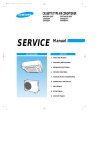
SYSTEM AIR CONDITIONER
INDOOR UNIT
OUTDOOR UNIT
GH052EAM
GH070EAM
UH052EAMT
UH070EAMT
SERVICE
SYSTEM AIR CONDITIONER
Manual
CONTENTS
1. Product Specifications
2. Disassembly and Reassembly
3. Set Up the Model Option
4. Troubleshooting
5. Exploded Views and Parts List
6. Block Diagram
7. Wiring Diagram
8. Schematic Diagram
DB98_16284A(1)_1
2/17/04 10:32 AM
Page 1
1. Product Specifications
1-1 Table
MODEL
INDOOR UNIT
GH052EAM
GH070EAM
OUTDOOR UNIT
UH052EAMT
UH070EAMT
BTU/hr
18,700
23,900
Watts
5,500
7,000
BTU/hr
20,400
26,300
Watts
6,000
7,700
Cooling
Capacity
Heating
Power Supply
Power Input
Running Current
Fan Speed
Air Circulation
Indoor Unit
Noise Level
(Sound Pressure)
Heat Exchanger
1ø, 220~240V~, 50Hz
1ø, 220~240V~, 50Hz
Cooling
Watts
1,750
2,350
Heating
Watts
1,800
2,500
Cooling
A
7.7
10.5
Heating
A
8.0
11.0
U-High
r.p.m
-
-
High
r.p.m
1,315
1,350
Mid
r.p.m
1,210
1,245
Low
r.p.m
1,105
1,140
High
m / min
14
14
Mid
m3 / min
12
12
3
Low
m / min
10
10.5
High
dB(A)
45
46
Mid
dB(A)
44
45
Low
dB(A)
43
44
3
Type
Slit-fin coil
Slit-fin coil
Row x Stages x Fin Pitch
2 x 10 x 1.3(580mm)
3 x 10 x 1.5(580mm)
Cross Flow Fan
Cross Flow Fan
Fan
Dimension
Weight
Fan Speed
Type
Motor Output
W
28
28
H
mm
230
230
W
mm
918
918
D
mm
575
575
Net / Gross
kg
21 / 25
22 / 26
High
r.p.m
750
850
r.p.m
400
340
dB(A)
61
61
Propeller Fan
Propeller Fan
60
73
Low
Sound Pressure Level
Type
Fan
Motor Output
Outdoor Unit
Compressor
W
Type
Rotary
Rotary
Model
NN21VBAMT
NN29VACMT
Motor Output
kW
Protection
Heat Exchanger
1.9
Internal
Type
Slit-fin coil
Slit-fin coil
Row x Stages x Fin Pitch
2 x 28 x 1.5
2 x 28 x 1.5
Control
EEV
EEV
Type
R410A
R410A
1,550
1,650
Refrigerant
Charge
Samsung Electronics
1.3
Internal
g
1
DB98_16284A(1)_1
2/17/04 10:32 AM
Page 2
Table(cont.)
MODEL
Outdoor Unit
Dimension
Weight
Indoor Unit
Condition
Outdoor Unit
Pipe O.D. Size
Piping
INDOOR UNIT
GH052EAM
GH070EAM
OUTDOOR UNIT
UH052EAMT
UH070EAMT
H
mm
648
648
W
mm
880
880
D
mm
310
310
Net / Gross
kg
67 / 72
69 / 74
Cool(DB/WB)
˚C
27 / 19
27 / 19
Heat(DB/WB)
˚C
20 / 15
20 / 15
Cool(DB/WB)
˚C
35 / 24
35 / 24
Heat(DB/WB)
˚C
7/6
7/6
Liquid
mm(inch)
6.35(1/4")
6.35(1/4")
Gas
mm(inch)
12.7(1/2")
15.88(5/8")
Flare
Flare
Connection Method
Between
Height
m
Max. 15
Max. 15
Pipe Length
m
Max. 30
Max. 30
Notice : Air Flow rate : Fan Step Control : Low → Mid → High
2
Samsung Electronics
DB98_16284A(1)_1
2/17/04 11:10 AM
Page 3
2. Disassembly and Reassembly
Stop operation of the air conditioner and remove the power cord before repairing the unit.
2-1 Indoor Unit
No
Parts
1
Front Grille
_ Dust-Collecting
Procedure
Remark
1) Press the "PUSH".
Filter
2) Front Grille Disassembly
(1) Open the Front Grille and pull it up to
the direction in the picture.
(2) Detach the Safe Ring.
3) Filter Disassembly
(1) Detach the Filter by disassembling the
Grille hook.
Samsung Electronics
3
DB98_16284A(1)_1
2/17/04 10:32 AM
Page 4
Disassembly and Reassembly
No
Parts
Procedure
Remark
4) Detach 6 bolts and 2 fixing screws
connected to the Main Body.(Mark point)
5) Unscrew a mark point in the picture,
and detach the Cover from the Panel
with pushing the hook.
6) Detach the connection wires of Step
Motor and the receive part from the wire
of a Main Body.
7) Widen the both hooks of panel hooked
with the Main Body to both sides, and
detach the Panel from the Indoor Unit.
4
Samsung Electronics
DB98_16284A(1)_1
2/17/04 10:32 AM
Page 5
Disassembly and Reassembly
No
Parts
2
Electronic Part
_Indoor & Outdoor
Connecting Cable
Procedure
Remark
1) Unscrew 2 fixing screws of the Case
control and screw of Thermistor wire and
holder.
2) Push the hook, and pull the knob of a
case.
3) Detach the indoor and outdoor connection
wire cable connected to the Terminal.
4) Detach the Fan Motor connection wire,
Heat Exchanger Sensor connection wire,
and the Drain Pump Float S/W connection
wire from the connecter.
5) Detach the Control Box from the main body.
Samsung Electronics
5
DB98_16284A(1)_1
2/17/04 10:32 AM
Page 6
Disassembly and Reassembly
No
Parts
3
EVAP ASS'Y
Procedure
Remark
1) Unsrew 3 screws connected to the main
body and Cover Side.
2) Detach the Cover Side if from the main
body.
3) Unscrew 16 screws connected to the Drain
Pan and the main body.(Mark point)
4) Detach the Drain Pan from the main body.
5) Unscrew 4 Heat Exchanger screws
connected to the cabinet body and cover
Evap Guide.
6
Samsung Electronics
DB98_16284A(1)_1
2/17/04 10:32 AM
Page 7
Disassembly and Reassembly
No
Parts
Procedure
Remark
6) Detach the Drain Pump Sensor from the
holder, and detach the Heat Exchanger
from the main body by pushing it to the
direction of Drain.
4
Fan
&
Motor
1) Unscrew 4 screws of Cover Motor and
Evap Guide connected to the Case Motor.
2) After detaching the Cover Motor by
pushing the hook, detach the Cover Evap
Guide.
3) Detach the Motor and Fan from the case.
(Use M3 wrench when detaching the Motor
from the Fan.)
Samsung Electronics
7
DB98_16284A(1)_1
2/17/04 10:32 AM
Page 8
Disassembly and Reassembly
No
Parts
5
Drain Pump
Procedure
Remark
1) Detach the Drain Hose connected to the
Drain Pump by loosening the spring.
2) Unscrew 4 screws connected to the
Holder Pump and Drain Pump.
3) After connector detaching, detach the Drain
Pump from the holder.
6
8
Other Parts
1) In case of the other parts, detach it like a
picture when necessary.
Samsung Electronics
DB98_16284A(1)_1
2/17/04 10:32 AM
Page 9
Disassembly and Reassembly
No
Parts
7
Front Panel
Procedure
Remark
1) Unscrew 2 screws of the Holder Motor
fixed on the Panel, and detach the Holder
Motor. The Panel, and detach the Holder
Motor.
2) Unscrew 2 screws of the Step-Motor,
and detach the Step-Motor from the Panel.
3) Detach the cable clamp screw.
4) Push the hook of case PCB to the both
sides and detach the case from the Panel.
Samsung Electronics
9
DB98_16284A(1)_1
2/17/04 10:32 AM
Page 10
Disassembly and Reassembly
No
Parts
Procedure
Remark
5) When detaching the PCB from the case,
unscrew the 6 screws and push the hook
at the mark.
6) When detaching the blade, detach the
opposite side first of Step Motor after
turning over the guide on the Panel.
7) When detaching the Blade V, after
detaching the link by pushing, detach
the blade with pushing to the direction
of arrow.
10
Samsung Electronics
DB98_16284A(1)_1
2/17/04 10:32 AM
Page 11
2-2 Outdoor Unit
No
Parts
1
Common Work
Procedure
Remark
1) Loosen the fixing screws and separate the
Cover Control.
2) Separate the connection wire from the
Terminal Block.
3) Loosen the fixing screws and separate the
Upper Cabinet.
4) Loosen the fixing screws and separate the
Front Cabinet.
5) Loosen 2 screws and pull up the
Control Box.
6) Separate the terminal cover and separate
the Comp lead wire.
Samsung Electronics
11
DB98_16284A(1)_1
2/17/04 10:32 AM
Page 12
Disassembly and Reassembly
No
Parts
Procedure
Remark
7) Loosen the fixing screws and separate the
Cabinet Side.
2
Fan
&
Motor
1) Loosen the fixing bolt and separate
the Fan.
2) Loosen 4 fixing bolts to separate
the Motor.
12
Samsung Electronics
DB98_16284A(1)_1
2/17/04 10:32 AM
Page 13
Disassembly and Reassembly
No
Parts
3
Heat Exchanger
&
Compressor
Samsung Electronics
Procedure
Remark
1) Release the refrigerant at first.
2) Disassemble the inlet and outlet pipe
by welding.
3) Loosen the fixing screws of the Heat
Exchanger.
4) Separate the Heat Exchanger.
5) Loosen four bolts of the Compressor.
6) Separate the Compressor.
13
DB98_16284A(1)_1
2/17/04 10:32 AM
Page 14
3. Set Up the Model Option
3-1 Setting Option Setup Method
ex) Option No. :
Step 1 : Enter the Option Setup mode.
1st
Take out the batteries of remote control.
2nd
Press the temp.
button simultaneously and
insert the battery again.
3rd
Make sure the remote controller display shown as
.
Step 2 : Enter the Option Setup mode and select your option according to the following procedure.
1
The default value is
Otherwise, push the
.
button to
.
Every time you push the button, the display panel reads
or
repeatedly.
1
2
Push the
2
3
4
button to set the display panel to
.
Every time you push the button, the display panel reads
...
repeatedly.
3
Push the
button to set the display panel to
.
Every time you push the button, the display panel reads
...
repeatedly.
5
6
4
Push the
button to set the display panel to
.
Every time you push the button, the display panel reads
...
repeatedly.
5
Push the
button to set the display panel to
.
Every time you push the button, the display panel reads
...
repeatedly.
✳ Setting is not required if you must
a value which has a
default.
14
6
Push the
button to set the display panel to
.
Every time you push the button, the display panel reads
...
repeatedly.
Samsung Electronics
DB98_16284A(1)_1
2/17/04 10:32 AM
Page 15
Set up the Model Option
7
Press
button, then the default value is
.
8
Push the
button to set the display panel to
.
Every time you push the button, the display panel reads
...
repeatedly.
7
8
9
9
Push the
button to set the display panel to
.
Every time you push the button, the display panel reads
...
repeatedly.
10
11
10
Push the
12
button to set the display panel to
.
Every time you push the button, the display panel reads
...
repeatedly.
11
Push the
button to set the display panel to
.
Every time you push the button, the display panel reads
...
repeatedly.
12
✳ Setting is not required if you must
a value which has a
default.
Push the
button to set the display panel to
.
Every time you push the button, the display panel reads
...
repeatedly.
Step 3 : Upon completion of the selection, check you made right selections.
Press the Mode Selection key,
to set the display part to and check the display part.
The display part shows
.
Press the Mode Selection key,
The display part shows
to set the display part to
and check the display part.
.
Step 4 : Pressing the ON/OFF button (
)
When pressing the operation ON/OFF key with the direction of remote controller for unit, the sound ''Ding'' or ''Diriring'' is
heard and the OPERATION ICON( ) lamp of the display is flickering at the same time, then the input of option is completed. (If the diriring sound isn't heard, try again pressing the ON/OFF button.)
Step 5 : Unit operation test-run
First, Remove the battery from the remote controller.
Second, Re-insert the battery into the remote controller.
Third, Press ON/OFF button( ) with the direction of remote controller for set.
• Error Mode
1st If all lamps of indoor unit are flickering, Plug out, plug in battery again and press ON/OFF key to retry.
2nd If the unit is not working properly or all lamps are continuously flickering after setting the option code, see if the correct option code is
set up for its model.
Samsung Electronics
15
DB98_16284A(1)_1
2/17/04 10:32 AM
Page 16
Set up the Model Option
■ OPTION ITEMS
REMOTE
CONTROLLER
SEG1
SEG2
SEG3
SEG4
SEG5
SEG6
SEG7
SEG8
SEG9 SEG10 SEG11 SEG12
GH052EAM
0
2
5
4
4
2
1
A
0
3
7
1
GH070EAM
0
2
5
4
4
2
1
c
0
3
8
2
MODEL
16
Samsung Electronics
DB98_16284A(1)_1
2/17/04 10:32 AM
Page 17
4. Troubleshooting
■ Detection of errors
● If an error occurs during the operation, one or more LED flickers and the operation is stopped except the LED.
● If you re-operate the air conditioner, it operates normally at first, then detect an error again.
4-1 LED Display on the indoor unit
Indicators
Abnormal conditions
Operating
Green
Red
Power reset
Error of temp. sensor in indoor unit
(OPEN/SHORT)
Displayed on appropriate indoor unit
which is operating
Error of heat exchanger sensor in indoor unit
Displayed on appropriate indoor unit
which is operating
Error of outdoor temp. sensor
Error of COND sensor
Error of DISCHARGE sensor
Displayed on appropriate indoor unit
which is operating
Displayed on outdoor unit
1. No communication for 2 minutes between
indoor unit and outdoor unit
(communication error for more than
2 minutes)
2. Indoor unit receiving the communication error
from outdoor unit
3. Outdoor unit tracking 3 minute error
4. When sending the communication error from
outdoor unit the mismatching of the
communication numbers and installed
numbers after completion of tracking.(communication error for more than 2 minutes)
1. Error of indoor unit: Displayed on
the indoor unit regardless of
operation
2. Error of outdoor unit: Displayed on
the indoor unit which is operating
Communication error between indoor units
Self-diagnostic error
(including the indoor unit not detected)
1. Error of electronic expansion valve close
2. Error of electronic expansion valve open
3. 2nd detection of high temp. COND
4. 2nd detection of high temp.
DISCHARGE
5. Error of reverse phase
6. Compressor down due to 6th detection of
freezing
Displayed on appropriate indoor unit
which is operating
Displayed on outdoor unit
Error of float switch
Error of setting option switches for optional
accessories
EEPROM error
EEPROM option error
- If you turn off the air conditioner when the LED is flickering, the LED is also turned off.
- If you re-operate the air conditioner, it operates normally at first, then detect an error again.
Samsung Electronics
: On
: Flickering
: Off
17
DB98_16284A(1)_1
2/17/04 10:32 AM
Page 18
4-2 Outdoor Unit
If an error occurs during the operation, it is displayed on the outdoor unit PCB.
Display
Explanation
High temp. of Discharge (Protection control)
Remark
Error about protection
control of outdoor unit
High temp. of outdoor heat exchanger (Protection control)
COMP DOWN to protect being frozen
Error of momentary power failure (disappears when the unit is Off/On)
Error of OUT TEMP. sensor (OPEN/SHORT)
Error of temp. sensor in outdoor heat exchanger (OPEN/SHORT)
Errors about outdoor unit
sensor (OPEN/SHORT)
Detection during the
operation of indoor unit
(Sensing and sending errors
into the communication data)
Error of Discharge TEMP. sensor (OPEN/SHORT)
System Down caused by communication error after completion of tracking
Communication and
indoor unit errors
Mismatching of the indoor unit numbers set with those
communicated after completion of tracking
Error of float switch in indoor unit
Self-diagnosis of indoor and
outdoor unit (x:indoor unit
address)
Error of setting option switches for optional accessories
x
OPEN/SHORT error of room sensor in indoor unit
x
OPEN/SHORT error of evap in sensor in indoor unit
x
Error of fan starting
Displays of operating status
Open error of electronic expansion valve in outdoor unit
(Detected once or more times)
Close error of electronic expansion valve in outdoor unit
(Detected once or more times)
Flicker
Below -5°C when cooling (Outdoor temp.)
Flicker
Over 30°C when heating (Outdoor temp.)
K1, K2, K3, K4,
K5 Flicker
Refer to page 15
The order of priority : E1 → E2 → E4 → P0 → P1 → P5 → P6 → t1 → t2 → t3 → tu → to → G4 → G5 → E3 → qx → rx → vx →
K1, K2, K3, K4, K5
The order of priority : - In case that the same error displays from multi-indoor units, the one having the faster address has the priority.
18
Samsung Electronics
DB98_16284A(1)_1
2/17/04 10:32 AM
Page 19
4-3 Wired remote controller
● If an error occurs,
is displayed on the wired remote controller.
● If you would like to see an error code, press the Test button.
Display
Description
Error of communication between the outdoor unit and the wired
remote controller
Remarks
Communication errors
Error of communication between the indoor unit and the wired
remote controller
x
Open error of electronic expansion valve
x
Close error of electronic expansion valve
x
Error of float switch
x
OPEN/SHORT error of room sensor in indoor unit
x
OPEN/SHORT error of eva in sensor in indoor unit
x
EEPROM error
x
EEPROM option error
Error of outdoor unit
Displays related to indoor unit
(x : 0~F)
For the details, refer to the
installation manual of the
outdoor unit.
The order of priority : EA → Eb → Cx → dx → ox → qx → rx → tx → Ux → Eo
- In case that the same error displays from multi-indoor units, the one having the faster address has the priority.
Samsung Electronics
19
DB98_16284A(1)_1
2/17/04 10:32 AM
Page 20
4-4 Sequence for trouble diagnosis
4-4-1 Outdoor temp. sensor(OPEN/SHORT)
Outdoor unit display
Er → t1 (Outdoor temp. sensor OPEN/SHORT error)
(Operation)
Indoor unit display
How to determine
Reason of error
(Timer)
(Airflow)
(Filter)
Disconnection and short of outdoor temp. sensor
Disconnection or leak of applied sensor
Is not separated the out
temp. sensor connector from PCB?
(CN41)
No
Reoperation
after connect to
connector PCB
Yes
To measure the resistance value
between two terminals after
separating the out temp. sensor
connector from PCB
At this time, Is largely
deviate the resistance value from side
table value?
Yes
Resistance
(kΩ)
70
2.2
60
3.0
50
4.2
40
5.8
30
8.3
20
12.1
10
18.0
0
27.3
-10
43.0
Outdoor unit thermistor
is defective(replace)
No
Check the out temp.
sensor is normal or not by use of
out data display part
➞ Check the temp. data is
normal or not after pressing K4 3 times.
At this time, is occurred the difference
between the out temp. and data?
Temp.
(˚C)
No
PCB and sensor are normal.
To perform the test
operation by use of K2
Yes
Reoperation after PCB replacement
20
Samsung Electronics
DB98_16284A(1)_1
2/17/04 10:32 AM
Page 21
Troubleshooting
4-4-2 Outdoor heat exchanger temp. sensor error(OPEN/SHORT)
Outdoor unit display
Er → t2 (Outdoor heat exchanger temp. sensor error(OPEN/SHORT)
(Operation)
Indoor unit display
How to determine
Reason of error
(Timer)
(Airflow)
(Filter)
Disconnection and short of outdoor heat exchanger temp. sensor
Disconnection or leak of Applied sensor
Is not separated the out
heat exchanger temp. sensor
connector from PCB?(CN41)
No
Reoperation
after connect to
connector PCB
Yes
To measure the resistance value
between two terminals after separating
the out heat exchanger temp.
sensor connector from PCB
Yes
At this time, Is largely
deviate the resistance value from side
table value?
Yes
Yes
Resistance
(kΩ)
70
2.2
60
3.0
50
4.2
40
5.8
30
8.3
20
12.1
10
18.0
0
27.3
-10
43.0
Outdoor heat exchanger
temp. is defective(replace)
No
Check the out temp.
sensor is normal or not by use of
out data display part
➞ Check the temp. data is
normal or not after pressing K4 2 times.
At this time, is occurred the difference
between the out temp. and data?
Temp.
(˚C)
No
PCB and sensor are
normal.
To perform the test
operation by one of K2
Reoperation after PCB replacement
Samsung Electronics
21
DB98_16284A(1)_1
2/17/04 10:32 AM
Page 22
Troubleshooting
4-4-3 Outdoor discharge temp. sensor error(OPEN/SHORT)
Outdoor unit display
Er → t3 (Outdoor discharge temp. sensor OPEN/SHORT error)
(Operation)
Indoor unit display
How to determine
Reason of error
(Timer)
(Airflow)
(Filter)
Disconnection and short of outdoor discharger temp. sensor
Disconnection or leak of Applied sensor
Is not separated the outdoor
discharge temp. sensor connector
from PCB?(CN42)
No
Reoperation
after connect to
connector PCB
Yes
To measure the resistance value
between two terminals after separating
the outdoor discharge temp.
sensor connector from PCB
Yes
At this time, Is largely
deviate the resistance value from
side table value?
Yes
Yes
Resistance
(kΩ)
130
8.9
120
11.2
100
18.5
80
32
60
59
25
200
20
242
10
362
0
553
Outdoor heat exchanger
temp. is defective(replace)
No
Check the out temp.
sensor is normal or not by use of out
data display part
➞ Check the temp. data is
normal or not after pressing K4 1 times.
At this time, is occurred the difference
between the out temp. and data?
Temp.
(˚C)
No
PCB and sensor are normal.
To perform the test
operation by use of K2
Reoperation after PCB replacement
22
Samsung Electronics
DB98_16284A(1)_1
2/17/04 10:32 AM
Page 23
Troubleshooting
4-4-4 Communication error during the operation
Outdoor unit display
Er → E1 (Communication error during the operation)
(Operation)
Indoor unit display
How to determine
Reason of error
(Timer)
(Airflow)
(Filter)
Disconnection and short of communication lines
Communication error between the indoor unit and outdoor unit.
To check the display after
pressing the reset key on outdoor PCB
Multi type
After 2 minutes, to check if PCB address
setting of indoor unit displayed the
communication error among indoor units are
overlapped or not.
(If the indoor unit address is overlapped, the
communication error is occurred.)
- In this case, the communication error is
occurred to over two indoor units set
wrong.
No
When tracking, is there any
indoor answer from display part?
Yes
To measure the 2 lines of outdoor side
by scope after removing the
communication line connecting from
outdoor unit to indoor unit.
If address is no fault,
to exchange the indoor unit PCB after
communication line check.
At this time, is the voltage
between lines spherical wave over DC ±0.7V
like below figure?
No
Yes
Replace PCB after checking
the outdoor unit communication line
and connector
After connecting again the communication
line connecting from outdoor unit to indoor unit,
to remove the communication
connector on indoor unit PCB, and find the
indoor unit preventing communication
through connecting the communication
connectors each by each, and then replace
the indoor unit PCB after line check.
Good
Bad
+0.7V
-0.7V
Samsung Electronics
23
DB98_16284A(1)_1
2/17/04 10:32 AM
Page 24
Troubleshooting
4-4-5 Communication error between indoor and outdoor after initial power input.
Outdoor unit display
Er → E2 (Tracking error)
(Operation)
Indoor unit display
How to determine
Reason of error
(Timer)
(Airflow)
(Filter)
Mismatching the communicating indoor unit and setting switch indoor numbers When outdoor tracking
Communication error between the indoor unit and outdoor unit, and installation number switch
setting miss
Check the setting value of
indoor unit installation number setting
switch of outdoor PCB and actual indoor unit
installation numbers
Is equal indoor unit actual
installation number and installation
number setting switch?
If the indoor unit number installed is one, set the
outdoor unit switch forward to "0", "1"
➞ "0" and "1" spell the connection of an indoor unit.
No
Yes
After setting the indoor unit installation setting
number switch correctly, re-perform the
tracking by pressing the reset key K3 of
outdoor unit PCB
Press the reset key K3 of outdoor unit
PCB and check the display to check the
number of indoor units answering to the
tracking
When tracking, is there any
indoor answer from display part?
Yes
To measure the 2 lines of outdoor unit side by
use of scope after removing the communication
line connecting from outdoor unit to indoor unit
At this time, is the voltage
between lines spherical wave over
DC ±0.7V?
Yes
No
Multi type
After 2 minutes, to check if PCB address setting
of indoor unit displayed the communication error
among indoor units is overlapped or not .
(If the indoor unit address is overlapped, the
communication error is occurred.)
- In this case, the communication error is
occurred to over two indoor units set wrong
If address is no fault,
to exchange the indoor unit PCB after
communication line check.
After connecting again the communication line
connecting from outdoor unit to indoor unit,
to check this communication is reverse or not,
and if there is no fault, to find the indoor unit
preventing communication through connecting
indoor units each by each, and then
exchange the indoor unit PCB after line check
24
Samsung Electronics
DB98_16284A(1)_1
2/17/04 10:32 AM
Page 25
Troubleshooting
4-4-6 Indoor float switching error
Outdoor unit display
Er → E3 (Indoor float switching error )
(Operation)
Indoor unit display
How to determine
(Timer)
(Airflow)
(Filter)
The status continues over 1 minute that indoor unit float switch is opened.
The rising of water level of drain pan due to the disorder of indoor unit drain pump,
Reason of error
the badness of detection sensor
Is the resistance value ∞
when measuring the resistance value
of two terminal after taking out the floating
switch connector connected to indoor
unit PCB? (Open status)
No
Re-assembly the floating switch
connector and perform the reset of
outdoor power(Required the reset of
indoor unit power)
Yes
Is the same error occurred?
No
Yes
Is much the water of drain pan ?
Replace the indoor unit PCB
Yes
No
Normal operation
Reset the indoor unit power
and check the drain pump operation
Check the floating switch bad.
Reset the indoor unit
power after replce
No
Does the drain pump operat?
Yes
Is the terminal voltage
of drain pump PCB about
AC 220V?
Does the water level decrease?
No
No
Yes
Yes
Replace the drain pump
Replace the indoor unit PCB
Normal operation
Replace the drain pump
Samsung Electronics
❋ Note : E3 error should be released when
indoor unit power is reset.
25
DB98_16284A(1)_1
2/17/04 10:33 AM
Page 26
5. Exploded Views and Parts List
5-1 Indoor Unit
1-8
3
1-6
1-7
1-4
1-2
3-2
2
1-5
1-1
1
1-3
3-1
5
4
5-2
11
12
8
5-1
9
10
11
7
8
6
12
14
9
21
13
20
23
25
15
19
18
22
17
24
16
You can search for the updated part code
number through the ITSELF.
URL : http://itself.sec.samsung.co.kr
26
Samsung Electronics
DB98_16284A(1)_1
2/17/04 10:33 AM
Page 27
Exploded Views and Parts List
■
Parts List
No.
Code No.
Description
Q'TY
Specification
GH052EAM
GH070EAM
1
DB93-01811A
ASS'Y CONTROL BOX IN
ASS'Y
1
1
1-1
DB61-01482A
CASE CONTROL
PS(V0), BLK
1
1
1-2
DB61-01236A
BASE TERMINAL
SGCC-M
1
1
1-3
DB93-01480A
ASS'Y MAIN PCB
ASS'Y PCB
1
1
1-4
DB93-01481A
SUB PCB
PCB
1
1
1-5
DB26-10065B
TRANS POWER
1
1
1-6
DB93-01783A
ASS'Y TERMINAL BLOCK 4P
DAF 4P
1
1
1-7
DB93-01784A
ASS'Y TERMINAL BLOCK 6P
DAF S6P
1
1
1-8
DB61-00250A
CLAMP WIRE
NY
2
2
2
DB63-00779A
COVER CONTROL
HIPS
1
1
3
DB91-00232A
ASS'Y DRAIN PAN
ASS'Y DRAIN
1
1
3-1
DB63-00062A
RUBBER DRAIN CAP
NBR
1
1
3-2
DB71-50025A
WIRE HOLDER
NY
1
1
4
DB63-00672A
COVER SIDE LF
PP(INCOMBUSTIBLE), BLK
1
1
5
DB96-02754A
ASS'Y EVAP
FP 1.5 SLIT 3x10
-
1
DB96-03496A
ASS'Y EVAP
FP 1.3 SLIT 2x10
1
-
DB96-02753A
ASS'Y TUBE COLLECTOR
12.7ø
-
1
DB96-03325A
ASS'Y TUBE COLLECTOR
9.52ø
1
-
DB96-02752A
ASS'Y INLETPART
6.35ø CAPI 2.0ø
-
1
DB96-03324A
ASS'Y INLETPART
6.35ø CAPI 2.0ø
1
-
5-1
5-2
6
DB94-00040S
ASS'Y C-F-FAN
ø95 8 ranks, AS+G/F 20%
2
2
7
DB31-00241A
MOTOR ASSY
PFS040AVEB
2
2
8
DB90-01182A
ASS'Y COVER MOTOR
HIPS, INSU
2
2
HIPS, INSU
2
2
2
2
9
DB90-01184A
ASS'Y CASE MOTOR
10
DB95-00131F
ASS'Y SENSOR FLOAT
11
DB90-01183A
ASS'Y COVER EVAP GUIDE
HIPS, INSU
2
2
12
DB90-01185A
ASS'Y CASE FAN SIDE SUB
HIPS, INSU
2
2
13
DB94-00066A
ASS'Y BEARING
BEARING
2
2
14
DB61-01475A
GUIDE CONTROL
HIPS
1
1
15
DB31-00207A
DRAIN PUMP
KS1003SAC
1
1
16
DB61-01293A
HOLDER DRAIN PUMP
HIPS
1
1
17
DB73-00022B
RUBBER DRAIN PUMP
HIPS(HB), BLK
4
4
18
DB94-00371A
ASS'Y DRAIN SOCKET
ASS'Y
1
1
19
DB69-00137A
BAND RING
STS304
1
1
20
DB69-00695A
CUSHION BODY
EPS(GRY)
2
2
21
DB61-01468A
CLIP BRUSH
EPS(GRY)
4
4
22
DB64-00778A
CABINET BASE
SGCC-M 0.7T
1
1
23
DB64-00781A
CABI SIDE RH
SGCC-M 0.7T
1
1
24
DB64-00780A
CABI SIDE LF
SGCC-M 0.7T
1
1
25
DB61-00712A
HOLDER CABI SIDE
SGCC-M 1.0T
4
4
Samsung Electronics
27
DB98_16284A(1)_1
2/17/04 10:33 AM
Page 28
5-2 Panel
7
1
6
12
10
20
8
11
14
9
13
19
16
15
18
17
2
3
4
5
21
28
22
Samsung Electronics
DB98_16284A(1)_1
2/17/04 10:33 AM
Page 29
Exploded Views and Parts List
■
Parts List
No.
Code No.
Description
Q'TY
Specification
PG103M
PG103M1
PG103M2
1
DB64-00777A
PANEL FRONT
ABS
1
1
1
2
DB64-00775A
GRILLE FRONT
ABS
1
1
1
3
DB64-00774A
FILTER INLET AIR
ASS'Y
2
2
2
4
DB61-01297A
CASE OUTLET AIR
HIPS
2
2
2
5
DB66-00415A
BLADE H
HIPS
2
2
2
6
DB66-00402A
BLADE V
PP
16
16
16
7
DB66-00416A
LINK BLADE V
PP
4
4
4
8
DB66-00755A
LATCH DC
ASS'Y
3
3
3
9
DB63-00676A
COVER PANEL
HIPS
1
1
1
10
DB70-00031A
PLATE HANGER
STS304
2
2
2
11
DB31-10153D
MOTOR STEP
ASS'Y
2
2
2
12
DB61-00535A
HOLDER MOTOR
HIPS V0 BLK
2
2
2
13
DB39-00874C
C/W MOTOR STEP LONG
UL1007
1
1
1
14
DB39-00874B
C/W MOTOR STEP SHORT
UL1007
1
1
1
15
DB93-01666A
PCB DISPLAY
1
1
1
16
DB39-00875A
C/W DISPLAY
UL1007
1
1
1
17
DB64-00745A
INLAY WINDOW
PC
1
1
1
18
DB64-00746A
INLAY BUTTON
ABS
1
1
1
19
DB61-01238A
CASE LED PCB
ABS
1
1
1
20
-
CABLE CLAMP
4N
2
2
2
21
DB97-00871D
ASS'Y WIRED REMOCON
WIRED
-
1
-
22
DB97-00387F
ASS'Y WIRELESS REMOCON
WIRELESS
-
-
1
Samsung Electronics
29
DB98_16284A(1)_1
2/17/04 10:33 AM
Page 30
5-3 Outdoor Unit
20
1
2
21
22
15
23
16
5
4
24
8
13
25
9-7
9-1
9-3
10
3
11
9-6
9
9-2
9-5
14
12
9-4
17
19
26
18
6
7
30
Samsung Electronics
DB98_16284A(1)_1
2/17/04 10:33 AM
Page 31
Exploded Views and Parts List
■
Parts List
No.
Code No.
Description
Q'TY
Specification
UH052EAMT UH070EAMT
1
DB90-01363A
ASS'Y-COVER TOP
ASS'Y
1
1
2
DB90-01388A
ASS'Y CABINET-FRONT
ASS'Y
1
1
3
DB67-00140A
FAN-PROPELLER
AS+GF20%,OD460,3BLADE
1
1
1
4
DB61-01167A
BRACKET-MOTOR
SGCC-M,T1.6
1
5
DB90-00940B
ASS'Y-PARTITION
ASS'Y
1
1
6
DB95-00455A
ASS'Y COMP
SIAM,NN29VACMT
-
1
DB95-00454A
ASS'Y COMP
SIAM,NN21VBAMT
1
-
DB95-30013T
ASS'Y HEATER COMP
40W
1
1
7
8
DB31-00216A
MOTOR-FAN
OSEM-886SRC(S509)
-
1
DB31-00027G
MOTOR-FAN
OSEM-906SRC(S507)
1
-
DB93-02410A
ASS'Y CONTROL OUT
ASS'Y
-
1
DB93-02410B
ASS'Y CONTROL OUT
ASS'Y
1
-
9-1
DB26-10070A
TRANS-POWER
AC230V,DC17V
1
1
9-2
DB65-00112A
TERMINAL BLOCK-6P
35A 4P,25A 2P
1
1
9-3
3501-001204
RELAY POWER
MUF20CF,2A
1
1
9-4
DB61-30625A
BRACKET-TERMINAL
SGCC-M
1
1
9-5
DB93-40264E
ASS'Y CONTROL BOX OUT
ASS'Y
1
1
9-6
DB61-00152A
CASE-PCB-OUT
T2.5,ABS,BLK
1
1
9-7
2301-001369
C-FILM
3uF/450VAC
1
1
10
2501-001236
C-OIL
30uF/450VAC
-
1
2501-001235
C-OIL
25uF/450VAC
-
1
2501-001240
C-OIL
50uF/450VAC
1
-
9
11
DB32-00021F
THERMISTOR
AWG22,L470,L550
1
1
12
DB32-00071C
THERMISTOR
AWG22,L600
1
1
13
DB61-01685A
BRACKET-CAPACITOR
SGCC-M
-
1
DB69-60008A
BAND-CAPACITOR
SGCC-M
1
-
14
DB93-01855K
ASS'Y PCB MAIN
CEILING OUTDOOR PCB
1
-
DB93-01855J
ASS'Y PCB MAIN
CEILING OUTDOOR PCB
-
1
15
DB90-40176D
ASS'Y COVER CONTROL
ASS'Y
1
1
16
DB90-01189B
ASS'Y-ASS'Y CABI SIDE RH
ASS'Y
1
1
17
DB62-01471A
INSULATION-CLOTH COMP
UH070EAMT
-
1
DB62-02295A
INSULATION-CLOTH COMP
UH052EAMT
1
-
18
19
DB96-02876A
ASS'Y 4WAY VALVE
ASS'Y
-
1
DB96-02877A
ASS'Y 4WAY VALVE
ASS'Y
1
-
DB96-02896A
ASS'Y EEV VALVE
ASS'Y
-
1
DB96-02896B
ASS'Y EEV VALVE
ASS'Y
1
-
20
DB63-00613A
GUARD-COND
SECC-P,T1.6
1
1
21
DB61-01221A
GUIDE-SCREEN
P.E.H 100%,T2.5,1015x615,BLK
1
1
22
DB63-00320A
GUARD-FAN
HSWR,460
1
1
23
DB96-02849A
ASS'Y COND UNIT
UH070EAMT,UH052EAMT
1
1
24
DB96-02936A
ASS'Y COLLECTOR IN
ASS'Y
1
1
25
DB96-02937A
ASS'Y COLLECTOR OUT
ASS'Y
1
1
26
DB90-01291A
ASS'Y CABINET BASE OUT
ASS'Y
1
1
Samsung Electronics
31
DB98_16284A(1)_1
2/17/04 10:33 AM
Page 32
6. Block Diagram
Up and down STEP MOTOR
Room temp. SENSOR
pipe sensor
pipe outlet sensor
MAIN PCB
Indoor left and right FAN RPM
feedback control
Function display part remocon
receiving part
Option saving control
MICOM
Communication(485comm)
Indoor unit ADDRESS setting part
485 comm control
RMC ADDRESS setting part
Blackout restoring function
Room temp. compensation function
Power source comm wrong
connection prevention function
Central control
Vent fan control
-
32
- Wire remocon
- Relay
- Central controller
485 comm applied, room temp. compensation
EEPROM option saving and blackout restoring function
Left and right FAN MOTOR phase control
Power-comm line misconnection prevention function
Cost saving related sub-option separation between indoor unit communication part
Option part sub-development according to the SVC structure
Samsung Electronics
DB98_16284A(1)_1
2/17/04 10:33 AM
Page 33
7. Wiring Diagram
7-1 Indoor Unit
Code No : DB98-09029A
This Document can not be used without Samsung's authorization.
Samsung Electronics
33
DB98_16284A(1)_1
2/17/04 10:33 AM
Page 34
7-2 Outdoor Unit
■ UH052EAMT
Code No : DB98-14410A
This Document can not be used without Samsung's authorization.
34
Samsung Electronics
DB98_16284A(1)_1
2/17/04 10:33 AM
Page 35
Wiring Diagram
■ UH070EAMT
Code No : DB98-14410B
This Document can not be used without Samsung's authorization.
Samsung Electronics
35
DB98_16284A(1)_1
2/17/04 10:33 AM
Page 36
8. Schematic Diagram
8-1 Indoor Unit
This Document can not be used without Samsung's authorization.
36
Samsung Electronics
DB98_16284A(1)_1
2/17/04 10:33 AM
Page 37
8-2 Outdoor Unit
■ UH052EAMT
This Document can not be used without Samsung's authorization.
Samsung Electronics
37
DB98_16284A(1)_1
2/17/04 10:33 AM
Page 38
Schematic Diagram
■ UH070EAMT
This Document can not be used without Samsung's authorization.
38
Samsung Electronics
DB98_16284A(1)_co
2/17/04 10:33 AM
Page 2
ELECTRONICS
This Service Manual is a property of Samsung Electronics Co., Ltd.
Any unauthorized use of Manual can be punished under applicable
International and/or domestic law.
© Samsung Electronics Co., Ltd. Feb. 2004.
Printed in Korea.
Code No. DB98-16284A(1)