1
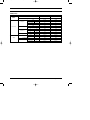
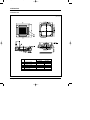
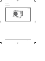
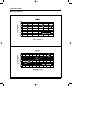
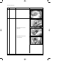
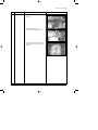
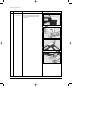
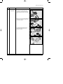
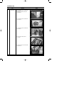
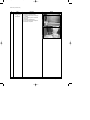
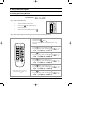
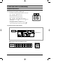
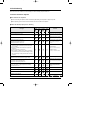
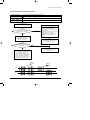
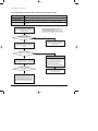
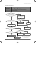
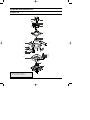
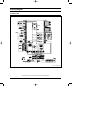
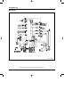
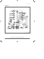
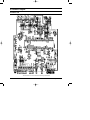
DB98_17072A(1)_CO
04/5/4 1:59 PM
Page 2
CASSETTE TYPE AIR CONDITIONER
INDOOR UNIT
OUTDOOR UNIT
CH052EAM
CH070EAM
UH052EAMT
UH070EAMT
SERVICE
AIR CONDITIONER
Manual
CONTENTS
1. Product Specifications
2. Disassembly and Reassembly
3. Refrigerating Cycle Diagram
4. Set Up the Model Option
5. Control Specification & Troubleshooting
6. Exploded Views and Parts List
7. Block Diagram
8. Wiring Diagram
9. Schematic Diagram
DB98_17072A(1)_1
04/5/4 1:54 PM
Page 1
1. Product Specifications
1-1 Table
INDOOR UNIT
CH052EAM
CH070EAM
OUTDOOR UNIT
UH052EAMT
UH070EAMT
BTU/h
18,700
23,800
W
5,500
7,000
BTU/h
20,400
26,100
MODEL
Cooling
Capacity
Heating
W
6,000
7,700
ø/V/Hz
1/220 ~ 240/50
1/220 ~ 240/50
Cooling
W
1,700
2,400
Heating
W
1,800
2,400
Cooling
A
7.5
10.6
Heating
A
7.9
10.6
H.H
r.p.m
-
-
Power Supply
Power Input
Running
Current
Hi
r.p.m
340
430
Mid
r.p.m
300
330
Low
r.p.m
260
230
H.H
m /min
-
-
Fan Speed
3
Hi
m /min
14
17
Mid
m3/min
12
14
Low
m /min
11
11
Cooling(Hi)
dB(A)
32
37
Heating(Hi)
dB(A)
3
Air Flow
Indoor Unit
Noise Level(Hi)
(Sound Pressure)
Heat Exchanger
3
32
37
Type
Slit
Slit
Row x Stages x Fin pitch
2 x 8 x 1.4mm
2 x 8 x 1.4mm
Type
Turbo
Turbo
Motor Output
W
9.8
20
H
mm
230
230
W
mm
840
840
D
mm
840
840
Net / Gross
kg
26 / 31
26 / 31
Hi
r.p.m
750
850
Fan
Dimensions
Weight
Fan Speed
Low
r.p.m
400
340
m3/min
45
51
Cooling(Hi)
dB(A)
60
60
Heating(Hi)
dB(A)
61
61
Propeller
Propeller
60
73
Rotary
Rotary
NN21VBAMT
NN29VACMT
1.3
1.9
Internal
Internal
Air Flow(Hi)
Noise Level
(Sound Pressure)
Outdoor Unit
Type
Fan
Motor Output
W
Type
Model
Compressor
Motor Output
Protection
Samsung Electronics
kW
1
DB98_17072A(1)_1
04/5/4 1:54 PM
Page 2
Table(cont.)
MODEL
INDOOR UNIT
CH052EAM
CH070EAM
OUTDOOR UNIT
UH052EAMT
UH070EAMT
Type
R410A
R410A
Charge
g
1,550
1,650
Adding Charge
g/m
30
35
Elec.Expansion Valve
Elec.Expansion Valve
Refrigerant
Control
Outdoor Unit
Type
Slit
Slit
Row x Stages x Fin pitch
2 x 28 x 1.5
2 x 28 x 1.5
Heat Exchanger
H
mm
648
648
W
mm
880
880
D
mm
310
310
Net / Gross
kg
67 / 72
69 / 74
Liquid
mm(inch)
6.35(1/4")
6.35(1/4")
Gas
mm(inch)
12.7(1/2")
15.88(5/8")
Flare
Flare
Dimensions
Weight
Pipe O.D Size
Piping
Connection Method
Height
m
Max.15
Max.15
Pipe Length
m
Max.30
Max.30
Between
2
Samsung Electronics
DB98_17072A(1)_1
04/5/4 1:57 PM
Page 3
1-2 Dimensions
1-2-1 Indoor Unit
(Unit : mm)
No.
Model
Name
CH052EAM
Samsung Electronics
CH070EAM
1
Liquid pipe connection
ø6.35(1/4")
ø6.35(1/4")
2
Gas pipe connection
ø12.7(1/2")
ø15.88(5/8")
3
Drain pipe connection
4
Power supply connection
5
Air discharge grille
6
Air suction grille
3
DB98_17072A(1)_1
04/5/4 1:49 PM
Page 4
Product Specifications
1-2-2 Outdoor Unit
880
4
31
0
648
(Unit : mm)
Samsung Electronics
DB98_17072A(1)_1
04/5/4 1:50 PM
Page 5
1-3 Pressure Graph
■ CH052EAM / UH052EAMT
8.78
8.78
8.78
8.78
8.78
8.78
8.78
8.78
8.78
8.78
8.78
8.78
33.13
22.97
22.97
33.13
22.97
21.4
21.11
22.81
22.97
21.11
22.97
22.97
21.11
21.1
21.4
22.81
21.11
21.1
Samsung Electronics
5
DB98_17072A(1)_1
04/5/4 1:50 PM
Page 6
Product Specifications
■ CH070EAM / UH070EAMT
6
Samsung Electronics
DB98_17072A(1)_1
04/5/4 1:50 PM
Page 7
2. Disassembly and Reassembly
Stop operation of the air conditioner and remove the power cord before repairing the unit.
2-1 Indoor Unit
No
Parts
Procedure
1
Front Grille
- Dust-Collecting
Filter
1) Push the tap on the Front Grille to open it.
Remark
2) Disassembly of Front Grille.
(1) Open the Front Grille at about 45˚
degrees and draw it forward.
(2) Disassemble the safety clip.
3) Filter Disassembly
(1) Draw the dust-collecting Filter forward.
(2) Disassemble the Filter.
Samsung Electronics
7
DB98_17072A(1)_1
04/5/4 1:50 PM
Page 8
Disassembly and Reassembly
No
Parts
Procedure
Remark
4) Loosen the 4 bolts slowly.
5) Loosen the bolt of the front net to
disassemble the safety net.
6) Loosen the 4 bolts in the mark
to
uncover the Component Electric Box
cover.
7) Disassemble the 3 cables between the
indoor unit and the Panel.
- Stepping Motor Connector
- Receiving & Display Unit Connector
Option
8
Samsung Electronics
DB98_17072A(1)_1
04/5/4 1:50 PM
Page 9
Disassembly and Reassembly
No
Parts
Procedure
Remark
8) Hold on the two hooks on both sides
of the indoor unit and disassemble the
Front Panel.
9) Take away the disassembled Panel out
of the main body.
2
Electronic Part
- Indoor & Outdoor
Connecting Cable
3
Fan
&
Motor
1) Disconnect all the indoor and outdoor
cables connected to the Terminal Board.
1) Disassemble the Fan Motor wire connector,
thermistor wire connector, and Drain Pump
wire connector.
2) Disassemble the wire connector in the
Capacitor.
Samsung Electronics
9
DB98_17072A(1)_1
04/5/4 1:50 PM
Page 10
Disassembly and Reassembly
No
Parts
Procedure
Remark
3) Disassemble the ground wire.
4) Disassemble the Float Switch wire
connected to the Terminal Port.(F1, F2)
5) Loosen the 8 bolts in the mark
.
6) Loosen a bolt in the arrow direction
and
inside.
7) Disassemble the Drain Cushion from the
main body.
10
Samsung Electronics
DB98_17072A(1)_1
04/5/4 1:50 PM
Page 11
Disassembly and Reassembly
No
Parts
Procedure
Remark
8) Loosen the nut.
9) Lift the fan to disassemble from the Motor.
Take
out
the
washer
Take
out
the
washer
Take
outthe
thewasher
washer
Take
Takeout
Take
out
the
washer
Take
out
the
washer
10) Disassemble the Motor connector wire.
11) Disassemble the ground wire.
Samsung Electronics
11
DB98_17072A(1)_1
04/5/4 1:50 PM
Page 12
Disassembly and Reassembly
No
Parts
Procedure
Remark
12) Loosen 3 nuts to disassemble the Motor.
4
Pump
1) Loosen the 4 bolts of the Drain Pump.
2) Disassemble the Hose from the
Drain Pump.
3) Disassemble the Pump from the
main body Bracket.
12
Samsung Electronics
DB98_17072A(1)_1
04/5/4 1:50 PM
Page 13
Disassembly and Reassembly
No
Parts
5
Heat Exchanger
Procedure
Remark
1) Disassemble the cover pipe beside the
main body.
2) Loosen the 2 bolts fixing the
Heat Exchanger to the indoor unit Base.
3) Disassemble the 4 fixing Brackets of the
Heat Exchanger to disassemble it from the
main body.
Samsung Electronics
13
DB98_17072A(1)_1
04/5/4 1:50 PM
Page 14
Disassembly and Reassembly
No
Parts
6
Front Panel
- Cover Front
14
Procedure
Remark
❈ Do "1", above.
Push 3 Cover Front fixing screws inside the
Front Panel and snap fixing part to detach
the Cover Front.
Samsung Electronics
DB98_17072A(1)_1
04/5/4 1:50 PM
Page 15
Disassembly and Reassembly
No
Parts
Procedure
7
Front Panel
- Stepping Motor
❈ Do "1", above.
1) Loosen each one of fixing screw at the
corner part, (1) cushion side-A and cushion
side-B inside the Front Panel, and then lift it
up.
Remark
2) Remove (1) the screw of Housing Motor L/R
fixed at the corner part of Front Panel inside
and detach (2) Blade-H.
3) (1) Detach the Stepping Motor from the
Housing Motor L/R and (2) detach the
Motor wire connected.
Samsung Electronics
15
DB98_17072A(1)_1
04/5/4 1:50 PM
Page 16
2-2 Outdoor Unit
No
Parts
1
Common Work
Procedure
Remark
1) Loosen the fixing screws and detach the
Cover Control.
2) Detach the connection wire from the
Terminal Block.
3) Loosen the fixing screws and detach the
Upper Cabinet.
4) Loosen the fixing screws and detach the
Front Cabinet.
5) Loosen 2 screws and pull up the
Control Box.
6) Detach the terminal cover and detach the
Comp lead wire.
16
Samsung Electronics
DB98_17072A(1)_1
04/5/4 1:50 PM
Page 17
Disassembly and Reassembly
No
Parts
Procedure
Remark
7) Loosen the fixing screws and detach the
Cabinet Side.
2
Fan
&
Motor
1) Loosen the fixing bolt and detach
the Fan.
2) Loosen 4 fixing bolts to detach
the Motor.
Samsung Electronics
17
DB98_17072A(1)_1
04/5/4 1:50 PM
Page 18
Disassembly and Reassembly
No
Parts
3
Heat Exchanger
&
Compressor
18
Procedure
Remark
1) Release the refrigerant at first.
2) Disassemble the inlet and outlet pipe
by welding.
3) Loosen the fixing screws of the Heat
Exchanger.
4) Detach the Heat Exchanger.
5) Loosen four bolts of the Compressor.
6) Detach the Compressor.
Samsung Electronics
DB98_17072A(1)_1
04/5/4 1:50 PM
Page 19
3. Refrigerating Cycle Diagram
Indoor Unit
Outdoor Unit
❋ Allowable pipe length : Max. 30m
❋ Allowable drop distance : Max. 15m
2-Way valve
Liquid pipe
Filter
Filter
Expansion
valve
Heat
Exchanger
(Condenser)
Heat
Exchanger
(Evaporator)
Gas pipe
3-Way valve
Cooling
Heating
Gas leak check point
Samsung Electronics
4-Way valve
Accumulator
Muffler
Compressor
19
DB98_17072A(1)_1
04/5/4 1:51 PM
Page 20
4. Set Up the Model Option
4-1 Setting Option Setup Method
ex) Option No. :
Step 1 : Enter the Option Setup mode.
1st
Take out the batteries of remote control.
2nd
Press the temp.
button simultaneously and
insert the battery again.
3rd
Make sure the remote control display shown as
.
Step 2 : Enter the Option Setup mode and select your option according to the following procedure.
1
The default value is
Otherwise, push the
.
button to
.
Every time you push the button, the display panel reads
or
repeatedly.
1
2
Push the
2
3
4
button to set the display panel to
.
Every time you push the button, the display panel reads
...
repeatedly.
3
Push the
button to set the display panel to
.
Every time you push the button, the display panel reads
...
repeatedly.
5
6
4
Push the
button to set the display panel to
.
Every time you push the button, the display panel reads
...
repeatedly.
5
Push the
button to set the display panel to
.
Every time you push the button, the display panel reads
...
repeatedly.
✳ Setting is not required if you must
a value which has a
default.
20
6
Push the
button to set the display panel to
.
Every time you push the button, the display panel reads
...
repeatedly.
Samsung Electronics
DB98_17072A(1)_1
04/5/4 1:52 PM
Page 21
Set Up the Model Option
7
Press
button, then the default value is
.
8
Push the
button to set the display panel to
.
Every time you push the button, the display panel reads
...
repeatedly.
7
8
9
9
Push the
button to set the display panel to
.
Every time you push the button, the display panel reads
...
repeatedly.
10
11
10
Push the
12
button to set the display panel to
.
Every time you push the button, the display panel reads
...
repeatedly.
11
Push the
button to set the display panel to
.
Every time you push the button, the display panel reads
...
repeatedly.
12
✳ Setting is not required if you must
a value which has a
default.
Push the
button to set the display panel to
.
Every time you push the button, the display panel reads
...
repeatedly.
Step 3 : Upon completion of the selection, check you made right selections.
Press the Mode Selection key,
to set the display part to and check the display part.
The display part shows
.
Press the Mode Selection key,
The display part shows
to set the display part to
and check the display part.
.
Step 4 : Pressing the ON/OFF button (
)
When pressing the operation ON/OFF key with the direction of remote control for unit, the sound ''Ding'' or ''Diriring'' is
heard and the OPERATION ICON( ) lamp of the display is flickering at the same time, then the input of option is completed. (If the diriring sound isn't heard, try again pressing the ON/OFF button.)
Step 5 : Unit operation test-run
First, Remove the battery from the remote control.
Second, Re-insert the battery into the remote control.
Third, Press ON/OFF button( ) with the direction of remote control for set.
• Error Mode
1st If all lamps of indoor unit are flickering, Plug out, plug in power plug again and press ON/OFF key to retry.
2nd If the unit is not working properly or all lamps are continuously flickering after setting the option code, see if the correct option code is
set up for its model.
Samsung Electronics
21
DB98_17072A(1)_1
04/5/4 1:52 PM
Page 22
Set Up the Model Option
■ OPTION ITEMS
REMOTE
CONTROL SEG1
SEG2
SEG3
SEG4
SEG5
SEG6
SEG7
SEG8
SEG9
SEG10 SEG11 SEG12
MODEL
22
CH052EAM
0
4
5
0
0
0
1
A
0
0
0
0
CH070EAM
0
4
5
0
0
0
1
c
0
0
0
0
Samsung Electronics
DB98_17072A(1)_1
04/5/4 1:52 PM
Page 23
5. Control Specification & Troubleshooting
5-1 Operation Specification
5-1-1 Tracking process marked on display part
4-1-1
• Left numeral is an address that outdoor unit transfers communication.
-
-
-
... -
Left
Right
(Calling indoor unit)
4-1-1
• Right numeral marks address that is answered.
4-1-1
• During the tracking, left calls indoor unit through
- and checks. At this time
... connected indoor unit set on " " and the indoor unit set
address
marked on right.
Right side mark is marked by when left side is
DISPLAY PART (DS1)
.
(If SW02(MAIN) that set indoor unit address is controlled to "
indoor unit number marked on outdoor unit is marked by "
",
".)
5-1-2 Option set part for Outdoor unit PCB
Data display part
DIS1
K1
K2
DIS2
K3
K4
Setting switch for indoor unit
installation numbers
Setting switch for indoor unit installation numbers
Counts of Indoor
Unit Installation
1
2
3
4
5
6
7
8
9
10 11 12 13 14 15
Numbers
of the switch
1
2
3
4
5
6
7
8
9
A
B
C
D
E
F
● Example : When the installed indoor unit is one, control the arrow of switch
forward to ‘0’ or ‘1’ as figure.
Samsung Electronics
23
DB98_17072A(1)_1
04/5/4 1:52 PM
Page 24
Control Specification & Troubleshooting
5-1-3 Setting Up Option Switches
■ KEY
■ Display
DIS 1
K1
K2
K3
DIS 2
K4
RESET DISPLAY
MODE
SEG1
CHECK
MODE
SEG2
ITEM No.
SEG3
SEG4
CURRENT DATA DISPLAY
■ Summary of KEY functions
Function
K4
K3
K2
K1
Number
(Displayed on SEG 3, 4) (Displayed on SEG 3, 4) (Displayed on SEG 3, 4)
(Displayed
on
SEG
3,
4)
of press times
1
Adding refrigerant at
heating mode
Adding refrigerant at
cooling mode
Reset
Displays data
2
Test operation at
heating mode
Test operation at
cooling mode
-
-
3
End
Pump Down for recovery
of refrigerant
-
-
4
-
End
-
-
✳ Use the K1 only for heat pump models.
24
Samsung Electronics
DB98_17072A(1)_1
04/5/4 1:53 PM
Page 25
5-2 Troubleshooting
When error occurs in air conditioner, error code is displayed on indoor unit display lamp and outdoor unit.
5-2-1 Indoor unit LED error diagnosis
■ Error detection and reoperation
■ ● If error occurs during the operation, badness is indicated by LED flickering and all operation is stopped except LED.
■ ● When reoperating by remote control and switch determine the error mode after normal operation.
■ Indoor unit LED lamp display at error detecting
LED lamp display
Error type
Operation
Timer
Air flow
Remarks
Filter
POWER RESET
Room Temperature sensor error
(OPEN/SHORT)
Applied indoor unit error display
(Indoor unit display only during the operation)
Applied indoor unit error display
Indoor heat exchanger temperature sensor error
(Indoor unit display only during the operation)
Outdoor temperature sensor error
Condenser temperature sensor error
Discharge temperature sensor error
The whole indoor unit error display
Outdoor unit separated Display
1. No communication for 2 minutes between indoor unit and
outdoor unit Indoor unit detection (Communication error
over 2 minutes)
2. Indoor unit received communication error signal from
outdoor unit
3. Outdoor unit tracking 3 minutes error
4. After completion of tracking, when outdoor unit transfers
communication error due to mismatch installing numbers
with communicating numbers (Communication error over
2 minutes)
Communication error between indoors
(Operation multi at the same time and group control)
(Indoor unit display only during the
operation)
1. Indoor unit error
(Display is unrelated with operation)
2. Outdoor unit error
(Display is unrelated with operation)
Indoor unit display
Self diagnosis error display(including non-detected indoor unit)
1. Electronic valve closing status error
2. Electronic valve opening status error
Applied indoor unit error Display
Outdoor unit separated Display
1. The sixth detection of high temperature of Cond
2. The sixth detection of high temperature of Discharge
3. Reverse phase error
The whole indoor unit error display
Outdoor unit separated Display
(Indoor unit display only during the operation)
(Indoor unit display only during the
operation)
Detection of floating S/W
Error to the set of option for auxiliary control device
EEPROM ERROR
EEPROM OPTION ERROR
: On
Samsung Electronics
: Flickering
: Off
25
DB98_17072A(1)_1
04/5/4 1:53 PM
Page 26
Control Specification & Troubleshooting
5-2-2 Outdoor Unit
If an error occurs during the operation, it is displayed on the outdoor unit PCB.
Display
Explanation
High temp. of Discharge (Protection control)
Remark
Error about protection
control of outdoor unit
High temp. of outdoor heat exchanger (Protection control)
COMP DOWN to protect being frozen
Error of momentary power failure (disappears when the unit is Off/On)
Error of OUT TEMP. sensor (OPEN/SHORT)
Error of temp. sensor in outdoor heat exchanger (OPEN/SHORT)
Error of Discharge TEMP. sensor (OPEN/SHORT)
System Down caused by communication error after completion of tracking
Errors about outdoor unit
sensor (OPEN/SHORT)
Detection during the
operation of indoor unit
(Sensing and sending errors
into the communication data)
Communication and
indoor unit errors
Mismatching of the indoor unit numbers set with those
communicated after completion of tracking
Error of float switch in indoor unit
Self-diagnosis of indoor and
outdoor unit (x:indoor unit
address)
Error of setting option switches for optional accessories
x
OPEN/SHORT error of room sensor in indoor unit
x
OPEN/SHORT error of evap in sensor in indoor unit
x
Error of fan starting
Displays of operating status
Open error of electronic expansion valve in outdoor unit
(Detected once or more times)
Close error of electronic expansion valve in outdoor unit
(Detected once or more times)
Flicker
Below -5°C when cooling (Outdoor temp.)
Flicker
Over 30°C when heating (Outdoor temp.)
K1, K2, K3, K4,
K5 Flicker
Refer to page 15
The order of priority : E1 → E2 → E4 → E5 → P0 → P1 → P5 → P6 → t1 → t2 → t3 → tu → to → G4 → G5 → E3 → qx → rx → vx →
K1, K2, K3, K4, K5
The order of priority : - In case that the same error displays from multi-indoor units, the one having the faster address has the priority.
26
Samsung Electronics
DB98_19269A(1)_1
9/6/04 3:53 PM
Page 21
5-2 Troubleshooting
5-2-1 Wired remote controller display error occurring
■ If an error occurs,
is displayed on the wired remote controller.
■ If you would like to see an error code, press the Test button.
Display
Description
Compressor down due to protection control of the discharge
temperature sensor
Remarks
Error about protection
control of the outdoor unit
Control due to the condenser temperature sensor when cooling mode
Error of the low pressure switch (Protection control)
Reverse phase error (Protection control)
In removing frost
Error of discharge temperature sensor (Open/Short)
Error about the outdoor unit
sensor (Open/Short)
Detection during the
operation of the indoor unit
(sensing and sending errors into
the communication data)
- System down caused by communication error after completion of
- tracking
Communication and the indoor
unit errors
Error of the outdoor temperature sensor (Open/Short)
Error of condensor temperature sensor (Open/Short)
- Mismatching of the indoor unit numbers set with those
- communication after completion of 5 times tracking
Error of temperature sensor in the indoor unit (Open/Short)
Self-diagnosis of the indoor and
outdoor unit
Error of the heat exchanger sensor in the indoor unit (Open/Short)
Error of electronic expansion valve open in the outdoor unit
(when it is detected more than once)
Error of electronic expansion valve close in the outdoor unit
(when it is detected more than once)
Error of communication between the indoor unit and the wired
remote controller
Wired remote controller errors
Master wired remote controller ↔ Slave wired remote controller
COM1/COM2 Cross-installed error
Error of setting option for wired remote controller COM2
Samsung Electronics
27
DB98_17072A(1)_1
04/5/4 1:53 PM
Page 28
5-3 Sequence for trouble diagnosis
5-3-1 Outdoor temp. sensor(OPEN/SHORT)
Outdoor unit display
Er → t1 (Outdoor temp. sensor OPEN/SHORT error)
(Operation)
Indoor unit display
How to determine
Reason of error
(Timer)
(Airflow)
(Filter)
Disconnection and short of outdoor temp. sensor
Disconnection or leak of applied sensor
Does the out temperature
sensor connected to PCB?
(CN41)
No
Reoperation
after connect to
connector PCB
Yes
Measure the resistance value
between two terminals after
separating the out temp. sensor
connector from PCB
At this time, Is largely
deviate the resistance value from side
table value?
Yes
Resistance
(kΩ)
70
2.2
60
3.0
50
4.2
40
5.8
30
8.3
20
12.1
10
18.0
0
27.3
-10
43.0
Outdoor unit thermistor
is defective(replace)
No
Check the out temp.
sensor is normal or not by use of
out data display part
➞ Check the temp. data is
normal or not after pressing K4 3 times.
At this time, is occurred the difference
between the out temp. and data?
Temp.
(˚C)
No
PCB and sensor are normal.
To perform the test
operation by use of K2
Yes
Reoperation after PCB replacement
28
Samsung Electronics
DB98_17072A(1)_1
04/5/4 1:53 PM
Page 29
Control Specification & Troubleshooting
5-3-2 Outdoor heat exchanger temp. sensor error(OPEN/SHORT)
Outdoor unit display
Er → t2 (Outdoor heat exchanger temp. sensor error(OPEN/SHORT)
(Operation)
Indoor unit display
How to determine
Reason of error
(Timer)
(Airflow)
(Filter)
Disconnection and short of outdoor heat exchanger temp. sensor
Disconnection or leak of Applied sensor
Does the out heat exchanger
temp. sensor connected to PCB?
(CN41)
No
Reoperation
after connect to
connector PCB
Yes
Measure the resistance value
between two terminals after separating
the out heat exchanger temp.
sensor connector from PCB
Yes
At this time, Is largely
deviate the resistance value from side
table value?
Yes
Yes
Resistance
(kΩ)
70
2.2
60
3.0
50
4.2
40
5.8
30
8.3
20
12.1
10
18.0
0
27.3
-10
43.0
Outdoor heat exchanger
temp. is defective(replace)
No
Check the out temp.
sensor is normal or not by use of
out data display part
➞ Check the temp. data is
normal or not after pressing K4 2 times.
At this time, is occurred the difference
between the out temp. and data?
Temp.
(˚C)
No
PCB and sensor are
normal.
To perform the test
operation by one of K2
Reoperation after PCB replacement
Samsung Electronics
29
DB98_17072A(1)_1
04/5/4 1:53 PM
Page 30
Control Specification & Troubleshooting
5-3-3 Outdoor discharge temp. sensor error(OPEN/SHORT)
Outdoor unit display
Er → t3 (Outdoor discharge temp. sensor OPEN/SHORT error)
(Operation)
Indoor unit display
How to determine
Reason of error
(Timer)
(Airflow)
(Filter)
Disconnection and short of outdoor discharger temp. sensor
Disconnection or leak of Applied sensor
Does the outdoor discharge
temp. sensor connected to PCB?
(CN42)
No
Reoperation
after connect to
connector PCB
Yes
Measure the resistance value
between two terminals after separating
the outdoor discharge temp.
sensor connector from PCB
Yes
At this time, Is largely
deviate the resistance value from
side table value?
Yes
Yes
Resistance
(kΩ)
130
8.9
120
11.2
100
18.5
80
32
60
59
25
200
20
242
10
362
0
553
Outdoor heat exchanger
temp. is defective(replace)
No
Check the out temp.
sensor is normal or not by use of out
data display part
➞ Check the temp. data is
normal or not after pressing K4 1 times.
At this time, is occurred the difference
between the out temp. and data?
Temp.
(˚C)
No
PCB and sensor are normal.
To perform the test
operation by use of K2
Reoperation after PCB replacement
30
Samsung Electronics
DB98_17072A(1)_1
04/5/4 1:53 PM
Page 31
Control Specification & Troubleshooting
5-3-4 Communication error during the operation
Outdoor unit display
Er → E1 (Communication error during the operation)
(Operation)
Indoor unit display
How to determine
Reason of error
(Timer)
(Airflow)
(Filter)
Disconnection and short of communication lines
Communication error between the indoor unit and outdoor unit.
Check the display after
pressing the reset key on outdoor PCB
Multi type
After 2 minutes, check if PCB address
setting of indoor unit displayed the
communication error among indoor units are
overlapped or not.
(If the indoor unit address is overlapped, the
communication error is occurred.)
- In this case, the communication error is
occurred to over two indoor units set
wrong.
No
When tracking, is there any
indoor answer from display part?
Yes
Measure the 2 lines of outdoor side
by scope after removing the
communication line connecting from
outdoor unit to indoor unit.
If address is not fault
exchange the indoor unit PCB after
communication line check.
At this time, is the voltage
between lines rectangular wave over DC ±0.7V
like below figure?
No
Yes
Replace PCB after checking
the outdoor unit communication line
and connector
After connecting again the communication
line connecting from outdoor unit to indoor unit,
remove the communication
connector on indoor unit PCB, and find the
indoor unit preventing communication
through connecting the communication
connectors each by each, and then replace
the indoor unit PCB after line check.
Good
Bad
+0.7V
-0.7V
Samsung Electronics
31
DB98_17072A(1)_1
04/5/4 1:53 PM
Page 32
Control Specification & Troubleshooting
5-3-5 Communication error between indoor and outdoor after initial power input.
Outdoor unit display
Er → E2 (Tracking error)
(Operation)
Indoor unit display
How to determine
Reason of error
(Timer)
(Airflow)
(Filter)
Mismatching the communicating indoor unit and setting switch indoor numbers When outdoor tracking
Communication error between the indoor unit and outdoor unit, and installation number switch
setting miss
Check the setting value of
indoor unit installation number setting
switch of outdoor PCB and actual indoor unit
installation numbers
Is equal indoor unit actual
installation number and installation
number setting switch?
If the indoor unit number installed is one, set the
outdoor unit switch forward to "0", "1"
➞ "0" and "1" spell the connection of an indoor unit.
No
Yes
After setting the indoor unit installation setting
number switch correctly, re-perform the
tracking by pressing the reset key K3 of
outdoor unit PCB
Press the reset key K3 of outdoor unit
PCB and check the display to check the
number of indoor units answering to the
tracking
When tracking, is there any
indoor answer from display part?
Yes
To measure the 2 lines of outdoor unit side by
use of scope after removing the communication
line connecting from outdoor unit to indoor unit
At this time, is the voltage
between lines rectangular wave over
DC ±0.7V?
Yes
No
Multi type
After 2 minutes, check if PCB address setting
of indoor unit displayed the communication error
among indoor units is overlapped or not .
(If the indoor unit address is overlapped, the
communication error is occurred.)
- In this case, the communication error is
occurred to over two indoor units set wrong
If address is not fault
exchange the indoor unit PCB after
communication line check.
After connecting again the communication line
connecting from outdoor unit to indoor unit,
check this communication is reverse or not,
and if there is no fault, find the indoor unit
preventing communication through connecting
indoor units each by each, and then
exchange the indoor unit PCB after line check
32
Samsung Electronics
DB98_17072A(1)_1
04/5/4 1:53 PM
Page 33
Control Specification & Troubleshooting
5-3-6 Indoor float switching error
Outdoor unit display
Er → E3 (Indoor float switching error )
(Operation)
Indoor unit display
How to determine
(Timer)
(Airflow)
(Filter)
The status continues over 1 minute that indoor unit float switch is opened.
The rising of water level of drain pan due to the disorder of indoor unit drain pump,
Reason of error
the badness of detection sensor
Is the resistance value ∞
when measuring the resistance value
of two terminal after taking out the floating
switch connector connected to indoor
unit PCB? (Open status)
No
Re-assembly the floating switch
connector and perform the reset of
outdoor power(Required the reset of
indoor unit power)
Yes
Is the same error occurred?
No
Yes
Is much the water of drain pan ?
Replace the indoor unit PCB
Yes
No
Normal operation
Reset the indoor unit power
and check the drain pump operation
Check the floating switch is bad.
Reset the indoor unit
power after replace
No
Does the drain pump operate?
Yes
Is the terminal voltage
of drain pump PCB about
AC 220V?
Does the water level decrease?
No
No
Yes
Yes
Replace the drain pump
Replace the indoor unit PCB
Normal operation
Replace the drain pump
Samsung Electronics
❋ Note : E3 error should be released when
indoor unit power is reset.
33
DB98_17072A(1)_1
04/5/4 1:53 PM
Page 34
6. Exploded Views and Parts List
6-1 Indoor Unit
1
2
5
6
3
4
9
7
8
10
11
12
15
14
19
13
16
20
17
18
24
25
22
23
21
26
27
You can search for the updated part code
number through the ITSELF.
URL : http://itself.sec.samsung.co.kr
34
Samsung Electronics
DB98_17072A(1)_1
04/5/4 1:53 PM
Page 35
Exploded Views and Parts List
■
Parts List
No.
Code No.
Description
Q'TY
Specification
CH052EAM
CH070EAM
1
DB63-00620A
COVER-CONTROL
AFPCH145EA0,HIPS(V0),-,-,-,-,-,-,DPM 5.0HP 4-WAY
1
1
2
DB63-00621A
COVER-CONTROL SUB
AFPCH145EA0,HIPS(HB),-,-,-,-,-,-,DPM 5.0HP 4-WAY
1
1
3
DB93-00843K
ASS'Y PCB MAIN-DPM 4-WAY
DPM 4-WAY,PCB
1
1
4
DB26-10065B
TRANS-POWER
DC17, AC230, 50Hz
1
1
5
DB65-00029M
TERMINAL-BOARD 5P
250V, 20A, 4P
1
1
6
DB65-00029X
TERMINAL BLOCK-6P
250V, 20A, 6P
1
1
7
2301-001369
C-FILM,LEAD-OTHER
3000nF,+10-5%,450V,BK,47x19x28mm,-
1
1
8
DB61-01210A
BASE-CONTROL
AFPCH145EA0,HIPS(V0),-,-,-,-,DPM 5.0HP 4-WAY
1
1
9
DB61-01211A
BASE-CONTROL SUB
AFPCH145EA0,HIPS(HB),-,-,-,-,DPM 5.0HP 4-WAY
1
1
10
DB94-00562A
ASS'Y DRAIN PAN-CUSHION
CH140EZM/XIA,ASS'Y
1
1
11
6021-000131
NUT-HEXAGON
2C, M12, ZPC(YEL), SM20C
1
1
12
DB94-00071B
ASS'Y FAN-TURBO
CH140EZM,Torsional Bush Boss
1
1
13
DB90-01081A
ASS'Y CABINET FRONT
CH070EZM,NEW 4WAY CASSETTE
1
1
14
DB64-00721A
CABINET-SIDE
AFPCH072EA0,SGCC-M,T0.7,-,-,-,-,DPM 7200W 4-WAY
1
1
15
DB90-01082A
ASS'Y CABINET BACK
CH070EZM,NEW 4WAY CASSETTE
1
1
16
DB90-01092A
ASS'Y COVER-PIPE
CH140EZM,CH070EZM,-
1
1
17
DB90-01010A
ASS'Y COVER-DRAIN
CH140EZM,NEW 4WAY CASSETTE
1
1
18
DB94-00345B
ASS'Y-HOSE DRAIN
NO,NO,132.7,NO,R22,-,CH140EZM,-
1
1
19
DB90-01261A
ASS'Y HOLDER-EVAP
CH105EZM,-
1
1
20
DB96-02491G
ASS'Y EVAP-UNIT
CH070EAM,-
-
1
DB96-02491F
ASS'Y EVAP-UNIT
CH052EAM,-
1
-
21
DB90-01083B
ASS'Y BASE IN-CUSHION
AVPCH060B11,-
1
1
22
DB31-00207A
PUMP-DRAIN
-,220V,60Hz,-,-,-
1
1
23
DB73-00022B
RUBBER-PUMP
AKM-2800,NBR(BLK),-,50,14,-,-,-,-,-
1
1
24
DB95-00131C
ASS'Y-SENSOR FLOAT
CH140EZM,NEW 4WAY CASSETTE
1
1
25
DB61-01522A
BRACKET-SWITCH
AVMCH052B11,-,-,-,-,-,-
1
1
26
DB31-00204G
MOTOR FAN
OSME 166SAC(S031),4WAY-P/J,2A,50Hz,230V
-
1
DB31-00204F
MOTOR FAN
OSME 156SAC(S030),4WAY-P/J,2A,50Hz,230V
1
-
DB90-00982A
ASS'Y CABINET-BASE
CH140EZM,NEW 4WAY CASSETTE
1
1
27
Samsung Electronics
35
DB98_17072A(1)_1
04/5/4 1:53 PM
Page 36
6-2 Outdoor Unit
20
1
2
21
22
15
23
16
5
4
24
8
13
25
9-6
9-1
9-3
10
3
11
9-5
9
9-2
9-4
14
12
17
19
26
18
6
7
36
Samsung Electronics
DB98_17072A(1)_1
04/5/4 1:53 PM
Page 37
Exploded Views and Parts List
■
Parts List
No.
Code No.
Description
Q'TY
Specification
UH052EAMT UH070EAMT
1
DB90-01363A
ASS'Y-COVER TOP
ASS'Y
1
1
2
DB90-01293A
ASS'Y CABI-FRONT
ASS'Y,LOGO
1
1
3
DB67-00140A
FAN-PROPELLER
AS+GF20%,OD460,3BLADE
1
1
4
DB61-01167A
BRACKET-MOTOR
SGCC-M,T1.6
1
1
5
DB67-00261A
PARTITION
SGCC-M,T0.8
1
1
6
DB95-00454A
ASS'Y COMP
SIAM,NN29VACMT
-
1
DB95-00455A
ASS'Y COMP
SIAM,NN21VBAMT
1
-
7
DB95-30013T
ASS'Y HEATER COMP
40W
1
1
8
DB31-00216A
MOTOR-FAN
OSEM-886SRC(S509)/YDK80-6X
-
1
9
DB31-00027G
MOTOR-FAN
OSEM-906SRC(S507)/YDK55-6T
1
-
DB93-02410A
ASS'Y CONTROL OUT
ASS'Y
-
1
DB93-02410B
ASS'Y CONTROL OUT
ASS'Y
1
-
9-1
DB26-10070A
TRANS-POWER
AC230V,DC17V
1
1
9-2
DB65-00112A
TERMINAL BLOCK-6P
35A 4P,25A 2P
1
1
9-3
3501-001204
MAGNETIC-SWITCH
MUF20CF,2A
1
1
9-4
DB90-00556B
ASS'Y CASE-CONTROL OUT
ASS'Y
1
1
9-5
DB61-00152A
CASE-PCB-OUT
T2.5,ABS,BLK
1
1
9-6
2301-001369
CAPACITOR-FAN
3uF/450VAC
1
1
10
2501-001236
CAPACITOR-COMP
30uF/450VAC
-
1
2501-001235
CAPACITOR-COMP
25uF/450VAC
-
1
2501-001240
CAPACITOR-COMP
50uF/450VAC
1
-
11
DB32-00021F
THERMISTOR
AWG22,L470,L550
1
1
12
DB32-00071C
THERMISTOR
AWG22,L600
1
1
13
DB61-01685A
BAND-CAPACITOR
SGCC-M
-
1
DB69-60008A
BAND-CAPACITOR
SGCC-M
1
-
DB93-00185K
ASS'Y PCB MAIN-OUT
CEILING OUTDOOR PCB
1
-
DB93-00185J
ASS'Y PCB MAIN-OUT
CEILING OUTDOOR PCB
-
1
14
15
DB63-10490A
COVER-CONTROL
ABS,SC-900073R
1
1
16
DB90-01292B
CABINET-SIDE RH
SECC-P,T0.8
1
1
17
DB62-01471A
INSU-CLOTH COMP
UH070EAMT
-
1
DB62-02295A
INSU-CLOTH COMP
UH052EAMT
1
-
18
19
DB96-02876A
ASS'Y 4WAY VALVE
ASS'Y
-
1
DB96-02877A
ASS'Y 4WAY VALVE
ASS'Y
1
-
DB96-02896A
ASS'Y EEV VALVE
ASS'Y
-
1
DB96-02896B
ASS'Y EEV VALVE
ASS'Y
1
-
20
DB63-00613A
GUARD-COND
SECC-P,T1.6
1
1
21
DB61-01221A
GUIDE-SCREEN
P.E.H 100%,T2.5,1015x615,BLK
1
1
22
DB63-00320A
GUARD-FAN
HSWR,460
1
1
23
DB75-00251A
COND
UH070EAMT,UH052EAMT
1
1
24
DB96-02936A
ASS'Y COLLECTOR IN
ASS'Y
1
1
25
DB96-02937A
ASS'Y COLLECTOR OUT
ASS'Y
1
1
26
DB90-01291A
ASS'Y BASE OUT
ASS'Y
1
1
Samsung Electronics
37
DB98_17072A(1)_1
04/5/4 1:53 PM
Page 38
7. Block Diagram
Up and down STEP MOTOR
Room temp. SENSOR
pipe sensor
pipe outlet sensor
MAIN PCB
Indoor left and right FAN RPM
feedback control
Function display part remote
control receiving part
Option saving control
MICOM
Communication(485comm)
Indoor unit ADDRESS setting part
485 comm control
RMC ADDRESS setting part
Blackout restoring function
Room temp. compensation function
Power source comm wrong
connection prevention function
Central control
Vent fan control
-
38
- Wire remote controller
- Relay
- Central controller
485 comm applied, room temp. compensation
EEPROM option saving and blackout restoring function
Left and right FAN MOTOR phase control
Power-comm line misconnection prevention function
Cost saving related sub-option separation between indoor unit communication part
Option part sub-development according to the SVC structure
Samsung Electronics
DB98_19268A(1)_1
9/6/04 3:54 PM
Page 41
8. Wiring Diagram
8-1 Indoor Unit
Code No : DB98-20413A
This Document can not be used without Samsung's authorization.
Samsung Electronics
39
DB98_17072A(1)_1
04/5/4 1:53 PM
Page 40
8-2 Outdoor Unit
■ UH052EAMT
Code No : DB98-14410A
This Document can not be used without Samsung's authorization.
40
Samsung Electronics
DB98_17072A(1)_1
04/5/4 1:53 PM
Page 41
Wiring Diagram
■ UH070EAMT
Code No : DB98-14410B
This Document can not be used without Samsung's authorization.
Samsung Electronics
41
DB98_17072A(1)_1
04/5/4 1:53 PM
Page 42
9. Schematic Diagram
9-1 Indoor Unit
This Document can not be used without Samsung's authorization.
42
Samsung Electronics
DB98_17072A(1)_1
04/5/4 1:53 PM
Page 43
9-2 Outdoor Unit
■ UH052EAMT
This Document can not be used without Samsung's authorization.
Samsung Electronics
43
DB98_17072A(1)_1
04/5/4 1:53 PM
Page 44
Schematic Diagram
■ UH070EAMT
This Document can not be used without Samsung's authorization.
44
Samsung Electronics
DB98_14413A(1)_1**
10/9/03 5:41 PM
Page 52
UPDATE LOG SHEET
Application date
2005. Feb. 14
Page
35, 39
Part#
DB93-00843K
DB65-00029X
Note(Cause & Solution)
S/Bulletin#
Applied New PCB
Old:DB93-00843H -> New:DB93-00843K
Applied New Terminal Block
Old:DB65-00029U -> New:DB65-00029X
Use this page to keep any special servicing information. (Service Bulletin, etc.)
If only parts number changes, Just change parts number directly on parts list.
And if you need more information, please see the service website.
Itself Solution
Integrated technology supporting electronic library
http://itself.sec.samsung.co.kr
Copyright © 2002
By Samsung Electronics Co., Ltd.
All rights reserved.
This manual may not, in whole or in part, be
copied, photocopied, reproduced, translated, or
converted to any electronic or machine readable
from without prior written permission of
Samsung Electronics Co., Ltd.
DB98_17072A(1)_CO
04/5/4 1:59 PM
Page 1
ELECTRONICS
This Service Manual is a property of Samsung Electronics Co., Ltd.
Any unauthorized use of Manual can be punished under applicable
International and/or domestic law.
© Samsung Electronics Co., Ltd. May. 2004.
Printed in Korea.
Code No. DB98-17072A(1)