1
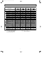
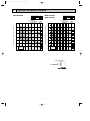
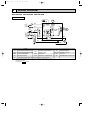
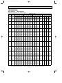
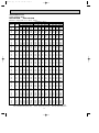
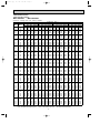
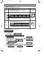
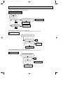
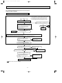
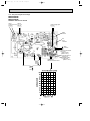
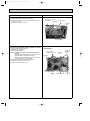
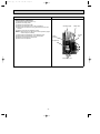
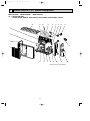
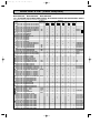
OB387B-1.qxp
07.5.23 2:47 PM
Page 1
Revision B:
● MUH-GA35VB -
SPLIT-TYPE, HEAT PUMP AIR CONDITIONERS
E3
has been added.
Please void OB387 REVISED EDITION-A.
OUTDOOR UNIT
SERVICE MANUAL
HFC
utilized
No. OB387
REVISED EDITION-B
R410A
Wireless type
Models
MUH-GA20VBMUH-GA20VBMUH-GA25VBMUH-GA25VBMUH-GA35VBMUH-GA35VB-
E1
E2
E1
E2
E1
E3
Indoor unit service manual
MSC-GA• VB Series (OB385)
MSC-CA• VB Series (OB393)
MSC-CB• VB Series (OB439)
CONTENTS
MUH-GA20VB
MUH-GA25VB
MUH-GA35VB
1. TECHNICAL CHANGES ····································2
2. PART NAMES AND FUNCTIONS······················3
3. SPECIFICATION·················································3
4. NOISE CRITERIA CURVES ·······························5
5. OUTLINES AND DIMENSIONS ·························6
6. WIRING DIAGRAM ············································7
7. REFRIGERANT SYSTEM DIAGRAM ················8
8. PERFORMANCE CURVES ································9
9. ACTUATOR CONTROL····································19
10. SERVICE FUNCTIONS·····································20
11. TROUBLESHOOTING ······································20
12. DISASSEMBLY INSTRUCTIONS·····················27
13. PARTS LIST······················································30
14. RoHS PARTS LIST···········································32
NOTE:
• This service manual describes technical data of outdoor units.
• RoHS compliant products have <G> mark on the spec name plate.
For servicing of RoHS compliant products, refer to the RoHS Parts List.
OB387B-1.qxp
07.5.23 2:47 PM
Page 2
Revision A:
• MUH-GA20VB-
E2
and MUH-GA25VB-
E3
has been added.
E2
have been added.
Revision B:
• MUH-GA35VB-
1
TECHNICAL CHANGES
MUH-A07YV- E1 ➔MUH-GA20VB- E1
1.
2.
3.
4.
5.
6.
7.
Indication of capacity has been changed. (BTU base ➔ kw)
Dimension of outdoor unit has been changed. (W780mm x H540mm x D255mm ➔ W800mm x H550mm x D285mm)
Stop valve cover has been added.
Outdoor fan motor has been changed. (RC6V20-AB ➔ RA6V21-AD)
Outdoor fan motor capacitor has been changed.
Compressor capacitor has been changed.
Outdoor heat exchanger has been changed. (L-BEND ➔ FLAT)
MUH-A09YV- E1 ➔MUH-GA25VB- E1
1.
2.
3.
4.
5.
6.
7.
Indication of capacity has been changed. (BTU base ➔ kw)
Dimension of outdoor unit has been changed. (W780mm x H540mm x D255mm ➔ W800mm x H550mm x D285mm)
Stop valve cover has been added.
Outdoor fan motor has been changed. (RA6V33-FB ➔ RA6V33-KB)
Outdoor fan motor capacitor has been changed.
Compressor capacitor has been changed.
Outdoor heat exchanger has been changed. (2 Row ➔ 1 Row)
MUH-A12YV- E1 ➔MUH-GA35VB- E1
1.
2.
3.
4.
5.
6.
7.
8.
Indication of capacity has been changed. (BTU base ➔ kw)
Dimension of outdoor unit has been changed. (W780mm x H540mm x D255mm ➔ W800mm x H550mm x D285mm)
Stop valve cover has been added.
Outdoor fan motor has been changed. (RA6V33-FB ➔ RA6V33-KB)
Outdoor fan motor capacitor has been changed.
Compressor capacitor has been changed.
Size of stop valve (gas) has been changed.([12.7 ➔ [9.52)
Outdoor heat exchanger has been changed. (2 Row ➔ 1 Row)
MUH-GA20VB- E1 ➔MUH-GA20VB- E2
1.
2.
3.
4.
5.
Compressor has been changed. (BN092VHST ➔ KN092VDMHC)
Compressor capacitor has been changed.
Capillary tube has been changed.
Refrigerant filling capacity has been changed.
Deicer P.C. board has been changed.
MUH-GA25VB- E1 ➔MUH-GA25VB- E2
1.
2.
3.
4.
5.
Compressor has been changed. (RN104VHSHT ➔ KN104VTMHC)
Compressor capacitor has been changed.
Capillary tube has been changed.
Refrigerant filling capacity has been changed.
Deicer P.C. board has been changed.
MUH-GA35VB- E1 ➔MUH-GA35VB- E3
1. Outdoor heat exchanger has been changed. (1 row ➔ 2 row)
2. Refrigerant filling capacity has been changed.
3. Outdoor unit weight has been changed. (35 kg ➔ 39 kg)
2
OB387B-1.qxp
07.5.23 2:48 PM
2
Page 3
PART NAMES AND FUNCTIONS
OUTDOOR UNIT
ACCESSORIES
MUH-GA20VB
MUH-GA25VB
MUH-GA35VB
MUH-GA20VB
MUH-GA25VB
MUH-GA35VB
(
Air inlet
back : MUH-GA20VB
back and side : MUH-GA25VB
MUH-GA35VB
)
<Outdoor unit: MUH type>
1 Drain socket
1
Piping
Drain hose
Air outlet
Drain outlet
3
SPECIFICATION
Outdoor model
MUH-GA20VB -
Capacity
Electrical
data
Fan
Compressor
motor
Special
remarks
MUH-GA20VB -
Single phase
230V,50Hz
Outdoor unit power supply
Function
Capacity
kW
Dehumidification
R/h
Outdoor air flow
K /h
Power outlet
A
Running current
A
Power input
W
Auxiliary heater
A(kW)
Power factor
%
Starting current
A
Compressor motor current
A
Fan motor current
A
Coefficient of performance (C.O.P)
Model
Output
W
Winding
"
resistance (at 20:)
Model
Winding
"
resistance (at 20:)
Dimensions WOHOD
mm
Weight
kg
Sound level
dB
Fan speed
rpm
Fan speed regulator
Refrigerant filling
kg
capacity (R410A)
Refrigeration oil (Model)
cc
E1
Cooling
2.3
0.9
E2
Single phase
230V,50Hz
Heating
2.5
—
Cooling
2.3
0.9
1,800
10
Heating
2.5
—
1,800
10
3.00
680
2.86
655
3.00
680
100
99
—
2.86
655
—
99
21
100
15.5
2.76
2.62
2.76
0.25
2.62
0.25
3.22
3.62
3.22
3.62
RN092VHSHT
600
C-R 3.87
C-S 6.14
RA6V21-AD
WHT-BLK 366
BLK-RED 274
800o550o285
32
47
745
1
KN092VDMHC
650
C-R 3.62
C-S 5.40
RA6V21-AD
WHT-BLK 366
BLK-RED 274
800o550o285
29
47
745
1
0.65
0.60
350 (NEO22)
350 (NEO22)
NOTE: Test conditions are based on ISO 5151.
Cooling : Indoor DB27°C WB19°C
Outdoor DB35°C WB24°C
Indoor-Outdoor piping length : 5m
Heating : Indoor
Outdoor
3
DB20°C
DB 7°C/WB 6°C
OB387B-1.qxp
07.5.23 2:48 PM
Page 4
MUH-GA25VB
- E1
Single phase
230V,50Hz
Cooling Heating
2.65
3.0
1.1
—
1,902
10
3.43
3.43
785
785
—
100
100
22
3.10
3.10
0.33
3.23
3.66
RN104VHSHT
700
C-R 3.40
C-S 4.56
RA6V33-KB
WHT-BLK 215
BLK-RED 307
800o550o285
MUH-GA25VB
- E2
Single phase
230V,50Hz
Cooling Heating
2.65
3.0
1.1
—
1,902
10
3.43
3.43
785
785
—
100
100
19
3.10
3.10
0.33
3.23
3.66
KN104VTMHC
700
C-R 3.62
C-S 5.40
RA6V33-KB
WHT-BLK 215
BLK-RED 307
800o550o285
MUH-GA35VB
- E1
Single phase
230V,50Hz
Cooling
Heating
3.5
3.7
1.7
—
1,902
10
4.65
4.34
1,050
980
—
98
98
27
4.32
4.01
0.33
3.21
3.63
RN135VHSHT
900
C-R 2.79
C-S 3.36
RA6V33-KB
WHT-BLK 215
BLK-RED 307
800o550o285
MUH-GA35VB
- E3
Single phase
230V,50Hz
Cooling Heating
3.5
3.7
1.7
—
1,902
10
4.65
4.34
1,050
980
—
98
98
27
4.32
4.01
0.33
3.21
3.63
RN135VHSHT
900
C-R 2.79
C-S 3.36
RA6V33-KB
WHT-BLK 215
BLK-RED 307
800o550o285
kg
32
30
35
39
dB
rpm
49
855
1
49
855
1
49
855
1
49
855
1
kg
0.80
0.65
0.80
1.05
cc
350 (NEO22)
350 (NEO22)
620 (NEO22)
620 (NEO22)
Outdoor model
Outdoor unit power supply
Fan
Compressor
motor
Electrical
data
Capacity
Function
Capacity
kW
Dehumidification
R/h
Outdoor air flow
K /h
Power outlet
A
Running current
A
Power input
W
Auxiliary heater
A(kW)
Power factor
%
Starting current
A
Compressor motor current
A
Fan motor current
A
Coefficient of performance (C.O.P)
Model
Output
W
Winding
"
resistance (at 20:)
Model
Winding
"
resistance (at 20:)
mm
Dimensions WOHOD
Special
remarks
Weight
Sound level
Fan speed
Fan speed regulator
Refrigerant filling
capacity (R410A)
Refrigeration oil (Model)
NOTE: Test conditions are based on ISO 5151.
Cooling : Indoor DB27°C WB19°C
Outdoor DB35°C WB24°C
Indoor-Outdoor piping length : 5m
Heating : Indoor
Outdoor
4
DB20°C
DB 7°C/WB 6°C
07.5.23 2:48 PM
Page 5
NOISE CRITERIA CURVES
4
MUH-GA20VB
FUNCTION
SPL(dB(A))
MUH-GA25VB
MUH-GA35VB
LINE
COOLING
HEATING
47
Test conditions,
Cooling :DB35:
Heating :DB 7:
90
COOLING
SPL(dB(A))
LINE
49
HEATING
Test conditions,
Cooling :DB35:
Heating :DB 7:
WB24:
WB 6:
90
80
70
NC-70
60
NC-60
50
NC-50
40
NC-40
30
NC-30
20
FUNCTION
WB24:
WB 6:
OCTAVE BAND SOUND PRESSURE LEVEL, dB re 0.0002 MICRO BAR
OCTAVE BAND SOUND PRESSURE LEVEL, dB re 0.0002 MICRO BAR
OB387B-1.qxp
APPROXIMATE
THRESHOLD OF
HEARING FOR
CONTINUOUS
NOISE
80
70
NC-70
60
NC-60
50
NC-50
40
NC-40
30
NC-30
20
NC-20
10
APPROXIMATE
THRESHOLD OF
HEARING FOR
CONTINUOUS
NOISE
NC-20
10
63
125
250
500
1000
2000
4000
8000
63
BAND CENTER FREQUENCIES, Hz
125
250
500
1000
2000
BAND CENTER FREQUENCIES, Hz
OUTDOOR UNIT
1m
MICROPHONE
5
4000
8000
OB387B-1.qxp
07.5.23 2:48 PM
5
Page 6
OUTLINES AND DIMENSIONS
MUH-GA20VB MUH-GA25VB MUH-GA35VB
Unit: mm
OUTDOOR UNIT
REQUIRED SPACE
Basically open 100mm or more
without any obstruction in front
and on both sides of the unit.
ore
mm
or m
Bolt pitch for
installation
304~325
ore
44
Air in
(MUH-GA25
/GA35VB)
40
2 holes 10X21
e
mm
200
or
or m
Open two sides of left,
right, or rear side.
17.5
Service panel
Air out
23
22.3
Liquid refrigerant pipe joint
Refrigerant pipe (flared) [6.35
Handle
3569
Gas refrigerant pipe joint
Refrigerant pipe (flared) [9.52
99.5
10
164.5
280
150
43-
285
or m
1
100
Drain hole [42
550
344.5
400
Air in
m
00m
170.5
302.5
Service port
500 Bolt pitch for installation
800
6
350
mm
or m
ore
OB387B-1.qxp
07.5.23 2:48 PM
6
Page 7
WIRING DIAGRAM
MUH-GA20VB MUH-GA25VB MUH-GA35VB
OUTDOOR UNIT
21S4
NR61
TB1
L
F61
BRN
CN711
SR61
T61
BLU
N
TAB20
52C
BRN
PE
4
GRN/YLW
CN721
WHT
BLK
RED
C65 3 2 1
BLK
CN661
N
CIRCUIT
BREAKER
POWER SUPPLY
~/N 230V 50Hz
3 2 1
CN730
RED
SR62
TB2
3
DSAR
TO INDOOR
UNIT
CONNECTING
12V
RT61
WHT
3
C
RED S
BLU
MC
C1 BLK
SYMBOL
NAME
C1
COMPRESSOR CAPACITOR
C65
OUTDOOR FAN CAPACITOR
SYMBOL
MF
NAME
OUTDOOR FAN MOTOR
(INNER FUSE)
MF
SYMBOL
T61
R
NAME
TRANSFORMER
TB1,TB2 TERMINAL BLOCK
SURGE ABSORBER
NR61
VARISTOR
21S4
R.V. COIL
F61
FUSE(T2AL250V)
RT61
DEFROST THERMISTOR
52C
COMPRESSOR CONTACTOR
MC
COMPRESSOR(INNER PROTECTOR) SR61,SR62 SOLID STATE RELAY
DSAR
NOTE:1. About the indoor side electric wiring refer to the indoor unit electric wiring diagram for servicing.
2. Use copper conductors only. (For field wiring)
3. Symbols below indicate.
/: Terminal block,
: Connector
7
OB387B-1.qxp
7
07.5.23 2:48 PM
Page 8
REFRIGERANT SYSTEM DIAGRAM
Unit:mm
MUH-GA20VB MUH-GA25VB MUH-GA35VB- E1
OUTDOOR UNIT
Refrigerant pipe [ 9.52
(with heat insulator)
Flared connection
4-way valve
Stop valve
(with service
port)
Muffler
Compressor
Capillary tube
[3.0x[1.4x700 (MUH-GA20VB [3.0x[1.4x900 (MUH-GA20VB [3.0x[1.4x1000(MUH-GA25VB [3.0x[1.6x1500(MUH-GA25VB [3.0x[1.4x500 (MUH-GA35VB Check valve
Strainer
#100
Flared connection
Stop valve Capillary tube
[3.0x[1.4x500
Refrigerant pipe [6.35
[3.0x[1.4x300
[3.0x[1.4x600
(with heat insulator)
[3.0x[1.6x750
Outdoor
heat
exchanger
Defrost
thermistor
RT61
)
)
E1 )
E2 )
E1 )
E1
E2
(MUH-GA20VB
(MUH-GA20VB
(MUH-GA25VB
(MUH-GA25VB
R.V. coil
heating ON
cooling OFF
-
E1
E2
E1
E2
)
, MUH-GA35VB )
)
E1
)
MUH-GA35VB- E3
OUTDOOR UNIT
Refrigerant pipe [ 9.52
(with heat insulator)
Flared connection
4-way valve
Stop valve
(with service
port)
Outdoor
heat
exchanger
Muffler
Compressor
Capillary tube
[3.0x[1.8x600
(2 pcs)
Flared connection
Check valve
Strainer
#100
Capillary tube
[3.0x[1.4x350
Capillary tube
[3.0x[1.4x400
Stop valve
Refrigerant pipe [6.35
(with heat insulator)
R.V. coil
heating ON
cooling OFF
Defrost
thermistor
RT61
Refrigerant flow in cooling
8
Refrigerant flow in heating
OB387B-1.qxp
07.5.23 2:48 PM
Page 9
MAX. REFRIGERANT PIPING LENGTH
Refrigerant piping : m
Max. length
A
Model
MUH-GA20VB
Max. height
B
Piping size O.D : mm
Gas
Length of connecting pipe : m
Liquid
Indoor unit
Outdoor unit
Gas 0.43
Gas 0
Liquid 0.5
Liquid 0
20
MUH-GA25VB
10
MUH-GA35VB
9.52
6.35
25
MAX. HEIGHT DIFFERENCE
Indoor
unit
Refrigerant Piping
Max. length
A
Max. height
B
Outdoor unit
ADDITIONAL REFRIGERANT CHARGE(R410A : g)
Refrigerant piping length (one way)
Model
Outdoor unit precharged
MUH-GA20VB -
E1
650
MUH-GA20VB -
E2
600
MUH-GA25VB -
E1
800
MUH-GA25VB -
E2
650
MUH-GA35VB -
E1
800
MUH-GA35VB -
E3
1050
7m
10m
15m
20m
0
60
160
260
25m
360
Calculation : Xg = 20g/m x (A-7)m
8
PERFORMANCE CURVES
MUH-GA20VB MUH-GA25VB MUH-GA35VB
The standard specifications apply only to the operation of the air conditioner under normal conditions, since operating conditions vary according to the areas where these units are installed. The following information has been provided to clarify the
operating characteristics of the air conditioner under the conditions indicated by the performance curve.
(1) GUARANTEED VOLTAGE
198~264V
(2) AIR FLOW
Air flow should be set at MAX.
(3) MAIN READINGS
}
(1) Indoor intake air wet-bulb temperature :
°CWB
(2) Indoor outlet air wet-bulb temperature :
°CWB
Cooling
(3) Outdoor intake air dry-bulb temperature :
°CDB
(4) Total input:
W
(5) Indoor intake air dry-bulb temperature :
°CDB
Heating
(6) Outdoor intake air wet-bulb temperature :
°CWB
(7) Total input :
W
Indoor air wet/dry-bulb temperature difference on the left side of the chart on page 10 shows the difference between the
indoor intake air wet/dry-bulb temperature and the indoor outlet air wet/dry-bulb temperature for your reference at service.
}
9
OB387B-1.qxp
07.5.23 2:48 PM
Page 10
How to measure the indoor air wet-bulb/dry-bulb temperature difference
1.
2.
3.
4.
5.
6.
7.
Attach at least 2 sets of wet-and dry-bulb thermometers to the indoor air intake as shown in the figure, and at least 2 sets
of wet-and dry-bulb thermometers to the indoor air outlet. The thermometers must be attached to the position where air
speed is high.
Attach at least 2 sets of wet-and dry-bulb thermometers to the outdoor air intake.
Cover the thermometers to prevent direct rays of the sun.
Check that the air filter is cleaned.
Open windows and doors of room.
Press the EMERGENCY OPERATION switch once(twice) to start the EMERGENCY COOL
(HEAT) MODE.
When system stabilizes after more than 15 minutes, measure temperature and take an average temperature.
10 minutes later, measure temperature again and check that the temperature does not change.
INDOOR UNIT
OUTDOOR UNIT
Wet-and dry-bulb
thermometers
Wet-and dry-bulb
thermometers
8-1.CAPACITY AND THE INPUT CURVES
7.1
8.3 9.1
6.4
7.5 8.2
5.8
6.8 7.4
5.1
6.0 6.5
MSC-GA35VB
MUH-GA35VB
9.2 10.0
MSC-GA25VB
MUH-GA25VB
10.011.0
7.8
MSC-GA20VB
MUH-GA20VB
8.5
16.3
16.9 20.3
14.8
15.4 18.4
13.3
13.9 16.6
11.8
12.3 14.7
10.4
10.8 12.9
8.9
9.2 11.1
MSC-GA35VB
MUH-GA35VB
17.8
MSC-GA25VB
MUH-GA25VB
20.0 24.0
18.5 22.1
MSC-GA20VB
MUH-GA20VB
19.2
NOTE:The above curves are for the heating operation without any frost.
10
OB387B-1.qxp
07.5.23 2:48 PM
Page 11
8-2.OUTDOOR LOW PRESSURE AND OUTDOOR UNIT CURRENT
COOL operation
➁
③
Both indoor and outdoor unit are under the same temperature/humidity condition.
Dry-bulb temperature
Relative humidity(%)
20
50
25
60
30
70
Air flow should be set at MAX.
The unit of pressure has been changed to MPa on the international system of units(SI unit system).
f[Gauge] )
The conversion factor is : 1(MPa[Gauge]) =10.2(kgf/f
Outdoor low pressure
(kgf/F[Gauge])(MPa[Gauge])
13
1.3
12
1.2
11
1.1
10
1.0
9
0.9
8
0.8
7
0.7
15
MUH-GA20VB
230V
18 20
50
25
60
230V
3
2
1
15
30 32 35(:)
70(%)
1.3
12
1.2
11
1.1
10
1.0
9
0.9
8
0.8
7
0.7
15
MUH-GA25VB
25
60
30 32
70(%)
2
1
15
35(:)
MUH-GA35VB
12
1.2
11
1.1
10
1.0
9
0.9
8
0.8
7
0.7
15
230V
18 20
50
25
60
30 32
70(%)
Outdoor unit current (A)
Outdoor low pressure
1.3
18 20
50
25
60
30 32
70(%)
35(:)
Ambient temperature(˚C)
Ambient humidity(%)
MUH-GA35VB
6
13
35(:)
3
Ambient temperature(˚C)
Ambient humidity(%)
(kgf/F[Gauge])(MPa[Gauge])
30 32
70(%)
230V
230V
18 20
50
25
60
MUH-GA25VB
4
Outdoor unit current (A)
Outdoor low pressure
13
18 20
50
Ambient temperature(˚C)
Ambient humidity(%)
Ambient temperature(˚C)
Ambient humidity(%)
(kgf/F[Gauge])(MPa[Gauge])
MUH-GA20VB
4
Outdoor unit current (A)
①
230V
5
4
3
15
35(:)
18 20
50
25
60
30 32
70(%)
Ambient temperature(˚C)
Ambient humidity(%)
Ambient temperature(˚C)
Ambient humidity(%)
11
35(:)
OB387B-1.qxp
07.5.23 2:48 PM
Page 12
HEAT operation
Outdoor:Dry bulb temperature 7,15,20°C
Wet bulb temperature 6,12,14.5°C
Condition indoor:Dry bulb temperature 20.0°C
Wet bulb temperature 14.5°C
MUH-GA20VB
4
230V
3
2
5
7
10
15
20 21
25 (:)
Ambient temperature(˚C)
MUH-GA35VB
Outdoor unit current (A)
230V
5
4
7
10
15
20 21
230V
4
3
2
5
7
10
15
20 21
Ambient temperature(˚C)
6
3
5
MUH-GA25VB
5
Outdoor unit current (A)
Outdoor unit current (A)
5
25(:)
Ambient temperature(˚C)
12
25 (:)
OB387B-1.qxp
07.5.23 2:48 PM
Page 13
PERFORMANCE DATA
COOL operation (230V)
MSC-GA20VB
: MUH-GA20VB
CAPACITY : 2.3(kW) SHF : 0.74
INPUT : 715(W)
21
INDOOR INDOOR
Q
SHC
SHF INPUT
DB(:) WB(:)
21
18
2.70 1.51 0.56 572
21
20
2.82 1.24 0.44 601
22
18
2.70 1.62 0.60 572
22
20
2.82 1.35 0.48 601
22
22
2.93 1.06 0.36 622
23
18
2.70 1.73 0.64 572
23
20
2.82 1.47 0.52 601
23
22
2.93 1.17 0.40 622
24
18
2.70 1.84 0.68 572
24
20
2.82 1.58 0.56 601
24
22
2.93 1.29 0.44 622
24
24
3.08 0.99 0.32 651
25
18
2.70 1.95 0.72 572
25
20
2.82 1.69 0.60 601
25
22
2.93 1.41 0.48 622
25
24
3.08 1.11 0.36 651
26
18
2.70 2.05 0.76 572
26
20
2.82 1.80 0.64 601
26
22
2.93 1.52 0.52 622
26
24
3.08 1.23 0.40 651
26
26
3.17 0.89 0.28 686
27
18
2.70 2.16 0.80 572
27
20
2.82 1.92 0.68 601
27
22
2.93 1.64 0.56 622
27
24
3.08 1.36 0.44 651
27
26
3.17 1.02 0.32 686
28
18
2.70 2.27 0.84 572
28
20
2.82 2.03 0.72 601
28
22
2.93 1.76 0.60 622
28
24
3.08 1.48 0.48 651
28
26
3.17 1.14 0.36 686
29
18
2.70 2.38 0.88 572
29
20
2.82 2.14 0.76 601
29
22
2.93 1.88 0.64 622
29
24
3.08 1.60 0.52 651
29
26
3.17 1.27 0.40 686
30
18
2.70 2.49 0.92 572
30
20
2.82 2.25 0.80 601
30
22
2.93 1.99 0.68 622
30
24
3.08 1.73 0.56 651
30
26
3.17 1.40 0.44 686
31
18
2.70 2.59 0.96 572
31
20
2.82 2.37 0.84 601
31
22
2.93 2.11 0.72 622
31
24
3.08 1.85 0.60 651
31
26
3.17 1.52 0.48 686
32
18
2.70 2.70 1.00 572
32
20
2.82 2.48 0.88 601
32
22
2.93 2.23 0.76 622
32
24
3.08 1.97 0.64 651
32
26
3.17 1.65 0.52 686
NOTE
Q :Total capacity (kW)
SHC :Sensible heat capacity (kW)
OUTDOOR DB(:)
25
27
30
Q SHC SHF INPUT Q SHC SHF INPUT Q SHC SHF INPUT
2.59 1.45 0.56 601 2.48 1.39 0.56 629 2.39 1.34 0.56 658
2.70 1.19 0.44 636 2.62 1.15 0.44 651 2.53 1.11 0.44 679
2.59 1.55 0.60 601 2.48 1.49 0.60 629 2.39 1.44 0.60 658
2.70 1.30 0.48 636 2.62 1.26 0.48 651 2.53 1.21 0.48 679
2.83 1.02 0.36 661 2.76 0.99 0.36 679 2.65 0.95 0.36 708
2.59 1.66 0.64 601 2.48 1.59 0.64 629 2.39 1.53 0.64 658
2.70 1.41 0.52 636 2.62 1.36 0.52 651 2.53 1.32 0.52 679
2.83 1.13 0.40 661 2.76 1.10 0.40 679 2.65 1.06 0.40 708
2.59 1.76 0.68 601 2.48 1.69 0.68 629 2.39 1.63 0.68 658
2.70 1.51 0.56 636 2.62 1.47 0.56 651 2.53 1.42 0.56 679
2.83 1.24 0.44 661 2.76 1.21 0.44 679 2.65 1.16 0.44 708
2.97 0.95 0.32 686 2.90 0.93 0.32 708 2.81 0.90 0.32 744
2.59 1.86 0.72 601 2.48 1.79 0.72 629 2.39 1.72 0.72 658
2.70 1.62 0.60 636 2.62 1.57 0.60 651 2.53 1.52 0.60 679
2.83 1.36 0.48 661 2.76 1.32 0.48 679 2.65 1.27 0.48 708
2.97 1.07 0.36 686 2.90 1.04 0.36 708 2.81 1.01 0.36 744
2.59 1.97 0.76 601 2.48 1.89 0.76 629 2.39 1.82 0.76 658
2.70 1.73 0.64 636 2.62 1.68 0.64 651 2.53 1.62 0.64 679
2.83 1.47 0.52 661 2.76 1.44 0.52 679 2.65 1.38 0.52 708
2.97 1.19 0.40 686 2.90 1.16 0.40 708 2.81 1.12 0.40 744
3.08 0.86 0.28 722 3.04 0.85 0.28 744 2.94 0.82 0.28 765
2.59 2.07 0.80 601 2.48 1.99 0.80 629 2.39 1.91 0.80 658
2.70 1.84 0.68 636 2.62 1.78 0.68 651 2.53 1.72 0.68 679
2.83 1.58 0.56 661 2.76 1.55 0.56 679 2.65 1.48 0.56 708
2.97 1.31 0.44 686 2.90 1.28 0.44 708 2.81 1.23 0.44 744
3.08 0.99 0.32 722 3.04 0.97 0.32 744 2.94 0.94 0.32 765
2.59 2.17 0.84 601 2.48 2.09 0.84 629 2.39 2.01 0.84 658
2.70 1.95 0.72 636 2.62 1.89 0.72 651 2.53 1.82 0.72 679
2.83 1.70 0.60 661 2.76 1.66 0.60 679 2.65 1.59 0.60 708
2.97 1.42 0.48 686 2.90 1.39 0.48 708 2.81 1.35 0.48 744
3.08 1.11 0.36 722 3.04 1.09 0.36 744 2.94 1.06 0.36 765
2.59 2.28 0.88 601 2.48 2.19 0.88 629 2.39 2.10 0.88 658
2.70 2.05 0.76 636 2.62 1.99 0.76 651 2.53 1.92 0.76 679
2.83 1.81 0.64 661 2.76 1.77 0.64 679 2.65 1.69 0.64 708
2.97 1.54 0.52 686 2.90 1.51 0.52 708 2.81 1.46 0.52 744
3.08 1.23 0.40 722 3.04 1.21 0.40 744 2.94 1.18 0.40 765
2.59 2.38 0.92 601 2.48 2.29 0.92 629 2.39 2.20 0.92 658
2.70 2.16 0.80 636 2.62 2.10 0.80 651 2.53 2.02 0.80 679
2.83 1.92 0.68 661 2.76 1.88 0.68 679 2.65 1.80 0.68 708
2.97 1.66 0.56 686 2.90 1.62 0.56 708 2.81 1.57 0.56 744
3.08 1.36 0.44 722 3.04 1.34 0.44 744 2.94 1.30 0.44 765
2.59 2.48 0.96 601 2.48 2.38 0.96 629 2.39 2.30 0.96 658
2.70 2.27 0.84 636 2.62 2.20 0.84 651 2.53 2.13 0.84 679
2.83 2.04 0.72 661 2.76 1.99 0.72 679 2.65 1.90 0.72 708
2.97 1.78 0.60 686 2.90 1.74 0.60 708 2.81 1.68 0.60 744
3.08 1.48 0.48 722 3.04 1.46 0.48 744 2.94 1.41 0.48 765
2.59 2.59 1.00 601 2.48 2.48 1.00 629 2.39 2.39 1.00 658
2.70 2.38 0.88 636 2.62 2.31 0.88 651 2.53 2.23 0.88 679
2.83 2.15 0.76 661 2.76 2.10 0.76 679 2.65 2.01 0.76 708
2.97 1.90 0.64 686 2.90 1.85 0.64 708 2.81 1.80 0.64 744
3.08 1.60 0.52 722 3.04 1.58 0.52 744 2.94 1.53 0.52 765
SHF :Sensible heat factor
DB :Dry-bulb temperature
INPUT :Total power input (W)
WB :Wet-bulb temperature
13
OB387B-1.qxp
07.5.23 2:48 PM
Page 14
PERFORMANCE DATA
COOL operation (230V)
MSC-GA20VB
: MUH-GA20VB
CAPACITY : 2.3(kW) SHF : 0.74
INPUT : 715(W)
OUTDOOR DB(:)
35
40
INDOOR INDOOR
DB(:) WB(:) Q SHC SHF INPUT Q SHC SHF INPUT Q
21
18
2.25 1.26 0.56 701 2.07 1.16 0.56 744 1.99
21
20
2.37 1.04 0.44 729 2.21 0.97 0.44 765 2.13
22
18
2.25 1.35 0.60 701 2.07 1.24 0.60 744 1.99
22
20
2.37 1.14 0.48 729 2.21 1.06 0.48 765 2.13
22
22
2.51 0.90 0.36 758 2.35 0.84 0.36 801 2.27
23
18
2.25 1.44 0.64 701 2.07 1.32 0.64 744 1.99
23
20
2.37 1.23 0.52 729 2.21 1.15 0.52 765 2.13
23
22
2.51 1.00 0.40 758 2.35 0.94 0.40 801 2.27
24
18
2.25 1.53 0.68 701 2.07 1.41 0.68 744 1.99
24
20
2.37 1.33 0.56 729 2.21 1.24 0.56 765 2.13
24
22
2.51 1.10 0.44 758 2.35 1.03 0.44 801 2.27
24
24
2.65 0.85 0.32 787 2.48 0.79 0.32 822 2.42
25
18
2.25 1.62 0.72 701 2.07 1.49 0.72 744 1.99
25
20
2.37 1.42 0.60 729 2.21 1.32 0.60 765 2.13
25
22
2.51 1.20 0.48 758 2.35 1.13 0.48 801 2.27
25
24
2.65 0.95 0.36 787 2.48 0.89 0.36 822 2.42
26
18
2.25 1.71 0.76 701 2.07 1.57 0.76 744 1.99
26
20
2.37 1.52 0.64 729 2.21 1.41 0.64 765 2.13
26
22
2.51 1.30 0.52 758 2.35 1.22 0.52 801 2.27
26
24
2.65 1.06 0.40 787 2.48 0.99 0.40 822 2.42
26
26
2.78 0.78 0.28 815 2.62 0.73 0.28 851 2.54
27
18
2.25 1.80 0.80 701 2.07 1.66 0.80 744 1.99
27
20
2.37 1.61 0.68 729 2.21 1.50 0.68 765 2.13
27
22
2.51 1.40 0.56 758 2.35 1.31 0.56 801 2.27
27
24
2.65 1.16 0.44 787 2.48 1.09 0.44 822 2.42
27
26
2.78 0.89 0.32 815 2.62 0.84 0.32 851 2.54
28
18
2.25 1.89 0.84 701 2.07 1.74 0.84 744 1.99
28
20
2.37 1.71 0.72 729 2.21 1.59 0.72 765 2.13
28
22
2.51 1.50 0.60 758 2.35 1.41 0.60 801 2.27
28
24
2.65 1.27 0.48 787 2.48 1.19 0.48 822 2.42
28
26
2.78 1.00 0.36 815 2.62 0.94 0.36 851 2.54
29
18
2.25 1.98 0.88 701 2.07 1.82 0.88 744 1.99
29
20
2.37 1.80 0.76 729 2.21 1.68 0.76 765 2.13
29
22
2.51 1.60 0.64 758 2.35 1.50 0.64 801 2.27
29
24
2.65 1.38 0.52 787 2.48 1.29 0.52 822 2.42
29
26
2.78 1.11 0.40 815 2.62 1.05 0.40 851 2.54
30
18
2.25 2.07 0.92 701 2.07 1.90 0.92 744 1.99
30
20
2.37 1.90 0.80 729 2.21 1.77 0.80 765 2.13
30
22
2.51 1.70 0.68 758 2.35 1.60 0.68 801 2.27
30
24
2.65 1.48 0.56 787 2.48 1.39 0.56 822 2.42
30
26
2.78 1.22 0.44 815 2.62 1.15 0.44 851 2.54
31
18
2.25 2.16 0.96 701 2.07 1.99 0.96 744 1.99
31
20
2.37 1.99 0.84 729 2.21 1.85 0.84 765 2.13
31
22
2.51 1.81 0.72 758 2.35 1.69 0.72 801 2.27
31
24
2.65 1.59 0.60 787 2.48 1.49 0.60 822 2.42
31
26
2.78 1.34 0.48 815 2.62 1.26 0.48 851 2.54
32
18
2.25 2.25 1.00 701 2.07 2.07 1.00 744 1.99
32
20
2.37 2.08 0.88 729 2.21 1.94 0.88 765 2.13
32
22
2.51 1.91 0.76 758 2.35 1.78 0.76 801 2.27
32
24
2.65 1.69 0.64 787 2.48 1.59 0.64 822 2.42
32
26
2.78 1.45 0.52 815 2.62 1.36 0.52 851 2.54
NOTE
Q :Total capacity (kW)
SHF :Sensible heat factor
SHC :Sensible heat capacity (kW)
INPUT :Total power input (W)
14
43
SHC SHF INPUT
1.11 0.56 758
0.94 0.44 787
1.19 0.60 758
1.02 0.48 787
0.82 0.36 815
1.27 0.64 758
1.11 0.52 787
0.91 0.40 815
1.35 0.68 758
1.19 0.56 787
1.00 0.44 815
0.77 0.32 840
1.43 0.72 758
1.28 0.60 787
1.09 0.48 815
0.87 0.36 840
1.51 0.76 758
1.36 0.64 787
1.18 0.52 815
0.97 0.40 840
0.71 0.28 869
1.59 0.80 758
1.45 0.68 787
1.27 0.56 815
1.06 0.44 840
0.81 0.32 869
1.67 0.84 758
1.53 0.72 787
1.36 0.60 815
1.16 0.48 840
0.91 0.36 869
1.75 0.88 758
1.62 0.76 787
1.45 0.64 815
1.26 0.52 840
1.02 0.40 869
1.83 0.92 758
1.70 0.80 787
1.54 0.68 815
1.35 0.56 840
1.12 0.44 869
1.91 0.96 758
1.79 0.84 787
1.63 0.72 815
1.45 0.60 840
1.22 0.48 869
1.99 1.00 758
1.87 0.88 787
1.72 0.76 815
1.55 0.64 840
1.32 0.52 869
DB :Dry-bulb temperature
WB :Wet-bulb temperature
OB387B-1.qxp
07.5.23 2:48 PM
Page 15
PERFORMANCE DATA
COOL operation (230V)
MSC-GA25VB
: MUH-GA25VB
CAPACITY : 2.65(kW) SHF : 0.70
INPUT : 820(W)
OUTDOOR DB(:)
21
25
27
INDOOR INDOOR
DB(:) WB(:) Q SHC SHF INPUT Q SHC SHF INPUT Q SHC SHF INPUT Q
21
18
3.11 1.62 0.52 656 2.98 1.55 0.52 689 2.86 1.49 0.52 722 2.76
21
20
3.25 1.30 0.40 689 3.11 1.25 0.40 730 3.02 1.21 0.40 746 2.92
22
18
3.11 1.74 0.56 656 2.98 1.67 0.56 689 2.86 1.60 0.56 722 2.76
22
20
3.25 1.43 0.44 689 3.11 1.37 0.44 730 3.02 1.33 0.44 746 2.92
22
22
3.38 1.08 0.32 713 3.26 1.04 0.32 759 3.18 1.02 0.32 779 3.05
23
18
3.11 1.87 0.60 656 2.98 1.79 0.60 689 2.86 1.72 0.60 722 2.76
23
20
3.25 1.56 0.48 689 3.11 1.49 0.48 730 3.02 1.45 0.48 746 2.92
23
22
3.38 1.22 0.36 713 3.26 1.17 0.36 759 3.18 1.14 0.36 779 3.05
24
18
3.11 1.99 0.64 656 2.98 1.91 0.64 689 2.86 1.83 0.64 722 2.76
24
20
3.25 1.69 0.52 689 3.11 1.62 0.52 730 3.02 1.57 0.52 746 2.92
24
22
3.38 1.35 0.40 713 3.26 1.30 0.40 759 3.18 1.27 0.40 779 3.05
24
24
3.55 0.99 0.28 746 3.42 0.96 0.28 787 3.34 0.93 0.28 812 3.23
25
18
3.11 2.12 0.68 656 2.98 2.03 0.68 689 2.86 1.95 0.68 722 2.76
25
20
3.25 1.82 0.56 689 3.11 1.74 0.56 730 3.02 1.69 0.56 746 2.92
25
22
3.38 1.49 0.44 713 3.26 1.43 0.44 759 3.18 1.40 0.44 779 3.05
25
24
3.55 1.14 0.32 746 3.42 1.09 0.32 787 3.34 1.07 0.32 812 3.23
26
18
3.11 2.24 0.72 656 2.98 2.15 0.72 689 2.86 2.06 0.72 722 2.76
26
20
3.25 1.95 0.60 689 3.11 1.87 0.60 730 3.02 1.81 0.60 746 2.92
26
22
3.38 1.62 0.48 713 3.26 1.56 0.48 759 3.18 1.53 0.48 779 3.05
26
24
3.55 1.28 0.36 746 3.42 1.23 0.36 787 3.34 1.20 0.36 812 3.23
26
26
3.66 0.88 0.24 787 3.55 0.85 0.24 828 3.50 0.84 0.24 853 3.39
27
18
3.11 2.37 0.76 656 2.98 2.27 0.76 689 2.86 2.18 0.76 722 2.76
27
20
3.25 2.08 0.64 689 3.11 1.99 0.64 730 3.02 1.93 0.64 746 2.92
27
22
3.38 1.76 0.52 713 3.26 1.69 0.52 759 3.18 1.65 0.52 779 3.05
27
24
3.55 1.42 0.40 746 3.42 1.37 0.40 787 3.34 1.34 0.40 812 3.23
27
26
3.66 1.02 0.28 787 3.55 0.99 0.28 828 3.50 0.98 0.28 853 3.39
28
18
3.11 2.49 0.80 656 2.98 2.39 0.80 689 2.86 2.29 0.80 722 2.76
28
20
3.25 2.21 0.68 689 3.11 2.12 0.68 730 3.02 2.05 0.68 746 2.92
28
22
3.38 1.89 0.56 713 3.26 1.83 0.56 759 3.18 1.78 0.56 779 3.05
28
24
3.55 1.56 0.44 746 3.42 1.50 0.44 787 3.34 1.47 0.44 812 3.23
28
26
3.66 1.17 0.32 787 3.55 1.14 0.32 828 3.50 1.12 0.32 853 3.39
29
18
3.11 2.62 0.84 656 2.98 2.50 0.84 689 2.86 2.40 0.84 722 2.76
29
20
3.25 2.34 0.72 689 3.11 2.24 0.72 730 3.02 2.18 0.72 746 2.92
29
22
3.38 2.03 0.60 713 3.26 1.96 0.60 759 3.18 1.91 0.60 779 3.05
29
24
3.55 1.70 0.48 746 3.42 1.64 0.48 787 3.34 1.60 0.48 812 3.23
29
26
3.66 1.32 0.36 787 3.55 1.28 0.36 828 3.50 1.26 0.36 853 3.39
30
18
3.11 2.74 0.88 656 2.98 2.62 0.88 689 2.86 2.52 0.88 722 2.76
30
20
3.25 2.47 0.76 689 3.11 2.37 0.76 730 3.02 2.30 0.76 746 2.92
30
22
3.38 2.16 0.64 713 3.26 2.09 0.64 759 3.18 2.04 0.64 779 3.05
30
24
3.55 1.85 0.52 746 3.42 1.78 0.52 787 3.34 1.74 0.52 812 3.23
30
26
3.66 1.46 0.40 787 3.55 1.42 0.40 828 3.50 1.40 0.40 853 3.39
31
18
3.11 2.86 0.92 656 2.98 2.74 0.92 689 2.86 2.63 0.92 722 2.76
31
20
3.25 2.60 0.80 689 3.11 2.49 0.80 730 3.02 2.42 0.80 746 2.92
31
22
3.38 2.30 0.68 713 3.26 2.22 0.68 759 3.18 2.16 0.68 779 3.05
31
24
3.55 1.99 0.56 746 3.42 1.91 0.56 787 3.34 1.87 0.56 812 3.23
31
26
3.66 1.61 0.44 787 3.55 1.56 0.44 828 3.50 1.54 0.44 853 3.39
32
18
3.11 2.99 0.96 656 2.98 2.86 0.96 689 2.86 2.75 0.96 722 2.76
32
20
3.25 2.73 0.84 689 3.11 2.62 0.84 730 3.02 2.54 0.84 746 2.92
32
22
3.38 2.43 0.72 713 3.26 2.35 0.72 759 3.18 2.29 0.72 779 3.05
32
24
3.55 2.13 0.60 746 3.42 2.05 0.60 787 3.34 2.00 0.60 812 3.23
32
26
3.66 1.76 0.48 787 3.55 1.70 0.48 828 3.50 1.68 0.48 853 3.39
NOTE
Q :Total capacity (kW)
SHF :Sensible heat factor
DB :Dry-bulb temperature
SHC :Sensible heat capacity (kW)
INPUT :Total power input (W)
WB :Wet-bulb temperature
15
SHC
1.43
1.17
1.54
1.28
0.98
1.65
1.40
1.10
1.76
1.52
1.22
0.91
1.87
1.63
1.34
1.03
1.98
1.75
1.46
1.16
0.81
2.09
1.87
1.58
1.29
0.95
2.20
1.98
1.71
1.42
1.09
2.32
2.10
1.83
1.55
1.22
2.43
2.22
1.95
1.68
1.36
2.54
2.33
2.07
1.81
1.49
2.65
2.45
2.19
1.94
1.63
30
SHF INPUT
0.52 754
0.40 779
0.56 754
0.44 779
0.32 812
0.60 754
0.48 779
0.36 812
0.64 754
0.52 779
0.40 812
0.28 853
0.68 754
0.56 779
0.44 812
0.32 853
0.72 754
0.60 779
0.48 812
0.36 853
0.24 877
0.76 754
0.64 779
0.52 812
0.40 853
0.28 877
0.80 754
0.68 779
0.56 812
0.44 853
0.32 877
0.84 754
0.72 779
0.60 812
0.48 853
0.36 877
0.88 754
0.76 779
0.64 812
0.52 853
0.40 877
0.92 754
0.80 779
0.68 812
0.56 853
0.44 877
0.96 754
0.84 779
0.72 812
0.60 853
0.48 877
OB387B-1.qxp
07.5.23 2:48 PM
Page 16
PERFORMANCE DATA
COOL operation (230V)
MSC-GA25VB
: MUH-GA25VB
CAPACITY : 2.65(kW) SHF : 0.70
INDOOR INDOOR
DB(:) WB(:)
21
21
22
22
22
23
23
23
24
24
24
24
25
25
25
25
26
26
26
26
26
27
27
27
27
27
28
28
28
28
28
29
29
29
29
29
30
30
30
30
30
31
31
31
31
31
32
32
32
32
32
NOTE
Q
INPUT : 820(W)
OUTDOOR DB(:)
35
40
SHC SHF INPUT Q SHC SHF INPUT
18
2.60 1.35 0.52 804
20
2.73 1.09 0.40 836
18
2.60 1.45 0.56 804
20
2.73 1.20 0.44 836
22
2.89 0.92 0.32 869
18
2.60 1.56 0.60 804
20
2.73 1.31 0.48 836
22
2.89 1.04 0.36 869
18
2.60 1.66 0.64 804
20
2.73 1.42 0.52 836
22
2.89 1.16 0.40 869
24
3.05 0.85 0.28 902
18
2.60 1.77 0.68 804
20
2.73 1.53 0.56 836
22
2.89 1.27 0.44 869
24
3.05 0.98 0.32 902
18
2.60 1.87 0.72 804
20
2.73 1.64 0.60 836
22
2.89 1.39 0.48 869
24
3.05 1.10 0.36 902
26
3.21 0.77 0.24 935
18
2.60 1.97 0.76 804
20
2.73 1.75 0.64 836
22
2.89 1.50 0.52 869
24
3.05 1.22 0.40 902
26
3.21 0.90 0.28 935
18
2.60 2.08 0.80 804
20
2.73 1.86 0.68 836
22
2.89 1.62 0.56 869
24
3.05 1.34 0.44 902
26
3.21 1.03 0.32 935
18
2.60 2.18 0.84 804
20
2.73 1.97 0.72 836
22
2.89 1.73 0.60 869
24
3.05 1.46 0.48 902
26
3.21 1.15 0.36 935
18
2.60 2.29 0.88 804
20
2.73 2.07 0.76 836
22
2.89 1.85 0.64 869
24
3.05 1.58 0.52 902
26
3.21 1.28 0.40 935
18
2.60 2.39 0.92 804
20
2.73 2.18 0.80 836
22
2.89 1.96 0.68 869
24
3.05 1.71 0.56 902
26
3.21 1.41 0.44 935
18
2.60 2.49 0.96 804
20
2.73 2.29 0.84 836
22
2.89 2.08 0.72 869
24
3.05 1.83 0.60 902
26
3.21 1.54 0.48 935
Q :Total capacity (kW)
SHC :Sensible heat capacity (kW)
Q
2.39 1.24 0.52 853 2.29
2.54 1.02 0.40 877 2.45
2.39 1.34 0.56 853 2.29
2.54 1.12 0.44 877 2.45
2.70 0.86 0.32 918 2.61
2.39 1.43 0.60 853 2.29
2.54 1.22 0.48 877 2.45
2.70 0.97 0.36 918 2.61
2.39 1.53 0.64 853 2.29
2.54 1.32 0.52 877 2.45
2.70 1.08 0.40 918 2.61
2.86 0.80 0.28 943 2.78
2.39 1.62 0.68 853 2.29
2.54 1.42 0.56 877 2.45
2.70 1.19 0.44 918 2.61
2.86 0.92 0.32 943 2.78
2.39 1.72 0.72 853 2.29
2.54 1.53 0.60 877 2.45
2.70 1.30 0.48 918 2.61
2.86 1.03 0.36 943 2.78
3.02 0.73 0.24 976 2.93
2.39 1.81 0.76 853 2.29
2.54 1.63 0.64 877 2.45
2.70 1.41 0.52 918 2.61
2.86 1.14 0.40 943 2.78
3.02 0.85 0.28 976 2.93
2.39 1.91 0.80 853 2.29
2.54 1.73 0.68 877 2.45
2.70 1.51 0.56 918 2.61
2.86 1.26 0.44 943 2.78
3.02 0.97 0.32 976 2.93
2.39 2.00 0.84 853 2.29
2.54 1.83 0.72 877 2.45
2.70 1.62 0.60 918 2.61
2.86 1.37 0.48 943 2.78
3.02 1.09 0.36 976 2.93
2.39 2.10 0.88 853 2.29
2.54 1.93 0.76 877 2.45
2.70 1.73 0.64 918 2.61
2.86 1.49 0.52 943 2.78
3.02 1.21 0.40 976 2.93
2.39 2.19 0.92 853 2.29
2.54 2.04 0.80 877 2.45
2.70 1.84 0.68 918 2.61
2.86 1.60 0.56 943 2.78
3.02 1.33 0.44 976 2.93
2.39 2.29 0.96 853 2.29
2.54 2.14 0.84 877 2.45
2.70 1.95 0.72 918 2.61
2.86 1.72 0.60 943 2.78
3.02 1.45 0.48 976 2.93
SHF :Sensible heat factor
INPUT :Total power input (W)
16
43
SHC SHF INPUT
1.19 0.52 869
0.98 0.40 902
1.28 0.56 869
1.08 0.44 902
0.84 0.32 935
1.38 0.60 869
1.18 0.48 902
0.94 0.36 935
1.47 0.64 869
1.27 0.52 902
1.04 0.40 935
0.78 0.28 964
1.56 0.68 869
1.37 0.56 902
1.15 0.44 935
0.89 0.32 964
1.65 0.72 869
1.47 0.60 902
1.25 0.48 935
1.00 0.36 964
0.70 0.24 996
1.74 0.76 869
1.57 0.64 902
1.36 0.52 935
1.11 0.40 964
0.82 0.28 996
1.83 0.80 869
1.67 0.68 902
1.46 0.56 935
1.22 0.44 964
0.94 0.32 996
1.93 0.84 869
1.76 0.72 902
1.57 0.60 935
1.34 0.48 964
1.05 0.36 996
2.02 0.88 869
1.86 0.76 902
1.67 0.64 935
1.45 0.52 964
1.17 0.40 996
2.11 0.92 869
1.96 0.80 902
1.77 0.68 935
1.56 0.56 964
1.29 0.44 996
2.20 0.96 869
2.06 0.84 902
1.88 0.72 935
1.67 0.60 964
1.41 0.48 996
DB :Dry-bulb temperature
WB :Wet-bulb temperature
OB387B-1.qxp
07.5.23 2:48 PM
Page 17
PERFORMANCE DATA
COOL operation (230V)
MSC-GA35VB
: MUH-GA35VB
CAPACITY : 3.5(kW) SHF : 0.66
INDOOR INDOOR
DB(:) WB(:)
21
18
21
20
22
18
22
20
22
22
23
18
23
20
23
22
24
18
24
20
24
22
24
24
25
18
25
20
25
22
25
24
26
18
26
20
26
22
26
24
26
26
27
18
27
20
27
22
27
24
27
26
28
18
28
20
28
22
28
24
28
26
29
18
29
20
29
22
29
24
29
26
30
18
30
20
30
22
30
24
30
26
31
18
31
20
31
22
31
24
31
26
32
18
32
20
32
22
32
24
32
26
NOTE
Q
4.11
4.29
4.11
4.29
4.46
4.11
4.29
4.46
4.11
4.29
4.46
4.69
4.11
4.29
4.46
4.69
4.11
4.29
4.46
4.69
4.83
4.11
4.29
4.46
4.69
4.83
4.11
4.29
4.46
4.69
4.83
4.11
4.29
4.46
4.69
4.83
4.11
4.29
4.46
4.69
4.83
4.11
4.29
4.46
4.69
4.83
4.11
4.29
4.46
4.69
4.83
INPUT : 1090(W)
OUTDOOR DB(:)
21
25
27
30
SHC SHF INPUT Q SHC SHF INPUT Q SHC SHF INPUT Q SHC SHF INPUT
1.97 0.48 872 3.94 1.89 0.48 916 3.78 1.81 0.48 959 3.64 1.75 0.48 1003
1.54 0.36 916 4.11 1.48 0.36 970 3.99 1.44 0.36 992 3.85 1.39 0.36 1036
2.14 0.52 872 3.94 2.05 0.52 916 3.78 1.97 0.52 959 3.64 1.89 0.52 1003
1.72 0.40 916 4.11 1.65 0.40 970 3.99 1.60 0.40 992 3.85 1.54 0.40 1036
1.25 0.28 948 4.31 1.21 0.28 1008 4.20 1.18 0.28 1036 4.03 1.13 0.28 1079
2.30 0.56 872 3.94 2.21 0.56 916 3.78 2.12 0.56 959 3.64 2.04 0.56 1003
1.89 0.44 916 4.11 1.81 0.44 970 3.99 1.76 0.44 992 3.85 1.69 0.44 1036
1.43 0.32 948 4.31 1.38 0.32 1008 4.20 1.34 0.32 1036 4.03 1.29 0.32 1079
2.47 0.60 872 3.94 2.36 0.60 916 3.78 2.27 0.60 959 3.64 2.18 0.60 1003
2.06 0.48 916 4.11 1.97 0.48 970 3.99 1.92 0.48 992 3.85 1.85 0.48 1036
1.61 0.36 948 4.31 1.55 0.36 1008 4.20 1.51 0.36 1036 4.03 1.45 0.36 1079
1.13 0.24 992 4.52 1.08 0.24 1046 4.41 1.06 0.24 1079 4.27 1.02 0.24 1134
2.63 0.64 872 3.94 2.52 0.64 916 3.78 2.42 0.64 959 3.64 2.33 0.64 1003
2.23 0.52 916 4.11 2.14 0.52 970 3.99 2.07 0.52 992 3.85 2.00 0.52 1036
1.79 0.40 948 4.31 1.72 0.40 1008 4.20 1.68 0.40 1036 4.03 1.61 0.40 1079
1.31 0.28 992 4.52 1.26 0.28 1046 4.41 1.23 0.28 1079 4.27 1.20 0.28 1134
2.80 0.68 872 3.94 2.68 0.68 916 3.78 2.57 0.68 959 3.64 2.48 0.68 1003
2.40 0.56 916 4.11 2.30 0.56 970 3.99 2.23 0.56 992 3.85 2.16 0.56 1036
1.96 0.44 948 4.31 1.89 0.44 1008 4.20 1.85 0.44 1036 4.03 1.77 0.44 1079
1.50 0.32 992 4.52 1.44 0.32 1046 4.41 1.41 0.32 1079 4.27 1.37 0.32 1134
0.97 0.20 1046 4.69 0.94 0.20 1101 4.62 0.92 0.20 1134 4.48 0.90 0.20 1166
2.96 0.72 872 3.94 2.84 0.72 916 3.78 2.72 0.72 959 3.64 2.62 0.72 1003
2.57 0.60 916 4.11 2.47 0.60 970 3.99 2.39 0.60 992 3.85 2.31 0.60 1036
2.14 0.48 948 4.31 2.07 0.48 1008 4.20 2.02 0.48 1036 4.03 1.93 0.48 1079
1.69 0.36 992 4.52 1.63 0.36 1046 4.41 1.59 0.36 1079 4.27 1.54 0.36 1134
1.16 0.24 1046 4.69 1.13 0.24 1101 4.62 1.11 0.24 1134 4.48 1.08 0.24 1166
3.13 0.76 872 3.94 2.99 0.76 916 3.78 2.87 0.76 959 3.64 2.77 0.76 1003
2.74 0.64 916 4.11 2.63 0.64 970 3.99 2.55 0.64 992 3.85 2.46 0.64 1036
2.32 0.52 948 4.31 2.24 0.52 1008 4.20 2.18 0.52 1036 4.03 2.09 0.52 1079
1.88 0.40 992 4.52 1.81 0.40 1046 4.41 1.76 0.40 1079 4.27 1.71 0.40 1134
1.35 0.28 1046 4.69 1.31 0.28 1101 4.62 1.29 0.28 1134 4.48 1.25 0.28 1166
3.29 0.80 872 3.94 3.15 0.80 916 3.78 3.02 0.80 959 3.64 2.91 0.80 1003
2.92 0.68 916 4.11 2.80 0.68 970 3.99 2.71 0.68 992 3.85 2.62 0.68 1036
2.50 0.56 948 4.31 2.41 0.56 1008 4.20 2.35 0.56 1036 4.03 2.25 0.56 1079
2.06 0.44 992 4.52 1.99 0.44 1046 4.41 1.94 0.44 1079 4.27 1.88 0.44 1134
1.55 0.32 1046 4.69 1.50 0.32 1101 4.62 1.48 0.32 1134 4.48 1.43 0.32 1166
3.45 0.84 872 3.94 3.31 0.84 916 3.78 3.18 0.84 959 3.64 3.06 0.84 1003
3.09 0.72 916 4.11 2.96 0.72 970 3.99 2.87 0.72 992 3.85 2.77 0.72 1036
2.68 0.60 948 4.31 2.58 0.60 1008 4.20 2.52 0.60 1036 4.03 2.42 0.60 1079
2.25 0.48 992 4.52 2.17 0.48 1046 4.41 2.12 0.48 1079 4.27 2.05 0.48 1134
1.74 0.36 1046 4.69 1.69 0.36 1101 4.62 1.66 0.36 1134 4.48 1.61 0.36 1166
3.62 0.88 872 3.94 3.47 0.88 916 3.78 3.33 0.88 959 3.64 3.20 0.88 1003
3.26 0.76 916 4.11 3.13 0.76 970 3.99 3.03 0.76 992 3.85 2.93 0.76 1036
2.86 0.64 948 4.31 2.76 0.64 1008 4.20 2.69 0.64 1036 4.03 2.58 0.64 1079
2.44 0.52 992 4.52 2.35 0.52 1046 4.41 2.29 0.52 1079 4.27 2.22 0.52 1134
1.93 0.40 1046 4.69 1.88 0.40 1101 4.62 1.85 0.40 1134 4.48 1.79 0.40 1166
3.78 0.92 872 3.94 3.62 0.92 916 3.78 3.48 0.92 959 3.64 3.35 0.92 1003
3.43 0.80 916 4.11 3.29 0.80 970 3.99 3.19 0.80 992 3.85 3.08 0.80 1036
3.03 0.68 948 4.31 2.93 0.68 1008 4.20 2.86 0.68 1036 4.03 2.74 0.68 1079
2.63 0.56 992 4.52 2.53 0.56 1046 4.41 2.47 0.56 1079 4.27 2.39 0.56 1134
2.13 0.44 1046 4.69 2.06 0.44 1101 4.62 2.03 0.44 1134 4.48 1.97 0.44 1166
Q :Total capacity (kW)
SHC :Sensible heat capacity (kW)
SHF :Sensible heat factor
INPUT :Total power input (W)
17
DB :Dry-bulb temperature
WB :Wet-bulb temperature
OB387B-1.qxp
07.5.23 2:48 PM
Page 18
PERFORMANCE DATA
COOL operation (230V)
MSC-GA35VB
: MUH-GA35VB
CAPACITY : 3.5(kW) SHF : 0.66
INPUT : 1090(W)
OUTDOOR DB(:)
35
40
INDOOR INDOOR
DB(:) WB(:) Q SHC SHF INPUT Q SHC SHF INPUT Q
21
18
3.43 1.65 0.48 1068 3.15 1.51 0.48 1134 3.03
21
20
3.61 1.30 0.36 1112 3.36 1.21 0.36 1166 3.24
22
18
3.43 1.78 0.52 1068 3.15 1.64 0.52 1134 3.03
22
20
3.61 1.44 0.40 1112 3.36 1.34 0.40 1166 3.24
22
22
3.82 1.07 0.28 1155 3.57 1.00 0.28 1221 3.45
23
18
3.43 1.92 0.56 1068 3.15 1.76 0.56 1134 3.03
23
20
3.61 1.59 0.44 1112 3.36 1.48 0.44 1166 3.24
23
22
3.82 1.22 0.32 1155 3.57 1.14 0.32 1221 3.45
24
18
3.43 2.06 0.60 1068 3.15 1.89 0.60 1134 3.03
24
20
3.61 1.73 0.48 1112 3.36 1.61 0.48 1166 3.24
24
22
3.82 1.37 0.36 1155 3.57 1.29 0.36 1221 3.45
24
24
4.03 0.97 0.24 1199 3.78 0.91 0.24 1254 3.68
25
18
3.43 2.20 0.64 1068 3.15 2.02 0.64 1134 3.03
25
20
3.61 1.87 0.52 1112 3.36 1.75 0.52 1166 3.24
25
22
3.82 1.53 0.40 1155 3.57 1.43 0.40 1221 3.45
25
24
4.03 1.13 0.28 1199 3.78 1.06 0.28 1254 3.68
26
18
3.43 2.33 0.68 1068 3.15 2.14 0.68 1134 3.03
26
20
3.61 2.02 0.56 1112 3.36 1.88 0.56 1166 3.24
26
22
3.82 1.68 0.44 1155 3.57 1.57 0.44 1221 3.45
26
24
4.03 1.29 0.32 1199 3.78 1.21 0.32 1254 3.68
26
26
4.24 0.85 0.20 1243 3.99 0.80 0.20 1297 3.87
27
18
3.43 2.47 0.72 1068 3.15 2.27 0.72 1134 3.03
27
20
3.61 2.16 0.60 1112 3.36 2.02 0.60 1166 3.24
27
22
3.82 1.83 0.48 1155 3.57 1.71 0.48 1221 3.45
27
24
4.03 1.45 0.36 1199 3.78 1.36 0.36 1254 3.68
27
26
4.24 1.02 0.24 1243 3.99 0.96 0.24 1297 3.87
28
18
3.43 2.61 0.76 1068 3.15 2.39 0.76 1134 3.03
28
20
3.61 2.31 0.64 1112 3.36 2.15 0.64 1166 3.24
28
22
3.82 1.98 0.52 1155 3.57 1.86 0.52 1221 3.45
28
24
4.03 1.61 0.40 1199 3.78 1.51 0.40 1254 3.68
28
26
4.24 1.19 0.28 1243 3.99 1.12 0.28 1297 3.87
29
18
3.43 2.74 0.80 1068 3.15 2.52 0.80 1134 3.03
29
20
3.61 2.45 0.68 1112 3.36 2.28 0.68 1166 3.24
29
22
3.82 2.14 0.56 1155 3.57 2.00 0.56 1221 3.45
29
24
4.03 1.77 0.44 1199 3.78 1.66 0.44 1254 3.68
29
26
4.24 1.36 0.32 1243 3.99 1.28 0.32 1297 3.87
30
18
3.43 2.88 0.84 1068 3.15 2.65 0.84 1134 3.03
30
20
3.61 2.60 0.72 1112 3.36 2.42 0.72 1166 3.24
30
22
3.82 2.29 0.60 1155 3.57 2.14 0.60 1221 3.45
30
24
4.03 1.93 0.48 1199 3.78 1.81 0.48 1254 3.68
30
26
4.24 1.52 0.36 1243 3.99 1.44 0.36 1297 3.87
31
18
3.43 3.02 0.88 1068 3.15 2.77 0.88 1134 3.03
31
20
3.61 2.74 0.76 1112 3.36 2.55 0.76 1166 3.24
31
22
3.82 2.44 0.64 1155 3.57 2.28 0.64 1221 3.45
31
24
4.03 2.09 0.52 1199 3.78 1.97 0.52 1254 3.68
31
26
4.24 1.69 0.40 1243 3.99 1.60 0.40 1297 3.87
32
18
3.43 3.16 0.92 1068 3.15 2.90 0.92 1134 3.03
32
20
3.61 2.88 0.80 1112 3.36 2.69 0.80 1166 3.24
32
22
3.82 2.59 0.68 1155 3.57 2.43 0.68 1221 3.45
32
24
4.03 2.25 0.56 1199 3.78 2.12 0.56 1254 3.68
32
26
4.24 1.86 0.44 1243 3.99 1.76 0.44 1297 3.87
NOTE
Q :Total capacity (kW)
SHF :Sensible heat factor
SHC :Sensible heat capacity (kW)
INPUT :Total power input (W)
18
43
SHC SHF INPUT
1.45 0.48 1155
1.17 0.36 1199
1.57 0.52 1155
1.30 0.40 1199
0.97 0.28 1243
1.70 0.56 1155
1.42 0.44 1199
1.10 0.32 1243
1.82 0.60 1155
1.55 0.48 1199
1.24 0.36 1243
0.88 0.24 1281
1.94 0.64 1155
1.68 0.52 1199
1.38 0.40 1243
1.03 0.28 1281
2.06 0.68 1155
1.81 0.56 1199
1.52 0.44 1243
1.18 0.32 1281
0.77 0.20 1324
2.18 0.72 1155
1.94 0.60 1199
1.65 0.48 1243
1.32 0.36 1281
0.93 0.24 1324
2.30 0.76 1155
2.07 0.64 1199
1.79 0.52 1243
1.47 0.40 1281
1.08 0.28 1324
2.42 0.80 1155
2.20 0.68 1199
1.93 0.56 1243
1.62 0.44 1281
1.24 0.32 1324
2.54 0.84 1155
2.33 0.72 1199
2.07 0.60 1243
1.76 0.48 1281
1.39 0.36 1324
2.66 0.88 1155
2.46 0.76 1199
2.21 0.64 1243
1.91 0.52 1281
1.55 0.40 1324
2.79 0.92 1155
2.59 0.80 1199
2.34 0.68 1243
2.06 0.56 1281
1.70 0.44 1324
DB :Dry-bulb temperature
WB :Wet-bulb temperature
OB387B-1.qxp
07.5.23 2:48 PM
Page 19
PERFORMANCE DATA
HEAT operation (230V)
MSC-GA20VB
: MUH-GA20VB
CAPACITY : 2.5(kW) INPUT : 690(W)
OUTDOOR WB(:)
INDOOR
-10
-5
0
5
10
15
20
DB(:)
Q INPUT Q INPUT Q INPUT Q INPUT Q INPUT Q INPUT Q INPUT
3.50 731
2.88 697 3.18 718
2.23 607 2.55 656
1.58 449 1.90 538
15
3.36 766
2.75 718 3.05 738
2.13 635 2.43 683
1.50 483 1.80 573
21
3.25 794
2.63 752 2.93 773
1.98 669 2.30 718
1.35 518 1.68 607
26
MSC-GA25VB
: MUH-GA25VB
CAPACITY : 3.0(kW)
INPUT : 820(W)
OUTDOOR WB(:)
INDOOR
-10
-5
0
5
10
15
20
DB(:)
Q INPUT Q INPUT Q INPUT Q INPUT Q INPUT Q INPUT Q INPUT
4.20 869
3.45 828 3.81 853
2.67 722 3.06 779
1.89 533 2.28 640
15
4.04 910
3.30 853 3.66 877
2.55 754 2.91 812
1.80 574 2.16 681
21
3.90 943
3.15 894 3.51 918
2.37 795 2.76 853
1.62 615 2.01 722
26
MSC-GA35VB
: MUH-GA35VB
CAPACITY : 3.7(kW) INPUT : 1020(W)
OUTDOOR WB(:)
INDOOR
-10
-5
0
5
10
15
20
DB(:)
Q INPUT Q INPUT Q INPUT Q INPUT Q INPUT Q INPUT Q INPUT
4.26 1030 4.70 1061 5.18 1081
3.29 898 3.77 969
2.33 663 2.81 796
15
3.15 938 3.59 1010 4.07 1061 4.51 1091 4.98 1132
2.22 714 2.66 847
21
2.92 989 3.40 1061 3.89 1112 4.33 1142 4.81 1173
2.00 765 2.48 898
26
NOTE
9
Q:Total capacity (kW)
INPUT:Total power input (W)
DB:Dry-bulb temperature
WB:Wet-bulb temperature
ACTUATOR CONTROL
R.V. coil control
Heating · · · · · ON
Cooling · · · · · OFF
Dry · · · · · · · · OFF
NOTE: The 4-way valve reverses for 5 seconds right before start-up of the compressor.
(COOL / DRY)
5 seconds
(HEAT)
5 seconds
Compressor
ON
OFF
R.V. coil
ON
OFF
ON
OFF
ON
OFF
Outdoor fan
ON
OFF
ON
OFF
19
OB387B-1.qxp
10
07.5.23 2:48 PM
Page 20
SERVICE FUNCTIONS
MUH-GA20VB
MUH-GA25VB
MUH-GA35VB
10-1. COMPULSORY DEFROSTING MODE FOR SERVICE
By short circuit of the connector JPDS and JPSG on the outdoor deicer P.C. board, defrosting mode can be accomplished regardless of the defrost interval restriction. (Refer to 11-5.)
Defrost thermistor RT61 must read below -3°C.
10-2. CHANGE IN DEFROST SETTING
<JRF> When the JRF wire of the deicer P.C. board is cut, the defrost interval time will be changed.
<JRG> When the JRG wire of the deicer P.C. board is cut, the defrost temperature will be changed.(Refer to 11-5.)
MODEL
Jumper wire
Change point
MUH-GA20VB
JRF
Defrost interval time changes from 40 minutes to 15 minutes.
JRG
Defrost start temperature changes from -3: to 0:.
MUH-GA25VB
MUH-GA35VB
11
TROUBLESHOOTING
MUH-GA20VB
MUH-GA25VB
MUH-GA35VB
11-1. Cautions on troubleshooting
1. Before troubleshooting, check the following:
1) Check the power supply voltage.
2) Check the indoor/outdoor connecting wire for mis-wiring.
2. Take care the following during servicing.
1) Before servicing the air conditioner, be sure to turn off the main unit first with the remote controller, and then after confirming the horizontal vane is closed, turn off the breaker and/or disconnect the power plug.
2) Be sure to turn OFF the power supply before removing the front panel, the cabinet, the top panel, and the electronic
control P.C. board.
3) When removing the electronic control P.C. board, hold the edge of the board with care NOT to apply stress on the
components.
4) When connecting or disconnecting the connectors, hold the housing of the connector. DO NOT pull the lead wires.
Lead wiring
Housing point
3. Troubleshooting procedure
1) First, check if the OPERATION INDICATOR lamp on the indoor unit is flashing on and off to indicate an abnormality.
To make sure, check how many times the abnormality indication is flashing on and off before starting service work.
2) If the electronic control P.C. board is supposed to be defective, check the copper foil pattern for disconnection and the
components for bursting and discoloration.
3) When troubleshooting, refer to 11-2. “Instruction of troubleshooting”.
20
OB387B-1.qxp
07.5.23 2:48 PM
Page 21
11-2. Instruction of troubleshooting
MUH-GA20VB MUH-GA25VB MUH-GA35VB
Start
Indoor unit
operates.
Outdoor unit
doesn't operate
normally.
Indoor unit
operates.
Outdoor unit
doesn't
operate.
Outdoor unit
operates in
only Test Run
operation. W
Outdoor unit
doesn't
operate
even in
Test Run
operation. W
Check room
Refer to 11-4.
temperature
A "Check of
thermistor.
outdoor unit".
Refer to 11-5.
"Test point
diagram and
voltage".
Outdoor unit
doesn't
stop even
if indoor unit
stops.
Refer to 11-4.
B "Check of
outdoor unit".
Indoor unit
doesn't receive
the signal from
remote controller.
Unit doesn't
operate
normal
operation in
COOL or
HEAT mode.
Indoor unit
operates,
when the
EMERGENCY
OPERATION
switch is
pressed.
Refer to 11-4.
C "Check of
R.V. coil".
Refer to
"Check of
remote
controller
and receiver
P.C. board".
OPERATION
INDICATOR
lamp on the
indoor unit is
flashing on
and off.
Indoor unit
doesn't operate,
when the
EMERGENCY
OPERATION
switch is
pressed.
1. Check indoor /
outdoor
connecting wire.
2. Refer to
"Check of indoor
electronic control
P.C. board".
Flash on and off at
0.5-second intervals
Cause:
Indoor/Outdoor unit
• Mis-wiring or
trouble of serial
signal
2-time flash
Cause:
Indoor unit
• Trouble of
room temperature/
indoor coil
thermistor
3-time flash
Cause:
Indoor unit
• Trouble of
indoor fan
motor
4-time flash
Cause:
Indoor unit
• Trouble of
indoor unit
control
system
7-time flash
6-time flash
Cause:
Cause:
Outdoor unit
Outdoor unit
• Trouble of
• Trouble of
outdoor
thermistor
control
in outdoor
system
unit
Refer to 11-4. D
"How to check
mis-wiring and
serial signal
error (When
outdoor unit
doesn't work)".
W1
Check room
temperature
thermistor
and indoor
coil thermistor.
Refer to 11-5.
"Test point
diagram and
voltage".
Refer to
"Check of
indoor fan
motor".
Replace the
indoor
electronic
control
P.C. board.
Refer to 11-4.
E"Check of
outdoor
thermistor".
Refer to indoor
unit service
manual.
W "Test run operation"
means the
operation
within 30 minutes
after
EMERGENCY
OPERATION
switch is pressed.
Replace the
deicer
P.C. board.
W1.<The case of the trouble of the serial signal>
When the power is turned off and then turned on again, the indication shows “the trouble of mis-wiring”.
21
OB387B-1.qxp
07.5.23 2:48 PM
Page 22
11-3. Trouble criterion of main parts
MUH-GA20VB MUH-GA25VB MUH-GA35VB
Figure
Check method and criterion
Part name
Measure the resistance with a tester.
(Part temperature –10°C ~ 40°C)
Defrost
thermistor
(RT63)
Refer to 11-5. “Test point diagram and voltage”, “Outdoor deicer
P.C. board”, the chart of thermistor.
Compressor
(MC)
INNER
PROTECTOR
MUHGA20/GA25VB-
Measure the resistance between the terminals with a tester.
(Coil wiring temperature –10°C ~ 40°C)
WHT C
Normal
150i 5°C OPEN
90i10°C CLOSE
MUHGA20/GA25VB-
P
E1
E2
MUH-GA20VB-
E1
MUH-GA20VB-
E2
MUH-GA25VB-
E1
MUH-GA25VB-
E2
AUX. MAIN
MUH-GA35VB
C-R
3.41~4.18Ω
3.19~3.91Ω
2.99~3.67Ω
3.19~3.91Ω
2.46~3.01Ω
C-S
5.41~6.63Ω
4.76~5.83Ω
4.02~4.92Ω
4.76~5.83Ω
2.96~3.63Ω
S
R
RED
BLK
160i 5°C OPEN
90i10°C CLOSE
MUH-GA35VB
155i 5°C OPEN
90i10°C CLOSE
Measure the resistance between the terminals with a tester.
(Coil wiring temperature –10°C ~ 40°C)
Outdoor fan
motor
(MF)
MAIN
INNER FUSE
145i 2°C
CUT OFF
Normal
Color of
lead wire
MUH-GA20VB
MUH-GA25/GA35VB
WHT-BLK
323 ~ 396 Ω
189 ~ 233 Ω
BLK-RED
241 ~ 296 Ω
270 ~ 332 Ω
AUX.
FUSE
BLK
RED WHT
P INNER PROTECTOR
11-4. Troubleshooting flow
Compressor and/or outdoor fan motor doesn’t operate.
A Check of outdoor unit
Start
Is the switch SW2-2 on the
indoor electronic control
P.C. board set to MUH type?
No
Change the switch SW-2-2
on the indoor electronic control
P.C. board to MUH type.
Yes
Operate the unit in COOL or HEAT mode by pressing the EMERGENCY OPERATION switch.
3-minute time delay works.
Test run operation operates for 30 minutes.
Compressor
doesn't operate.
Rectify the indoor and
outdoor connecting wire.
No
Is there 5V DC between J205 + –J101 – on
the deicer P.C. board?
Yes
Is there 230V AC between 3 on the
compressor contactor (52C) and N
on the outdoor terminal block (TB1)?
Yes
No
Is there 230V AC between 4 on the
compressor contactor (52C) and
TAB20 on the deicer P.C. board?
Yes
Replace the
Replace the
deicer P.C.
deicer P.C. board.
board.
No
No
Is there 230V AC between L–N
on the outdoor terminal block (TB1)?
Yes
Rectify the connecting wire.
Check the compressor and compressor
capacitor, and rectify the connecting wire.
Rectify the indoor and
outdoor connecting wire.
Outdoor fan motor
doesn't operate.
No
Is there 5V DC between J205 + –J101 – on
the deicer P.C. board?
Yes
Check the outdoor fan motor
and rectify the connecting
wire.
No
Is there 230V AC between 4 on the
compressor contactor (52C) and
TAB 20 on the deicer P.C. board?
Yes
Replace the
deicer P.C. board.
22
No
Is there 230V AC between L–N on
the outdoor terminal block (TB1)?
Yes
Rectify the connecting wire.
OB387B-1.qxp
07.5.23 2:48 PM
Page 23
Compressor and/or outdoor fan motor doesn’t stop.
B Check of outdoor unit
Start
Turn OFF the power supply.
After 1 minute, turn ON
power supply again.
No
Does compressor stop?
Yes
OK
No
Rectify the connecting wire.
Replace the
deicer P.C. board.
No
Does outdoor fan motor stop?
Is there 230V AC between 3 on the
compressor contactor (52C) and N on the
outdoor terminal block (TB1)?
Yes
Replace the
deicer P.C. board.
Yes
OK
Unit operates COOL mode even if it is set to HEAT mode.
w First, measure the resistance of R.V. coil to confirm it is disconnected or is not short-circuit.
C Check of R.V. coil
Turn ON the power supply and operate
the indoor unit in HEAT mode by pressing
the EMERGENCY OPERATION switch.
No
After 3 minutes, does the unit
operate in COOL mode?
OK
Yes
Is there 230V AC between
CN7211 – 2 on the deicer P.C.
board?
No
Replace the
deicer P.C. board
Yes
Replace the R.V. coil.
Unit operates HEAT mode even if it is set to COOL mode.
w First, measure the resistance of R.V. coil to confirm it is disconnected or is not short-circuit.
C Check of R.V. coil
Turn ON the power supply and operate
the indoor unit in COOL mode by pressing
the EMERGENCY OPERATION switch.
Yes
After 3 minutes, does the unit
operate in HEAT mode?
No
Ok
Yes
Is there 230V AC between
CN7211 – 2 on the deicer
P.C. board?
Yes
Replace the
deicer P.C. board.
23
No
Replace the R.V. coil.
OB387B-1.qxp
07.5.23 2:48 PM
Page 24
When OPERATION INDICATOR lamp flashes 0.5-second intervals.
Outdoor unit does not operate.
D How to check mis-wiring and serial signal error
w 1 Set the switch(SW2-2) on indoor electronic control P.C. board to
MU or MUX type, when the outdoor unit is MU or MUX type.
If the setting is MUH or MXZ type, the unit does not work.
Start
w 2 Short circuit of JPG and JPS on the indoor electronic control
P.C. board enables self-check to be displayed in 3 seconds.
Turn OFF the power supply(indoor/outdoor unit).
Is the outdoor unit "MUH" type?
Yes
Set the switch(SW2-2) on the indoor electronic
control P.C. board to MU or MUX type. w1
No
•Turn ON the power supply(indoor/outdoor unit).
•Press once EMERGENCY OPERATION switch.
•3 min. later, check the self-check result
displayed on OPERATION INDICATOR
lamp on indoor unit. w 2
Yes
Does the unit operate?
No
Refer to the
"Instruction of
troubleshooting."
Serial signal error is indicated.
(0.5-sec. ON, 0.5-sec. OFF)
Yes
Correct them.
Is this mis-wiring, poor contact,
or disconnection of wire?
No
1. Turn OFF the power supply(indoor/outdoor unit) and disconnect indoor and outdoor connecting wire on indoor side.
2. Short-circuit between indoor terminal block N and 3.
3. Turn ON the power supply(indoor unit) and press EMERGENCY OPERATION switch once.
Is there 20V DC between both ends of
R132 on indoor electronic control P.C.
board ?
( By tester, the stylus is between 0 ~ 20V. )
No
Replace the indoor electronic
control P.C. board.
Yes
•Turn OFF the power supply(indoor unit).
•Connect indoor and outdoor connecting wire.
Turn ON the power supply(outdoor unit).
Is there 230V AC between outdoor terminal
block L-N (TB1)?
No
Yes
Is there 5V DC between J205 + –J101 - on the deicer P.C. board?
Check the outdoor power supply,
power supply cord and
connection.
No
Replace the deicer P.C. board.
Yes
Turn ON the power supply(indoor unit).
During EMERGENCY OPERATION,
is there 10V DC between both ends
of R601?
(By tester, the stylus is between 5 ~10V)
Yes
Replace the deicer P.C. board.
Refer to indoor unit service manual.
24
No
Make the wiring between CN730
on the deicer P.C. board and
outdoor terminal block correct.
OK
OB387B-1.qxp
07.5.23 2:48 PM
Page 25
When OPERATION INDICATOR lamp flashes 6-time.
Thermistors in the outdoor unit are abnormal.
E Check of outdoor thermistor
Start
Replace the deicer P.C.
board.
Defrost thermistor (RT61)
Turn OFF the
power supply.
Measure
resistance
between CN 661
1 and 2.
Is the resistance of
thermistor normal?
Yes
Reconnect CN661.
Turn ON the power
supply and press
the EMERGENCY
OPERATION switch.
No
Does the unit operate
10 minutes or more?
Yes
No
OK ❈
Replace the
thermistor.
❈ Defective contact of the connector is considered.
25
OB387B-1.qxp
07.5.23 2:48 PM
Page 26
11-5. Test point diagram and voltage
Power supply input
230V AC
}
}
CN711
CN721
Outdoor fan motor R.V. coil
230V AC
230V AC
}
MUH-GA20VB
MUH-GA25VB
MUH-GA35VB
Outdoor deicer P.C. board
NR61
Varistor
F61
Fuse
2A/250V
+
--
}
CN661 1-2
Defrost thermistor RT61
12V DC
J204 +
J101 --
26
R601
5~10VDC
Defrost interval time
short pin
(JPDS, JPSG)
(Refer to 10-1.)
Jumper wire for
change in
defrost setting
(JRF,JRG)
(Refer to 10-2.)
}
5V DC
J205 +
J101 --
}
OB387B-1.qxp
07.5.23 2:48 PM
12
Page 27
DISASSEMBLY INSTRUCTIONS
<"Terminal with locking mechanism" Detaching points>
The terminal which has the locking mechanism can be detached as shown below.
There are two types ( Refer to (1) and (2)) of the terminal with locking mechanism.
The terminal without locking mechanism can be detached by pulling it out.
Check the shape of the terminal before detaching.
(1) Slide the sleeve and check if there is a locking lever or not.
(2) The terminal with this connector has the locking
mechanism.
Sleeve
1Slide the sleeve.
2Pull the terminal while
pushing the locking
lever.
Locking lever
1Hold the sleeve, and
pull out the terminal
slowly.
Connector
MUH-GA20VB MUH-GA25VB MUH-GA35VB
OUTDOOR UNIT
OPERATING PROCEDURE
PHOTOS
1. Removing the cabinet
(1)
(2)
(3)
(4)
(5)
Remove the
Remove the
Remove the
Remove the
Remove the
the insides.
(6) Remove the
(7) Remove the
screws of the top panel.
screw of the service panel.
screws of the cabinet.
screws of the front panel and motor support.
service panel, and remove the screw from
Photo 1
Screw of the front panel and motor support
top panel.
cabinet.
Photo 3
Screws of the
top panel
Screws of the cabinet
Photo 2
MUH-GA20VB
Screw of the
Service panel
Screws of the
top panel
Screw of the cabinet
Screws of the
cabinet
27
OB387B-1.qxp
07.5.23 2:48 PM
Page 28
OPERATING PROCEDURE
PHOTOS
2. Removing the deicer P.C. board
Photo 4
(1) Remove the service panel and the cabinet.
(2) Disconnect all the connectors and the terminals on the
deicer P.C. board.
(3) Remove the deicer P.C. board.
Screw of the Deicer
relay panel P.C. board
Relay panel
Terminal
block
Surge absorber
3. Removing the propeller and the outdoor fan motor
(1) Remove the cabinet. (Refer to 1.)
(2) Remove the propeller nut.
(3) Remove the propeller.
NOTE : Loose the propeller in the rotating direction for
removal.
When attaching the propeller, align the mark on the
propeller and the motor shaft cut section.
Set the propeller in position by using the cut on the
shaft and the mark on the propeller.
(4) Disconnect the outdoor fan motor connector.
(5) Remove screws fixing the fan motor.
(6) Remove the outdoor fan motor.
Photo 5
MUH-GA20VB
Screw of the
outdoor fan motor
Propeller
Propeller
nut
28
Terminal
cover
Screws of
the relay
panel
Sound proof felt
R.V. coil
OB387B-1.qxp
07.5.23 2:48 PM
Page 29
OPERATING PROCEDURE
PHOTOS
Photo 6
4. Removing the compressor
(1)
(2)
(3)
(4)
(5)
Remove the cabinet. (Refer to 1.)
Remove the relay panel.
Remove the soundproof felt.
Remove the terminal cover on the compressor.
Disconnect lead wires from the glass terminal of the compressor.
(6) Recover gas from the refrigerant circuit.
NOTE : Recover gas from the pipes until the pressure gauge
shows 0 kg/cm2 (0 MPa).
(7) Disconnect the welded part of the discharge pipe.
(8) Disconnect the welded part of the suction pipe.
(9) Remove nuts fixing the compressor.
(10) Remove the compressor.
Discharge pipe
Suction
pipe
Glass
terminal
Compressor
Compressor nuts
29
4-Way valve
OB387B-1.qxp
13
07.5.23 2:48 PM
Page 30
PARTS LIST (non-RoHS compliant)
MUH-GA20VB
MUH-GA25VB
MUH-GA35VB
13-1. OUTDOOR UNIT
STRUCTURAL PARTS, ELECTRICAL PARTS AND FUNCTIONAL PARTS
22
21
20
19
18
17 16
15
14
1
2
24
23
3
13
4
5
6
7
8
9
10
11
This figure shows MUH-GA20VB.
30
12
OB387B-2.qxp
07.5.23 2:50 PM
Page 31
PARTS LIST (non-RoHS compliant)
MUH-GA20VB
MUH-GA25VB
MUH-GA35VB
13-1. OUTDOOR UNIT
STRUCTURAL PARTS, ELECTRICAL PARTS AND FUNCTIONAL PARTS
Part numbers that are circled are not shown in the illustration.
No.
1
2
3
4
5
6
7
8
9
10
11
12
13
14
15
16
17
18
19
20
21
22
23
24
25
26
27
28
29
30
31
32
33
Part No.
E02
E02
E02
E02
E02
E02
E02
E02
E02
E02
E02
E02
E02
E02
E02
E02
E02
E02
E02
E02
E02
E02
E02
E02
E02
E02
E02
E02
E02
E02
E02
E02
E02
E02
E02
E02
E02
E02
E02
E02
E02
E02
E02
E02
E02
E02
E02
904
905
906
904
905
899
903
927
665
899
905
075
742
753
754
904
904
901
927
927
838
817
836
927
931
742
665
900
895
904
905
906
899
838
927
899
899
904
906
095
820
891
408
156
024
339
282
630
630
630
301
301
232
232
521
501
290
290
506
900
900
900
661
662
233
233
245
704
374
374
961
961
353
353
353
383
451
451
310
523
523
297
293
515
490
490
382
385
642
936
936
936
936
936
Part name
Symbol
in Wiring
Diagram
Q'ty/unit
MUH-GA20VB
- E1
MUH-GA25VB
- E1
MUH-GA35VB
- E1
Remarks
1
OUTDOOR HEAT EXCHANGER
OUTDOOR HEAT EXCHANGER
OUTDOOR HEAT EXCHANGER
OUTDOOR FAN MOTOR
MF
OUTDOOR FAN MOTOR
MF
CABINET
CABINET
GRILLE
PROPELLER
BASE
BASE
COMPRESSOR RUBBER SET
COMPRESSOR
MC
COMPRESSOR
MC
COMPRESSOR
MC
STOP VALVE (GAS)
STOP VALVE (LIQUID)
BACK PANEL
BACK PANEL
SERVICE PANEL
DRAIN SOCKET
TERMINAL BLOCK
TB1
TERMINAL BLOCK
TB2
4-WAY VALVE
4-WAY VALVE
COMPRESSOR CAPACITOR
C1
COMPRESSOR CAPACITOR
C1
COMPRESSOR CAPACITOR
C1
SURGE ABSORBER
DSAR
DEICER P.C. BOARD
DEICER P.C. BOARD
DEFROST THERMISTOR
RT61
CONDENSER NET
CONDENSER NET
TOP PANEL
SEPARATOR
MOTOR SUPPORT
R. V. COIL
21S4
R. V. COIL
21S4
FUSE
F61
VARISTOR
NR61
CHECK VALVE
CAPILLARY TUBE
CAPILLARY TUBE
CAPILLARY TUBE
CAPILLARY TUBE
CAPILLARY TUBE
1
1
1
1
1
1
1
1
1
1
1
1
3
1
3
RA6V21RA6V33-
1
1
1
1
3
1
1
1
1
3RUBBERS/SET
RN092VHSHT
RN104VHSHT
RN135VHSHT
[9.52
[6.35
1
1
1
1
1
3P
2P
1
1
1
1
1
1
1
1
1
1
1
1
1
1
1
1
1
1
1
1
1
1
1
1
1
1
1
1
1
1
1
1
1
1
1
1
1
1
1
1
1
1
1
1
1
1
1
1
1
1
1
1
1
1
1
1
1
1
1
1
31
20+ /440V AC
25+ /440V AC
30+ /440V AC
T2AL250V
[3.0O[1.4O700
[3.0O[1.4O500
[3.0O[1.4O1000
[3.0O[1.4O600
[3.0O[1.4O300
OB387B-2.qxp
14
07.5.23 2:50 PM
Page 32
RoHS PARTS LIST (RoHS compliant)
MUH-GA20VB
MUH-GA25VB
MUH-GA35VB
14-1. OUTDOOR UNIT
STRUCTURAL PARTS, ELECTRICAL PARTS AND FUNCTIONAL PARTS
22
21
20
19
18
17 16
15
14
1
2
24
23
3
13
4
5
6
7
8
9
10
11
This figure shows MUH-GA20VB.
32
12
OB387B-2.qxp
07.5.23 2:50 PM
Page 33
RoHS PARTS LIST (RoHS compliant)
MUH-GA20VB
MUH-GA25VB
MUH-GA35VB
14-1. OUTDOOR UNIT STRUCTURAL PARTS, ELECTRICAL PARTS AND FUNCTIONAL PARTS
No.
1
2
3
4
5
6
7
8
9
10
11
12
13
14
15
16
17
18
19
20
21
22
23
24
25
26
27
28
29
RoHS
Part numbers that are circled are not shown in the illustration.
G
G
G
G
G
G
G
G
G
G
G
G
G
G
G
G
G
G
G
G
G
G
G
G
G
G
G
G
G
G
G
G
G
G
G
G
G
G
G
G
G
G
G
G
G
G
G
G
G
G
G
G
G
G
G
G
G
G
G
G
G
G
G
G
G
Part No.
E12
E12
E12
E12
E12
E12
E12
E12
E12
E12
E12
E12
E12
E12
E12
E12
E12
E12
E12
E12
E12
E12
E12
E12
E12
E12
E12
E12
E12
E12
E12
E12
E12
E12
E12
E12
E12
E12
E12
E12
E12
E12
E12
E12
E12
E12
E12
E12
E12
E12
E12
E12
E12
E12
E12
E12
E12
E12
E12
E12
E12
E12
E12
E12
E12
904
905
906
A86
904
905
899
903
927
665
899
905
A89
927
075
065
742
753
754
B14
B17
904
904
B16
901
927
927
838
817
836
927
931
742
665
900
895
904
905
B16
B17
906
899
838
929
927
899
900
899
900
904
906
095
820
891
408
156
024
339
282
B14
B17
139
A86
642
735
630
630
630
630
301
301
232
232
521
501
290
290
290
290
506
506
900
900
900
900
900
661
662
662
233
233
245
704
374
374
961
961
353
353
353
383
451
451
451
451
310
523
523
523
297
293
293
515
515
490
490
382
385
642
936
936
936
936
936
936
936
936
936
936
936
Symbol
in Wiring MUH-GA20VBDiagram
E1
E2
1
1
OUTDOOR HEAT EXCHANGER
OUTDOOR HEAT EXCHANGER
OUTDOOR HEAT EXCHANGER
OUTDOOR HEAT EXCHANGER
1
1
OUTDOOR FAN MOTOR
MF
OUTDOOR FAN MOTOR
MF
1
1
CABINET
CABINET
1
1
GRILLE
1
1
PROPELLER
1
BASE
BASE
1
BASE
BASE
3
COMPRESSOR RUBBER SET
3
COMPRESSOR RUBBER SET
1
COMPRESSOR
MC
COMPRESSOR
MC
COMPRESSOR
MC
1
COMPRESSOR
MC
COMPRESSOR
MC
1
1
STOP VALVE (GAS)
1
STOP VALVE (LIQUID)
1
STOP VALVE (LIQUID)
1
1
BACK PANEL
BACK PANEL
1
1
SERVICE PANEL
1
1
DRAIN SOCKET
1
1
TERMINAL BLOCK
TB1
1
1
TERMINAL BLOCK
TB2
1
1
4-WAY VALVE
4-WAY VALVE
1
COMPRESSOR CAPACITOR
C1
1
COMPRESSOR CAPACITOR
C1
COMPRESSOR CAPACITOR
C1
1
1
SURGE ABSORBER
DSAR
1
DEICER P.C. BOARD
DEICER P.C. BOARD
1
DEICER P.C. BOARD
DEICER P.C. BOARD
1
1
DEFROST THERMISTOR RT61
1
1
CONDENSER NET
CONDENSER NET
CONDENSER NET
1
1
TOP PANEL
1
1
SEPARATOR
SEPARATOR
1
1
MOTOR SUPPORT
MOTOR SUPPORT
1
1
R. V. COIL
21S4
R. V. COIL
21S4
1
1
FUSE
F61
1
1
VARISTOR
NR61
1
1
CHECK VALVE
1
CAPILLARY TUBE
1
CAPILLARY TUBE
CAPILLARY TUBE
CAPILLARY TUBE
1
CAPILLARY TUBE
1
CAPILLARY TUBE
CAPILLARY TUBE
CAPILLARY TUBE
CAPILLARY TUBE
CAPILLARY TUBE
CAPILLARY TUBE
Part name
33
Q'ty/unit
MUH-GA25VBE1
E2
1
1
MUH-GA35VBE1
Remarks
E3
1
1
1
1
1
1
1
1
1
1
1
1
1
1
1
1
1
1
1
1
3
3
1
1
1
1
1
1
RA6V21RA6V33-
1
3
1
3RUBBERS/SET
3RUBBERS/SET
RN092VHSHT
RN104VHSHT
RN135VHSHT
KN092VDMHC
KN104VTMHC
[9.52
[6.35
[6.35
1
1
1
1
1
1
1
1
1
1
3P
2P
1
1
3
1
1
1
1
1
1
1
1
1
1
1
1
1
1
1
1
1
1
1
1
1
1
1
1
1
1
1
1
1
1
1
1
1
1
1
1
1
1
1
1
1
1
1
1
1
1
1
1
1
1
1
1
1
1
20+ /440V AC
25+ /440V AC
30+ /440V AC
1
1
1
1
1
1
1
1
1
1
1
1
1
1
1
1
1
1
1
1
2
T2AL250V
[3.0O[1.4O700
[3.0O[1.4O500
[3.0O[1.4O1000
[3.0O[1.4O600
[3.0O[1.4O300
[3.0O[1.4O900
[3.0O[1.6O1500
[3.0O[1.6O750
[3.0O[1.4O350
[3.0O[1.4O400
[3.0O[1.8O600
OB387B-2.qxp
07.5.23 2:50 PM
Page 34
34
OB387B-2.qxp
07.5.23 2:50 PM
Page 35
35
OB387B-2.qxp
07.5.23 2:50 PM
Page 36
HEAD OFFICE: TOKYO BLDG.,2-7-3, MARUNOUCHI, CHIYODA-KU, TOKYO100-8310, JAPAN
C Copyright 2005 MITSUBISHI ELECTRIC ENGINEERING CO.,LTD
Distributed in May 2007. No.OB387 REVISED EDITION-B 6
Distributed in May 2006. No.OB387 REVISED EDITION-A 6
Distributed in Feb. 2005. No.OB387 6
Made in Japan
New publication, effective May 2007
Specifications subject to change without notice.