1
OB307C-1.qxp
04.5.11 1:16 PM
Page 1
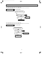
Revision C:
● MUX-A10/A19/A20/A25/A26WV - E1 can be
connected to MSC-A07/A09/A12YV - E1 .
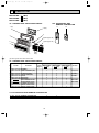
SPLIT-TYPE, AIR CONDITIONERS
SPLIT-TYPE, HEAT PUMP AIR CONDITIONERS
Please void OB307 REVISED EDITION-B.
No. OB307
HFC
REVISED EDITION-C
utilized
SERVICE MANUAL
R410A
Wireless type
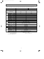
Models
MSC-A07WV
MSC-A09WV
MSC-A12WV
MSC-A07WV
MSC-A09WV
MSC-A12WV
-
E1 (WH)
MSC-A07WV MSC-A09WV MSC-A12WV -
E1 (WH)
E1 (WH)
E1 (WH)
E1 (WH)
E1 (WH)
E1 (WH)
·
·
·
·
·
·
MU-A07WV - E1
MU-A09WV - E1
MU-A12WV - E1
MUH-A07WV MUH-A09WV MUH-A12WV -
·
·
·
·
·
MUX-A10WV
MUX-A19WV
MUX-A20WV
MUX-A25WV
MUX-A26WV
E1
E1
E1
Multi system type
Models
E1 (WH)
E1 (WH)
-
E1
E1
E1
E1
E1
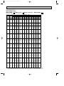
CONTENTS
MSC-A07WV MSC-A09WV MSC-A12WV -
Remote
controller
E1
E1
E1
Indication of
model name
1. TECHNICAL CHANGES ····································2
2. PART NAMES AND FUNCTIONS······················6
3. INDOOR / OUTDOOR
CORRESPONDENCE TABLE ···························8
4. SPECIFICATION·················································9
5. NOISE CRITERIA CURVES ·····························15
6. OUTLINES AND DIMENSIONS ·······················18
7. WIRING DIAGRAM ··········································22
8. REFRIGERANT SYSTEM DIAGRAM ··············28
9. PERFORMANCE CURVES ······························40
10. MICROPROCESSOR CONTROL ····················75
11. SERVICE FUNCTIONS·····································86
12. TROUBLESHOOTING······································88
13. DISASSEMBLY INSTRUCTIONS···················105
14. PARTS LIST····················································116
NOTE:
•As for indoor units MSC-A07/A09/A12YV - E1 , refer to the service manual OB329.
•As for outdoor units MUX-A22WV - E1 , refer to the service manual OB318 REVISED EDITION-A.
•As for outdoor units MXZ-A18/A26/A32WV - E1 , refer to the service manual OB319.
OB307C-1.qxp
04.5.11 1:16 PM
Page 2
Revision C:
•MUX-A10/A19/A20/A25/A26WV -
1
E1
can be connected to MSC-A07/A09/A12YV -
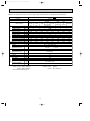
TECHNICAL CHANGES
MSC-07RV- E4 ➔MSC-A07WV- E1
MSC-09RV- E4 ➔MSC-A09WV- E1
MSC-12RV- E4 ➔MSC-A12WV- E1
1. Rated voltage has changed. (220-240V➔230V)
2. Indoor model has changed.
MU-07RV- E4 ➔MU-A07WV- E1
1. Refrigerant has changed. (R22➔R410A)
2. Compressor has changed. (RH130VGCT➔RN092VHSHT)
MU-09RV- E4 ➔MU-A09WV- E1
1. Refrigerant has changed. (R22➔R410A)
2. Compressor has changed. (RH140VGCT➔RN099VHSHT)
MU-12RV- E4 ➔MU-A12WV- E1
1. Refrigerant has changed. (R22➔R410A)
2. Compressor has changed. (RH220VHAT➔RN135VHSHT)
MUH-07RV- E4 ➔MUH-A07WV- E1
1. Refrigerant has changed. (R22➔R410A)
2. Compressor has changed. (RH130VGCT➔RN092VHSHT)
MUH-09RV- E4 ➔MUH-A09WV- E1
1. Refrigerant has changed. (R22➔R410A)
2. Compressor has changed. (RH165VGCT➔RN104VHSHT)
MUH-12RV- E4 ➔MUH-A12WV- E1
1. Refrigerant has changed. (R22➔R410A)
2. Compressor has changed. (RH220VHAT➔RN135VHSHT)
MUX-10RV- E2 ➔MUX-A10WV- E1
1. Outdoor model has changed.
2. Refrigerant has changed. (R22➔R410A)
MUX-19TV- E1 ➔MUX-A19WV- E1
MUX-20TV- E1 ➔MUX-A20WV- E1
MUX-25TV- E1 ➔MUX-A25WV- E1
1. Refrigerant has changed. (R22➔R410A)
MUX-24RV- E2 ➔MUX-A26WV- E1
1. Outdoor model has changed.
2. Refrigerant has changed. (R22➔R410A)
2
E1
.
OB307C-1.qxp
04.5.11 1:16 PM
Page 3
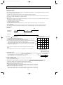
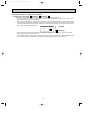
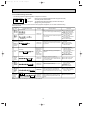
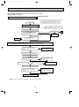
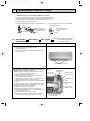
INFORMATION FOR THE AIR CONDITIONER WITH R410A REFRIGERANT
• This room air conditioner adopts an HFC refrigerant (R410A) which never destroys the ozone layer.
• Pay particular attention to the following points, though the basic installation procedure is same as that for R22 conditioners.
1 As R410A has working pressure approximate 1.6 times as high as that of R22, some special tools and piping parts/
materials are required. Refer to the table below.
2 Take sufficient care not to allow water and other contaminations to enter the R410A refrigerant during storage and
installation, since it is more susceptible to contaminations than R22.
3 For refrigerant piping, use clean, pressure-proof parts/materials specifically designed for R410A. (Refer to 2. Refrigerant
piping.)
4 Composition change may occur in R410A since it is a mixed refrigerant. When charging, charge liquid refrigerant to prevent
composition change.
New refrigerant
R410A
R22
Composition (Ratio)
HFC-32: HFC-125 (50%:50%)
R22 (100%)
Refrigerant handling
Pseudo-azeotropic refrigerant
Single refrigerant
Not included
Included
Refrigerant
Chlorine
A1/A1
A1
72.6
86.5
Boiling point (:)
-51.4
-40.8
Steam pressure [25:](Mpa)
1.557
0.94
64
44.4
Non combustible
Non combustible
0
0.055
Refrigerant
Safety group (ASHRAE)
Molecular weight
Saturated steam density [25:](Kg/K)
Combustibility
ODP w1
GWP w2
Refrigerant charge method
1730
1700
From liquid phase in cylinder
Gas phase
Possible
Possible
Kind
Incompatible oil
Compatible oil
Color
Non
Light yellow
Non
Non
oil
Refrigerating
Additional charge on leakage
Smell
w1 :Ozone Destruction Parameter : based on CFC-11
w2 :Global Warmth Parameter
: based on CO2
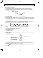
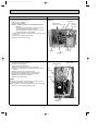
New Specification
Compressor
Previous refrigerant
Current Specification
The incompatible refrigerating oil easily separates from
Since refrigerant and refrigerating oil are compatible each,
refrigerant and is in the upper layer inside the suction muffler. refrigerating oil backs to the compressor through the lower
Raising position of the oil back hole enables to back the
position oil back hole.
refrigerating oil of the upper layer to flow back to the
compressor.
Suction muffler
Suction muffler
Compressor
Oil back hole
Compressor
Refrigerating oil
Oil back hole
Refrigerant
Refrigerating oil /Refrigerant
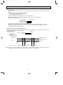
NOTE : The unit of pressure has been changed to MPa on the international system of units(SI unit system).
f [Gauge])
The conversion factor is: 1(MPa [Gauge]) =10.2(kgf/f
3
OB307C-1.qxp
04.5.11 1:16 PM
Page 4
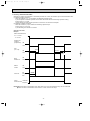
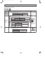
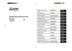
Conversion chart of refrigerant temperature and pressure
(MPa [Gauge])
4.0
Saturated liquid pressure
3.5
R410A
3.0
R22
2.5
2.0
NOTE : The unit of pressure has been changed to MPa on the
international system of units(SI unit system).
1.5
1.0
f [Gauge])
The conversion factor is: 1(MPa [Gauge]) =10.2(kgf/f
0.5
0.0
-0.5
-30 -20 -10
0
10
20
30
40
50
60
(:)
1.Tools dedicated for the air conditioner with R410A refrigerant
The following tools are required for R410A refrigerant. Some R22 tools can be substituted for R410A tools.
The diameter of the service port on the stop valve in outdoor unit has been changed to prevent any other refrigerant being
charged into the unit. Cap size has been changed from 7/16 UNF with 20 threads to 1/2 UNF with 20 threads.
R410A tools
Description
Can R22 tools be used?
R410A has high pressures beyond the measurement range of existing
gauges. Port diameters have been changed to prevent any other refrigerant
from being charged into the unit.
Gauge manifold
No
Charge hose
No
Gas leak detector
No
Hose material and cap size have been changed to improve the pressure
resistance.
Dedicated for HFC refrigerant.
Yes
6.35 mm and 9.52 mm
No
12.7 mm
Flare tool
Yes
Clamp bar hole has been enlarged to reinforce the spring strength in the tool.
Flare gauge
Vacuum pump
adapter
Electronic scale for
refrigerant charging
New
Provided for flaring work (to be used with R22 flare tool).
Provided to prevent the back flow of oil. This adapter enables you to use
vacuum pumps.
It is difficult to measure R410A with a charging cylinder because the
refrigerant bubbles due to high pressure and high-speed vaporization
Torque wrench
New
New
No : Not Substitutable for R410A
Yes : Substitutable for R410A
2.Refrigerant piping
1 Specifications
Use the refrigerant pipes that meet the following specifications.
Pipe
For liquid
For gas
Outside diameter
mm
Wall
thickness
6.35
0.8 mm
9.52
0.8 mm
12.7
0.8 mm
Insulation material
Heat resisting foam plastic
Specific gravity 0.045 Thickness 8 mm
• Use a copper pipe or a copper-alloy seamless pipe with a thickness of 0.8 mm. Never use any pipe with a thickness less
than 0.8mm, as the pressure resistance is insufficient.
4
OB307C-1.qxp
04.5.11 1:16 PM
Page 5
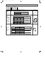
2 Flaring work and flare nut
Flaring work for R410A pipe differs from that for R22 pipe.
For details of flaring work, refer to Installation manual “FLARING WORK”.
Dimension of flare nut
Pipe diameter
mm
R410A
R22
6.35
17
17
9.52
22
22
12.7
26
24
3.Refrigerant oil
Apply the special refrigeration oil (accessories: packed with indoor unit) to the flare and the union seat surfaces.
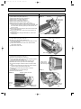
4.Air purge
• Do not discharge the refrigerant into the atmosphere.
Take care not to discharge refrigerant into the atmosphere during installation, reinstallation, or repairs to the refrigerant
circuit.
• Use the vacuum pump for air purging for the purpose of environmental protection.
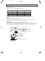
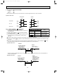
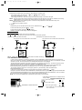
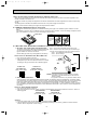
5.Additional charge
For additional charging, charge the refrigerant from liquid phase of the gas cylinder.
If the refrigerant is charged from the gas phase, composition change may occur in the refrigerant inside the cylinder and the
outdoor unit. In this case, ability of the refrigerating cycle decreases or normal operation can be impossible. However,
charging the liquid refrigerant all at once may cause the compressor to be locked. Thus, charge the refrigerant slowly.
Union
Stop valve
Indoor unit
Liquid pipe
Outdoor unit
Gas pipe
Refrigerant gas
cylinder
operating valve
Service port
Gauge manifold
valve (for R410A)
Charge hose (for R410A)
Refrigerant gas cylinder
for R410A with siphon
Refrigerant (liquid)
Electronic scale for refrigerant charging
5
OB307C-1.qxp
2
04.5.11 1:16 PM
Page 6
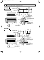
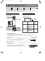
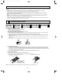
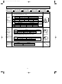
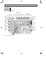
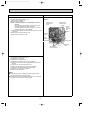
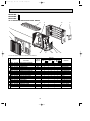
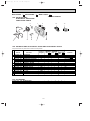
PART NAMES AND FUNCTIONS
INDOOR UNIT
MSC-A07WV - E1
MSC-A09WV - E1
MSC-A12WV - E1
Front panel
Air cleaning filter
(White bellows type)
Air inlet
Deodorizing filter
(Gray sponge type)
to Breaker
Power supply cord
Panel
Air filter
Remote control
receiving section
Air outlet
Vertical vane
Horizontal vane
Remote controller
Operation section
Display section
(When the front panel is opened)
Operation indicator lamp
Emergency operation switch
Receiving section
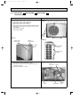
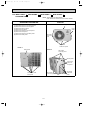
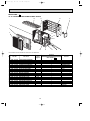
OUTDOOR UNIT
MU-A07WV - E1
MU-A09WV - E1
MU-A12WV - E1
MUH-A07WV - E1
MUH-A09WV - E1
MUH-A12WV - E1
MUX-A10WV- E1
Air inlet
(back and side)
Air inlet
(back and side)
Piping
Piping
Drain hose
Drain hose
Air outlet
Air outlet
Drain outlet
Drain outlet
6
OB307C-1.qxp
04.5.11 1:16 PM
Page 7
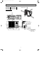
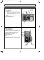
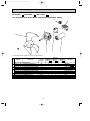
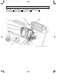
OUTDOOR UNIT
MUX-A19WV- E1 MUX-A25WV- E1
MUX-A20WV- E1
MUX-A26WV- E1
Air inlet
(Back and side)
Air inlet
(Back and side)
Air outlet
Air outlet
Piping
Piping
Drainage hose
Drainage hose
Drain outlet
Drain outlet
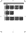
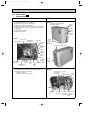
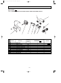
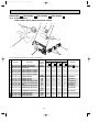
ACCESSORIES
MUH-A07WV- E1
MUH-A09WV- E1
MUH-A12WV- E1
MSC-A07WV- E1
MSC-A09WV- E1
MSC-A12WV- E1
<Outdoor unit: MUH type>
<Indoor unit>
1 Installation plate
1
1 Drain socket
1
2 Installation plate fixing screw 4 o 25 mm
5
2 Drain cap
2
3 Remote controller holder
1
4 Fixing screw for 3 3.5 o 16 mm
2
5 Battery (AAA) for remote controller
2
6 Wireless remote controller
1
7 Felt tape (Used for left or left-rear piping)
1
8 Deodorizing filter
1
9 Air cleaning filter
1
0 Refrigerant oil
1
7
OB307C-1.qxp
04.5.11 1:16 PM
Page 8
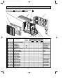
REMOTE CONTROLLER
MSC-A07WV - E1
MSC-A09WV - E1
MSC-A12WV - E1
Signal transmitting section
Operation display section
PM
AM
OPERATE /STOP
(ON /OFF)button
TOO
ON/OFF WARM
TOO
COOL
TEMPERATURE buttons
Open the front lid.
CLOCK
PM
AM
TOO
ON/OFF WARM
FAN SPEED CONTROL button
TOO
COOL
FAN
STOP
VANE
START
OFF-TIMER button
ON-TIMER button
HR. button
MIN. button
(TIME SET button)
I FEEL COOL
HEAT
/FAN
DRY
/
HR.
MODE
OPERATION SELECT button
ECONO COOL
ECONO COOL button
MIN.
RESET CLOCK
CLOCK SET button
VANE CONTROL button
RESET button
3
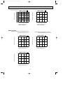
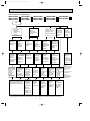
INDOOR / OUTDOOR CORRESPONDENCE TABLE
MSC-A07WV - E1
MUX-A10WV - E1
MSC-A09WV - E1
MUX-A19WV - E1
MSC-A12WV - E1
MUX-A20WV - E1
MUX-A25WV - E1
MUX-A26WV - E1
OUTDOOR UNIT
MUX-A10WV-
Combination of
the connectable
indoor units
A:
B:
E1
MUX-A19WV-
A: MSC-A12WVor
MSC-A07WV- E1
MSC-A12YVor
MSC-A07YV- E1 B: MSC-A07WVor
MSC-A07YV-
E1
MUX-A20WV-
E1
E1
E1
A:
B:
C:
E1
8
E1
MUX-A25WV-
E1
MUX-A26WV-
E1
A: MSC-A12WV- E1
or
MSC-A09WV- E1 A: MSC-A12WV- E1
B: MSC-A12YV- E1
or
or
MSC-A09YV- E1 B: MSC-A12YV- E1 C: MSC-A09WV- E1
or
D: MSC-A09YV- E1
OB307C-1.qxp
04.5.11 1:16 PM
4
Page 9
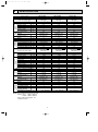
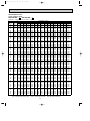
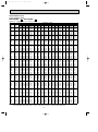
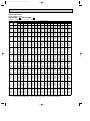
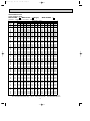
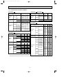
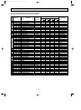
SPECIFICATION
Indoor model
Function
Indoor unit power supply
Special
remarks
Fan
motor
Electrical
data
Capacity Air flow(High/Med.w/Low w )
Power outlet
Running current
Power input
Power factor
Starting current
Fan motor current
Model
Winding
resistance(at 20:)
Dimensions WOHOD
Weight
Air direction
Sound level(High/Med.w/Loww )
Fan speed (High/Med.w/Low w)
Fan speed regulator
Thermistor RT11(at 25:)
Thermistor RT12(at 25:)
Outdoor model
K /h
A
A
W
%
A
A
"
mm
kg
dB
rpm
k"
k"
kW
Capacity
R/h
Dehumidification
K /h
Outdoor air flow
A
Power outlet
A
Running current
W
Power input
A(kW)
Auxiliary heater
%
Power factor
A
Starting current
A
Compressor motor current
A
Fan motor current
Coefficient of performance(C.O.P)
Model
W
Output
Winding
"
resistance(at 20:)
Model
Winding
"
resistance(at 20:)
mm
Dimensions WOHOD
kg
Weight
dB
Sound level
rpm
Fan speed
Fan speed regulator
Refrigerant filling
kg
capacity (R410A)
cc
Refrigerating oil (Model)
Special
remarks
Fan
motor Compressor
Electrical
data
Capacity
Outdoor unit power supply
MSC-A07WV - E1
Cooling
Single phase
230V,50Hz
474/372w/276w
10
0.17
35
90
—
0.17
RC4V19-LA
WHT-BLK 413
BLK-RED 334
815O278O217
9
5
36/31w/25 w
900/750w/600w
3
10
10
MU-A07WV - E1
Single phase
230V,50Hz
2.3
0.9
1,686
10
2.98
675
—
98
23
2.76
0.22
3.24
RN092VHSHT
600
C-R 3.87
C-S 6.14
RA6V23-FC
WHT-BLK 353
BLK-RED 321
780o540o255
34
45
735
1
MSC-A09WV - E1
Cooling
Single phase
230V,50Hz
474/384w/306w
10
0.17
35
90
—
0.17
RC4V19-LA
WHT-BLK 413
BLK-RED 334
815O278O217
9
5
36/31w/25 w
900/770w/650 w
3
10
10
MU-A09WV - E1
Single phase
230V,50Hz
2.55
1.1
1,686
10
3.26
745
—
99
24
3.04
0.22
3.27
RN099VHSHT
700
C-R 3.40
C-S 4.56
RA6V23-FC
WHT-BLK 353
BLK-RED 321
780o540o255
34
45
735
1
MSC-A12WV - E1
Cooling
Single phase
230V,50Hz
582/444w/324w
10
0.19
40
92
—
0.19
RC4V19-KA
WHT-BLK 316
BLK-RED 299
815O278O217
10
5
40/33w/26 w
930/760w/600w
3
10
10
MU-A12WV - E1
Single phase
230V,50Hz
3.45
1.6
1,914
10
4.91
1,100
—
97
29
4.60
0.31
3.03
RN135VHSHT
900
C-R 2.79
C-S 3.36
RA6V33-DC
WHT-BLK 301
BLK-RED 332
780o540o255
36
49
825
1
0.75
0.80
0.83
350 (NEO22 )
NOTE: Test conditions are based on ISO 5151.
Cooling : Indoor DB27°C WB19°C
Outdoor DB35°C WB24°C
Indoor-Outdoor piping length : 5m
w Reference value
9
350 (NEO22 )
620 (NEO22)
OB307C-1.qxp
04.5.11 1:16 PM
Page 10
Indoor model
Function
Indoor unit power supply
Special
remarks
Fan
motor
Electrical
data
Capacity Air flow(High/Med.w/Low w)
Power outlet
Running current
Power input
Power factor
Starting current
Fan motor current
Model
Winding
resistance(at 20:)
Dimensions WOHOD
Weight
Air direction
Sound level(High/Med.w/Loww )
Fan speed(High/Med.w/Loww )
Fan speed regulator
Thermistor RT11(at 25:)
Thermistor RT12(at 25:)
Outdoor model
K /h
A
A
W
%
A
A
"
mm
kg
dB
rpm
k"
k"
Outdoor unit power supply
Special
remarks
Fan
Compressor
motor
Electrical
data
Capacity
Capacity
kW
Dehumidification
R/h
Outdoor air flow
K /h
Power outlet
A
Running current
A
Power input
W
Auxiliary heater
A(kW)
Power factor
%
Starting current
A
Compressor motor current
A
Fan motor current
A
Coefficient of performance (C.O.P)
Model
Output
W
Winding
"
resistance (at 20:)
Model
Winding
"
resistance (at 20:)
Dimensions WOHOD
mm
Weight
kg
Sound level
dB
Fan speed
rpm
Fan speed regulator
Refrigerant filling
kg
capacity (R410A)
Refrigerating oil (Model)
cc
Thermistor RT61 (at 0:)
k"
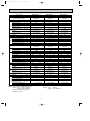
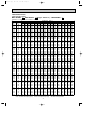
MSC-A09WV - E1
MSC-A12WV - E1
MSC-A07WV - E1
Heating
Heating
Heating
Cooling
Cooling
Cooling
Single phase
Single phase
Single phase
230V,50Hz
230V,50Hz
230V,50Hz
474/372 w/276 w 510/420 w /342w 474/384 w/306w 588/456 w/342w 582/444 w/324w 606/498 w/396w
10
10
10
0.17
0.17
0.19
35
35
40
90
90
92
—
—
—
0.17
0.17
0.19
RC4V19-LA
RC4V19-LA
RC4V19-KA
WHT-BLK 413
WHT-BLK 413
WHT-BLK 316
BLK-RED 334
BLK-RED 334
BLK-RED 299
815O278O217
815O278O217
815O278O217
9
9
10
5
5
5
36/31w /25 w 36/31 w /25 w
36/31w /25 w
39/32w/25 w
40/33w/26 w
39/33w/26w
900/750w/600 w 950/820 w /700 w 900/770w/650w 1,050/870w/700w 930/760w/600w 960/830w/700 w
3
3
3
10
10
10
10
10
10
MUH-A07WV - E1
MUH-A09WV - E1
MUH-A12WV - E1
Single phase
Single phase
Single phase
230V,50Hz
230V,50Hz
230V,50Hz
3.4
3.9
2.3
2.55
3.05
2.5
1.6
—
0.9
1.1
—
—
1,686
1,710
1,710
10
10
10
4.51
4.61
2.98
3.26
3.52
2.86
1,020
1,040
675
745
805
655
—
—
—
98
98
98
99
99
100
23
24
29
4.20
4.30
2.76
2.95
3.21
2.64
0.22
0.31
0.31
3.21
3.61
3.24
3.27
3.69
3.62
RN092VHSHT
RN104VHSHT
RN135VHSHT
600
700
900
C-R 3.87
C-R 3.40
C-R 2.79
C-S 6.14
C-S 4.56
C-S 3.36
RA6V23-FB
RA6V33-DB
RA6V33-DB
WHT-BLK 353
WHT-BLK 301
WHT-BLK 301
BLK-RED 321
BLK-RED 332
BLK-RED 332
780o540o255
780o540o255
780o540o255
35
38
40
47
49
49
735
825
825
1
1
1
0.75
350 (NEO22)
33.18
NOTE: Test conditions are based on ISO 5151.
Cooling : Indoor DB27°C WB19°C
Outdoor DB35°C WB24°C
Indoor-Outdoor piping length : 5m
w Reference value
1.10
1.15
350 (NEO22)
33.18
620 (NEO22)
33.18
Heating : Indoor
Outdoor
10
DB20°C
DB 7°C/WB 6°C
OB307C-1.qxp
04.5.11 1:16 PM
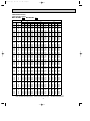
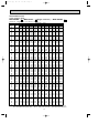
Page 11
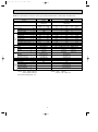
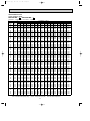
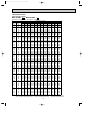
NOTE: As for specification of indoor unit, refer to page 9 (MSC-A07/A09/A12WV) or OB329 (MSC-A07/A09/A12YV).
Outdoor model
Function
Outdoor unit power supply
Special
remarks
Fan
motor
Compressor
Capacity
Dehumidification
Outdoor air flow
Power outlet
Running current
Power input
Auxiliary heater
Power factor
Starting current
Compressor motor current
Fan motor current
kW
R/h
K /h
A
A
W
A(kW)
%
A
A
A
Coefficient of performance (C.O.P)
Model
Output
W
Winding
"
resistance (at 20:)
Model
Winding
"
resistance (at 20:)
Dimensions WOHOD
mm
Weight
kg
Sound level
dB
Fan speed
rpm
Fan speed regulator
Refrigerant filling
kg
capacity (R410A)
Refrigerating oil (Model)
cc
Electrical
data
Capacity
Indoor unit No.
MUX-A10WV Cooling
Single phase
230V,50Hz
Double
A+B
1.4O2
0.2O2
Single
A or B
2.4
0.9
1,914
10
3.25
730
3.20
725
—
97.7
98.5
21
2.96
2.91
MUX-A19WV Cooling
Single phase
230V,50Hz
E1
0.29
3.50
3.16
RN092VHSHT
600
C-R 3.87
C-S 6.14
RA6V33-FC
WHT-BLK 223
BLK-RED 221
780O540O255
35
49
825
1
0.90 (Room A+B)
350 (NEO22)
NOTE: Test conditions are based on ISO 5151.
Cooling : Indoor DB27°C WB19°C
Outdoor DB35°C WB24°C
Indoor-Outdoor piping length : 5m
Double
Single
A+B
B
3.5+2.4
2.4
1.4+0.9
0.9
2,460
20
8.96
5.73
3.51
2,005
1,280
785
—
97.2
97.3
97.1
48
2.94
8.39
5.16
0.57
2.93
2.84
2.65
MC1 : RN145VHSHT, MC2 : RN092VHSHT
MC1 : 1,000, MC2 : 600
C-R 2.43
C-R 3.87
MC1 :
, MC2 :
C-S 3.80
C-S 6.14
RA6V60-GA
Single
A
3.5
1.4
WHT-BLK 90
BLK-RED 146
840O640O330
66
52
730
1
1.00 (Room A)
0.80 (Room B)
MC1 : 620 (NEO22), MC2 : 350 (NEO22)
Heating : Indoor
Outdoor
11
E1
DB20°C
DB 7°C/WB 6°C
OB307C-1.qxp
04.5.11 1:16 PM
Page 12
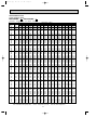
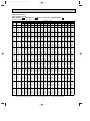
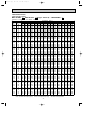
NOTE: As for specification of indoor unit, refer to page 9 (MSC-A07/A09/A12WV) or OB329 (MSC-A07/A09/A12YV).
Outdoor model
Function
MUX-A20WV Cooling
Single phase
230V,50Hz
Outdoor unit power supply
Single
A
2.6
0.9
Special
remarks
Fan
motor
Compressor
Capacity
Dehumidification
Outdoor air flow
Power outlet
Running current
Power input
Auxiliary heater
Power factor
Starting current
Compressor motor current
Fan motor current
kW
R/h
K /h
A
A
W
A(kW)
%
A
A
A
Coefficient of performance (C.O.P)
Model
Output
W
Winding
"
resistance (at 20:)
Model
Winding
"
resistance (at 20:)
Dimensions WOHOD
mm
Weight
kg
Sound level
dB
Fan speed
rpm
Fan speed regulator
Refrigerant filling
kg
capacity (R410A)
Refrigerating oil (Model)
cc
Electrical
data
Capacity
Indoor unit No.
3.64
815
97.3
3.07
3.06
E1
Double
Double
A+B or A+C
B+C
2.6+2.8
1.75O2
0.9+1.1
0.3O2
2,460
20
8.18
4.86
4.86
1,850
1,090
1,075
—
98.3
97.5
96.2
47
4.29
4.29
7.61
0.57
3.02
2.61
2.81
MC1 : RN099VHSHT, MC2 : RN125VHSHT
MC1 : 650, MC2 : 800
C-R 3.40
C-R 2.86
MC1 :
, MC2 :
C-S 4.56
C-S 5.72
RA6V60-GA
Single
B or C
2.9
1.2
WHT-BLK 90
BLK-RED 146
840O640O330
65
52
730
1
0.80 (Room A)
1.00 (Room B+C)
MC1 : 350 (NEO22), MC2 : 350 (NEO22)
NOTE: Test conditions are based on ISO 5151.
Cooling : Indoor DB27°C WB19°C
Outdoor DB35°C WB24°C
Indoor-Outdoor piping length : 5m
Heating : Indoor
Outdoor
12
DB20°C
DB 7°C/WB 6°C
Triple
A+B+C
2.5+1.75O2
0.8+0.3O2
8.41
1,885
97.5
7.84
3.02
OB307C-1.qxp
04.5.11 1:16 PM
Page 13
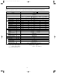
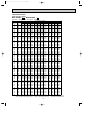
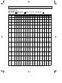
NOTE: As for specification of indoor unit, refer to page 9 (MSC-A07/A09/A12WV) or OB329 (MSC-A07/A09/A12YV).
Outdoor model
Function
Outdoor unit power supply
Capacity
kW
Dehumidification
R/h
Outdoor air flow
K /h
Power outlet
A
Running current
A
Power input
W
Auxiliary heater
A(kW)
Power factor
%
Starting current
A
Compressor motor current
A
Fan motor current
A
Coefficient of performance (C.O.P)
Model
Output
W
Winding
"
resistance (at 20:)
Model
Winding
"
resistance (at 20:)
Dimensions WOHOD
mm
Weight
kg
Sound level
dB
Fan speed
rpm
Fan speed regulator
Refrigerant filling
kg
capacity (R410A)
Refrigerating oil (Model) cc
Special
remarks
Fan
motor
Compressor
Electrical
data
Capacity
Indoor unit No.
MUX-A25WV - E1
Cooling
Single phase 230V,50Hz
Single
A or B
Double
A+B
3.5
1.4
3.5O2
1.4O2
2,460
20
5.88
1,300
11.49
2,540
—
96.1
96.1
54
5.31
10.92
0.57
2.61
2.67
MC1 : RN145VHSHT, MC2 : RN145VHSHT
MC1 : 1,000, MC2 : 1,000
C-R 2.43
C-R 2.43
MC1 :
, MC2 :
C-S 3.80
C-S 3.80
RA6V60-GA
WHT-BLK 90
BLK-RED 146
840O640O330
68
52
730
1
0.95 (Room A)
0.95 (Room B)
MC1 : 620 (NEO22), MC2 : 620 (NEO22)
NOTE: Test conditions are based on ISO 5151.
Cooling : Indoor DB27°C WB19°C
Outdoor DB35°C WB24°C
Indoor-Outdoor piping length : 5m
Heating : Indoor
Outdoor
13
DB20°C
DB 7°C/WB 6°C
OB307C-1.qxp
04.5.11 1:16 PM
Page 14
NOTE: As for specification of indoor unit, refer to page 9 (MSC-A07/A09/A12WV) or OB329 (MSC-A07/A09/A12YV).
Outdoor model
Function
Outdoor unit power supply
Capacity
kW
Dehumidification
R/h
Outdoor air flow
K /h
Power outlet
A
Running current
A
Power input
W
Auxiliary heater
A(kW)
Power factor
%
Starting current
A
Compressor motor current
A
Fan motor current
A
Coefficient of performance (C.O.P)
Model
Output
W
Winding
"
resistance (at 20:)
Model
Winding
"
resistance (at 20:)
Dimensions WOHOD
mm
Weight
kg
Sound level
dB
Fan speed
rpm
Fan speed regulator
Refrigerant filling
kg
capacity (R410A)
Refrigerating oil (Model) cc
Single
C or D
3.4
1.2
2.75
1.1
5.28
1,180
4.54
1,015
97.2
97.2
4.75
4.01
2.79
2.62
Special
remarks
Fan
motor
Compressor
Electrical
data
Capacity
Indoor unit No.
Single
A or B
MUX-A26WV - E1
Cooling
Single phase 230V,50Hz
Double
Triple
Double A+C or A+D Double
A+B+C
or
or
C+D
A+B
B+C or B+D
A+B+D
3.4+2.7
1.7O2 1.95O2+2.8
1.95O2
1.2+1.1
0.2O2+1.1
0.3O2
0.2O2
2,760
20
9.57
9.61
4.78
5.46
2,095
2,105
1,060
1,210
—
95.2
95.2
96.4
96.4
52
9.04
9.08
4.25
4.93
0.53
2.81
3.02
3.01
3.02
MC1 : RN145VHSHT, MC2 : RN125VHSHT
MC1 : 1,000, MC2 : 800
Triple
Four
A+C+D
or
A+B+C+D
B+C+D
3.4+1.7O2 1.95O2+1.7O2
1.2+0.3O2 0.2O2+0.3O2
C-R 2.43
C-R 2.86
, MC2 :
C-S 3.80
C-S 5.72
RA6V60-FA
WHT-BLK 79
BLK-RED 80
840O850O330
76
52
730
1
1.05 (Room A+B)
1.05 (Room C+D)
MC1 : 620 (NEO22), MC2 : 350 (NEO22)
MC1 :
NOTE: Test conditions are based on ISO 5151.
Cooling : Indoor DB27°C WB19°C
Outdoor DB35°C WB24°C
Indoor-Outdoor piping length : 5m
Heating : Indoor
Outdoor
14
DB20°C
DB 7°C/WB 6°C
9.66
2,140
9.75
2,210
96.3
98.6
9.13
9.22
3.02
3.09
04.5.11 1:16 PM
5
Page 15
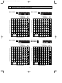
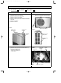
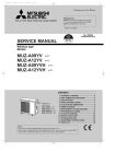
NOISE CRITERIA CURVES
MSC-A07WV-
E1
FAN SPEED FUNCTION
High
COOL
SPL(dB(A))
MSC-A09WV-
LINE
E1
FAN SPEED FUNCTION
High
36
HEAT
90
90
80
80
70
NC-70
60
NC-60
50
NC-50
40
NC-40
30
NC-30
20
APPROXIMATE
TERESHOLD OF
HEARING FOR
CONTINUOUS
NOISE
36
HEAT
39
LINE
WB19:
WB -:
70
NC-70
60
NC-60
50
NC-50
40
NC-40
30
NC-30
20
NC-20
APPROXIMATE
TERESHOLD OF
HEARING FOR
CONTINUOUS
NOISE
NC-20
10
10
63
125
250
500
1000
2000
4000
63
8000
125
MSC-A12WV-
E1
FAN SPEED FUNCTION
COOL
High
HEAT
250
500
1000
2000
4000
8000
LINE
BAND CENTER FREQUENCIES, Hz
BAND CENTER FREQUENCIES, Hz
SPL(dB(A))
MU-A07WVMU-A09WV-
LINE
40
39
Test conditions,
Cooling : DB27:
80
80
OCTAVE BAND SOUND PRESSURE LEVEL, dB re 0.0002 MICRO BAR
90
70
NC-70
60
NC-60
50
NC-50
40
NC-40
30
NC-30
APPROXIMATE
TERESHOLD OF
HEARING FOR
CONTINUOUS
NOISE
E1
FUNCTION
SPL(dB(A))
E1
COOL
45
Test conditions,
Cooling : DB27:
WB19:
90
20
SPL(dB(A))
COOL
Test conditions.
Cooling : DB27:
Heating : DB20:
WB19:
WB -:
OCTAVE BAND SOUND PRESSURE LEVEL, dB re 0.0002 MICRO BAR
OCTAVE BAND SOUND PRESSURE LEVEL, dB re 0.0002 MICRO BAR
Test conditions,
Cooling : DB27:
Heating : DB20:
OCTAVE BAND SOUND PRESSURE LEVEL, dB re 0.0002 MICRO BAR
OB307C-1.qxp
70
NC-70
60
NC-60
50
NC-50
40
NC-40
30
NC-30
20
NC-20
10
WB19:
APPROXIMATE
TERESHOLD OF
HEARING FOR
CONTINUOUS
NOISE
NC-20
10
63
125
250
500
1000
2000
4000
8000
63
BAND CENTER FREQUENCIES, Hz
125
250
500
1000
2000
BAND CENTER FREQUENCIES, Hz
15
4000
8000
OB307C-1.qxp
04.5.11 1:16 PM
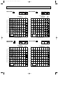
MU-A12WV-
Page 16
E1
FUNCTION
SPL(dB(A))
COOL
49
MUH-A07WV-
LINE
E1
FUNCTION
HEAT
Test conditions,
Cooling :DB35:
90
80
70
NC-70
60
NC-60
50
NC-50
40
NC-40
30
NC-30
20
APPROXIMATE
TERESHOLD OF
HEARING FOR
CONTINUOUS
NOISE
125
70
NC-70
60
NC-60
50
NC-50
40
NC-40
30
NC-30
20
250
500
1000
2000
4000
APPROXIMATE
TERESHOLD OF
HEARING FOR
CONTINUOUS
NOISE
E1
COOL
E1
63
125
SPL(dB(A))
MUX-A10WV-
LINE
500
1000
2000
4000
8000
E1
FUNCTION
SPL(dB(A))
COOL
49
49
LINE
HEAT
WB24:
WB 6:
OCTAVE BAND SOUND PRESSURE LEVEL, dB re 0.0002 MICRO BAR
70
NC-70
60
NC-60
50
NC-50
40
NC-40
30
NC-30
APPROXIMATE
TERESHOLD OF
HEARING FOR
CONTINUOUS
NOISE
Test conditions.
Cooling : DB27:
90
80
20
250
BAND CENTER FREQUENCIES, Hz
Test conditions,
Cooling :DB35:
Heating :DB 7:
90
OCTAVE BAND SOUND PRESSURE LEVEL, dB re 0.0002 MICRO BAR
FUNCTION
NC-20
10
8000
BAND CENTER FREQUENCIES, Hz
MUH-A09WVMUH-A12WV-
WB24:
WB 6:
80
NC-20
10
63
LINE
47
Test conditions,
Cooling :DB35:
Heating :DB 7:
WB24:
OCTAVE BAND SOUND PRESSURE LEVEL, dB re 0.0002 MICRO BAR
OCTAVE BAND SOUND PRESSURE LEVEL, dB re 0.0002 MICRO BAR
90
SPL(dB(A))
COOL
WB19:
80
70
NC-70
60
NC-60
50
NC-50
40
NC-40
30
NC-30
20
NC-20
APPROXIMATE
TERESHOLD OF
HEARING FOR
CONTINUOUS
NOISE
NC-20
10
10
63
125
250
500
1000
2000
4000
63
8000
125
250
500
1000
2000
BAND CENTER FREQUENCIES, Hz
BAND CENTER FREQUENCIES, Hz
16
4000
8000
04.5.11 1:16 PM
Page 17
MUX-A19WV - E1
MUX-A20WV - E1
MUX-A25WV - E1
FUNCTION
SPL(dB(A))
COOL
52
Test conditions.
Cooling :DB35:
90
MUX-A26WV - E1
LINE
WB24:
80
70
NC-70
60
NC-60
50
NC-50
40
NC-40
30
NC-30
20
APPROXIMATE
TERESHOLD OF
HEARING FOR
CONTINUOUS
NOISE
SPL(dB(A))
COOL
52
LINE
WB24:
80
70
NC-70
60
NC-60
50
NC-50
40
NC-40
30
NC-30
20
NC-20
10
FUNCTION
Test conditions.
Cooling :DB35:
90
OCTAVE BAND SOUND PRESSURE LEVEL, dB re 0.0002 MICRO BAR
OCTAVE BAND SOUND PRESSURE LEVEL, dB re 0.0002 MICRO BAR
OB307C-1.qxp
APPROXIMATE
TERESHOLD OF
HEARING FOR
CONTINUOUS
NOISE
NC-20
10
63
125
250
500
1000
2000
4000
8000
63
BAND CENTER FREQUENCIES, Hz
125
250
500
1000
2000
BAND CENTER FREQUENCIES, Hz
17
4000
8000
OB307C-1.qxp
04.5.11 1:16 PM
6
Page 18
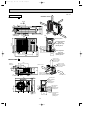
OUTLINES AND DIMENSIONS
Unit: mm
81.5
4.5
133.5
231.5
Installation plate
INDOOR UNIT
Indoor unit
271
MSC-A07WV - E1
MSC-A09WV - E1
81.5
326
42
41
2.5
783
81.5
326
Wall hole [65
215
Air in
149
606
58
{
90
30
60
5 Installation plate
7 or more
278
815
162
Power supply cord
Lead to right 1.0m
Lead to left 0.3m
Drain hose [16
(Connected part O,D)
Insulation [28
110
Air out
19
Liquid line [6.35-0.5m
Gas line [9.52-0.43m
Insulation [37 O.D
[21 I.D
217
MSC-A12WV - E1
161.5
161.5
INDOOR UNIT
17.5
Wireless remote controller
Indoor unit
258
218.5
Installation plate
41
2.5
42
783
81.5
326
81.5
326
Wall hole [65
215
606
162
58
149
Air out
19
Power supply cord
Lead to right 1.0m
Lead to left 0.3m
Wireless remote controller
18
Installation plate
{
90
110
30
Air in
60
5
7 or more
278
815
217
Liquid line [6.35-0.5m
Gas line [9.52-0.43m
Insulation [37 O.D
[21 I.D
Drain hose [16
(Connected part O,D)
Insulation [28
OB307C-1.qxp
04.5.11 1:16 PM
Page 19
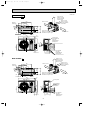
MU-A07WV - E1
MU-A09WV - E1
MU-A12WV - E1
MUH-A07WV - E1
MUH-A09WV - E1
MUH-A12WV - E1
100mm or more
Unit: mm
REQUIRED SPACE
OUTDOOR UNIT
100
mm
ore
m
00m
or m
1
or m
ore
Air in
320
32
ore
or m
35
0m
255
285
320
109
mm
400
m
or
mo
re
Air in
Drainage
3holes [33
147
110
Air out
25
Service panel
10
155
90
260
43- 35-
540
Liquid refrigerant
pipe joint
Refrigerant pipe
(flared) [6.35
40
122
500
780
104
74
19
Gas refrigerant
pipe joint
Refrigerant pipe
(flared) [9.52 (MU-A07/A09WV)
(MUH-A07/A09WV)
[12.7 (MU-A12WV)
(MUH-A12WV)
OB307C-1.qxp
04.5.11 1:16 PM
Page 20
Unit: mm
100mm or more
OUTDOOR UNIT
REQUIRED SPACE
MUX-A10WV- E1
Air in
ore
m
00m
1
100
mm
320
or m
or m
255
285
320
109
32
ore
ore
rm
Air in
o
0mm
40
Drainage
3holes [33
147
35
110
Air out
0m
m
25
or
mo
re
Service panel
10
122
500
780
40
10-
226
176
126
76
260
540
Liquid refrigerant
pipe joint
Refrigerant pipe
(flared) [6.35
120
56
MUX-A19WV- E1
Gas refrigerant
pipe joint
Refrigerant pipe
(flared) [9.52
Open as a rule
500mm or more if
the front and both
sides are open
500
273
438
Air in
100mm or more
200mm or more if
there are obstacles
to both sides
100mm or more
Air in
100
360
330
34
Open as a rule
500mm or more if the back,
both sides and top are open
40
Air out
840
121
61
350mm or more
Service panel
65
80
264
20
76 50 5050
} B UNIT
} A UNIT
320
10 °
640
Liquid refrigerant
pipe joint
Refrigerant pipe
(flared) {6.35
10°
125
30
Drainage
3holes {33
Gas refrigerant
pipe joint
Refrigerant pipe
(flared) {9.52
Gas refrigerant
pipe joint
Refrigerant pipe
(flared) {12.7
OB307C-1.qxp
04.5.11 1:16 PM
Page 21
Unit: mm
OUTDOOR UNIT
MUX-A20WV- E1
Open as a rule
500mm or more if
the front and both
sides are open
500
273
438
Air in
Air in
360
330
34
125
30
Drainage
3holes {33
100mm or more
200mm or more if
there are obstacles
to both sides
100mm or more
Open as a rule
500mm or more if the back,
both sides and top are open
100
350mm or more
40
Air out
} C UNIT
} B UNIT
} A UNIT
76 50 505050 50
10°
Service panel
Liquid refrigerant
pipe joint
Refrigerant pipe
(flared) {6.35
320
10°
61
640
840
121
Gas refrigerant
pipe joint
Refrigerant pipe
(flared) {9.52
65
264
Open as a rule
500mm or more if
the front and both
sides are open
MUX-A25WV- E1
500
273
100mm or more
200mm or more if
there are obstacles
to both sides
100mm or more
438
Air in
Air in
360
330
34
Open as a rule
500mm or more if the back,
both sides and top are open
100
350mm or more
40
Air out
840
121
61
} B UNIT
} A UNIT
264
80
21
76 50 5050
Liquid refrigerant
pipe joint
Refrigerant pipe
(flared) {6.35
320
10°
640
Service panel
10°
125
30
Drainage
3holes {33
Gas refrigerant
pipe joint
Refrigerant pipe
(flared) {12.7
OB307C-1.qxp
04.5.11 1:16 PM
Page 22
Open as a rule
500mm or more if
the front and both
sides are open
OUTDOOR UNIT
MUX-A26WV- E1
100mm or more
360
330
125
34
100mm or more
200mm or more if
there are obstacles
to both sides
40
30
438
273
Air in
100
Drainage
3 holes
{33
Unit: mm
Air in
Air out 500
840
121
65
61
Open as a rule
500mm or more if the back,
both sides and top are open
350mm or more
Service panel
C Unit
B Unit
A Unit
Gas refrigerant
pipe joint
Refrigerant pipe
(flared) {12.7
76 50 50 50 50 50 50 50
430
10°
D Unit
Gas refrigerant
pipe joint
Refrigerant pipe
(flared) {9.52
80
7
10°
850
Liquid refrigerant
pipe joint
Refrigerant pipe
(flared) {6.35
260
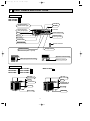
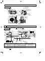
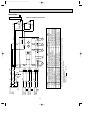
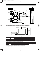
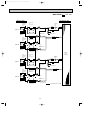
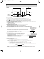
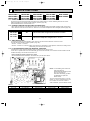
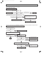
WIRING DIAGRAM
MSC-A07WV - E1
MSC-A09WV - E1 MSC-A12WV - E1
MODELS WIRING DIAGRAM
INDOOR UNIT
TO OUTDOOR
TB
UNIT
L
CONNECTING
BRN
FOR
3
MUH OR
MXZ TYPE
N
12V
FOR
MU OR
MUX TYPE
12V
2
BRN
TAB12
RED
CN201
3
2
1
CN202
2
1
BLU
BLU
WHT
1
BLK
GRN
CIRCUIT BREAKER
SYMBOL
GRN/YLW
PE
NAME
NR11
RT12
CN
111
RT11
CN
121
C11
F11
SR141
BLK
GRY
YLW
BRN
WHT
RED
3
1
3
5
CN211
CN
101
CN
LD103 151
POWER
SUPPLY
CORD
~/N 230V
50Hz
T11
CN
112
ELECTRONIC CONTROL P.C. BOARD
5
MV
5
POWER MONITOR,
RECEIVER
P.C.BOARD
REMOTE
CONTROLLER
NAME
SYMBOL
SYMBOL
NAME
C11
INDOOR FAN CAPACITOR
NR11
VARISTOR
TB
TERMINAL BLOCK
F11
FUSE(3.15A)
RT11
ROOM TEMPERATURE THERMISTOR
T11
TRANSFORMER
MF
INDOOR FAN MOTOR (INNER FUSE)
RT12
INDOOR COIL THERMISTOR
MV
VANE MOTOR
SR141
SOLID STATE RELAY
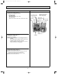
NOTE:1. About the outdoor side electric wiring refer to the outdoor unit electric wiring diagram for servicing.
2. Use copper conductors only. (For field wiring)
3. Symbols below indicate.
/: Terminal block,
: Connector
22
1
2
3
MF
4
5
6
OB307C-1.qxp
04.5.11 1:16 PM
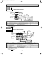
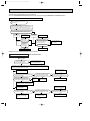
MU-A07WV
MU-A09WV
MU-A12WV
OUTDOOR
Page 23
- E1
- E1
- E1
UNIT
MODELS WIRING DIAGRAM
TB2
2
WHT
FROM
INDOOR UNIT
CONNECTING
12V
1
52C
BLK
DSAR
BRN
CIRCUIT BREAKER TB1
L
52C
WHT
BRN
NO COM
N
POWER SUPPLY
~/N
230V 50Hz
NAME
SYMBOL
C1
C2
DSAR
OUTDOOR FAN CAPACITOR
SURGE ABSORBER
GRN/YLW
C1
C2
RED
S
BLK
WHT 1 WHT
BLU 2 BLK
RED 3 RED
NAME
SYMBOL
COMPRESSOR CAPACITOR
WHT
BLU
PE
C
MC
R
MF
NAME
SYMBOL
MC
COMPRESSOR(INNER PROTECTOR)
MF
OUTDOOR FAN MOTOR(INNER FUSE)
52C
COMPRESSOR CONTACTOR
TB1,TB2 TERMINAL BLOCK
NOTE:1. About the indoor side electric wiring refer to the indoor unit electric wiring diagram for servicing.
2. Use copper conductors only. (For field wiring)
3. Symbols below indicate.
/: Terminal block,
: Connector
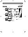
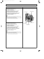
MUH-A07WV - E1
MUH-A09WV - E1
MUH-A12WV - E1
MODELS WIRING DIAGRAM
OUTDOOR UNIT
R.V.coil
21S4 heating ON
CN721
BRN
SR61
T61
BLU
TAB20
C65
52C
GRN/YLW
PE
4
3
C1
BLU
DEICER P.C.BOARD
C
WHT
RED
S
BLK
NAME
SYMBOL
NAME
SYMBOL
COMPRESSOR CAPACITOR
MF
C65
OUTDOOR FAN CAPACITOR
NR61
VARISTOR
RT61
DEFROST THERMISTOR
SURGE ABSORBER
F61
FUSE(2A)
MC
COMPRESSOR(INNER PROTECTOR)
SR61,SR62 SOLID STATE RELAY
T61
MC
R
NAME
SYMBOL
OUTDOOR FAN MOTOR(INNER FUSE) TB1,TB2 TERMINAL BLOCK
C1
DSAR
CN711
1 WHT
2 BLK
3 RED
NR61
BRN
F61
TB1
L
N
CN661
SR62
BLK
cooling OFF
MF
1
2
3
CN730
N
CIRCUIT BREAKER
230V 50Hz
RED
DSAR
FROM
INDOOR UNIT
CONNECTING
12V
POWER SUPPLY
~/N
RT61
TB2
3
TRANSFORMER
NOTE:1. About the indoor side electric wiring refer to the indoor unit electric wiring diagram for servicing.
2. Use copper conductors only. (For field wiring)
3. Symbols below indicate.
/: Terminal block,
: Connector
23
21S4
R.V. COIL
52C
COMPRESSOR CONTACTOR
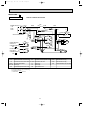
OB307C-1.qxp
04.5.11 1:16 PM
Page 24
MUX-A10WV - E1
MODEL WIRING DIAGRAM
TB1
2
1
BLU 2 BLU
1 BLU
21R1BLU
BLU
2 BLU
BLU
1
X2
8
ORN
C
C1 RED S MC
WHT
1 BLU
BLU 2
52C
BLU
21R2 BLU
F62
5 X1 1
3
6 X1 2
4
BRN
BRN
X1
8
BLK
YLW7
NAME
SYMBOL
BRN
F61
BLU
DSAR
TB2
WHT7
1
WHT 1
TB3
5 X2 1
BRN
2
WHT
WHT
BRN
CIRCUIT BREAKER
FROM INDOOR
UNIT No.B
CONNECTING
12V
COM
N
PE
FROM INDOOR
UNIT No.A
CONNECTING
12V
52C
NO
BRN
3
6 X2 2
BRN
L
BLU
POWER SUPPLY
~/N
230V
50Hz
C2
OUTDOOR UNIT
R
BLK
WHT 1 WHT
BLU 2 BLK MF
RED 3 RED
4
BLU
WHT
2
BLU 1 BLU
2
TB3
SYMBOL
NAME
SYMBOL
MF
OUTDOOR FAN MOTOR(INNER FUSE)
21R
NAME
C1
COMPRESSOR CAPACITOR
21R1
SOLENOID COIL(A)
C2
OUTDOOR FAN CAPACITOR TB1,TB2,TB3 TERMINAL BLOCK
21R2
SOLENOID COIL(B)
SURGE ABSORBER
52C
COMPRESSOR CONTACTOR
DSAR
F61,F62 FUSE(2A)
MC
COMPRESSOR(INNER PROTECTOR)
X1
RELAY(A)
X2
RELAY(B)
21R
SOLENOID COIL
NOTE:1. About the indoor side electric wiring refer to the indoor unit electric wiring diagram for servicing.
2. Use copper conductors only. (For field wiring)
3. Symbols below indicate.
/: Terminal block,
: Connector
24
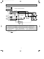
OB307C-1.qxp
04.5.11 1:16 PM
Page 25
MUX-A19WV - E1
MUX-A25WV - E1
MODELS WIRING DIAGRAM
OUTDOOR UNIT
POWER SUPPLY TB1
L
~/N
230V
N
50Hz
2
1
BLU
ORN
BRN
BLU
BRN
BRN
BLU
3
X521
T61
WHT
C2 RED
S
BLK R MC2 C
WHT
2 3 4 5 6
WHT
BLK
CN91 1
4
4
X522
NR61
3
2
1
3
BLK R MC1 C
RED LD2
RED LD1
YLW
X521
X522
RED
1
3
2
1
F61
BLU
3 2 1 CN90 OUTDOOR CONTROL
P.C. BOARD
CN71
2 TB2
S
SR861
FROM INDOOR
UNIT B
CONNECTING
12V
BRN
CN73
FROM INDOOR
UNIT A
CONNECTING
12V
C1 RED
BLU
DSAR
CIRCUIT BREAKER
BLU 1
GRN/YLW
PE
TB4
BRN 2
C61
MF61
SYMBOL
NAME
SYMBOL
NAME
SYMBOL
C1
COMPRESSOR CAPACITOR(MC1)
MC1
COMPRESSOR(INNER PROTECTOR)
TB1
C2
COMPRESSOR CAPACITOR(MC2)
MC2
COMPRESSOR(INNER PROTECTOR) TB2~TB4 TERMINAL BLOCK
OUTDOOR FAN CAPACITOR
MF61
OUTDOOR FAN MOTOR (INNER PROTECTOR)
SURGE ABSORBER
NR61
SURGE ABSORBER
X521
COMPRESSOR CONTACTOR(MC1)
SR861
OUTDOOR FAN RELAY
X522
COMPRESSOR CONTACTOR(MC2)
C61
DSAR
F61
FUSE(3.15A)
NOTE:1. About the indoor side electric wiring refer to the indoor unit electric wiring diagram for servicing.
2. Use copper conductors only. (For field wiring)
3. Symbols below indicate.
/: Terminal block,
: Connector
25
T61
NAME
TERMINAL BLOCK
TRANSFORMER
FROM INDOOR
UNIT C
CONNECTING
12V
FROM INDOOR
UNIT A
CONNECTING
12V
FROM INDOOR
UNIT B
CONNECTING
12V
26
3
2
WHT
1 CN91
COMPRESSOR CONTACTOR(MC1)
COMPRESSOR CONTACTOR(MC2)
SOLENOID COIL
SOLENOID COIL (B)
X521
X522
21RB
21R3
21R4
OUTDOOR FAN RELAY
RELAY (21RB)
RELAY (C) (21R4)
RELAY (B) (21R3)
TERMINAL BLOCK
SR861
SR863
SR865
OUTDOOR FAN CAPACITOR
SURGE ABSORBER
FUSE(3.15A)
COMPRESSOR(INNER PROTECTOR)
COMPRESSOR(INNER PROTECTOR)
C61
DSAR
F61
MC1
MC2
SOLENOID COIL (C)
NOTE:1. About the indoor side electric wiring refer to the indoor unit electric wiring diagram for servicing.
2. Use copper conductors only. (For field wiring)
3. Symbols below indicate.
/: Terminal block,
: Connector
TB1
SR866
OUTDOOR FAN MOTOR(INNER PROTECTOR) TB2~TB4 TERMINAL BLOCK
TRANSFORMER
MF61
T61
NAME
SURGE ABSORBER
21R4
NR61
SYMBOL
21R3
COMPRESSOR CAPACITOR(MC2)
21RB
S
WHT
C2 RED
WHT
BLK R MC2 C
COMPRESSOR CAPACITOR(MC1)
NAME
C61
CN86
1 2 3
CN85
1 2 3
X521
1 2 3
CN81
X522
4
C2
SYMBOL
MF61
1 2 3 4 5 6
T61
4
3
C1
BLU
NR61
3
X522
X521
S
C1 RED
BLK R MC1 C
NAME
TB3
3
2
1
BLU
3 2 1 CN90 OUTDOOR CONTROL P.C. BOARD
BLU
BLU
SYMBOL
1
2
1
1
3
2
ORN
1
BLU
2
BLU
YLW
TB2
GRN/YLW
1
2
CIRCUIT BREAKER
PE
BLU
BRN
DSAR
N
CN71
TB4
2
BRN
F61
BRN
RED LD2
TB1
RED LD1
L
BLU
CN73
CN74
BRN
SR863
BLU
BLU
SR861
WHT
BLK
BRN
SR866
POWER SUPPLY
~/N
230V
50Hz
RED
SR865
BLU
OUTDOOR UNIT
BLU
04.5.11 1:16 PM
BLU
OB307C-1.qxp
Page 26
MUX-A20WV - E1
MODEL WIRING DIAGRAM
27
2
SR865
SR866
SR867
SR868
FUSE(3.15A)
COMPRESSOR(INNER PROTECTOR)
COMPRESSOR(INNER PROTECTOR)
OUTDOOR FAN MOTOR(INNER PROTECTOR) TB1~TB4 TERMINAL BLOCK
TRANSFORMER
SURGE ABSORBER
T61
F61
MC1
MC2
MF61
21R3
RELAY (A) (21R1)
21R4
21R1
21R2
RELAY (B) (21R2)
RELAY (D) (21R4)
RELAY (C) (21R3)
21RA
21RB
RELAY (21RA)
4
X521
3
X521
NAME
21RB
SOLENOID COIL (D)
SOLENOID COIL (C)
SOLENOID COIL (B)
SOLENOID COIL (A)
SOLENOID COIL (BALANCE)
COMPRESSOR CONTACTOR(MC2)
SOLENOID COIL (BALANCE)
COMPRESSOR CONTACTOR(MC1)
21RA
CN81
2 3
1
CN82
2 3
1
NOTE:1. About the indoor side electric wiring refer to the indoor unit electric wiring diagram for servicing.
2. Use copper conductors only. (For field wiring)
3. Symbols below indicate.
/: Terminal block,
: Connector
NR61
SR864
SYMBOL
21R4
X521
SURGE ABSORBER
CN86
2 3
X522
21R3
1
RELAY (21RB)
OUTDOOR FAN CAPACITOR
CN85
2 3
4
X522
3
X522
OUTDOOR FAN RELAY
NAME
21R2
C61
21R1
DSAR
C61
1
CN84
2 3
1
CN83
2 3
1
SR863
MF61
CN91 1 2 3 4 5 6
SR861
1
COMPRESSOR CAPACITOR(MC2)
YLW
1
3
COMPRESSOR CAPACITOR(MC1)
BLU
2
1
T61
C2
BRN
1
2
3
NR61
OUTDOOR CONTROL P.C. BOARD
C1
BLU
2 TB3
2
1
3 2 1 CN90
BLU
BLU
BRN
SYMBOL
ORN
1
3
1
2
3
BLU
NAME
BLU
BLU
2
GRN/YLW
WHT
DSAR
1
2
BLU 1
RED LD1
SYMBOL
FROM INDOOR
UNIT A
CONNECTING
12V
FROM INDOOR
UNIT B
CONNECTING
12V
FROM INDOOR
UNIT C
CONNECTING
12V
FROM INDOOR
UNIT D
CONNECTING
12V
TB2
CIRCUIT BREAKER
PE
BRN
CN74
CN73
CN72
CN71
BRN
F61
SR861
WHT
BLK
N
RED
POWER SUPPLY
~/N
230V
50Hz
RED LD2
BRN
BLU
TB4
BLU
BRN 2
BLU
SR868
BLU
SR867
BLU
SR866
BLU
L TB1
BLU
SR865
BLU
SR864
BLU
SR863
BLU
S
WHT
MC2 C
RED
WHT
BLK R
C2
S
MC1 C
RED
BLK R
C1
OUTDOOR UNIT
BLU
04.5.11 1:16 PM
BLU
OB307C-1.qxp
Page 27
MUX-A26WV - E1
MODEL WIRING DIAGRAM
OB307C-1.qxp
8
04.5.11 1:16 PM
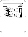
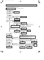
Page 28
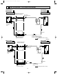
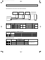
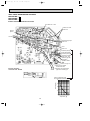
REFRIGERANT SYSTEM DIAGRAM
Unit:mm
MU-A07WV - E1
MU-A09WV - E1
MSC-A07WV - E1
MSC-A09WV - E1
INDOOR UNIT
Indoor
heat
exchanger
Refrigerant pipe [9.52
(with heat insulator)
OUTDOOR UNIT
Stop valve
(with service port)
Muffler
Indoor coil
thermistor
RT12
Outdoor
heat
exchanger
Flared connection
Room temperature
thermistor
RT11
Compressor
Flared connection
Strainer
Capillary tube
[3.0x[1.4x500(MU-A07WV)
[3.0x[1.4x700(MU-A09WV)
Refrigerant flow in cooling
Refrigerant pipe [6.35
(with heat insulator)
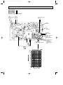
Unit:mm
MSC-A12WV - E1
INDOOR UNIT
Indoor
heat
exchanger
MU-A12WV - E1
OUTDOOR UNIT
Refrigerant pipe [12.7
(with heat insulator)
Muffler
Stop valve
(with service port)
Indoor coil
thermistor
RT12
Outdoor
heat
exchanger
Flared connection
Room temperature
thermistor
RT11
Compressor
Flared connection
Strainer
Stop valve
Capillary tube
[3.0x[1.4x550
Refrigerant pipe [6.35
(with heat insulator)
Refrigerant flow in cooling
28
OB307C-1.qxp
04.5.11 1:16 PM
Page 29
Unit:mm
MSC-A07WV - E1
MSC-A09WV - E1
INDOOR UNIT
Indoor
heat
exchanger
Indoor coil
thermistor
RT12
MUH-A07WV - E1
MUH-A09WV - E1
Refrigerant pipe [ 9.52
(with heat insulator)
Flared connection
OUTDOOR UNIT
4-way valve
Defrost
thermistor
RT61
Stop valve
(with service
port)
Muffler
Outdoor
heat
exchanger
Room temperature
thermistor
RT11
Compressor
Capillary tube
[3.0x[1.6x350(MUH-A07WV)
[3.0x[1.6x600(MUH-A09WV)
Check valve
Flared connection
Strainer
Capillary tube
[3.0x[1.4x800(2 pcs)
(MUH-A07WV)
[3.0x[1.4x500(2 pcs)
(MUH-A09WV)
R.V. coil
heating ON
cooling OFF
Capillary tube
[3.0x[1.4x1050(MUH-A07WV)
[3.0x[1.4x1300(MUH-A09WV)
Refrigerant flow in cooling
Stop valve
Refrigerant pipe [6.35
(with heat insulator)
Refrigerant flow in heating
Unit:mm
MSC-A12WV - E1
INDOOR UNIT
Indoor
heat
exchanger
Indoor coil
thermistor
RT12
MUH-A12WV - E1
Refrigerant pipe [12.7
(with heat insulator)
OUTDOOR UNIT
4-way valve
Stop valve
(with service port)
Flared connection
Muffler
Defrost
thermistor
RT61
Room temperature
thermistor
RT11
Outdoor
heat
exchanger
Capillary tube
[3.0x[1.4x500(2pcs)
Compressor
Capillary tube
[3.0x[1.6x400
Flared connection
Strainer
Capillary tube
[3.0x[1.6x1350
R.V. coil
heating ON
cooling OFF
Stop valve
Refrigerant flow in cooling
Refrigerant pipe [6.35
(with heat insulator)
Check
valve
29
Refrigerant flow in heating
OB307C-1.qxp
04.5.11 1:16 PM
Page 30
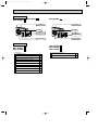
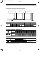
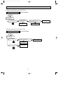
MAX. REFRIGERANT PIPING LENGTH
Refrigerant piping
Piping size O.D : mm
Max. length : m
Model
{ MSC-A07WV
MU-A07WV { MSC-A09WV
MU-A09WV { MSC-A12WV
MU-A12WV -
A
Gas
20
9.52
Liquid
Indoor unit
Outdoor unit
Gas 0.43
Gas 0
Liquid 0.5
Liquid 0
E1
E1
E1
6.35
E1
E1
12.7
25
E1
Refrigerant piping
Piping size O.D : mm
Max. length : m
Model
{ MSC-A07WV
MUH-A07WV { MSC-A09WV
MUH-A09WV { MSC-A12WV
MUH-A12WV -
Length of connecting pipe : m
A
Gas
20
9.52
Length of connecting pipe : m
Liquid
Indoor unit
Outdoor unit
Gas 0.43
Gas 0
Liquid 0.5
Liquid 0
E1
E1
E1
6.35
E1
E1
12.7
25
E1
MAX. HEIGHT DIFFERENCE
Indoor
unit
Height difference should be within
10m regardless of which unit,
indoor or outdoor position is high.
Refrigerant Piping
Max.length
A
w Max. Height
difference 10m
Outdoor unit
ADDITIONAL REFRIGERANT CHARGE(R410A : g)
Refrigerant piping length (one way)
Model
{ MSC-A07WV
MU-A07WV { MSC-A09WV
MU-A09WV { MSC-A12WV
MU-A12WV -
Outdoor unit precharged
E1
E1
E1
E1
E1
E1
7m
10m
15m
20m
0
60
160
260
25m
750
800
360
830
Calculation : Xg=20g/m x(A-7)m
Refrigerant piping length (one way)
Model
{ MSC-A07WV
MUH-A07WV { MSC-A09WV
MUH-A09WV { MSC-A12WV
MUH-A12WV -
Outdoor unit precharged
E1
E1
E1
E1
E1
E1
7m
10m
15m
20m
0
60
160
260
25m
750
1100
360
1150
Calculation : Xg=20g/m 5 x(A-7)m
30
OB307C-2.qxp
04.5.11 1:17 PM
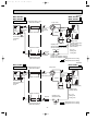
Page 31
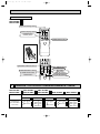
MUX-A10WV- E1
INDOOR UNIT
OUTDOOR UNIT
Room
temperature
thermistor
RT11
Refrigerant pipe
9.52
(With insulation)
Strainer
UNIT A
Unit : mm
Indoor
heat
exchanger
Stop valve
with service port
Solenoid
valve
21R
Capillary tube
[3.0 x [1.4 x 1000
Muffler
Flared connection
Refrigerant pipe
6.35
(With insulation)
Indoor coil
thermistor
RT12
Room
temperature
thermistor
RT11
UNIT B
Indoor
heat
exchanger
Solenoid valve
21R1
Stop
valve
Compressor
Strainer
Capillary tube
[3.0 x [1.4 x 400
Outdoor
heat
exchanger
Capillary tube
[3.0 x [1.6 x 900
Refrigerant pipe
9.52
(With insulation)
Stop valve
with service port
Flared connection
Solenoid valve
21R2
Indoor coil
thermistor
RT12
Refrigerant pipe
6.35
(With insulation)
Stop
valve
Capillary tube
[3.0 x [1.4 x 400
Refrigerant flow in cooling
MAX. REFRIGERANT PIPING LENGTH & MAX. HEIGHT DIFFERENCE
Indoor unit A
Indoor unit B
Max. length
difference
10m
Outdoor unit
MUX-A10WV- E1
Additional piping max. length 15m
ADDITIONAL REFRIGERANT CHARGE (R410A:g)
UNIT No.
A unit + B unit
Outdoor unit
precharged
1000g
Refrigerant piping length (one way)
10 11 12 13 14 15 16 17 18 19 20 21 22 23 24 25 26 27 28 29 30
m m m m m m m m m m m m m m m m m m m m m
0 10 20 30 40 50 60 70 80 90 100 110 120 130 140 150 160 170 180 190 200
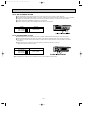
PIPING PREPARATION
1 Table below shows the specifications of pipes commercially available.
UNIT No.
A
and
B
UNIT
Pipe
For liquid
For gas
Outside diameter
mm
6.35
9.52
Insulation
thickness
8 mm
8 mm
2 Ensure that the 2 refrigerant pipes are well insulated to prevent condensation.
3 Refrigerant bending radius must be 10cm or more.
31
Insulation material
Heat resisting foam plastic
0.045 specific gravity
OB307C-2.qxp
04.5.11 1:17 PM
Page 32
Unit : mm
MUX-A19WV- E1
INDOOR UNIT
OUTDOOR UNIT
Room
temperature
thermistor
RT11
UNIT A
Refrigerant pipe
12.7
(With insulation)
Indoor
heat
exchanger
Stop valve
with service port
Muffler
Flared connection
Indoor coil
thermistor
RT12
Room
temperature
thermistor
RT11
Compressor(A)
Stop valve
Refrigerant pipe
6.35
(With insulation)
Capillary tube
Strainer
Outdoor
heat
exchanger
[3.0 x [1.4 x 850
Refrigerant pipe
9.52
(With insulation)
Muffler
UNIT B
Indoor
heat
exchanger
Flared connection
Stop valve
with
service port
Compressor(B)
Indoor coil
thermistor
RT12
Refrigerant pipe
Stop valve
Capillary tube
Strainer
[3.0 x [1.4 x 1100
6.35
(With insulation)
Refrigerant flow in cooling
32
OB307C-2.qxp
04.5.11 1:17 PM
Page 33
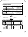
MAX.REFRIGERANT PIPING LENGTH & MAX. HEIGHT DIFFERENCE
Indoor unit B
Indoor unit A
LA
H
H
LB
Outdoor unit
MUX-A19WV - E1
UNIT No.
Max.
limits
Pipe length
Height difference (H)
No. of bends
A
LA
15m
10m
10
B
LB
15m
10m
10
ADDITIONAL REFRIGERANT CHARGE (R410A:g)
A unit
B unit
Refrigerant piping length (one way)
Outdoor unit
precharged
7m
8m
9m
10m
11m
12m
13m
14m
15m
1000g
0
20
40
60
80
100
120
140
160
Refrigerant piping length (one way,2 unit total)
Outdoor unit
precharged
7m
8m
9m
10m
11m
12m
13m
14m
15m
800g
0
20
40
60
80
100
120
140
160
PIPING PREPARATION
1Table below shows the specifications of pipes commercially available.
Outside diameter
UNIT No.
A unit
B unit
mm
Insulation
thickness
For liquid
6.35
8mm
For gas
12.7
8mm
For liquid
6.35
8mm
For gas
9.52
8mm
Pipe
2Ensure that the 2 refrigerant pipes are well insulated to prevent condensation.
3Refrigerant bending radius must be 10cm or more.
33
Insulation material
Heat resisting foam plastic
0.045 specific gravity
OB307C-2.qxp
04.5.11 1:17 PM
Page 34
Unit : mm
MUX-A20WV- E1
INDOOR UNIT
OUTDOOR UNIT
Room
temperature
thermistor
RT11
UNIT A
Refrigerant pipe
9.52
(With insulation)
Indoor
heat
exchanger
Muffler
Stop valve
with service port
Flared connection
Indoor coil
thermistor
RT12
Room
temperature
thermistor
RT11
Compressor(A)
Stop valve
Capillary tube
Refrigerant pipe
6.35
(With insulation)
Refrigerant pipe
9.52
(With insulation)
Strainer
Stop valve
with
service port
Strainer
UNIT B
Indoor
heat
exchanger
UNIT C
Muffler
Capillary tube
Flared connection
Solenoid valve
21R3
Compressor(B,C)
Refrigerant pipe
6.35
(With insulation)
Capillary tube
[3.0 x [1.6 x 900
Capillary tube Strainer
[3.0 x [1.6 x 900
Refrigerant pipe
9.52
Indoor
heat
exchanger
Stop valve
with
service port
Flared connection
Stop
valve
Indoor coil
thermistor
RT12
Solenoid
valve
21RB
[3.0 x [1.4 x 1000
Stop
valve
Indoor coil
thermistor
RT12
Room
temperature
thermistor
RT11
Outdoor
heat
exchanger
[3.0 x [1.4 x 950
Refrigerant pipe
6.35
(With insulation)
Solenoid valve
21R4
Capillary tube
[3.0 x [1.6 x 900
34
Refrigerant flow in cooling
OB307C-2.qxp
04.5.11 1:17 PM
Page 35
MAX.REFRIGERANT PIPING LENGTH & MAX. HEIGHT DIFFERENCE
Indoor unit A
Indoor unit C
Indoor unit B
H
LA
LB
H
LC
H
Outdoor unit
MUX-A20WV - E1
UNIT No.
Max.
limits
Pipe length
A
LA
B
LB
C
LC
Height difference (H)
No. of bends
10m
10
15m
15m
LB
15m
+
LC
Total
30m
10m
10
10m
10
Total
15
ADDITIONAL REFRIGERANT CHARGE (R410A:g)
A unit
B unit + C unit
Refrigerant piping length (one way)
Outdoor unit
precharged
7m
8m
9m
10m
11m
12m
13m
14m
15m
800g
0
20
40
50
80
100
120
140
160
Refrigerant piping length (one way, 2 unit total)
Outdoor unit
precharged 10 11 12 13 14 15 16 17 18 19 20 21 22 23 24 25 26 27 28 29 30
m m m m m m m m m m m m m m m m m m m m m
1000g
0 10 20 30 40 50 60 70 80 90 100 110 120 130 140 150 160 170 180 190 200
PIPING PREPARATION
1Table below shows the specifications of pipes commercially available.
Outside diameter
UNIT No.
mm
Insulation
thickness
Pipe
A , B and
For liquid
6.35
8mm
C unit
For gas
9.52
8mm
2Ensure that the 2 refrigerant pipes are well insulated to prevent condensation.
3Refrigerant bending radius must be 100mm or more.
35
Insulation material
Heat resisting foam plastic
0.045 specific gravity
OB307C-2.qxp
04.5.11 1:17 PM
Page 36
Unit : mm
MUX-A25WV- E1
INDOOR UNIT
OUTDOOR UNIT
Room
temperature
thermistor
RT11
UNIT A
Refrigerant pipe
12.7
(With insulation)
Indoor
heat
exchanger
Stop valve
with service port
Muffler
Flared connection
Indoor coil
thermistor
RT12
Room
temperature
thermistor
RT11
Compressor(A)
Stop valve
Refrigerant pipe
6.35
(With insulation)
Capillary tube
Strainer
Outdoor
heat
exchanger
[3.0 x [1.4 x 700
Refrigerant pipe
12.7
(With insulation)
Muffler
UNIT B
Indoor
heat
exchanger
Flared connection
Stop valve
with
service port
Compressor(B)
Indoor coil
thermistor
RT12
Refrigerant pipe
6.35
(With insulation)
Stop valve
Capillary tube
Strainer
[3.0 x [1.4 x 700
Refrigerant flow in cooling
36
OB307C-2.qxp
04.5.11 1:17 PM
Page 37
MAX.REFRIGERANT PIPING LENGTH & MAX. HEIGHT DIFFERENCE
Indoor unit A
Indoor unit B
H
LA
LB
H
Outdoor unit
MUX-A25WV - E1
UNIT No.
Max.
limits
Pipe length
Height difference (H)
No. of bends
A
LA
15m
10m
10
B
LB
15m
10m
10
ADDITIONAL REFRIGERANT CHARGE (R410A:g)
A unit
B unit
Refrigerant piping length (one way)
Outdoor unit
precharged
7m
8m
9m
10m
11m
12m
13m
14m
15m
950g
0
20
40
60
80
100
120
140
160
Refrigerant piping length (one way)
Outdoor unit
precharged
7m
8m
9m
10m
11m
12m
13m
14m
15m
950g
0
20
40
60
80
100
120
140
160
PIPING PREPARATION
1Table below shows the specifications of pipes commercially available.
Outside diameter
UNIT No.
A and B unit
mm
Insulation
thickness
For liquid
6.35
8mm
For gas
12.7
8mm
Pipe
2Ensure that the 2 refrigerant pipes are well insulated to prevent condensation.
3Refrigerant bending radius must be 10cm or more.
37
Insulation material
Heat resisting foam plastic
0.045 specific gravity
OB307C-2.qxp
04.5.11 1:17 PM
Page 38
MUX-A26WV- E1
INDOOR UNIT
Room
temperature
thermistor
RT11
OUTDOOR UNIT
Refrigerant pipe
{12.7
(With insulation)
Strainer
UNIT A
Unit : mm
Indoor
heat
exchanger
Stop valve
with service port
Solenoid
valve
21RA
Capillary tube
[3.0 x [1.4 x 1000
Muffler
Flared connection
Indoor coil
thermistor
RT12
Room
temperature
thermistor
RT11
UNIT B
Refrigerant pipe
{6.35
(With insulation)
Solenoid valve
21R1
Stop
valve
Strainer
Capillary tube
[3.0 x [1.8 x 700
Capillary tube
[3.0 x [2.0 x 700
Refrigerant pipe
{12.7
(With insulation)
Indoor
heat
exchanger
Compressor 1
Stop valve
with service port
Flared connection
Solenoid valve
21R2
Indoor coil
thermistor
RT12
Room
temperature
thermistor
RT11
Refrigerant pipe
{6.35
(With insulation)
Stop
valve
Capillary tube
[3.0 x [1.8 x 700
Outdoor
heat
exchanger
Refrigerant pipe
{9.52
(With insulation)
Strainer
UNIT C
Indoor
heat
exchanger
Stop valve
with service port
Solenoid
valve
21RB
Capillary tube
[3.0 x [1.4 x 1000
Muffler
Flared connection
Indoor coil
thermistor
RT12
Room
temperature
thermistor
RT11
UNIT D
Refrigerant pipe
{6.35
(With insulation)
Solenoid valve
21R3
Stop
valve
Capillary tube
[3.0 x [1.6 x 600
Strainer
Capillary tube
[3.0 x [1.8 x 800
Refrigerant pipe
{9.52
(With insulation)
Indoor
heat
exchanger
Compressor 2
Stop valve
with service port
Flared connection
Solenoid valve
21R4
Indoor coil
thermistor
RT12
Refrigerant pipe
{6.35
(With insulation)
Stop
valve
Capillary tube
[3.0 x [1.6 x 600
Refrigerant flow in cooling
38
OB307C-2.qxp
04.5.11 1:17 PM
Page 39
MAX.REFRIGERANT PIPING LENGTH & MAX. HEIGHT DIFFERENCE
Indoor unit A
LA
Indoor unit B
H
Indoor unit C
LB
H
LC
Indoor unit D
H
LD
H
Outdoor unit
MUX-A26WV- E1
UNIT No.
Max.
limits
Pipe length
A
LA
B
LB
Height difference (H)
LA
15m
+
C
LC
D
LD
15m
LB
15m
LC
+
15m
LD
No. of bends
Total
30m
10m
10
10m
10
Total
30m
10m
10
10m
10
Total
15
Total
15
ADDITIONAL REFRIGERANT CHARGE (R410A:g)
UNIT No.
Outdoor unit
precharged
Refrigerant piping length (one way, 2 unit total)
10 11 12 13 14 15 16 17 18 19 20 21 22 23 24 25 26 27 28 29 30
m m m m m m m m m m m m m m m m m m m m m
A unit + B unit
1050g
0
10 20 30 40 50 60 70 80 90 100 110 120 130 140 150 160 170 180 190 200
C unit + D unit
1050g
0
10 20 30 40 50 60 70 80 90 100 110 120 130 140 150 160 170 180 190 200
PIPING PREPARATION
Outside diameter
UNIT No.
A and B unit
C and D unit
mm
Insulation
thickness
For liquid
6.35
8mm
For gas
12.7
8mm
For liquid
6.35
8mm
For gas
9.52
8mm
Pipe
39
Insulation material
Heat resisting foam plastic
0.045 specific gravity
OB307C-2.qxp
9
04.5.11 1:17 PM
Page 40
PERFORMANCE CURVES
MSC-A07WV - E1
MSC-A09WV - E1
MSC-A12WV - E1
MSC-A07YV - E1
MSC-A09YV - E1
MSC-A12YV - E1
MU-A07WV - E1
MU-A09WV - E1
MU-A12WV - E1
MUH-A07WV - E1
MUH-A09WV - E1
MUH-A12WV - E1
MUX-A10WV
MUX-A19WV
MUX-A20WV
MUX-A25WV
MUX-A26WV
- E1
- E1
- E1
- E1
- E1
The standard data contained in these specifications apply only to the operation of the air conditioner under normal conditions,
since operating conditions vary according to the areas where these units are installed. The following information has been provided to clarify the operating characteristics of the air conditioner under the conditions indicated by the performance curve.
(1) GUARANTEED VOLTAGE
198~264V
(2) AIR FLOW
Air flow should be set at MAX.
(3) MAIN READINGS
}
(1) Indoor intake air wet-bulb temperature :
°CWB
Cooling
(2) Indoor outlet air wet-bulb temperature :
°CWB
(3) Outdoor intake air dry-bulb temperature :
°CDB
(4) Total input:
W
(5) Indoor intake air dry-bulb temperature :
°CDB
Heating <MUH-A07/A09/A12WV>
(6) Outdoor intake air wet-bulb temperature :
°CWB
(7) Total input :
W
Indoor air wet/dry-bulb temperature difference on the left side of the chart on page 40,41 and 44 shows the difference
between the indoor intake air wet/dry-bulb temperature and the indoor outlet air wet/dry-bulb temperature for your reference at service.
}
How to measure the indoor air wet-bulb/dry-bulb temperature difference
1.
2.
3.
4.
5.
6.
7.
Attach at least 2 sets of wet-and dry-bulb thermometers to the indoor air intake as shown in the figure, and at least 2 sets
of wet-and dry-bulb thermometers to the indoor air outlet. The thermometers must be attached to the position where air
speed is high.
Attach at least 2 sets of wet-and dry-bulb thermometers to the outdoor air intake.
Cover the thermometers to prevent direct rays of the sun.
Check that the air filter is cleaned.
Open windows and doors of room.
Press the EMERGENCY OPERATION switch once(twice) to start the EMERGENCY COOL
(HEAT<MUH-A07/A09/A12WV>) MODE.
When system stabilizes after more than 15 minutes, measure temperature and take an average temperature.
10 minutes later, measure temperature again and check that the temperature does not change.
INDOOR UNIT
OUTDOOR UNIT
Wet-and dry-bulb
thermometers
Wet-and dry-bulb
thermometers
9-1.CAPACITY AND THE INPUT CURVES
8.8 9.8
7.1
8.0 8.9
6.4
7.2 8.1
5.8
6.5 7.2
5.1
5.7 6.4
MSC-A12WV - E1
(MU-A12WV - E1 )
7.8
MSC-A09WV - E1
(MU-A09WV - E1 )
9.6 10.8
MSC-A07WV - E1
(MU-A07WV - E1 )
8.5
40
04.5.11 1:17 PM
Page 41
8.8 9.7
7.1
8.0 8.8
6.4
7.2 7.9
5.8
6.5 7.1
5.1
5.1 6.3
MSC-A12WV - E1
(MUH-A12WV - E1 )
9.6 10.6
7.8
MSC-A09WV - E1
(MUH-A09WV - E1 )
8.5
MSC-A07WV - E1
(MUH-A07WV - E1 )
18.8 23.3
16.3
17.2 21.4
14.8
15.7 19.4
13.3
14.1 17.5
11.8
12.5 15.5
10.4
11.0 13.6
8.9
9.4 11.7
MSC-A12WV - E1
(MUH-A12WV - E1 )
20.4 25.2
17.8
MSC-A07WV - E1
(MUH-A07WV - E1 )
19.2
MSC-A09WV - E1
(MUH-A09WV - E1 )
OB307C-2.qxp
NOTE:The above curves are for the heating operation without any frost.
9-2.OUTDOOR LOW PRESSURE AND OUTDOOR UNIT CURRENT
COOL operation
Dry-bulb temperature
Relative humidity(%)
20
50
25
60
30
70
Air flow should be set at MAX.
The unit of pressure has been changed to MPa on the international system of units(SI unit system).
f[Gauge] )
The conversion factor is : 1(MPa[Gauge]) =10.2(kgf/f
(kgf/F[Gauge])(MPa[Gauge])
12
MU-A07WV - E1
MU-A07WV - E1
1.2
11
1.1
10
1.0
4.0
Outdoor unit current (A)
➁
③
Both indoor and outdoor unit are under the same temperature/humidity condition.
Outdoor low pressure
①
230V
9
0.9
8
0.8
7
0.7
15
20
50
25
60
30
70(%)
35(:)
Ambient temperature(˚C)
Ambient humidity(%)
3.5
230V
3.0
2.5
2.0
15
20
50
25
60
30
70(%)
Ambient temperature(˚C)
Ambient humidity(%)
41
35(:)
04.5.11 1:17 PM
Outdoor low pressure
(kgf/F[Gauge])(MPa[Gauge])
12
1.2
11
1.1
10
1.0
9
0.9
8
0.8
7
0.7
15
Page 42
MU-A09WV - E1
230V
20
50
25
60
30
70(%)
3.5
230V
3.0
2.5
2.0
15
35(:)
1.2
11
1.1
10
1.0
9
0.9
8
0.8
7
0.7
15
MU-A12WV - E1
230V
20
50
25
60
30
70(%)
12
1.2
11
1.1
10
1.0
230V
5.0
4.0
3.0
15
35(:)
MUH-A07WV - E1
8
0.8
7
0.7
15
20
50
25
60
30
70(%)
1.2
11
1.1
10
1.0
9
0.9
8
0.8
7
0.7
15
2.5
4.0
230V
25
60
30
70(%)
20
50
25
60
30
70(%)
35(:)
Ambient temperature(˚C)
Ambient humidity(%)
MUH-A09WV - E1
20
50
35(:)
230V
3.0
2.0
15
35(:)
Outdoor unit current (A)
Outdoor low pressure
12
30
70(%)
3.5
Ambient temperature(˚C)
Ambient humidity(%)
(kgf/F[Gauge])(MPa[Gauge])
25
60
MUH-A07WV - E1
4.0
Outdoor unit current (A)
Outdoor low pressure
0.9
20
50
Ambient temperature(˚C)
Ambient humidity(%)
230V
9
30
35(:)
70(%)
6.0
Ambient temperature(˚C)
Ambient humidity(%)
(kgf/F[Gauge])(MPa[Gauge])
25
60
MU-A12WV - E1
7.0
Outdoor unit current (A)
Outdoor low pressure
12
20
50
Ambient temperature(˚C)
Ambient humidity(%)
Ambient temperature(˚C)
Ambient humidity(%)
(kgf/F[Gauge])(MPa[Gauge])
MU-A09WV - E1
4.0
Outdoor unit current (A)
OB307C-2.qxp
3.5
230V
3.0
2.5
2.0
15
35(:)
Ambient temperature(˚C)
Ambient humidity(%)
MUH-A09WV - E1
20
50
25
60
30
70(%)
Ambient temperature(˚C)
Ambient humidity(%)
42
35(:)
04.5.11 1:17 PM
Page 43
MUH-A12WV - E1
(kgf/F[Gauge])(MPa[Gauge])
Outdoor low pressure
13
12
11
10
9
8
7
1.2
230V
1.1
1.0
0.9
0.8
0.7
15
20
50
25
60
MUH-A12WV - E1
6.0
1.3
Outdoor unit current (A)
OB307C-2.qxp
30
70(%)
5.0
230V
4.0
3.0
2.0
15
35(:)
20
50
25
60
35(:)
30
70(%)
Ambient temperature(˚C)
Ambient humidity(%)
Ambient temperature(˚C)
Ambient humidity(%)
HEAT operation
Condition indoor:Dry bulb temperature 20.0°C
Wet bulb temperature 14.5°C
MUH-A07WV - E1
3.5
230V
3.0
2.5
2.0
5
7
10
15
20
25(:)
Ambient temperature(˚C)
MUH-A12WV - E1
Outdoor unit current (A)
5.5
230V
5.0
4.5
7
10
15
20
4.5
230V
4.0
3.5
3.0
5
7
10
15
20
Ambient temperature(˚C)
6.0
4.0
5
MUH-A09WV - E1
5.0
Outdoor unit current (A)
4.0
Outdoor unit current (A)
Outdoor:Dry bulb temperature 7,15,20°C
Wet bulb temperature 6,12,14.5°C
25(:)
Ambient temperature(˚C)
43
25(:)
OB307C-2.qxp
04.5.11 1:17 PM
Page 44
9.4
10.2
9.4
9.5
10.8
10.2
10.2
10.3
8.6
9.4
8.6
8.7
9.9
9.4
9.4
9.4
7.8
8.5
7.8
7.9
9.0
8.5
8.5
8.6
7.1
7.7
7.1
7.1
8.1
7.7
7.7
7.7
6.3
6.9
6.3
6.4
7.3
6.9
6.9
6.9
5.6
6.1
5.6
5.7
6.4
6.1
6.1
6.2
MUX-A10WV- E1
(Indoor unit A or B)
MUX-A19WV- E1
(Indoor unit A)
MUX-A19WV- E1
(Indoor unit B)
MUX-A20WV- E1
(Indoor unit A)
MUX-A20WV- E1
(Indoor unit B or C)
MUX-A25WV- E1
(Indoor unit A or B)
MUX-A26WV- E1
(Indoor unit A or B)
MUX-A26WV- E1
(Indoor unit C or D)
Indoor air WB temperature
difference (deg.)
9-3.CAPACITY AND THE INPUT CURVES
(ONE INDOOR UNIT WITH ONE OUTDOOR UNIT)
9-4.OUTDOOR LOW PRESSURE AND OUTDOOR UNIT CURRENT
COOL operation
① Both indoor and outdoor unit are under same temperature/humidity condition.
➁
③
Dry-bulb temperature
Relative humidity (%)
20
50
25
60
30
70
Air flow should be set at MAX.
The unit of pressure has been changed to MPa on the international system of units(SI unit system).
f[Gauge] )
The conversion factor is : 1(MPa[Gauge]) =10.2(kgf/f
MUX-A10WV- E1
12 1.2
11 1.1
10 1.0
230V
9 0.9
8 0.8
7 0.7
Outdoor unit current (A)
Outdoor low pressure (kgf/F[Gauge])
(kgf/F[Gauge])(MPa[Gauge]) Single operation (Unit A or B)
1.3
4.0
13
25
30
(˚C)
20
60
70
(%)
50
Ambient temperature(˚C)
Ambient humidity(%)
3.5
3.0
230V
2.5
2.0
25
30
(˚C)
20
60
70
(%)
50
Ambient temperature(˚C)
Ambient humidity(%) ˚C)
(%)
MUX-A19WV- E1
9 0.9
8 0.8
7 0.7
6 0.6
230V
25
30
(˚C)
20
60
70
(%)
50
Ambient temperature(˚C)
Ambient humidity(%)
6.0
5.0
230V
4.0
3.0
25
30
(˚C)
20
60
70
(%)
50
Ambient temperature(˚C)
Ambient humidity(%)
44
Single operation (Unit B)
4.0
12 1.2
11 1.1
10 1.0
9 0.9
8 0.8
7 0.7
230V
Outdoor unit current (A)
10 1.0
7.0
Outdoor low pressure (kgf/F[Gauge])
11 1.1
(kgf/F[Gauge])(MPa[Gauge])
1.3
13
Single operation (Unit A)
Outdoor unit current (A)
Outdoor low pressure (kgf/F[Gauge])
(kgf/F[Gauge])(MPa[Gauge])
1.2
12
25
30
(˚C)
20
60
70
(%)
50
Ambient temperature(˚C)
Ambient humidity(%)
3.5
3.0
230V
2.5
2.0
25
30
(˚C)
20
60
70
(%)
50
Ambient temperature(˚C)
Ambient humidity(%)
OB307C-2.qxp
04.5.11 1:17 PM
Page 45
MUX-A20WV- E1
10 1.0
230V
8 0.8
7 0.7
6 0.6
25
30
(˚C)
20
60
70
(%)
50
Ambient temperature(˚C)
Ambient humidity(%)
Outdoor low pressure (kgf/F[Gauge])
11 1.1
9 0.9
(kgf/F[Gauge])(MPa[Gauge]) Single operation (Unit B or C)
0.9
6.0
9
5.0
4.0
230V
3.0
2.0
25
30
(˚C)
20
60
70
(%)
50
Ambient temperature(˚C)
Ambient humidity(%)
8 0.8
7 0.7
230V
6 0.6
5 0.5
4 0.4
Outdoor unit current (A)
Single operation (Unit A)
Outdoor unit current (A)
Outdoor low pressure (kgf/F[Gauge])
(kgf/F[Gauge])(MPa[Gauge])
1.2
12
5.0
4.0
3.0
25
30
(˚C)
20
60
70
(%)
50
Ambient temperature(˚C)
Ambient humidity(%)
230V
25
30
(˚C)
20
60
70
(%)
50
Ambient temperature(˚C)
Ambient humidity(%)
MUX-A25WV- E1
11 1.1
10 1.0
9 0.9
230V
8 0.8
7 0.7
6 0.6
Outdoor unit current (A)
Outdoor low pressure (kgf/F[Gauge])
(kgf/F[Gauge])(MPa[Gauge]) Single operation (Unit A or B)
1.2
7.0
12
25
30
(˚C)
20
60
70
(%)
50
Ambient temperature(˚C)
Ambient humidity(%)
6.0
230V
5.0
4.0
25
30
(˚C)
20
60
70
(%)
50
Ambient temperature(˚C)
Ambient humidity(%)
MUX-A26WV- E1
230V
8 0.8
7 0.7
6 0.6
25
30
(˚C)
20
60
70
(%)
50
Ambient temperature(˚C)
Ambient humidity(%)
5.0
230V
4.0
3.0
25
30
(˚C)
20
60
70
(%)
50
Ambient temperature(˚C)
Ambient humidity(%)
45
10 1.0
9 0.9
230V
8 0.8
7 0.7
6 0.6
Outdoor unit current (A)
9 0.9
(kgf/F[Gauge])(MPa[Gauge])Single operation (Unit C or D)
5.0
1.1
11
Outdoor low pressure (kgf/F[Gauge])
10 1.0
Outdoor unit current (A)
Outdoor low pressure (kgf/F[Gauge])
(kgf/F[Gauge])(MPa[Gauge]) Single operation (Unit A or B)
6.0
1.1
11
25
30
(˚C)
20
60
70
(%)
50
Ambient temperature(˚C)
Ambient humidity(%)
4.0
230V
3.0
2.0
25
30
(˚C)
20
60
70
(%)
50
Ambient temperature(˚C)
Ambient humidity(%)
OB307C-2.qxp
04.5.11 1:17 PM
Page 46
PERFORMANCE DATA
COOL operation (230V)
MSC-A07WV - E1 : MU-A07WV - E1
CAPACITY : 2.3(kW) SHF : 0.74 INPUT : 710(W)
OUTDOOR DB(:)
21
25
27
30
INDOOR INDOOR
DB(:) WB(:) Q SHC SHF INPUT Q SHC SHF INPUT Q SHC SHF INPUT Q SHC SHF INPUT
21
18
2.70 1.51 0.56 568 2.59 1.45 0.56 596 2.48 1.39 0.56 625 2.39 1.34 0.56 653
21
20
2.82 1.24 0.44 596 2.70 1.19 0.44 632 2.62 1.15 0.44 646 2.53 1.11 0.44 675
22
18
2.70 1.62 0.60 568 2.59 1.55 0.60 596 2.48 1.49 0.60 625 2.39 1.44 0.60 653
22
20
2.82 1.35 0.48 596 2.70 1.30 0.48 632 2.62 1.26 0.48 646 2.53 1.21 0.48 675
22
22
2.93 1.06 0.36 618 2.83 1.02 0.36 657 2.76 0.99 0.36 675 2.65 0.95 0.36 703
23
18
2.70 1.73 0.64 568 2.59 1.66 0.64 596 2.48 1.59 0.64 625 2.39 1.53 0.64 653
23
20
2.82 1.47 0.52 596 2.70 1.41 0.52 632 2.62 1.36 0.52 646 2.53 1.32 0.52 675
23
22
2.93 1.17 0.40 618 2.83 1.13 0.40 657 2.76 1.10 0.40 675 2.65 1.06 0.40 703
24
18
2.70 1.84 0.68 568 2.59 1.76 0.68 596 2.48 1.69 0.68 625 2.39 1.63 0.68 653
24
20
2.82 1.58 0.56 596 2.70 1.51 0.56 632 2.62 1.47 0.56 646 2.53 1.42 0.56 675
24
22
2.93 1.29 0.44 618 2.83 1.24 0.44 657 2.76 1.21 0.44 675 2.65 1.16 0.44 703
24
24
3.08 0.99 0.32 646 2.97 0.95 0.32 682 2.90 0.93 0.32 703 2.81 0.90 0.32 738
25
18
2.70 1.95 0.72 568 2.59 1.86 0.72 596 2.48 1.79 0.72 625 2.39 1.72 0.72 653
25
20
2.82 1.69 0.60 596 2.70 1.62 0.60 632 2.62 1.57 0.60 646 2.53 1.52 0.60 675
25
22
2.93 1.41 0.48 618 2.83 1.36 0.48 657 2.76 1.32 0.48 675 2.65 1.27 0.48 703
25
24
3.08 1.11 0.36 646 2.97 1.07 0.36 682 2.90 1.04 0.36 703 2.81 1.01 0.36 738
26
18
2.70 2.05 0.76 568 2.59 1.97 0.76 596 2.48 1.89 0.76 625 2.39 1.82 0.76 653
26
20
2.82 1.80 0.64 596 2.70 1.73 0.64 632 2.62 1.68 0.64 646 2.53 1.62 0.64 675
26
22
2.93 1.52 0.52 618 2.83 1.47 0.52 657 2.76 1.44 0.52 675 2.65 1.38 0.52 703
26
24
3.08 1.23 0.40 646 2.97 1.19 0.40 682 2.90 1.16 0.40 703 2.81 1.12 0.40 738
26
26
3.17 0.89 0.28 682 3.08 0.86 0.28 717 3.04 0.85 0.28 738 2.94 0.82 0.28 760
27
18
2.70 2.16 0.80 568 2.59 2.07 0.80 596 2.48 1.99 0.80 625 2.39 1.91 0.80 653
27
20
2.82 1.92 0.68 596 2.70 1.84 0.68 632 2.62 1.78 0.68 646 2.53 1.72 0.68 675
27
22
2.93 1.64 0.56 618 2.83 1.58 0.56 657 2.76 1.55 0.56 675 2.65 1.48 0.56 703
27
24
3.08 1.36 0.44 646 2.97 1.31 0.44 682 2.90 1.28 0.44 703 2.81 1.23 0.44 738
27
26
3.17 1.02 0.32 682 3.08 0.99 0.32 717 3.04 0.97 0.32 738 2.94 0.94 0.32 760
28
18
2.70 2.27 0.84 568 2.59 2.17 0.84 596 2.48 2.09 0.84 625 2.39 2.01 0.84 653
28
20
2.82 2.03 0.72 596 2.70 1.95 0.72 632 2.62 1.89 0.72 646 2.53 1.82 0.72 675
28
22
2.93 1.76 0.60 618 2.83 1.70 0.60 657 2.76 1.66 0.60 675 2.65 1.59 0.60 703
28
24
3.08 1.48 0.48 646 2.97 1.42 0.48 682 2.90 1.39 0.48 703 2.81 1.35 0.48 738
28
26
3.17 1.14 0.36 682 3.08 1.11 0.36 717 3.04 1.09 0.36 738 2.94 1.06 0.36 760
29
18
2.70 2.38 0.88 568 2.59 2.28 0.88 596 2.48 2.19 0.88 625 2.39 2.10 0.88 653
29
20
2.82 2.14 0.76 596 2.70 2.05 0.76 632 2.62 1.99 0.76 646 2.53 1.92 0.76 675
29
22
2.93 1.88 0.64 618 2.83 1.81 0.64 657 2.76 1.77 0.64 675 2.65 1.69 0.64 703
29
24
3.08 1.60 0.52 646 2.97 1.54 0.52 682 2.90 1.51 0.52 703 2.81 1.46 0.52 738
29
26
3.17 1.27 0.40 682 3.08 1.23 0.40 717 3.04 1.21 0.40 738 2.94 1.18 0.40 760
30
18
2.70 2.49 0.92 568 2.59 2.38 0.92 596 2.48 2.29 0.92 625 2.39 2.20 0.92 653
30
20
2.82 2.25 0.80 596 2.70 2.16 0.80 632 2.62 2.10 0.80 646 2.53 2.02 0.80 675
30
22
2.93 1.99 0.68 618 2.83 1.92 0.68 657 2.76 1.88 0.68 675 2.65 1.80 0.68 703
30
24
3.08 1.73 0.56 646 2.97 1.66 0.56 682 2.90 1.62 0.56 703 2.81 1.57 0.56 738
30
26
3.17 1.40 0.44 682 3.08 1.36 0.44 717 3.04 1.34 0.44 738 2.94 1.30 0.44 760
31
18
2.70 2.59 0.96 568 2.59 2.48 0.96 596 2.48 2.38 0.96 625 2.39 2.30 0.96 653
31
20
2.82 2.37 0.84 596 2.70 2.27 0.84 632 2.62 2.20 0.84 646 2.53 2.13 0.84 675
31
22
2.93 2.11 0.72 618 2.83 2.04 0.72 657 2.76 1.99 0.72 675 2.65 1.90 0.72 703
31
24
3.08 1.85 0.60 646 2.97 1.78 0.60 682 2.90 1.74 0.60 703 2.81 1.68 0.60 738
31
26
3.17 1.52 0.48 682 3.08 1.48 0.48 717 3.04 1.46 0.48 738 2.94 1.41 0.48 760
32
18
2.70 2.70 1.00 568 2.59 2.59 1.00 596 2.48 2.48 1.00 625 2.39 2.39 1.00 653
32
20
2.82 2.48 0.88 596 2.70 2.38 0.88 632 2.62 2.31 0.88 646 2.53 2.23 0.88 675
32
22
2.93 2.23 0.76 618 2.83 2.15 0.76 657 2.76 2.10 0.76 675 2.65 2.01 0.76 703
32
24
3.08 1.97 0.64 646 2.97 1.90 0.64 682 2.90 1.85 0.64 703 2.81 1.80 0.64 738
32
26
3.17 1.65 0.52 682 3.08 1.60 0.52 717 3.04 1.58 0.52 738 2.94 1.53 0.52 760
NOTE
Q :Total capacity (kW)
SHC :Sensible heat capacity (kW)
SHF :Sensible heat factor
INPUT :Total power input (W)
46
DB :Dry-bulb temperature
WB :Wet-bulb temperature
OB307C-2.qxp
04.5.11 1:17 PM
Page 47
PERFORMANCE DATA
COOL operation (230V)
MSC-A07WV - E1 : MU-A07WV - E1
CAPACITY : 2.3(kW) SHF : 0.74 INPUT : 710(W)
INDOOR INDOOR
DB(:) WB(:)
21
21
22
22
22
23
23
23
24
24
24
24
25
25
25
25
26
26
26
26
26
27
27
27
27
27
28
28
28
28
28
29
29
29
29
29
30
30
30
30
30
31
31
31
31
31
32
32
32
32
32
NOTE
18
20
18
20
22
18
20
22
18
20
22
24
18
20
22
24
18
20
22
24
26
18
20
22
24
26
18
20
22
24
26
18
20
22
24
26
18
20
22
24
26
18
20
22
24
26
18
20
22
24
26
Q
2.25
2.37
2.25
2.37
2.51
2.25
2.37
2.51
2.25
2.37
2.51
2.65
2.25
2.37
2.51
2.65
2.25
2.37
2.51
2.65
2.78
2.25
2.37
2.51
2.65
2.78
2.25
2.37
2.51
2.65
2.78
2.25
2.37
2.51
2.65
2.78
2.25
2.37
2.51
2.65
2.78
2.25
2.37
2.51
2.65
2.78
2.25
2.37
2.51
2.65
2.78
OUTDOOR DB(:)
35
40
SHC SHF INPUT Q SHC SHF INPUT
1.26 0.56 696 2.07 1.16 0.56 738
1.04 0.44 724 2.21 0.97 0.44 760
1.35 0.60 696 2.07 1.24 0.60 738
1.14 0.48 724 2.21 1.06 0.48 760
0.90 0.36 753 2.35 0.84 0.36 795
1.44 0.64 696 2.07 1.32 0.64 738
1.23 0.52 724 2.21 1.15 0.52 760
1.00 0.40 753 2.35 0.94 0.40 795
1.53 0.68 696 2.07 1.41 0.68 738
1.33 0.56 724 2.21 1.24 0.56 760
1.10 0.44 753 2.35 1.03 0.44 795
0.85 0.32 781 2.48 0.79 0.32 817
1.62 0.72 696 2.07 1.49 0.72 738
1.42 0.60 724 2.21 1.32 0.60 760
1.20 0.48 753 2.35 1.13 0.48 795
0.95 0.36 781 2.48 0.89 0.36 817
1.71 0.76 696 2.07 1.57 0.76 738
1.52 0.64 724 2.21 1.41 0.64 760
1.30 0.52 753 2.35 1.22 0.52 795
1.06 0.40 781 2.48 0.99 0.40 817
0.78 0.28 809 2.62 0.73 0.28 845
1.80 0.80 696 2.07 1.66 0.80 738
1.61 0.68 724 2.21 1.50 0.68 760
1.40 0.56 753 2.35 1.31 0.56 795
1.16 0.44 781 2.48 1.09 0.44 817
0.89 0.32 809 2.62 0.84 0.32 845
1.89 0.84 696 2.07 1.74 0.84 738
1.71 0.72 724 2.21 1.59 0.72 760
1.50 0.60 753 2.35 1.41 0.60 795
1.27 0.48 781 2.48 1.19 0.48 817
1.00 0.36 809 2.62 0.94 0.36 845
1.98 0.88 696 2.07 1.82 0.88 738
1.80 0.76 724 2.21 1.68 0.76 760
1.60 0.64 753 2.35 1.50 0.64 795
1.38 0.52 781 2.48 1.29 0.52 817
1.11 0.40 809 2.62 1.05 0.40 845
2.07 0.92 696 2.07 1.90 0.92 738
1.90 0.80 724 2.21 1.77 0.80 760
1.70 0.68 753 2.35 1.60 0.68 795
1.48 0.56 781 2.48 1.39 0.56 817
1.22 0.44 809 2.62 1.15 0.44 845
2.16 0.96 696 2.07 1.99 0.96 738
1.99 0.84 724 2.21 1.85 0.84 760
1.81 0.72 753 2.35 1.69 0.72 795
1.59 0.60 781 2.48 1.49 0.60 817
1.34 0.48 809 2.62 1.26 0.48 845
2.25 1.00 696 2.07 2.07 1.00 738
2.08 0.88 724 2.21 1.94 0.88 760
1.91 0.76 753 2.35 1.78 0.76 795
1.69 0.64 781 2.48 1.59 0.64 817
1.45 0.52 809 2.62 1.36 0.52 845
Q :Total capacity (kW)
SHC :Sensible heat capacity (kW)
Q
1.99
2.13
1.99
2.13
2.27
1.99
2.13
2.27
1.99
2.13
2.27
2.42
1.99
2.13
2.27
2.42
1.99
2.13
2.27
2.42
2.54
1.99
2.13
2.27
2.42
2.54
1.99
2.13
2.27
2.42
2.54
1.99
2.13
2.27
2.42
2.54
1.99
2.13
2.27
2.42
2.54
1.99
2.13
2.27
2.42
2.54
1.99
2.13
2.27
2.42
2.54
SHF :Sensible heat factor
INPUT :Total power input (W)
47
SHC
1.11
0.94
1.19
1.02
0.82
1.27
1.11
0.91
1.35
1.19
1.00
0.77
1.43
1.28
1.09
0.87
1.51
1.36
1.18
0.97
0.71
1.59
1.45
1.27
1.06
0.81
1.67
1.53
1.36
1.16
0.91
1.75
1.62
1.45
1.26
1.02
1.83
1.70
1.54
1.35
1.12
1.91
1.79
1.63
1.45
1.22
1.99
1.87
1.72
1.55
1.32
43
SHF INPUT
0.56 753
0.44 781
0.60 753
0.48 781
0.36 809
0.64 753
0.52 781
0.40 809
0.68 753
0.56 781
0.44 809
0.32 834
0.72 753
0.60 781
0.48 809
0.36 834
0.76 753
0.64 781
0.52 809
0.40 834
0.28 863
0.80 753
0.68 781
0.56 809
0.44 834
0.32 863
0.84 753
0.72 781
0.60 809
0.48 834
0.36 863
0.88 753
0.76 781
0.64 809
0.52 834
0.40 863
0.92 753
0.80 781
0.68 809
0.56 834
0.44 863
0.96 753
0.84 781
0.72 809
0.60 834
0.48 863
1.00 753
0.88 781
0.76 809
0.64 834
0.52 863
DB :Dry-bulb temperature
WB :Wet-bulb temperature
OB307C-2.qxp
04.5.11 1:17 PM
Page 48
PERFORMANCE DATA
COOL operation (230V)
MSC-A09WV - E1 : MU-A09WV - E1
CAPACITY : 2.55(kW) SHF : 0.70 INPUT : 780(W)
OUTDOOR DB(:)
21
25
27
30
INDOOR INDOOR
DB(:) WB(:) Q SHC SHF INPUT Q SHC SHF INPUT Q SHC SHF INPUT Q SHC SHF INPUT
21
18
3.00 1.56 0.52 624 2.87 1.49 0.52 655 2.75 1.43 0.52 686 2.65 1.38 0.52 718
21
20
3.12 1.25 0.40 655 3.00 1.20 0.40 694 2.91 1.16 0.40 710 2.81 1.12 0.40 741
22
18
3.00 1.68 0.56 624 2.87 1.61 0.56 655 2.75 1.54 0.56 686 2.65 1.49 0.56 718
22
20
3.12 1.37 0.44 655 3.00 1.32 0.44 694 2.91 1.28 0.44 710 2.81 1.23 0.44 741
22
22
3.25 1.04 0.32 679 3.14 1.00 0.32 722 3.06 0.98 0.32 741 2.93 0.94 0.32 772
23
18
3.00 1.80 0.60 624 2.87 1.72 0.60 655 2.75 1.65 0.60 686 2.65 1.59 0.60 718
23
20
3.12 1.50 0.48 655 3.00 1.44 0.48 694 2.91 1.40 0.48 710 2.81 1.35 0.48 741
23
22
3.25 1.17 0.36 679 3.14 1.13 0.36 722 3.06 1.10 0.36 741 2.93 1.06 0.36 772
24
18
3.00 1.92 0.64 624 2.87 1.84 0.64 655 2.75 1.76 0.64 686 2.65 1.70 0.64 718
24
20
3.12 1.62 0.52 655 3.00 1.56 0.52 694 2.91 1.51 0.52 710 2.81 1.46 0.52 741
24
22
3.25 1.30 0.40 679 3.14 1.25 0.40 722 3.06 1.22 0.40 741 2.93 1.17 0.40 772
24
24
3.42 0.96 0.28 710 3.29 0.92 0.28 749 3.21 0.90 0.28 772 3.11 0.87 0.28 811
25
18
3.00 2.04 0.68 624 2.87 1.95 0.68 655 2.75 1.87 0.68 686 2.65 1.80 0.68 718
25
20
3.12 1.75 0.56 655 3.00 1.68 0.56 694 2.91 1.63 0.56 710 2.81 1.57 0.56 741
25
22
3.25 1.43 0.44 679 3.14 1.38 0.44 722 3.06 1.35 0.44 741 2.93 1.29 0.44 772
25
24
3.42 1.09 0.32 710 3.29 1.05 0.32 749 3.21 1.03 0.32 772 3.11 1.00 0.32 811
26
18
3.00 2.16 0.72 624 2.87 2.07 0.72 655 2.75 1.98 0.72 686 2.65 1.91 0.72 718
26
20
3.12 1.87 0.60 655 3.00 1.80 0.60 694 2.91 1.74 0.60 710 2.81 1.68 0.60 741
26
22
3.25 1.56 0.48 679 3.14 1.51 0.48 722 3.06 1.47 0.48 741 2.93 1.41 0.48 772
26
24
3.42 1.23 0.36 710 3.29 1.18 0.36 749 3.21 1.16 0.36 772 3.11 1.12 0.36 811
26
26
3.52 0.84 0.24 749 3.42 0.82 0.24 788 3.37 0.81 0.24 811 3.26 0.78 0.24 835
27
18
3.00 2.28 0.76 624 2.87 2.18 0.76 655 2.75 2.09 0.76 686 2.65 2.02 0.76 718
27
20
3.12 2.00 0.64 655 3.00 1.92 0.64 694 2.91 1.86 0.64 710 2.81 1.80 0.64 741
27
22
3.25 1.69 0.52 679 3.14 1.63 0.52 722 3.06 1.59 0.52 741 2.93 1.52 0.52 772
27
24
3.42 1.37 0.40 710 3.29 1.32 0.40 749 3.21 1.29 0.40 772 3.11 1.24 0.40 811
27
26
3.52 0.99 0.28 749 3.42 0.96 0.28 788 3.37 0.94 0.28 811 3.26 0.91 0.28 835
28
18
3.00 2.40 0.80 624 2.87 2.30 0.80 655 2.75 2.20 0.80 686 2.65 2.12 0.80 718
28
20
3.12 2.12 0.68 655 3.00 2.04 0.68 694 2.91 1.98 0.68 710 2.81 1.91 0.68 741
28
22
3.25 1.82 0.56 679 3.14 1.76 0.56 722 3.06 1.71 0.56 741 2.93 1.64 0.56 772
28
24
3.42 1.50 0.44 710 3.29 1.45 0.44 749 3.21 1.41 0.44 772 3.11 1.37 0.44 811
28
26
3.52 1.13 0.32 749 3.42 1.09 0.32 788 3.37 1.08 0.32 811 3.26 1.04 0.32 835
29
18
3.00 2.52 0.84 624 2.87 2.41 0.84 655 2.75 2.31 0.84 686 2.65 2.23 0.84 718
29
20
3.12 2.25 0.72 655 3.00 2.16 0.72 694 2.91 2.09 0.72 710 2.81 2.02 0.72 741
29
22
3.25 1.95 0.60 679 3.14 1.88 0.60 722 3.06 1.84 0.60 741 2.93 1.76 0.60 772
29
24
3.42 1.64 0.48 710 3.29 1.58 0.48 749 3.21 1.54 0.48 772 3.11 1.49 0.48 811
29
26
3.52 1.27 0.36 749 3.42 1.23 0.36 788 3.37 1.21 0.36 811 3.26 1.18 0.36 835
30
18
3.00 2.64 0.88 624 2.87 2.52 0.88 655 2.75 2.42 0.88 686 2.65 2.33 0.88 718
30
20
3.12 2.37 0.76 655 3.00 2.28 0.76 694 2.91 2.21 0.76 710 2.81 2.13 0.76 741
30
22
3.25 2.08 0.64 679 3.14 2.01 0.64 722 3.06 1.96 0.64 741 2.93 1.88 0.64 772
30
24
3.42 1.78 0.52 710 3.29 1.71 0.52 749 3.21 1.67 0.52 772 3.11 1.62 0.52 811
30
26
3.52 1.41 0.40 749 3.42 1.37 0.40 788 3.37 1.35 0.40 811 3.26 1.31 0.40 835
31
18
3.00 2.76 0.92 624 2.87 2.64 0.92 655 2.75 2.53 0.92 686 2.65 2.44 0.92 718
31
20
3.12 2.50 0.80 655 3.00 2.40 0.80 694 2.91 2.33 0.80 710 2.81 2.24 0.80 741
31
22
3.25 2.21 0.68 679 3.14 2.13 0.68 722 3.06 2.08 0.68 741 2.93 1.99 0.68 772
31
24
3.42 1.91 0.56 710 3.29 1.84 0.56 749 3.21 1.80 0.56 772 3.11 1.74 0.56 811
31
26
3.52 1.55 0.44 749 3.42 1.50 0.44 788 3.37 1.48 0.44 811 3.26 1.44 0.44 835
32
18
3.00 2.88 0.96 624 2.87 2.75 0.96 655 2.75 2.64 0.96 686 2.65 2.55 0.96 718
32
20
3.12 2.62 0.84 655 3.00 2.52 0.84 694 2.91 2.44 0.84 710 2.81 2.36 0.84 741
32
22
3.25 2.34 0.72 679 3.14 2.26 0.72 722 3.06 2.20 0.72 741 2.93 2.11 0.72 772
32
24
3.42 2.05 0.60 710 3.29 1.97 0.60 749 3.21 1.93 0.60 772 3.11 1.87 0.60 811
32
26
3.52 1.69 0.48 749 3.42 1.64 0.48 788 3.37 1.62 0.48 811 3.26 1.57 0.48 835
NOTE
Q :Total capacity (kW)
SHC :Sensible heat capacity (kW)
SHF :Sensible heat factor
INPUT :Total power input (W)
48
DB :Dry-bulb temperature
WB :Wet-bulb temperature
OB307C-2.qxp
04.5.11 1:17 PM
Page 49
PERFORMANCE DATA
COOL operation (230V)
MSC-A09WV - E1 : MU-A09WV - E1
CAPACITY : 2.55(kW) SHF : 0.70 INPUT : 780(W)
INDOOR INDOOR
DB(:) WB(:)
21
21
22
22
22
23
23
23
24
24
24
24
25
25
25
25
26
26
26
26
26
27
27
27
27
27
28
28
28
28
28
29
29
29
29
29
30
30
30
30
30
31
31
31
31
31
32
32
32
32
32
NOTE
18
20
18
20
22
18
20
22
18
20
22
24
18
20
22
24
18
20
22
24
26
18
20
22
24
26
18
20
22
24
26
18
20
22
24
26
18
20
22
24
26
18
20
22
24
26
18
20
22
24
26
Q
2.50
2.63
2.50
2.63
2.78
2.50
2.63
2.78
2.50
2.63
2.78
2.93
2.50
2.63
2.78
2.93
2.50
2.63
2.78
2.93
3.09
2.50
2.63
2.78
2.93
3.09
2.50
2.63
2.78
2.93
3.09
2.50
2.63
2.78
2.93
3.09
2.50
2.63
2.78
2.93
3.09
2.50
2.63
2.78
2.93
3.09
2.50
2.63
2.78
2.93
3.09
OUTDOOR DB(:)
35
40
SHC SHF INPUT Q SHC SHF INPUT
1.30 0.52 764 2.30 1.19 0.52 811
1.05 0.40 796 2.45 0.98 0.40 835
1.40 0.56 764 2.30 1.29 0.56 811
1.16 0.44 796 2.45 1.08 0.44 835
0.89 0.32 827 2.60 0.83 0.32 874
1.50 0.60 764 2.30 1.38 0.60 811
1.26 0.48 796 2.45 1.18 0.48 835
1.00 0.36 827 2.60 0.94 0.36 874
1.60 0.64 764 2.30 1.47 0.64 811
1.37 0.52 796 2.45 1.27 0.52 835
1.11 0.40 827 2.60 1.04 0.40 874
0.82 0.28 858 2.75 0.77 0.28 897
1.70 0.68 764 2.30 1.56 0.68 811
1.47 0.56 796 2.45 1.37 0.56 835
1.22 0.44 827 2.60 1.14 0.44 874
0.94 0.32 858 2.75 0.88 0.32 897
1.80 0.72 764 2.30 1.65 0.72 811
1.58 0.60 796 2.45 1.47 0.60 835
1.33 0.48 827 2.60 1.25 0.48 874
1.06 0.36 858 2.75 0.99 0.36 897
0.74 0.24 889 2.91 0.70 0.24 928
1.90 0.76 764 2.30 1.74 0.76 811
1.68 0.64 796 2.45 1.57 0.64 835
1.45 0.52 827 2.60 1.35 0.52 874
1.17 0.40 858 2.75 1.10 0.40 897
0.86 0.28 889 2.91 0.81 0.28 928
2.00 0.80 764 2.30 1.84 0.80 811
1.79 0.68 796 2.45 1.66 0.68 835
1.56 0.56 827 2.60 1.46 0.56 874
1.29 0.44 858 2.75 1.21 0.44 897
0.99 0.32 889 2.91 0.93 0.32 928
2.10 0.84 764 2.30 1.93 0.84 811
1.89 0.72 796 2.45 1.76 0.72 835
1.67 0.60 827 2.60 1.56 0.60 874
1.41 0.48 858 2.75 1.32 0.48 897
1.11 0.36 889 2.91 1.05 0.36 928
2.20 0.88 764 2.30 2.02 0.88 811
2.00 0.76 796 2.45 1.86 0.76 835
1.78 0.64 827 2.60 1.66 0.64 874
1.52 0.52 858 2.75 1.43 0.52 897
1.23 0.40 889 2.91 1.16 0.40 928
2.30 0.92 764 2.30 2.11 0.92 811
2.10 0.80 796 2.45 1.96 0.80 835
1.89 0.68 827 2.60 1.77 0.68 874
1.64 0.56 858 2.75 1.54 0.56 897
1.36 0.44 889 2.91 1.28 0.44 928
2.40 0.96 764 2.30 2.20 0.96 811
2.21 0.84 796 2.45 2.06 0.84 835
2.00 0.72 827 2.60 1.87 0.72 874
1.76 0.60 858 2.75 1.65 0.60 897
1.48 0.48 889 2.91 1.40 0.48 928
Q :Total capacity (kW)
SHC :Sensible heat capacity (kW)
Q
2.21
2.36
2.21
2.36
2.51
2.21
2.36
2.51
2.21
2.36
2.51
2.68
2.21
2.36
2.51
2.68
2.21
2.36
2.51
2.68
2.82
2.21
2.36
2.51
2.68
2.82
2.21
2.36
2.51
2.68
2.82
2.21
2.36
2.51
2.68
2.82
2.21
2.36
2.51
2.68
2.82
2.21
2.36
2.51
2.68
2.82
2.21
2.36
2.51
2.68
2.82
SHF :Sensible heat factor
INPUT :Total power input (W)
49
SHC
1.15
0.94
1.24
1.04
0.80
1.32
1.13
0.90
1.41
1.23
1.00
0.75
1.50
1.32
1.11
0.86
1.59
1.42
1.21
0.96
0.68
1.68
1.51
1.31
1.07
0.79
1.76
1.60
1.41
1.18
0.90
1.85
1.70
1.51
1.29
1.01
1.94
1.79
1.61
1.39
1.13
2.03
1.89
1.71
1.50
1.24
2.12
1.98
1.81
1.61
1.35
43
SHF INPUT
0.52 827
0.40 858
0.56 827
0.44 858
0.32 889
0.60 827
0.48 858
0.36 889
0.64 827
0.52 858
0.40 889
0.28 917
0.68 827
0.56 858
0.44 889
0.32 917
0.72 827
0.60 858
0.48 889
0.36 917
0.24 948
0.76 827
0.64 858
0.52 889
0.40 917
0.28 948
0.80 827
0.68 858
0.56 889
0.44 917
0.32 948
0.84 827
0.72 858
0.60 889
0.48 917
0.36 948
0.88 827
0.76 858
0.64 889
0.52 917
0.40 948
0.92 827
0.80 858
0.68 889
0.56 917
0.44 948
0.96 827
0.84 858
0.72 889
0.60 917
0.48 948
DB :Dry-bulb temperature
WB :Wet-bulb temperature
OB307C-2.qxp
04.5.11 1:17 PM
Page 50
PERFORMANCE DATA
COOL operation (230V)
MSC-A12WV - E1 : MU-A12WV - E1
CAPACITY : 3.45(kW) SHF : 0.67 INPUT : 1140(W)
21
Q SHC SHF INPUT
18
4.05 1.99 0.49 912
20
4.23 1.56 0.37 958
18
4.05 2.15 0.53 912
20
4.23 1.73 0.41 958
22
4.40 1.28 0.29 992
18
4.05 2.31 0.57 912
20
4.23 1.90 0.45 958
22
4.40 1.45 0.33 992
18
4.05 2.47 0.61 912
20
4.23 2.07 0.49 958
22
4.40 1.63 0.37 992
24
4.62 1.16 0.25 1037
18
4.05 2.63 0.65 912
20
4.23 2.24 0.53 958
22
4.40 1.80 0.41 992
24
4.62 1.34 0.29 1037
18
4.05 2.80 0.69 912
20
4.23 2.41 0.57 958
22
4.40 1.98 0.45 992
24
4.62 1.53 0.33 1037
26
4.76 1.00 0.21 1094
18
4.05 2.96 0.73 912
20
4.23 2.58 0.61 958
22
4.40 2.16 0.49 992
24
4.62 1.71 0.37 1037
26
4.76 1.19 0.25 1094
18
4.05 3.12 0.77 912
20
4.23 2.75 0.65 958
22
4.40 2.33 0.53 992
24
4.62 1.90 0.41 1037
26
4.76 1.38 0.29 1094
18
4.05 3.28 0.81 912
20
4.23 2.92 0.69 958
22
4.40 2.51 0.57 992
24
4.62 2.08 0.45 1037
26
4.76 1.57 0.33 1094
18
4.05 3.45 0.85 912
20
4.23 3.09 0.73 958
22
4.40 2.68 0.61 992
24
4.62 2.27 0.49 1037
26
4.76 1.76 0.37 1094
18
4.05 3.61 0.89 912
20
4.23 3.25 0.77 958
22
4.40 2.86 0.65 992
24
4.62 2.45 0.53 1037
26
4.76 1.95 0.41 1094
18
4.05 3.77 0.93 912
20
4.23 3.42 0.81 958
22
4.40 3.04 0.69 992
24
4.62 2.64 0.57 1037
26
4.76 2.14 0.45 1094
Q :Total capacity (kW)
SHC :Sensible heat capacity (kW)
INDOOR INDOOR
DB(:) WB(:)
21
21
22
22
22
23
23
23
24
24
24
24
25
25
25
25
26
26
26
26
26
27
27
27
27
27
28
28
28
28
28
29
29
29
29
29
30
30
30
30
30
31
31
31
31
31
32
32
32
32
32
NOTE
OUTDOOR DB(:)
25
27
30
Q SHC SHF INPUT Q SHC SHF INPUT Q SHC SHF INPUT
3.88 1.90 0.49 958 3.73 1.83 0.49 1003 3.59 1.76 0.49 1049
4.05 1.50 0.37 1015 3.93 1.46 0.37 1037 3.80 1.40 0.37 1083
3.88 2.06 0.53 958 3.73 1.97 0.53 1003 3.59 1.90 0.53 1049
4.05 1.66 0.41 1015 3.93 1.61 0.41 1037 3.80 1.56 0.41 1083
4.24 1.23 0.29 1055 4.14 1.20 0.29 1083 3.97 1.15 0.29 1129
3.88 2.21 0.57 958 3.73 2.12 0.57 1003 3.59 2.05 0.57 1049
4.05 1.82 0.45 1015 3.93 1.77 0.45 1037 3.80 1.71 0.45 1083
4.24 1.40 0.33 1055 4.14 1.37 0.33 1083 3.97 1.31 0.33 1129
3.88 2.37 0.61 958 3.73 2.27 0.61 1003 3.59 2.19 0.61 1049
4.05 1.99 0.49 1015 3.93 1.93 0.49 1037 3.80 1.86 0.49 1083
4.24 1.57 0.37 1055 4.14 1.53 0.37 1083 3.97 1.47 0.37 1129
4.45 1.11 0.25 1094 4.35 1.09 0.25 1129 4.21 1.05 0.25 1186
3.88 2.52 0.65 958 3.73 2.42 0.65 1003 3.59 2.33 0.65 1049
4.05 2.15 0.53 1015 3.93 2.08 0.53 1037 3.80 2.01 0.53 1083
4.24 1.74 0.41 1055 4.14 1.70 0.41 1083 3.97 1.63 0.41 1129
4.45 1.29 0.29 1094 4.35 1.26 0.29 1129 4.21 1.22 0.29 1186
3.88 2.68 0.69 958 3.73 2.57 0.69 1003 3.59 2.48 0.69 1049
4.05 2.31 0.57 1015 3.93 2.24 0.57 1037 3.80 2.16 0.57 1083
4.24 1.91 0.45 1055 4.14 1.86 0.45 1083 3.97 1.79 0.45 1129
4.45 1.47 0.33 1094 4.35 1.43 0.33 1129 4.21 1.39 0.33 1186
4.62 0.97 0.21 1151 4.55 0.96 0.21 1186 4.42 0.93 0.21 1220
3.88 2.83 0.73 958 3.73 2.72 0.73 1003 3.59 2.62 0.73 1049
4.05 2.47 0.61 1015 3.93 2.40 0.61 1037 3.80 2.31 0.61 1083
4.24 2.08 0.49 1055 4.14 2.03 0.49 1083 3.97 1.94 0.49 1129
4.45 1.65 0.37 1094 4.35 1.61 0.37 1129 4.21 1.56 0.37 1186
4.62 1.16 0.25 1151 4.55 1.14 0.25 1186 4.42 1.10 0.25 1220
3.88 2.99 0.77 958 3.73 2.87 0.77 1003 3.59 2.76 0.77 1049
4.05 2.63 0.65 1015 3.93 2.56 0.65 1037 3.80 2.47 0.65 1083
4.24 2.25 0.53 1055 4.14 2.19 0.53 1083 3.97 2.10 0.53 1129
4.45 1.82 0.41 1094 4.35 1.78 0.41 1129 4.21 1.73 0.41 1186
4.62 1.34 0.29 1151 4.55 1.32 0.29 1186 4.42 1.28 0.29 1220
3.88 3.14 0.81 958 3.73 3.02 0.81 1003 3.59 2.91 0.81 1049
4.05 2.80 0.69 1015 3.93 2.71 0.69 1037 3.80 2.62 0.69 1083
4.24 2.42 0.57 1055 4.14 2.36 0.57 1083 3.97 2.26 0.57 1129
4.45 2.00 0.45 1094 4.35 1.96 0.45 1129 4.21 1.89 0.45 1186
4.62 1.53 0.33 1151 4.55 1.50 0.33 1186 4.42 1.46 0.33 1220
3.88 3.30 0.85 958 3.73 3.17 0.85 1003 3.59 3.05 0.85 1049
4.05 2.96 0.73 1015 3.93 2.87 0.73 1037 3.80 2.77 0.73 1083
4.24 2.59 0.61 1055 4.14 2.53 0.61 1083 3.97 2.42 0.61 1129
4.45 2.18 0.49 1094 4.35 2.13 0.49 1129 4.21 2.06 0.49 1186
4.62 1.71 0.37 1151 4.55 1.68 0.37 1186 4.42 1.63 0.37 1220
3.88 3.45 0.89 958 3.73 3.32 0.89 1003 3.59 3.19 0.89 1049
4.05 3.12 0.77 1015 3.93 3.03 0.77 1037 3.80 2.92 0.77 1083
4.24 2.76 0.65 1055 4.14 2.69 0.65 1083 3.97 2.58 0.65 1129
4.45 2.36 0.53 1094 4.35 2.30 0.53 1129 4.21 2.23 0.53 1186
4.62 1.90 0.41 1151 4.55 1.87 0.41 1186 4.42 1.81 0.41 1220
3.88 3.61 0.93 958 3.73 3.47 0.93 1003 3.59 3.34 0.93 1049
4.05 3.28 0.81 1015 3.93 3.19 0.81 1037 3.80 3.07 0.81 1083
4.24 2.93 0.69 1055 4.14 2.86 0.69 1083 3.97 2.74 0.69 1129
4.45 2.54 0.57 1094 4.35 2.48 0.57 1129 4.21 2.40 0.57 1186
4.62 2.08 0.45 1151 4.55 2.05 0.45 1186 4.42 1.99 0.45 1220
SHF :Sensible heat factor
DB :Dry-bulb temperature
INPUT :Total power input (W)
WB :Wet-bulb temperature
50
OB307C-2.qxp
04.5.11 1:17 PM
Page 51
PERFORMANCE DATA
COOL operation (230V)
MSC-A12WV - E1 : MU-A12WV - E1
CAPACITY : 3.45(kW) SHF : 0.67 INPUT : 1140(W)
INDOOR INDOOR
DB(:) WB(:)
21
21
22
22
22
23
23
23
24
24
24
24
25
25
25
25
26
26
26
26
26
27
27
27
27
27
28
28
28
28
28
29
29
29
29
29
30
30
30
30
30
31
31
31
31
31
32
32
32
32
32
NOTE
Q
35
SHC SHF INPUT
18
3.38 1.66 0.49
20
3.55 1.31 0.37
18
3.38 1.79 0.53
20
3.55 1.46 0.41
22
3.76 1.09 0.29
18
3.38 1.93 0.57
20
3.55 1.60 0.45
22
3.76 1.24 0.33
18
3.38 2.06 0.61
20
3.55 1.74 0.49
22
3.76 1.39 0.37
24
3.97 0.99 0.25
18
3.38 2.20 0.65
20
3.55 1.88 0.53
22
3.76 1.54 0.41
24
3.97 1.15 0.29
18
3.38 2.33 0.69
20
3.55 2.03 0.57
22
3.76 1.69 0.45
24
3.97 1.31 0.33
26
4.17 0.88 0.21
18
3.38 2.47 0.73
20
3.55 2.17 0.61
22
3.76 1.84 0.49
24
3.97 1.47 0.37
26
4.17 1.04 0.25
18
3.38 2.60 0.77
20
3.55 2.31 0.65
22
3.76 1.99 0.53
24
3.97 1.63 0.41
26
4.17 1.21 0.29
18
3.38 2.74 0.81
20
3.55 2.45 0.69
22
3.76 2.14 0.57
24
3.97 1.79 0.45
26
4.17 1.38 0.33
18
3.38 2.87 0.85
20
3.55 2.59 0.73
22
3.76 2.29 0.61
24
3.97 1.94 0.49
26
4.17 1.54 0.37
18
3.38 3.01 0.89
20
3.55 2.74 0.77
22
3.76 2.44 0.65
24
3.97 2.10 0.53
26
4.17 1.71 0.41
18
3.38 3.14 0.93
20
3.55 2.88 0.81
22
3.76 2.59 0.69
24
3.97 2.26 0.57
26
4.17 1.88 0.45
Q :Total capacity (kW)
SHC :Sensible heat capacity
1117
1163
1117
1163
1208
1117
1163
1208
1117
1163
1208
1254
1117
1163
1208
1254
1117
1163
1208
1254
1300
1117
1163
1208
1254
1300
1117
1163
1208
1254
1300
1117
1163
1208
1254
1300
1117
1163
1208
1254
1300
1117
1163
1208
1254
1300
1117
1163
1208
1254
1300
(kW)
OUTDOOR DB(:)
40
Q SHC SHF INPUT
Q
3.11 1.52 0.49 1186 2.98
3.31 1.23 0.37 1220 3.19
3.11 1.65 0.53 1186 2.98
3.31 1.36 0.41 1220 3.19
3.52 1.02 0.29 1277 3.40
3.11 1.77 0.57 1186 2.98
3.31 1.49 0.45 1220 3.19
3.52 1.16 0.33 1277 3.40
3.11 1.89 0.61 1186 2.98
3.31 1.62 0.49 1220 3.19
3.52 1.30 0.37 1277 3.40
3.73 0.93 0.25 1311 3.62
3.11 2.02 0.65 1186 2.98
3.31 1.76 0.53 1220 3.19
3.52 1.44 0.41 1277 3.40
3.73 1.08 0.29 1311 3.62
3.11 2.14 0.69 1186 2.98
3.31 1.89 0.57 1220 3.19
3.52 1.58 0.45 1277 3.40
3.73 1.23 0.33 1311 3.62
3.93 0.83 0.21 1357 3.81
3.11 2.27 0.73 1186 2.98
3.31 2.02 0.61 1220 3.19
3.52 1.72 0.49 1277 3.40
3.73 1.38 0.37 1311 3.62
3.93 0.98 0.25 1357 3.81
3.11 2.39 0.77 1186 2.98
3.31 2.15 0.65 1220 3.19
3.52 1.87 0.53 1277 3.40
3.73 1.53 0.41 1311 3.62
3.93 1.14 0.29 1357 3.81
3.11 2.52 0.81 1186 2.98
3.31 2.29 0.69 1220 3.19
3.52 2.01 0.57 1277 3.40
3.73 1.68 0.45 1311 3.62
3.93 1.30 0.33 1357 3.81
3.11 2.64 0.85 1186 2.98
3.31 2.42 0.73 1220 3.19
3.52 2.15 0.61 1277 3.40
3.73 1.83 0.49 1311 3.62
3.93 1.46 0.37 1357 3.81
3.11 2.76 0.89 1186 2.98
3.31 2.55 0.77 1220 3.19
3.52 2.29 0.65 1277 3.40
3.73 1.97 0.53 1311 3.62
3.93 1.61 0.41 1357 3.81
3.11 2.89 0.93 1186 2.98
3.31 2.68 0.81 1220 3.19
3.52 2.43 0.69 1277 3.40
3.73 2.12 0.57 1311 3.62
3.93 1.77 0.45 1357 3.81
SHF :Sensible heat factor
INPUT :Total power input (W)
51
43
SHC SHF INPUT
1.46 0.49 1208
1.18 0.37 1254
1.58 0.53 1208
1.31 0.41 1254
0.99 0.29 1300
1.70 0.57 1208
1.44 0.45 1254
1.12 0.33 1300
1.82 0.61 1208
1.56 0.49 1254
1.26 0.37 1300
0.91 0.25 1340
1.94 0.65 1208
1.69 0.53 1254
1.39 0.41 1300
1.05 0.29 1340
2.06 0.69 1208
1.82 0.57 1254
1.53 0.45 1300
1.20 0.33 1340
0.80 0.21 1385
2.18 0.73 1208
1.95 0.61 1254
1.67 0.49 1300
1.34 0.37 1340
0.95 0.25 1385
2.30 0.77 1208
2.07 0.65 1254
1.80 0.53 1300
1.49 0.41 1340
1.11 0.29 1385
2.42 0.81 1208
2.20 0.69 1254
1.94 0.57 1300
1.63 0.45 1340
1.26 0.33 1385
2.54 0.85 1208
2.33 0.73 1254
2.07 0.61 1300
1.78 0.49 1340
1.41 0.37 1385
2.66 0.89 1208
2.46 0.77 1254
2.21 0.65 1300
1.92 0.53 1340
1.56 0.41 1385
2.78 0.93 1208
2.58 0.81 1254
2.34 0.69 1300
2.06 0.57 1340
1.72 0.45 1385
DB :Dry-bulb temperature
WB :Wet-bulb temperature
OB307C-2.qxp
04.5.11 1:17 PM
Page 52
PERFORMANCE DATA
COOL operation (230V)
MSC-A07WV - E1 : MUH-A07WV - E1
CAPACITY : 2.3(kW) SHF : 0.74 INPUT : 710(W)
OUTDOOR DB(:)
21
25
27
30
INDOOR INDOOR
DB(:) WB(:) Q SHC SHF INPUT Q SHC SHF INPUT Q SHC SHF INPUT Q SHC SHF INPUT
21
18
2.70 1.51 0.56 568 2.59 1.45 0.56 596 2.48 1.39 0.56 625 2.39 1.34 0.56 653
21
20
2.82 1.24 0.44 596 2.70 1.19 0.44 632 2.62 1.15 0.44 646 2.53 1.11 0.44 675
22
18
2.70 1.62 0.60 568 2.59 1.55 0.60 596 2.48 1.49 0.60 625 2.39 1.44 0.60 653
22
20
2.82 1.35 0.48 596 2.70 1.30 0.48 632 2.62 1.26 0.48 646 2.53 1.21 0.48 675
22
22
2.93 1.06 0.36 618 2.83 1.02 0.36 657 2.76 0.99 0.36 675 2.65 0.95 0.36 703
23
18
2.70 1.73 0.64 568 2.59 1.66 0.64 596 2.48 1.59 0.64 625 2.39 1.53 0.64 653
23
20
2.82 1.47 0.52 596 2.70 1.41 0.52 632 2.62 1.36 0.52 646 2.53 1.32 0.52 675
23
22
2.93 1.17 0.40 618 2.83 1.13 0.40 657 2.76 1.10 0.40 675 2.65 1.06 0.40 703
24
18
2.70 1.84 0.68 568 2.59 1.76 0.68 596 2.48 1.69 0.68 625 2.39 1.63 0.68 653
24
20
2.82 1.58 0.56 596 2.70 1.51 0.56 632 2.62 1.47 0.56 646 2.53 1.42 0.56 675
24
22
2.93 1.29 0.44 618 2.83 1.24 0.44 657 2.76 1.21 0.44 675 2.65 1.16 0.44 703
24
24
3.08 0.99 0.32 646 2.97 0.95 0.32 682 2.90 0.93 0.32 703 2.81 0.90 0.32 738
25
18
2.70 1.95 0.72 568 2.59 1.86 0.72 596 2.48 1.79 0.72 625 2.39 1.72 0.72 653
25
20
2.82 1.69 0.60 596 2.70 1.62 0.60 632 2.62 1.57 0.60 646 2.53 1.52 0.60 675
25
22
2.93 1.41 0.48 618 2.83 1.36 0.48 657 2.76 1.32 0.48 675 2.65 1.27 0.48 703
25
24
3.08 1.11 0.36 646 2.97 1.07 0.36 682 2.90 1.04 0.36 703 2.81 1.01 0.36 738
26
18
2.70 2.05 0.76 568 2.59 1.97 0.76 596 2.48 1.89 0.76 625 2.39 1.82 0.76 653
26
20
2.82 1.80 0.64 596 2.70 1.73 0.64 632 2.62 1.68 0.64 646 2.53 1.62 0.64 675
26
22
2.93 1.52 0.52 618 2.83 1.47 0.52 657 2.76 1.44 0.52 675 2.65 1.38 0.52 703
26
24
3.08 1.23 0.40 646 2.97 1.19 0.40 682 2.90 1.16 0.40 703 2.81 1.12 0.40 738
26
26
3.17 0.89 0.28 682 3.08 0.86 0.28 717 3.04 0.85 0.28 738 2.94 0.82 0.28 760
27
18
2.70 2.16 0.80 568 2.59 2.07 0.80 596 2.48 1.99 0.80 625 2.39 1.91 0.80 653
27
20
2.82 1.92 0.68 596 2.70 1.84 0.68 632 2.62 1.78 0.68 646 2.53 1.72 0.68 675
27
22
2.93 1.64 0.56 618 2.83 1.58 0.56 657 2.76 1.55 0.56 675 2.65 1.48 0.56 703
27
24
3.08 1.36 0.44 646 2.97 1.31 0.44 682 2.90 1.28 0.44 703 2.81 1.23 0.44 738
27
26
3.17 1.02 0.32 682 3.08 0.99 0.32 717 3.04 0.97 0.32 738 2.94 0.94 0.32 760
28
18
2.70 2.27 0.84 568 2.59 2.17 0.84 596 2.48 2.09 0.84 625 2.39 2.01 0.84 653
28
20
2.82 2.03 0.72 596 2.70 1.95 0.72 632 2.62 1.89 0.72 646 2.53 1.82 0.72 675
28
22
2.93 1.76 0.60 618 2.83 1.70 0.60 657 2.76 1.66 0.60 675 2.65 1.59 0.60 703
28
24
3.08 1.48 0.48 646 2.97 1.42 0.48 682 2.90 1.39 0.48 703 2.81 1.35 0.48 738
28
26
3.17 1.14 0.36 682 3.08 1.11 0.36 717 3.04 1.09 0.36 738 2.94 1.06 0.36 760
29
18
2.70 2.38 0.88 568 2.59 2.28 0.88 596 2.48 2.19 0.88 625 2.39 2.10 0.88 653
29
20
2.82 2.14 0.76 596 2.70 2.05 0.76 632 2.62 1.99 0.76 646 2.53 1.92 0.76 675
29
22
2.93 1.88 0.64 618 2.83 1.81 0.64 657 2.76 1.77 0.64 675 2.65 1.69 0.64 703
29
24
3.08 1.60 0.52 646 2.97 1.54 0.52 682 2.90 1.51 0.52 703 2.81 1.46 0.52 738
29
26
3.17 1.27 0.40 682 3.08 1.23 0.40 717 3.04 1.21 0.40 738 2.94 1.18 0.40 760
30
18
2.70 2.49 0.92 568 2.59 2.38 0.92 596 2.48 2.29 0.92 625 2.39 2.20 0.92 653
30
20
2.82 2.25 0.80 596 2.70 2.16 0.80 632 2.62 2.10 0.80 646 2.53 2.02 0.80 675
30
22
2.93 1.99 0.68 618 2.83 1.92 0.68 657 2.76 1.88 0.68 675 2.65 1.80 0.68 703
30
24
3.08 1.73 0.56 646 2.97 1.66 0.56 682 2.90 1.62 0.56 703 2.81 1.57 0.56 738
30
26
3.17 1.40 0.44 682 3.08 1.36 0.44 717 3.04 1.34 0.44 738 2.94 1.30 0.44 760
31
18
2.70 2.59 0.96 568 2.59 2.48 0.96 596 2.48 2.38 0.96 625 2.39 2.30 0.96 653
31
20
2.82 2.37 0.84 596 2.70 2.27 0.84 632 2.62 2.20 0.84 646 2.53 2.13 0.84 675
31
22
2.93 2.11 0.72 618 2.83 2.04 0.72 657 2.76 1.99 0.72 675 2.65 1.90 0.72 703
31
24
3.08 1.85 0.60 646 2.97 1.78 0.60 682 2.90 1.74 0.60 703 2.81 1.68 0.60 738
31
26
3.17 1.52 0.48 682 3.08 1.48 0.48 717 3.04 1.46 0.48 738 2.94 1.41 0.48 760
32
18
2.70 2.70 1.00 568 2.59 2.59 1.00 596 2.48 2.48 1.00 625 2.39 2.39 1.00 653
32
20
2.82 2.48 0.88 596 2.70 2.38 0.88 632 2.62 2.31 0.88 646 2.53 2.23 0.88 675
32
22
2.93 2.23 0.76 618 2.83 2.15 0.76 657 2.76 2.10 0.76 675 2.65 2.01 0.76 703
32
24
3.08 1.97 0.64 646 2.97 1.90 0.64 682 2.90 1.85 0.64 703 2.81 1.80 0.64 738
32
26
3.17 1.65 0.52 682 3.08 1.60 0.52 717 3.04 1.58 0.52 738 2.94 1.53 0.52 760
NOTE
Q :Total capacity (kW)
SHC :Sensible heat capacity (kW)
SHF :Sensible heat factor
INPUT :Total power input (W)
52
DB :Dry-bulb temperature
WB :Wet-bulb temperature
OB307C-2.qxp
04.5.11 1:17 PM
Page 53
PERFORMANCE DATA
COOL operation (230V)
MSC-A07WV - E1 : MUH-A07WV - E1
CAPACITY : 2.3(kW) SHF : 0.74 INPUT : 710(W)
OUTDOOR DB(:)
35
40
Q SHC SHF INPUT Q SHC SHF INPUT Q
18
2.25 1.26 0.56 696 2.07 1.16 0.56 738 1.99
20
2.37 1.04 0.44 724 2.21 0.97 0.44 760 2.13
18
2.25 1.35 0.60 696 2.07 1.24 0.60 738 1.99
20
2.37 1.14 0.48 724 2.21 1.06 0.48 760 2.13
22
2.51 0.90 0.36 753 2.35 0.84 0.36 795 2.27
18
2.25 1.44 0.64 696 2.07 1.32 0.64 738 1.99
20
2.37 1.23 0.52 724 2.21 1.15 0.52 760 2.13
22
2.51 1.00 0.40 753 2.35 0.94 0.40 795 2.27
18
2.25 1.53 0.68 696 2.07 1.41 0.68 738 1.99
20
2.37 1.33 0.56 724 2.21 1.24 0.56 760 2.13
22
2.51 1.10 0.44 753 2.35 1.03 0.44 795 2.27
24
2.65 0.85 0.32 781 2.48 0.79 0.32 817 2.42
18
2.25 1.62 0.72 696 2.07 1.49 0.72 738 1.99
20
2.37 1.42 0.60 724 2.21 1.32 0.60 760 2.13
22
2.51 1.20 0.48 753 2.35 1.13 0.48 795 2.27
24
2.65 0.95 0.36 781 2.48 0.89 0.36 817 2.42
18
2.25 1.71 0.76 696 2.07 1.57 0.76 738 1.99
20
2.37 1.52 0.64 724 2.21 1.41 0.64 760 2.13
22
2.51 1.30 0.52 753 2.35 1.22 0.52 795 2.27
24
2.65 1.06 0.40 781 2.48 0.99 0.40 817 2.42
26
2.78 0.78 0.28 809 2.62 0.73 0.28 845 2.54
18
2.25 1.80 0.80 696 2.07 1.66 0.80 738 1.99
20
2.37 1.61 0.68 724 2.21 1.50 0.68 760 2.13
22
2.51 1.40 0.56 753 2.35 1.31 0.56 795 2.27
24
2.65 1.16 0.44 781 2.48 1.09 0.44 817 2.42
26
2.78 0.89 0.32 809 2.62 0.84 0.32 845 2.54
18
2.25 1.89 0.84 696 2.07 1.74 0.84 738 1.99
20
2.37 1.71 0.72 724 2.21 1.59 0.72 760 2.13
22
2.51 1.50 0.60 753 2.35 1.41 0.60 795 2.27
24
2.65 1.27 0.48 781 2.48 1.19 0.48 817 2.42
26
2.78 1.00 0.36 809 2.62 0.94 0.36 845 2.54
18
2.25 1.98 0.88 696 2.07 1.82 0.88 738 1.99
20
2.37 1.80 0.76 724 2.21 1.68 0.76 760 2.13
22
2.51 1.60 0.64 753 2.35 1.50 0.64 795 2.27
24
2.65 1.38 0.52 781 2.48 1.29 0.52 817 2.42
26
2.78 1.11 0.40 809 2.62 1.05 0.40 845 2.54
18
2.25 2.07 0.92 696 2.07 1.90 0.92 738 1.99
20
2.37 1.90 0.80 724 2.21 1.77 0.80 760 2.13
22
2.51 1.70 0.68 753 2.35 1.60 0.68 795 2.27
24
2.65 1.48 0.56 781 2.48 1.39 0.56 817 2.42
26
2.78 1.22 0.44 809 2.62 1.15 0.44 845 2.54
18
2.25 2.16 0.96 696 2.07 1.99 0.96 738 1.99
20
2.37 1.99 0.84 724 2.21 1.85 0.84 760 2.13
22
2.51 1.81 0.72 753 2.35 1.69 0.72 795 2.27
24
2.65 1.59 0.60 781 2.48 1.49 0.60 817 2.42
26
2.78 1.34 0.48 809 2.62 1.26 0.48 845 2.54
18
2.25 2.25 1.00 696 2.07 2.07 1.00 738 1.99
20
2.37 2.08 0.88 724 2.21 1.94 0.88 760 2.13
22
2.51 1.91 0.76 753 2.35 1.78 0.76 795 2.27
24
2.65 1.69 0.64 781 2.48 1.59 0.64 817 2.42
26
2.78 1.45 0.52 809 2.62 1.36 0.52 845 2.54
Q :Total capacity (kW)
SHF :Sensible heat factor
SHC :Sensible heat capacity (kW)
INPUT :Total power input (W)
53
INDOOR INDOOR
DB(:) WB(:)
21
21
22
22
22
23
23
23
24
24
24
24
25
25
25
25
26
26
26
26
26
27
27
27
27
27
28
28
28
28
28
29
29
29
29
29
30
30
30
30
30
31
31
31
31
31
32
32
32
32
32
NOTE
43
SHC SHF INPUT
1.11 0.56 753
0.94 0.44 781
1.19 0.60 753
1.02 0.48 781
0.82 0.36 809
1.27 0.64 753
1.11 0.52 781
0.91 0.40 809
1.35 0.68 753
1.19 0.56 781
1.00 0.44 809
0.77 0.32 834
1.43 0.72 753
1.28 0.60 781
1.09 0.48 809
0.87 0.36 834
1.51 0.76 753
1.36 0.64 781
1.18 0.52 809
0.97 0.40 834
0.71 0.28 863
1.59 0.80 753
1.45 0.68 781
1.27 0.56 809
1.06 0.44 834
0.81 0.32 863
1.67 0.84 753
1.53 0.72 781
1.36 0.60 809
1.16 0.48 834
0.91 0.36 863
1.75 0.88 753
1.62 0.76 781
1.45 0.64 809
1.26 0.52 834
1.02 0.40 863
1.83 0.92 753
1.70 0.80 781
1.54 0.68 809
1.35 0.56 834
1.12 0.44 863
1.91 0.96 753
1.79 0.84 781
1.63 0.72 809
1.45 0.60 834
1.22 0.48 863
1.99 1.00 753
1.87 0.88 781
1.72 0.76 809
1.55 0.64 834
1.32 0.52 863
DB :Dry-bulb temperature
WB :Wet-bulb temperature
OB307C-2.qxp
04.5.11 1:17 PM
Page 54
PERFORMANCE DATA
COOL operation (230V)
MSC-A09WV - E1 : MUH-A09WV - E1
CAPACITY : 2.55(kW) SHF : 0.70 INPUT : 780(W)
OUTDOOR DB(:)
21
25
27
30
INDOOR INDOOR
DB(:) WB(:) Q SHC SHF INPUT Q SHC SHF INPUT Q SHC SHF INPUT Q SHC SHF INPUT
21
18
3.00 1.56 0.52 624 2.87 1.49 0.52 655 2.75 1.43 0.52 686 2.65 1.38 0.52 718
21
20
3.12 1.25 0.40 655 3.00 1.20 0.40 694 2.91 1.16 0.40 710 2.81 1.12 0.40 741
22
18
3.00 1.68 0.56 624 2.87 1.61 0.56 655 2.75 1.54 0.56 686 2.65 1.49 0.56 718
22
20
3.12 1.37 0.44 655 3.00 1.32 0.44 694 2.91 1.28 0.44 710 2.81 1.23 0.44 741
22
22
3.25 1.04 0.32 679 3.14 1.00 0.32 722 3.06 0.98 0.32 741 2.93 0.94 0.32 772
23
18
3.00 1.80 0.60 624 2.87 1.72 0.60 655 2.75 1.65 0.60 686 2.65 1.59 0.60 718
23
20
3.12 1.50 0.48 655 3.00 1.44 0.48 694 2.91 1.40 0.48 710 2.81 1.35 0.48 741
23
22
3.25 1.17 0.36 679 3.14 1.13 0.36 722 3.06 1.10 0.36 741 2.93 1.06 0.36 772
24
18
3.00 1.92 0.64 624 2.87 1.84 0.64 655 2.75 1.76 0.64 686 2.65 1.70 0.64 718
24
20
3.12 1.62 0.52 655 3.00 1.56 0.52 694 2.91 1.51 0.52 710 2.81 1.46 0.52 741
24
22
3.25 1.30 0.40 679 3.14 1.25 0.40 722 3.06 1.22 0.40 741 2.93 1.17 0.40 772
24
24
3.42 0.96 0.28 710 3.29 0.92 0.28 749 3.21 0.90 0.28 772 3.11 0.87 0.28 811
25
18
3.00 2.04 0.68 624 2.87 1.95 0.68 655 2.75 1.87 0.68 686 2.65 1.80 0.68 718
25
20
3.12 1.75 0.56 655 3.00 1.68 0.56 694 2.91 1.63 0.56 710 2.81 1.57 0.56 741
25
22
3.25 1.43 0.44 679 3.14 1.38 0.44 722 3.06 1.35 0.44 741 2.93 1.29 0.44 772
25
24
3.42 1.09 0.32 710 3.29 1.05 0.32 749 3.21 1.03 0.32 772 3.11 1.00 0.32 811
26
18
3.00 2.16 0.72 624 2.87 2.07 0.72 655 2.75 1.98 0.72 686 2.65 1.91 0.72 718
26
20
3.12 1.87 0.60 655 3.00 1.80 0.60 694 2.91 1.74 0.60 710 2.81 1.68 0.60 741
26
22
3.25 1.56 0.48 679 3.14 1.51 0.48 722 3.06 1.47 0.48 741 2.93 1.41 0.48 772
26
24
3.42 1.23 0.36 710 3.29 1.18 0.36 749 3.21 1.16 0.36 772 3.11 1.12 0.36 811
26
26
3.52 0.84 0.24 749 3.42 0.82 0.24 788 3.37 0.81 0.24 811 3.26 0.78 0.24 835
27
18
3.00 2.28 0.76 624 2.87 2.18 0.76 655 2.75 2.09 0.76 686 2.65 2.02 0.76 718
27
20
3.12 2.00 0.64 655 3.00 1.92 0.64 694 2.91 1.86 0.64 710 2.81 1.80 0.64 741
27
22
3.25 1.69 0.52 679 3.14 1.63 0.52 722 3.06 1.59 0.52 741 2.93 1.52 0.52 772
27
24
3.42 1.37 0.40 710 3.29 1.32 0.40 749 3.21 1.29 0.40 772 3.11 1.24 0.40 811
27
26
3.52 0.99 0.28 749 3.42 0.96 0.28 788 3.37 0.94 0.28 811 3.26 0.91 0.28 835
28
18
3.00 2.40 0.80 624 2.87 2.30 0.80 655 2.75 2.20 0.80 686 2.65 2.12 0.80 718
28
20
3.12 2.12 0.68 655 3.00 2.04 0.68 694 2.91 1.98 0.68 710 2.81 1.91 0.68 741
28
22
3.25 1.82 0.56 679 3.14 1.76 0.56 722 3.06 1.71 0.56 741 2.93 1.64 0.56 772
28
24
3.42 1.50 0.44 710 3.29 1.45 0.44 749 3.21 1.41 0.44 772 3.11 1.37 0.44 811
28
26
3.52 1.13 0.32 749 3.42 1.09 0.32 788 3.37 1.08 0.32 811 3.26 1.04 0.32 835
29
18
3.00 2.52 0.84 624 2.87 2.41 0.84 655 2.75 2.31 0.84 686 2.65 2.23 0.84 718
29
20
3.12 2.25 0.72 655 3.00 2.16 0.72 694 2.91 2.09 0.72 710 2.81 2.02 0.72 741
29
22
3.25 1.95 0.60 679 3.14 1.88 0.60 722 3.06 1.84 0.60 741 2.93 1.76 0.60 772
29
24
3.42 1.64 0.48 710 3.29 1.58 0.48 749 3.21 1.54 0.48 772 3.11 1.49 0.48 811
29
26
3.52 1.27 0.36 749 3.42 1.23 0.36 788 3.37 1.21 0.36 811 3.26 1.18 0.36 835
30
18
3.00 2.64 0.88 624 2.87 2.52 0.88 655 2.75 2.42 0.88 686 2.65 2.33 0.88 718
30
20
3.12 2.37 0.76 655 3.00 2.28 0.76 694 2.91 2.21 0.76 710 2.81 2.13 0.76 741
30
22
3.25 2.08 0.64 679 3.14 2.01 0.64 722 3.06 1.96 0.64 741 2.93 1.88 0.64 772
30
24
3.42 1.78 0.52 710 3.29 1.71 0.52 749 3.21 1.67 0.52 772 3.11 1.62 0.52 811
30
26
3.52 1.41 0.40 749 3.42 1.37 0.40 788 3.37 1.35 0.40 811 3.26 1.31 0.40 835
31
18
3.00 2.76 0.92 624 2.87 2.64 0.92 655 2.75 2.53 0.92 686 2.65 2.44 0.92 718
31
20
3.12 2.50 0.80 655 3.00 2.40 0.80 694 2.91 2.33 0.80 710 2.81 2.24 0.80 741
31
22
3.25 2.21 0.68 679 3.14 2.13 0.68 722 3.06 2.08 0.68 741 2.93 1.99 0.68 772
31
24
3.42 1.91 0.56 710 3.29 1.84 0.56 749 3.21 1.80 0.56 772 3.11 1.74 0.56 811
31
26
3.52 1.55 0.44 749 3.42 1.50 0.44 788 3.37 1.48 0.44 811 3.26 1.44 0.44 835
32
18
3.00 2.88 0.96 624 2.87 2.75 0.96 655 2.75 2.64 0.96 686 2.65 2.55 0.96 718
32
20
3.12 2.62 0.84 655 3.00 2.52 0.84 694 2.91 2.44 0.84 710 2.81 2.36 0.84 741
32
22
3.25 2.34 0.72 679 3.14 2.26 0.72 722 3.06 2.20 0.72 741 2.93 2.11 0.72 772
32
24
3.42 2.05 0.60 710 3.29 1.97 0.60 749 3.21 1.93 0.60 772 3.11 1.87 0.60 811
32
26
3.52 1.69 0.48 749 3.42 1.64 0.48 788 3.37 1.62 0.48 811 3.26 1.57 0.48 835
NOTE
Q :Total capacity (kW)
SHC :Sensible heat capacity (kW)
SHF :Sensible heat factor
INPUT :Total power input (W)
54
DB :Dry-bulb temperature
WB :Wet-bulb temperature
OB307C-2.qxp
04.5.11 1:17 PM
Page 55
PERFORMANCE DATA
COOL operation (230V)
MSC-A09WV - E1 : MUH-A09WV - E1
CAPACITY : 2.55(kW) SHF : 0.70 INPUT : 780(W)
OUTDOOR DB(:)
35
40
INDOOR INDOOR
DB(:) WB(:) Q SHC SHF INPUT Q SHC SHF INPUT Q
21
18
2.50 1.30 0.52 764 2.30 1.19 0.52 811 2.21
21
20
2.63 1.05 0.40 796 2.45 0.98 0.40 835 2.36
22
18
2.50 1.40 0.56 764 2.30 1.29 0.56 811 2.21
22
20
2.63 1.16 0.44 796 2.45 1.08 0.44 835 2.36
22
22
2.78 0.89 0.32 827 2.60 0.83 0.32 874 2.51
23
18
2.50 1.50 0.60 764 2.30 1.38 0.60 811 2.21
23
20
2.63 1.26 0.48 796 2.45 1.18 0.48 835 2.36
23
22
2.78 1.00 0.36 827 2.60 0.94 0.36 874 2.51
24
18
2.50 1.60 0.64 764 2.30 1.47 0.64 811 2.21
24
20
2.63 1.37 0.52 796 2.45 1.27 0.52 835 2.36
24
22
2.78 1.11 0.40 827 2.60 1.04 0.40 874 2.51
24
24
2.93 0.82 0.28 858 2.75 0.77 0.28 897 2.68
25
18
2.50 1.70 0.68 764 2.30 1.56 0.68 811 2.21
25
20
2.63 1.47 0.56 796 2.45 1.37 0.56 835 2.36
25
22
2.78 1.22 0.44 827 2.60 1.14 0.44 874 2.51
25
24
2.93 0.94 0.32 858 2.75 0.88 0.32 897 2.68
26
18
2.50 1.80 0.72 764 2.30 1.65 0.72 811 2.21
26
20
2.63 1.58 0.60 796 2.45 1.47 0.60 835 2.36
26
22
2.78 1.33 0.48 827 2.60 1.25 0.48 874 2.51
26
24
2.93 1.06 0.36 858 2.75 0.99 0.36 897 2.68
26
26
3.09 0.74 0.24 889 2.91 0.70 0.24 928 2.82
27
18
2.50 1.90 0.76 764 2.30 1.74 0.76 811 2.21
27
20
2.63 1.68 0.64 796 2.45 1.57 0.64 835 2.36
27
22
2.78 1.45 0.52 827 2.60 1.35 0.52 874 2.51
27
24
2.93 1.17 0.40 858 2.75 1.10 0.40 897 2.68
27
26
3.09 0.86 0.28 889 2.91 0.81 0.28 928 2.82
28
18
2.50 2.00 0.80 764 2.30 1.84 0.80 811 2.21
28
20
2.63 1.79 0.68 796 2.45 1.66 0.68 835 2.36
28
22
2.78 1.56 0.56 827 2.60 1.46 0.56 874 2.51
28
24
2.93 1.29 0.44 858 2.75 1.21 0.44 897 2.68
28
26
3.09 0.99 0.32 889 2.91 0.93 0.32 928 2.82
29
18
2.50 2.10 0.84 764 2.30 1.93 0.84 811 2.21
29
20
2.63 1.89 0.72 796 2.45 1.76 0.72 835 2.36
29
22
2.78 1.67 0.60 827 2.60 1.56 0.60 874 2.51
29
24
2.93 1.41 0.48 858 2.75 1.32 0.48 897 2.68
29
26
3.09 1.11 0.36 889 2.91 1.05 0.36 928 2.82
30
18
2.50 2.20 0.88 764 2.30 2.02 0.88 811 2.21
30
20
2.63 2.00 0.76 796 2.45 1.86 0.76 835 2.36
30
22
2.78 1.78 0.64 827 2.60 1.66 0.64 874 2.51
30
24
2.93 1.52 0.52 858 2.75 1.43 0.52 897 2.68
30
26
3.09 1.23 0.40 889 2.91 1.16 0.40 928 2.82
31
18
2.50 2.30 0.92 764 2.30 2.11 0.92 811 2.21
31
20
2.63 2.10 0.80 796 2.45 1.96 0.80 835 2.36
31
22
2.78 1.89 0.68 827 2.60 1.77 0.68 874 2.51
31
24
2.93 1.64 0.56 858 2.75 1.54 0.56 897 2.68
31
26
3.09 1.36 0.44 889 2.91 1.28 0.44 928 2.82
32
18
2.50 2.40 0.96 764 2.30 2.20 0.96 811 2.21
32
20
2.63 2.21 0.84 796 2.45 2.06 0.84 835 2.36
32
22
2.78 2.00 0.72 827 2.60 1.87 0.72 874 2.51
32
24
2.93 1.76 0.60 858 2.75 1.65 0.60 897 2.68
32
26
3.09 1.48 0.48 889 2.91 1.40 0.48 928 2.82
NOTE
Q :Total capacity (kW)
SHF :Sensible heat factor
SHC :Sensible heat capacity (kW)
INPUT :Total power input (W)
55
43
SHC SHF INPUT
1.15 0.52 827
0.94 0.40 858
1.24 0.56 827
1.04 0.44 858
0.80 0.32 889
1.32 0.60 827
1.13 0.48 858
0.90 0.36 889
1.41 0.64 827
1.23 0.52 858
1.00 0.40 889
0.75 0.28 917
1.50 0.68 827
1.32 0.56 858
1.11 0.44 889
0.86 0.32 917
1.59 0.72 827
1.42 0.60 858
1.21 0.48 889
0.96 0.36 917
0.68 0.24 948
1.68 0.76 827
1.51 0.64 858
1.31 0.52 889
1.07 0.40 917
0.79 0.28 948
1.76 0.80 827
1.60 0.68 858
1.41 0.56 889
1.18 0.44 917
0.90 0.32 948
1.85 0.84 827
1.70 0.72 858
1.51 0.60 889
1.29 0.48 917
1.01 0.36 948
1.94 0.88 827
1.79 0.76 858
1.61 0.64 889
1.39 0.52 917
1.13 0.40 948
2.03 0.92 827
1.89 0.80 858
1.71 0.68 889
1.50 0.56 917
1.24 0.44 948
2.12 0.96 827
1.98 0.84 858
1.81 0.72 889
1.61 0.60 917
1.35 0.48 948
DB :Dry-bulb temperature
WB :Wet-bulb temperature
OB307C-2.qxp
04.5.11 1:17 PM
Page 56
PERFORMANCE DATA
COOL operation (230V)
MSC-A12WV - E1 : MUH-A12WV - E1
CAPACITY : 3.40(kW) SHF : 0.67 INPUT : 1060(W)
INDOOR INDOOR
DB(:) WB(:)
21
21
22
22
22
23
23
23
24
24
24
24
25
25
25
25
26
26
26
26
26
27
27
27
27
27
28
28
28
28
28
29
29
29
29
29
30
30
30
30
30
31
31
31
31
31
32
32
32
32
32
NOTE
Q
21
SHC SHF INPUT
18
4.00 1.96 0.49
20
4.17 1.54 0.37
18
4.00 2.12 0.53
20
4.17 1.71 0.41
22
4.34 1.26 0.29
18
4.00 2.28 0.57
20
4.17 1.87 0.45
22
4.34 1.43 0.33
18
4.00 2.44 0.61
20
4.17 2.04 0.49
22
4.34 1.60 0.37
24
4.56 1.14 0.25
18
4.00 2.60 0.65
20
4.17 2.21 0.53
22
4.34 1.78 0.41
24
4.56 1.32 0.29
18
4.00 2.76 0.69
20
4.17 2.37 0.57
22
4.34 1.95 0.45
24
4.56 1.50 0.33
26
4.69 0.99 0.21
18
4.00 2.92 0.73
20
4.17 2.54 0.61
22
4.34 2.12 0.49
24
4.56 1.69 0.37
26
4.69 1.17 0.25
18
4.00 3.08 0.77
20
4.17 2.71 0.65
22
4.34 2.30 0.53
24
4.56 1.87 0.41
26
4.69 1.36 0.29
18
4.00 3.24 0.81
20
4.17 2.87 0.69
22
4.34 2.47 0.57
24
4.56 2.05 0.45
26
4.69 1.55 0.33
18
4.00 3.40 0.85
20
4.17 3.04 0.73
22
4.34 2.64 0.61
24
4.56 2.23 0.49
26
4.69 1.74 0.37
18
4.00 3.56 0.89
20
4.17 3.21 0.77
22
4.34 2.82 0.65
24
4.56 2.41 0.53
26
4.69 1.92 0.41
18
4.00 3.72 0.93
20
4.17 3.37 0.81
22
4.34 2.99 0.69
24
4.56 2.60 0.57
26
4.69 2.11 0.45
Q :Total capacity (kW)
SHC :Sensible heat capacity
848
890
848
890
922
848
890
922
848
890
922
965
848
890
922
965
848
890
922
965
1018
848
890
922
965
1018
848
890
922
965
1018
848
890
922
965
1018
848
890
922
965
1018
848
890
922
965
1018
848
890
922
965
1018
(kW)
Q
OUTDOOR DB(:)
25
27
SHC SHF INPUT Q SHC SHF INPUT
3.83 1.87 0.49 890 3.67
4.00 1.48 0.37 943 3.88
3.83 2.03 0.53 890 3.67
4.00 1.64 0.41 943 3.88
4.18 1.21 0.29 981 4.08
3.83 2.18 0.57 890 3.67
4.00 1.80 0.45 943 3.88
4.18 1.38 0.33 981 4.08
3.83 2.33 0.61 890 3.67
4.00 1.96 0.49 943 3.88
4.18 1.55 0.37 981 4.08
4.39 1.10 0.25 1018 4.28
3.83 2.49 0.65 890 3.67
4.00 2.12 0.53 943 3.88
4.18 1.71 0.41 981 4.08
4.39 1.27 0.29 1018 4.28
3.83 2.64 0.69 890 3.67
4.00 2.28 0.57 943 3.88
4.18 1.88 0.45 981 4.08
4.39 1.45 0.33 1018 4.28
4.56 0.96 0.21 1071 4.49
3.83 2.79 0.73 890 3.67
4.00 2.44 0.61 943 3.88
4.18 2.05 0.49 981 4.08
4.39 1.62 0.37 1018 4.28
4.56 1.14 0.25 1071 4.49
3.83 2.95 0.77 890 3.67
4.00 2.60 0.65 943 3.88
4.18 2.22 0.53 981 4.08
4.39 1.80 0.41 1018 4.28
4.56 1.32 0.29 1071 4.49
3.83 3.10 0.81 890 3.67
4.00 2.76 0.69 943 3.88
4.18 2.38 0.57 981 4.08
4.39 1.97 0.45 1018 4.28
4.56 1.50 0.33 1071 4.49
3.83 3.25 0.85 890 3.67
4.00 2.92 0.73 943 3.88
4.18 2.55 0.61 981 4.08
4.39 2.15 0.49 1018 4.28
4.56 1.69 0.37 1071 4.49
3.83 3.40 0.89 890 3.67
4.00 3.08 0.77 943 3.88
4.18 2.72 0.65 981 4.08
4.39 2.32 0.53 1018 4.28
4.56 1.87 0.41 1071 4.49
3.83 3.56 0.93 890 3.67
4.00 3.24 0.81 943 3.88
4.18 2.89 0.69 981 4.08
4.39 2.50 0.57 1018 4.28
4.56 2.05 0.45 1071 4.49
SHF :Sensible heat factor
INPUT :Total power input (W)
56
Q
1.80 0.49 933 3.54
1.43 0.37 965 3.74
1.95 0.53 933 3.54
1.59 0.41 965 3.74
1.18 0.29 1007 3.91
2.09 0.57 933 3.54
1.74 0.45 965 3.74
1.35 0.33 1007 3.91
2.24 0.61 933 3.54
1.90 0.49 965 3.74
1.51 0.37 1007 3.91
1.07 0.25 1049 4.15
2.39 0.65 933 3.54
2.05 0.53 965 3.74
1.67 0.41 1007 3.91
1.24 0.29 1049 4.15
2.53 0.69 933 3.54
2.21 0.57 965 3.74
1.84 0.45 1007 3.91
1.41 0.33 1049 4.15
0.94 0.21 1102 4.35
2.68 0.73 933 3.54
2.36 0.61 965 3.74
2.00 0.49 1007 3.91
1.59 0.37 1049 4.15
1.12 0.25 1102 4.35
2.83 0.77 933 3.54
2.52 0.65 965 3.74
2.16 0.53 1007 3.91
1.76 0.41 1049 4.15
1.30 0.29 1102 4.35
2.97 0.81 933 3.54
2.67 0.69 965 3.74
2.33 0.57 1007 3.91
1.93 0.45 1049 4.15
1.48 0.33 1102 4.35
3.12 0.85 933 3.54
2.83 0.73 965 3.74
2.49 0.61 1007 3.91
2.10 0.49 1049 4.15
1.66 0.37 1102 4.35
3.27 0.89 933 3.54
2.98 0.77 965 3.74
2.65 0.65 1007 3.91
2.27 0.53 1049 4.15
1.84 0.41 1102 4.35
3.41 0.93 933 3.54
3.14 0.81 965 3.74
2.82 0.69 1007 3.91
2.44 0.57 1049 4.15
2.02 0.45 1102 4.35
DB :Dry-bulb temperature
WB :Wet-bulb temperature
30
SHC SHF INPUT
1.73
1.38
1.87
1.53
1.13
2.02
1.68
1.29
2.16
1.83
1.45
1.04
2.30
1.98
1.60
1.20
2.44
2.13
1.76
1.37
0.91
2.58
2.28
1.92
1.53
1.09
2.72
2.43
2.07
1.70
1.26
2.86
2.58
2.23
1.87
1.44
3.01
2.73
2.39
2.03
1.61
3.15
2.88
2.54
2.20
1.78
3.29
3.03
2.70
2.36
1.96
0.49
0.37
0.53
0.41
0.29
0.57
0.45
0.33
0.61
0.49
0.37
0.25
0.65
0.53
0.41
0.29
0.69
0.57
0.45
0.33
0.21
0.73
0.61
0.49
0.37
0.25
0.77
0.65
0.53
0.41
0.29
0.81
0.69
0.57
0.45
0.33
0.85
0.73
0.61
0.49
0.37
0.89
0.77
0.65
0.53
0.41
0.93
0.81
0.69
0.57
0.45
975
1007
975
1007
1049
975
1007
1049
975
1007
1049
1102
975
1007
1049
1102
975
1007
1049
1102
1134
975
1007
1049
1102
1134
975
1007
1049
1102
1134
975
1007
1049
1102
1134
975
1007
1049
1102
1134
975
1007
1049
1102
1134
975
1007
1049
1102
1134
OB307C-2.qxp
04.5.11 1:17 PM
Page 57
PERFORMANCE DATA
COOL operation (230V)
MSC-A12WV - E1 : MUH-A12WV - E1
CAPACITY : 3.40(kW) SHF : 0.67 INPUT : 1060(W)
35
INDOOR INDOOR
DB(:) WB(:) Q SHC SHF
21
18
3.33 1.63 0.49
21
20
3.50 1.30 0.37
22
18
3.33 1.77 0.53
22
20
3.50 1.44 0.41
22
22
3.71 1.07 0.29
23
18
3.33 1.90 0.57
23
20
3.50 1.58 0.45
23
22
3.71 1.22 0.33
24
18
3.33 2.03 0.61
24
20
3.50 1.72 0.49
24
22
3.71 1.37 0.37
24
24
3.91 0.98 0.25
25
18
3.33 2.17 0.65
25
20
3.50 1.86 0.53
25
22
3.71 1.52 0.41
25
24
3.91 1.13 0.29
26
18
3.33 2.30 0.69
26
20
3.50 2.00 0.57
26
22
3.71 1.67 0.45
26
24
3.91 1.29 0.33
26
26
4.11 0.86 0.21
27
18
3.33 2.43 0.73
27
20
3.50 2.14 0.61
27
22
3.71 1.82 0.49
27
24
3.91 1.45 0.37
27
26
4.11 1.03 0.25
28
18
3.33 2.57 0.77
28
20
3.50 2.28 0.65
28
22
3.71 1.96 0.53
28
24
3.91 1.60 0.41
28
26
4.11 1.19 0.29
29
18
3.33 2.70 0.81
29
20
3.50 2.42 0.69
29
22
3.71 2.11 0.57
29
24
3.91 1.76 0.45
29
26
4.11 1.36 0.33
30
18
3.33 2.83 0.85
30
20
3.50 2.56 0.73
30
22
3.71 2.26 0.61
30
24
3.91 1.92 0.49
30
26
4.11 1.52 0.37
31
18
3.33 2.97 0.89
31
20
3.50 2.70 0.77
31
22
3.71 2.41 0.65
31
24
3.91 2.07 0.53
31
26
4.11 1.69 0.41
32
18
3.33 3.10 0.93
32
20
3.50 2.84 0.81
32
22
3.71 2.56 0.69
32
24
3.91 2.23 0.57
32
26
4.11 1.85 0.45
NOTE
Q :Total capacity (kW)
SHC :Sensible heat capacity
INPUT
1039
1081
1039
1081
1124
1039
1081
1124
1039
1081
1124
1166
1039
1081
1124
1166
1039
1081
1124
1166
1208
1039
1081
1124
1166
1208
1039
1081
1124
1166
1208
1039
1081
1124
1166
1208
1039
1081
1124
1166
1208
1039
1081
1124
1166
1208
1039
1081
1124
1166
1208
(kW)
OUTDOOR DB(:)
40
Q SHC SHF INPUT Q
3.06 1.50 0.49 1102 2.94
3.26 1.21 0.37 1134 3.15
3.06 1.62 0.53 1102 2.94
3.26 1.34 0.41 1134 3.15
3.47 1.01 0.29 1187 3.35
3.06 1.74 0.57 1102 2.94
3.26 1.47 0.45 1134 3.15
3.47 1.14 0.33 1187 3.35
3.06 1.87 0.61 1102 2.94
3.26 1.60 0.49 1134 3.15
3.47 1.28 0.37 1187 3.35
3.67 0.92 0.25 1219 3.57
3.06 1.99 0.65 1102 2.94
3.26 1.73 0.53 1134 3.15
3.47 1.42 0.41 1187 3.35
3.67 1.06 0.29 1219 3.57
3.06 2.11 0.69 1102 2.94
3.26 1.86 0.57 1134 3.15
3.47 1.56 0.45 1187 3.35
3.67 1.21 0.33 1219 3.57
3.88 0.81 0.21 1261 3.76
3.06 2.23 0.73 1102 2.94
3.26 1.99 0.61 1134 3.15
3.47 1.70 0.49 1187 3.35
3.67 1.36 0.37 1219 3.57
3.88 0.97 0.25 1261 3.76
3.06 2.36 0.77 1102 2.94
3.26 2.12 0.65 1134 3.15
3.47 1.84 0.53 1187 3.35
3.67 1.51 0.41 1219 3.57
3.88 1.12 0.29 1261 3.76
3.06 2.48 0.81 1102 2.94
3.26 2.25 0.69 1134 3.15
3.47 1.98 0.57 1187 3.35
3.67 1.65 0.45 1219 3.57
3.88 1.28 0.33 1261 3.76
3.06 2.60 0.85 1102 2.94
3.26 2.38 0.73 1134 3.15
3.47 2.12 0.61 1187 3.35
3.67 1.80 0.49 1219 3.57
3.88 1.43 0.37 1261 3.76
3.06 2.72 0.89 1102 2.94
3.26 2.51 0.77 1134 3.15
3.47 2.25 0.65 1187 3.35
3.67 1.95 0.53 1219 3.57
3.88 1.59 0.41 1261 3.76
3.06 2.85 0.93 1102 2.94
3.26 2.64 0.81 1134 3.15
3.47 2.39 0.69 1187 3.35
3.67 2.09 0.57 1219 3.57
3.88 1.74 0.45 1261 3.76
SHF :Sensible heat factor
INPUT :Total power input (W)
57
43
SHC SHF INPUT
1.44 0.49 1124
1.16 0.37 1166
1.56 0.53 1124
1.29 0.41 1166
0.97 0.29 1208
1.68 0.57 1124
1.42 0.45 1166
1.11 0.33 1208
1.79 0.61 1124
1.54 0.49 1166
1.24 0.37 1208
0.89 0.25 1246
1.91 0.65 1124
1.67 0.53 1166
1.37 0.41 1208
1.04 0.29 1246
2.03 0.69 1124
1.79 0.57 1166
1.51 0.45 1208
1.18 0.33 1246
0.79 0.21 1288
2.15 0.73 1124
1.92 0.61 1166
1.64 0.49 1208
1.32 0.37 1246
0.94 0.25 1288
2.26 0.77 1124
2.04 0.65 1166
1.77 0.53 1208
1.46 0.41 1246
1.09 0.29 1288
2.38 0.81 1124
2.17 0.69 1166
1.91 0.57 1208
1.61 0.45 1246
1.24 0.33 1288
2.50 0.85 1124
2.30 0.73 1166
2.04 0.61 1208
1.75 0.49 1246
1.39 0.37 1288
2.62 0.89 1124
2.42 0.77 1166
2.18 0.65 1208
1.89 0.53 1246
1.54 0.41 1288
2.74 0.93 1124
2.55 0.81 1166
2.31 0.69 1208
2.03 0.57 1246
1.69 0.45 1288
DB :Dry-bulb temperature
WB :Wet-bulb temperature
OB307C-2.qxp
04.5.11 1:17 PM
Page 58
PERFORMANCE DATA
HEAT operation (230V)
MSC-A07WV - E1 : MUH-A07WV - E1
CAPACITY : 2.5 kW INPUT : 690 W
INDOOR
DB(:)
15
21
26
OUTDOOR WB(:)
-10
-5
0
5
10
15
20
Q INPUT Q INPUT Q INPUT Q INPUT Q INPUT Q INPUT Q INPUT
1.58 449 1.90 538 2.23 607 2.55 656 2.88 697 3.18 718 3.50 731
1.50 483 1.80 573 2.13 635 2.43 683 2.75 718 3.05 738 3.36 766
1.35 518 1.68 607 1.98 669 2.30 718 2.63 752 2.93 773 3.25 794
MSC-A09WV - E1 : MUH-A09WV - E1
CAPACITY : 3.05 kW INPUT : 840 W
INDOOR
DB(:)
15
21
26
OUTDOOR WB(:)
-10
-5
0
5
10
15
20
Q INPUT Q INPUT Q INPUT Q INPUT Q INPUT Q INPUT Q INPUT
1.92 546 2.32 655 2.71 739 3.11 798 3.51 848 3.87 874 4.27 890
1.83 588 2.20 697 2.59 773 2.96 832 3.36 874 3.72 899 4.10 932
1.65 630 2.04 739 2.41 815 2.81 874 3.20 916 3.57 941 3.97 966
MSC-A12WV - E1 : MUH-A12WV - E1
CAPACITY : 3.9 kW INPUT : 1080 W
INDOOR
DB(:)
15
21
26
NOTE
OUTDOOR WB(:)
-10
-5
0
5
10
15
20
Q INPUT Q INPUT Q INPUT Q INPUT Q INPUT Q INPUT Q INPUT
2.46 702 2.96 842 3.47 950 3.98 1026 4.49 1091 4.95 1123 5.46 1145
2.34 756 2.81 896 3.32 994 3.78 1069 4.29 1123 4.76 1156 5.25 1199
2.11 810 2.61 950 3.08 1048 3.59 1123 4.10 1177 4.56 1210 5.07 1242
Q:Total capacity (kW)
INPUT:Total power input (W)
58
DB:Dry-bulb temperature
WB:Wet-bulb temperature
OB307C-2.qxp
04.5.11 1:17 PM
Page 59
PERFORMANCE DATA
COOL operation (230V)
MSC-A07WV - E1
MSC-A07YV - E1 (Single)
: MUX-A10WV - E1
CAPACITY : 2.4(kW) SHF : 0.74 INPUT : 760(W)
21
Q SHC SHF INPUT
21
18
2.82 1.58 0.56 608
21
20
2.94 1.29 0.44 638
22
18
2.82 1.69 0.60 608
22
20
2.94 1.41 0.48 638
22
22
3.06 1.10 0.36 661
23
18
2.82 1.80 0.64 608
23
20
2.94 1.53 0.52 638
23
22
3.06 1.22 0.40 661
24
18
2.82 1.92 0.68 608
24
20
2.94 1.65 0.56 638
24
22
3.06 1.35 0.44 661
24
24
3.22 1.03 0.32 692
25
18
2.82 2.03 0.72 608
25
20
2.94 1.76 0.60 638
25
22
3.06 1.47 0.48 661
25
24
3.22 1.16 0.36 692
26
18
2.82 2.14 0.76 608
26
20
2.94 1.88 0.64 638
26
22
3.06 1.59 0.52 661
26
24
3.22 1.29 0.40 692
26
26
3.31 0.93 0.28 730
27
18
2.82 2.26 0.80 608
27
20
2.94 2.00 0.68 638
27
22
3.06 1.71 0.56 661
27
24
3.22 1.42 0.44 692
27
26
3.31 1.06 0.32 730
28
18
2.82 2.37 0.84 608
28
20
2.94 2.12 0.72 638
28
22
3.06 1.84 0.60 661
28
24
3.22 1.54 0.48 692
28
26
3.31 1.19 0.36 730
29
18
2.82 2.48 0.88 608
29
20
2.94 2.23 0.76 638
29
22
3.06 1.96 0.64 661
29
24
3.22 1.67 0.52 692
29
26
3.31 1.32 0.40 730
30
18
2.82 2.59 0.92 608
30
20
2.94 2.35 0.80 638
30
22
3.06 2.08 0.68 661
30
24
3.22 1.80 0.56 692
30
26
3.31 1.46 0.44 730
31
18
2.82 2.71 0.96 608
31
20
2.94 2.47 0.84 638
31
22
3.06 2.20 0.72 661
31
24
3.22 1.93 0.60 692
31
26
3.31 1.59 0.48 730
32
18
2.82 2.82 1.00 608
32
20
2.94 2.59 0.88 638
32
22
3.06 2.33 0.76 661
32
24
3.22 2.06 0.64 692
32
26
3.31 1.72 0.52 730
NOTE
Q :Total capacity (kW)
SHC :Sensible heat capacity (kW)
INDOOR INDOOR
DB(:) WB(:)
OUTDOOR DB(:)
25
27
30
Q SHC SHF INPUT Q SHC SHF INPUT Q SHC SHF INPUT
2.70 1.51 0.56 638 2.59 1.45 0.56 669 2.50 1.40 0.56 699
2.82 1.24 0.44 676 2.74 1.20 0.44 692 2.64 1.16 0.44 722
2.70 1.62 0.60 638 2.59 1.56 0.60 669 2.50 1.50 0.60 699
2.82 1.35 0.48 676 2.74 1.31 0.48 692 2.64 1.27 0.48 722
2.95 1.06 0.36 703 2.88 1.04 0.36 722 2.76 0.99 0.36 752
2.70 1.73 0.64 638 2.59 1.66 0.64 669 2.50 1.60 0.64 699
2.82 1.47 0.52 676 2.74 1.42 0.52 692 2.64 1.37 0.52 722
2.95 1.18 0.40 703 2.88 1.15 0.40 722 2.76 1.10 0.40 752
2.70 1.84 0.68 638 2.59 1.76 0.68 669 2.50 1.70 0.68 699
2.82 1.58 0.56 676 2.74 1.53 0.56 692 2.64 1.48 0.56 722
2.95 1.30 0.44 703 2.88 1.27 0.44 722 2.76 1.21 0.44 752
3.10 0.99 0.32 730 3.02 0.97 0.32 752 2.93 0.94 0.32 790
2.70 1.94 0.72 638 2.59 1.87 0.72 669 2.50 1.80 0.72 699
2.82 1.69 0.60 676 2.74 1.64 0.60 692 2.64 1.58 0.60 722
2.95 1.42 0.48 703 2.88 1.38 0.48 722 2.76 1.32 0.48 752
3.10 1.11 0.36 730 3.02 1.09 0.36 752 2.93 1.05 0.36 790
2.70 2.05 0.76 638 2.59 1.97 0.76 669 2.50 1.90 0.76 699
2.82 1.80 0.64 676 2.74 1.75 0.64 692 2.64 1.69 0.64 722
2.95 1.54 0.52 703 2.88 1.50 0.52 722 2.76 1.44 0.52 752
3.10 1.24 0.40 730 3.02 1.21 0.40 752 2.93 1.17 0.40 790
3.22 0.90 0.28 768 3.17 0.89 0.28 790 3.07 0.86 0.28 813
2.70 2.16 0.80 638 2.59 2.07 0.80 669 2.50 2.00 0.80 699
2.82 1.92 0.68 676 2.74 1.86 0.68 692 2.64 1.80 0.68 722
2.95 1.65 0.56 703 2.88 1.61 0.56 722 2.76 1.55 0.56 752
3.10 1.36 0.44 730 3.02 1.33 0.44 752 2.93 1.29 0.44 790
3.22 1.03 0.32 768 3.17 1.01 0.32 790 3.07 0.98 0.32 813
2.70 2.27 0.84 638 2.59 2.18 0.84 669 2.50 2.10 0.84 699
2.82 2.03 0.72 676 2.74 1.97 0.72 692 2.64 1.90 0.72 722
2.95 1.77 0.60 703 2.88 1.73 0.60 722 2.76 1.66 0.60 752
3.10 1.49 0.48 730 3.02 1.45 0.48 752 2.93 1.41 0.48 790
3.22 1.16 0.36 768 3.17 1.14 0.36 790 3.07 1.11 0.36 813
2.70 2.38 0.88 638 2.59 2.28 0.88 669 2.50 2.20 0.88 699
2.82 2.14 0.76 676 2.74 2.08 0.76 692 2.64 2.01 0.76 722
2.95 1.89 0.64 703 2.88 1.84 0.64 722 2.76 1.77 0.64 752
3.10 1.61 0.52 730 3.02 1.57 0.52 752 2.93 1.52 0.52 790
3.22 1.29 0.40 768 3.17 1.27 0.40 790 3.07 1.23 0.40 813
2.70 2.48 0.92 638 2.59 2.38 0.92 669 2.50 2.30 0.92 699
2.82 2.26 0.80 676 2.74 2.19 0.80 692 2.64 2.11 0.80 722
2.95 2.01 0.68 703 2.88 1.96 0.68 722 2.76 1.88 0.68 752
3.10 1.73 0.56 730 3.02 1.69 0.56 752 2.93 1.64 0.56 790
3.22 1.42 0.44 768 3.17 1.39 0.44 790 3.07 1.35 0.44 813
2.70 2.59 0.96 638 2.59 2.49 0.96 669 2.50 2.40 0.96 699
2.82 2.37 0.84 676 2.74 2.30 0.84 692 2.64 2.22 0.84 722
2.95 2.13 0.72 703 2.88 2.07 0.72 722 2.76 1.99 0.72 752
3.10 1.86 0.60 730 3.02 1.81 0.60 752 2.93 1.76 0.60 790
3.22 1.54 0.48 768 3.17 1.52 0.48 790 3.07 1.47 0.48 813
2.70 2.70 1.00 638 2.59 2.59 1.00 669 2.50 2.50 1.00 699
2.82 2.48 0.88 676 2.74 2.41 0.88 692 2.64 2.32 0.88 722
2.95 2.24 0.76 703 2.88 2.19 0.76 722 2.76 2.10 0.76 752
3.10 1.98 0.64 730 3.02 1.94 0.64 752 2.93 1.87 0.64 790
3.22 1.67 0.52 768 3.17 1.65 0.52 790 3.07 1.60 0.52 813
SHF :Sensible heat factor
DB :Dry-bulb temperature
INPUT :Total power input (W)
WB :Wet-bulb temperature
59
OB307C-2.qxp
04.5.11 1:17 PM
Page 60
PERFORMANCE DATA
COOL operation (230V)
MSC-A07WV - E1
MSC-A07YV - E1 (Single)
: MUX-A10WV - E1
CAPACITY : 2.4(kW) SHF : 0.74 INPUT : 760(W)
INDOOR INDOOR
DB(:) WB(:)
21
21
22
22
22
23
23
23
24
24
24
24
25
25
25
25
26
26
26
26
26
27
27
27
27
27
28
28
28
28
28
29
29
29
29
29
30
30
30
30
30
31
31
31
31
31
32
32
32
32
32
NOTE
18
20
18
20
22
18
20
22
18
20
22
24
18
20
22
24
18
20
22
24
26
18
20
22
24
26
18
20
22
24
26
18
20
22
24
26
18
20
22
24
26
18
20
22
24
26
18
20
22
24
26
Q
2.35
2.47
2.35
2.47
2.62
2.35
2.47
2.62
2.35
2.47
2.62
2.76
2.35
2.47
2.62
2.76
2.35
2.47
2.62
2.76
2.90
2.35
2.47
2.62
2.76
2.90
2.35
2.47
2.62
2.76
2.90
2.35
2.47
2.62
2.76
2.90
2.35
2.47
2.62
2.76
2.90
2.35
2.47
2.62
2.76
2.90
2.35
2.47
2.62
2.76
2.90
OUTDOOR DB(:)
35
40
SHC SHF INPUT Q SHC SHF INPUT
1.32 0.56 745 2.16 1.21 0.56 790
1.09 0.44 775 2.30 1.01 0.44 813
1.41 0.60 745 2.16 1.30 0.60 790
1.19 0.48 775 2.30 1.11 0.48 813
0.94 0.36 806 2.45 0.88 0.36 851
1.51 0.64 745 2.16 1.38 0.64 790
1.29 0.52 775 2.30 1.20 0.52 813
1.05 0.40 806 2.45 0.98 0.40 851
1.60 0.68 745 2.16 1.47 0.68 790
1.38 0.56 775 2.30 1.29 0.56 813
1.15 0.44 806 2.45 1.08 0.44 851
0.88 0.32 836 2.59 0.83 0.32 874
1.69 0.72 745 2.16 1.56 0.72 790
1.48 0.60 775 2.30 1.38 0.60 813
1.26 0.48 806 2.45 1.18 0.48 851
0.99 0.36 836 2.59 0.93 0.36 874
1.79 0.76 745 2.16 1.64 0.76 790
1.58 0.64 775 2.30 1.47 0.64 813
1.36 0.52 806 2.45 1.27 0.52 851
1.10 0.40 836 2.59 1.04 0.40 874
0.81 0.28 866 2.74 0.77 0.28 904
1.88 0.80 745 2.16 1.73 0.80 790
1.68 0.68 775 2.30 1.57 0.68 813
1.46 0.56 806 2.45 1.37 0.56 851
1.21 0.44 836 2.59 1.14 0.44 874
0.93 0.32 866 2.74 0.88 0.32 904
1.98 0.84 745 2.16 1.81 0.84 790
1.78 0.72 775 2.30 1.66 0.72 813
1.57 0.60 806 2.45 1.47 0.60 851
1.32 0.48 836 2.59 1.24 0.48 874
1.05 0.36 866 2.74 0.98 0.36 904
2.07 0.88 745 2.16 1.90 0.88 790
1.88 0.76 775 2.30 1.75 0.76 813
1.67 0.64 806 2.45 1.57 0.64 851
1.44 0.52 836 2.59 1.35 0.52 874
1.16 0.40 866 2.74 1.09 0.40 904
2.16 0.92 745 2.16 1.99 0.92 790
1.98 0.80 775 2.30 1.84 0.80 813
1.78 0.68 806 2.45 1.66 0.68 851
1.55 0.56 836 2.59 1.45 0.56 874
1.28 0.44 866 2.74 1.20 0.44 904
2.26 0.96 745 2.16 2.07 0.96 790
2.08 0.84 775 2.30 1.94 0.84 813
1.88 0.72 806 2.45 1.76 0.72 851
1.66 0.60 836 2.59 1.56 0.60 874
1.39 0.48 866 2.74 1.31 0.48 904
2.35 1.00 745 2.16 2.16 1.00 790
2.18 0.88 775 2.30 2.03 0.88 813
1.99 0.76 806 2.45 1.86 0.76 851
1.77 0.64 836 2.59 1.66 0.64 874
1.51 0.52 866 2.74 1.42 0.52 904
Q :Total capacity (kW)
SHC :Sensible heat capacity (kW)
Q
2.08
2.22
2.08
2.22
2.36
2.08
2.22
2.36
2.08
2.22
2.36
2.52
2.08
2.22
2.36
2.52
2.08
2.22
2.36
2.52
2.65
2.08
2.22
2.36
2.52
2.65
2.08
2.22
2.36
2.52
2.65
2.08
2.22
2.36
2.52
2.65
2.08
2.22
2.36
2.52
2.65
2.08
2.22
2.36
2.52
2.65
2.08
2.22
2.36
2.52
2.65
SHF :Sensible heat factor
INPUT :Total power input (W)
60
SHC
1.16
0.98
1.25
1.07
0.85
1.33
1.15
0.95
1.41
1.24
1.04
0.81
1.49
1.33
1.13
0.91
1.58
1.42
1.23
1.01
0.74
1.66
1.51
1.32
1.11
0.85
1.74
1.60
1.42
1.21
0.95
1.83
1.69
1.51
1.31
1.06
1.91
1.78
1.61
1.41
1.17
1.99
1.86
1.70
1.51
1.27
2.08
1.95
1.80
1.61
1.38
43
SHF INPUT
0.56 806
0.44 836
0.60 806
0.48 836
0.36 866
0.64 806
0.52 836
0.40 866
0.68 806
0.56 836
0.44 866
0.32 893
0.72 806
0.60 836
0.48 866
0.36 893
0.76 806
0.64 836
0.52 866
0.40 893
0.28 923
0.80 806
0.68 836
0.56 866
0.44 893
0.32 923
0.84 806
0.72 836
0.60 866
0.48 893
0.36 923
0.88 806
0.76 836
0.64 866
0.52 893
0.40 923
0.92 806
0.80 836
0.68 866
0.56 893
0.44 923
0.96 806
0.84 836
0.72 866
0.60 893
0.48 923
1.00 806
0.88 836
0.76 866
0.64 893
0.52 923
DB :Dry-bulb temperature
WB :Wet-bulb temperature
OB307C-3.qxp
04.5.11 1:18 PM
Page 61
PERFORMANCE DATA
COOL operation (230V)
MSC-A07WV - E1
MSC-A07YV - E1 (Single : Room B) : MUX-A19WV - E1
CAPACITY : 2.4(kW) SHF : 0.74 INPUT : 820(W)
INDOOR INDOOR
DB(:) WB(:)
21
21
22
22
22
23
23
23
24
24
24
24
25
25
25
25
26
26
26
26
26
27
27
27
27
27
28
28
28
28
28
29
29
29
29
29
30
30
30
30
30
31
31
31
31
31
32
32
32
32
32
NOTE
18
20
18
20
22
18
20
22
18
20
22
24
18
20
22
24
18
20
22
24
26
18
20
22
24
26
18
20
22
24
26
18
20
22
24
26
18
20
22
24
26
18
20
22
24
26
18
20
22
24
26
Q
2.82
2.94
2.82
2.94
3.06
2.82
2.94
3.06
2.82
2.94
3.06
3.22
2.82
2.94
3.06
3.22
2.82
2.94
3.06
3.22
3.31
2.82
2.94
3.06
3.22
3.31
2.82
2.94
3.06
3.22
3.31
2.82
2.94
3.06
3.22
3.31
2.82
2.94
3.06
3.22
3.31
2.82
2.94
3.06
3.22
3.31
2.82
2.94
3.06
3.22
3.31
OUTDOOR DB(:)
21
25
27
30
SHC SHF INPUT Q SHC SHF INPUT Q SHC SHF INPUT Q SHC SHF INPUT
1.58 0.56 656 2.70 1.51 0.56 689 2.59 1.45 0.56 722 2.50 1.40 0.56 754
1.29 0.44 689 2.82 1.24 0.44 730 2.74 1.20 0.44 746 2.64 1.16 0.44 779
1.69 0.60 656 2.70 1.62 0.60 689 2.59 1.56 0.60 722 2.50 1.50 0.60 754
1.41 0.48 689 2.82 1.35 0.48 730 2.74 1.31 0.48 746 2.64 1.27 0.48 779
1.10 0.36 713 2.95 1.06 0.36 759 2.88 1.04 0.36 779 2.76 0.99 0.36 812
1.80 0.64 656 2.70 1.73 0.64 689 2.59 1.66 0.64 722 2.50 1.60 0.64 754
1.53 0.52 689 2.82 1.47 0.52 730 2.74 1.42 0.52 746 2.64 1.37 0.52 779
1.22 0.40 713 2.95 1.18 0.40 759 2.88 1.15 0.40 779 2.76 1.10 0.40 812
1.92 0.68 656 2.70 1.84 0.68 689 2.59 1.76 0.68 722 2.50 1.70 0.68 754
1.65 0.56 689 2.82 1.58 0.56 730 2.74 1.53 0.56 746 2.64 1.48 0.56 779
1.35 0.44 713 2.95 1.30 0.44 759 2.88 1.27 0.44 779 2.76 1.21 0.44 812
1.03 0.32 746 3.10 0.99 0.32 787 3.02 0.97 0.32 812 2.93 0.94 0.32 853
2.03 0.72 656 2.70 1.94 0.72 689 2.59 1.87 0.72 722 2.50 1.80 0.72 754
1.76 0.60 689 2.82 1.69 0.60 730 2.74 1.64 0.60 746 2.64 1.58 0.60 779
1.47 0.48 713 2.95 1.42 0.48 759 2.88 1.38 0.48 779 2.76 1.32 0.48 812
1.16 0.36 746 3.10 1.11 0.36 787 3.02 1.09 0.36 812 2.93 1.05 0.36 853
2.14 0.76 656 2.70 2.05 0.76 689 2.59 1.97 0.76 722 2.50 1.90 0.76 754
1.88 0.64 689 2.82 1.80 0.64 730 2.74 1.75 0.64 746 2.64 1.69 0.64 779
1.59 0.52 713 2.95 1.54 0.52 759 2.88 1.50 0.52 779 2.76 1.44 0.52 812
1.29 0.40 746 3.10 1.24 0.40 787 3.02 1.21 0.40 812 2.93 1.17 0.40 853
0.93 0.28 787 3.22 0.90 0.28 828 3.17 0.89 0.28 853 3.07 0.86 0.28 877
2.26 0.80 656 2.70 2.16 0.80 689 2.59 2.07 0.80 722 2.50 2.00 0.80 754
2.00 0.68 689 2.82 1.92 0.68 730 2.74 1.86 0.68 746 2.64 1.80 0.68 779
1.71 0.56 713 2.95 1.65 0.56 759 2.88 1.61 0.56 779 2.76 1.55 0.56 812
1.42 0.44 746 3.10 1.36 0.44 787 3.02 1.33 0.44 812 2.93 1.29 0.44 853
1.06 0.32 787 3.22 1.03 0.32 828 3.17 1.01 0.32 853 3.07 0.98 0.32 877
2.37 0.84 656 2.70 2.27 0.84 689 2.59 2.18 0.84 722 2.50 2.10 0.84 754
2.12 0.72 689 2.82 2.03 0.72 730 2.74 1.97 0.72 746 2.64 1.90 0.72 779
1.84 0.60 713 2.95 1.77 0.60 759 2.88 1.73 0.60 779 2.76 1.66 0.60 812
1.54 0.48 746 3.10 1.49 0.48 787 3.02 1.45 0.48 812 2.93 1.41 0.48 853
1.19 0.36 787 3.22 1.16 0.36 828 3.17 1.14 0.36 853 3.07 1.11 0.36 877
2.48 0.88 656 2.70 2.38 0.88 689 2.59 2.28 0.88 722 2.50 2.20 0.88 754
2.23 0.76 689 2.82 2.14 0.76 730 2.74 2.08 0.76 746 2.64 2.01 0.76 779
1.96 0.64 713 2.95 1.89 0.64 759 2.88 1.84 0.64 779 2.76 1.77 0.64 812
1.67 0.52 746 3.10 1.61 0.52 787 3.02 1.57 0.52 812 2.93 1.52 0.52 853
1.32 0.40 787 3.22 1.29 0.40 828 3.17 1.27 0.40 853 3.07 1.23 0.40 877
2.59 0.92 656 2.70 2.48 0.92 689 2.59 2.38 0.92 722 2.50 2.30 0.92 754
2.35 0.80 689 2.82 2.26 0.80 730 2.74 2.19 0.80 746 2.64 2.11 0.80 779
2.08 0.68 713 2.95 2.01 0.68 759 2.88 1.96 0.68 779 2.76 1.88 0.68 812
1.80 0.56 746 3.10 1.73 0.56 787 3.02 1.69 0.56 812 2.93 1.64 0.56 853
1.46 0.44 787 3.22 1.42 0.44 828 3.17 1.39 0.44 853 3.07 1.35 0.44 877
2.71 0.96 656 2.70 2.59 0.96 689 2.59 2.49 0.96 722 2.50 2.40 0.96 754
2.47 0.84 689 2.82 2.37 0.84 730 2.74 2.30 0.84 746 2.64 2.22 0.84 779
2.20 0.72 713 2.95 2.13 0.72 759 2.88 2.07 0.72 779 2.76 1.99 0.72 812
1.93 0.60 746 3.10 1.86 0.60 787 3.02 1.81 0.60 812 2.93 1.76 0.60 853
1.59 0.48 787 3.22 1.54 0.48 828 3.17 1.52 0.48 853 3.07 1.47 0.48 877
2.82 1.00 656 2.70 2.70 1.00 689 2.59 2.59 1.00 722 2.50 2.50 1.00 754
2.59 0.88 689 2.82 2.48 0.88 730 2.74 2.41 0.88 746 2.64 2.32 0.88 779
2.33 0.76 713 2.95 2.24 0.76 759 2.88 2.19 0.76 779 2.76 2.10 0.76 812
2.06 0.64 746 3.10 1.98 0.64 787 3.02 1.94 0.64 812 2.93 1.87 0.64 853
1.72 0.52 787 3.22 1.67 0.52 828 3.17 1.65 0.52 853 3.07 1.60 0.52 877
Q :Total capacity (kW)
SHC :Sensible heat capacity (kW)
SHF :Sensible heat factor
INPUT :Total power input (W)
61
DB :Dry-bulb temperature
WB :Wet-bulb temperature
OB307C-3.qxp
04.5.11 1:18 PM
Page 62
PERFORMANCE DATA
COOL operation (230V)
MSC-A07WV - E1
MSC-A07YV - E1 (Single : Room B) : MUX-A19WV - E1
CAPACITY : 2.4(kW) SHF : 0.74 INPUT : 820(W)
INDOOR INDOOR
DB(:) WB(:)
21
21
22
22
22
23
23
23
24
24
24
24
25
25
25
25
26
26
26
26
26
27
27
27
27
27
28
28
28
28
28
29
29
29
29
29
30
30
30
30
30
31
31
31
31
31
32
32
32
32
32
NOTE
18
20
18
20
22
18
20
22
18
20
22
24
18
20
22
24
18
20
22
24
26
18
20
22
24
26
18
20
22
24
26
18
20
22
24
26
18
20
22
24
26
18
20
22
24
26
18
20
22
24
26
Q
2.35
2.47
2.35
2.47
2.62
2.35
2.47
2.62
2.35
2.47
2.62
2.76
2.35
2.47
2.62
2.76
2.35
2.47
2.62
2.76
2.90
2.35
2.47
2.62
2.76
2.90
2.35
2.47
2.62
2.76
2.90
2.35
2.47
2.62
2.76
2.90
2.35
2.47
2.62
2.76
2.90
2.35
2.47
2.62
2.76
2.90
2.35
2.47
2.62
2.76
2.90
OUTDOOR DB(:)
35
40
SHC SHF INPUT Q SHC SHF INPUT
1.32 0.56 804 2.16 1.21 0.56 853
1.09 0.44 836 2.30 1.01 0.44 877
1.41 0.60 804 2.16 1.30 0.60 853
1.19 0.48 836 2.30 1.11 0.48 877
0.94 0.36 869 2.45 0.88 0.36 918
1.51 0.64 804 2.16 1.38 0.64 853
1.29 0.52 836 2.30 1.20 0.52 877
1.05 0.40 869 2.45 0.98 0.40 918
1.60 0.68 804 2.16 1.47 0.68 853
1.38 0.56 836 2.30 1.29 0.56 877
1.15 0.44 869 2.45 1.08 0.44 918
0.88 0.32 902 2.59 0.83 0.32 943
1.69 0.72 804 2.16 1.56 0.72 853
1.48 0.60 836 2.30 1.38 0.60 877
1.26 0.48 869 2.45 1.18 0.48 918
0.99 0.36 902 2.59 0.93 0.36 943
1.79 0.76 804 2.16 1.64 0.76 853
1.58 0.64 836 2.30 1.47 0.64 877
1.36 0.52 869 2.45 1.27 0.52 918
1.10 0.40 902 2.59 1.04 0.40 943
0.81 0.28 935 2.74 0.77 0.28 976
1.88 0.80 804 2.16 1.73 0.80 853
1.68 0.68 836 2.30 1.57 0.68 877
1.46 0.56 869 2.45 1.37 0.56 918
1.21 0.44 902 2.59 1.14 0.44 943
0.93 0.32 935 2.74 0.88 0.32 976
1.98 0.84 804 2.16 1.81 0.84 853
1.78 0.72 836 2.30 1.66 0.72 877
1.57 0.60 869 2.45 1.47 0.60 918
1.32 0.48 902 2.59 1.24 0.48 943
1.05 0.36 935 2.74 0.98 0.36 976
2.07 0.88 804 2.16 1.90 0.88 853
1.88 0.76 836 2.30 1.75 0.76 877
1.67 0.64 869 2.45 1.57 0.64 918
1.44 0.52 902 2.59 1.35 0.52 943
1.16 0.40 935 2.74 1.09 0.40 976
2.16 0.92 804 2.16 1.99 0.92 853
1.98 0.80 836 2.30 1.84 0.80 877
1.78 0.68 869 2.45 1.66 0.68 918
1.55 0.56 902 2.59 1.45 0.56 943
1.28 0.44 935 2.74 1.20 0.44 976
2.26 0.96 804 2.16 2.07 0.96 853
2.08 0.84 836 2.30 1.94 0.84 877
1.88 0.72 869 2.45 1.76 0.72 918
1.66 0.60 902 2.59 1.56 0.60 943
1.39 0.48 935 2.74 1.31 0.48 976
2.35 1.00 804 2.16 2.16 1.00 853
2.18 0.88 836 2.30 2.03 0.88 877
1.99 0.76 869 2.45 1.86 0.76 918
1.77 0.64 902 2.59 1.66 0.64 943
1.51 0.52 935 2.74 1.42 0.52 976
Q :Total capacity (kW)
SHC :Sensible heat capacity (kW)
Q
2.08
2.22
2.08
2.22
2.36
2.08
2.22
2.36
2.08
2.22
2.36
2.52
2.08
2.22
2.36
2.52
2.08
2.22
2.36
2.52
2.65
2.08
2.22
2.36
2.52
2.65
2.08
2.22
2.36
2.52
2.65
2.08
2.22
2.36
2.52
2.65
2.08
2.22
2.36
2.52
2.65
2.08
2.22
2.36
2.52
2.65
2.08
2.22
2.36
2.52
2.65
SHF :Sensible heat factor
INPUT :Total power input (W)
62
SHC
1.16
0.98
1.25
1.07
0.85
1.33
1.15
0.95
1.41
1.24
1.04
0.81
1.49
1.33
1.13
0.91
1.58
1.42
1.23
1.01
0.74
1.66
1.51
1.32
1.11
0.85
1.74
1.60
1.42
1.21
0.95
1.83
1.69
1.51
1.31
1.06
1.91
1.78
1.61
1.41
1.17
1.99
1.86
1.70
1.51
1.27
2.08
1.95
1.80
1.61
1.38
43
SHF INPUT
0.56 869
0.44 902
0.60 869
0.48 902
0.36 935
0.64 869
0.52 902
0.40 935
0.68 869
0.56 902
0.44 935
0.32 964
0.72 869
0.60 902
0.48 935
0.36 964
0.76 869
0.64 902
0.52 935
0.40 964
0.28 996
0.80 869
0.68 902
0.56 935
0.44 964
0.32 996
0.84 869
0.72 902
0.60 935
0.48 964
0.36 996
0.88 869
0.76 902
0.64 935
0.52 964
0.40 996
0.92 869
0.80 902
0.68 935
0.56 964
0.44 996
0.96 869
0.84 902
0.72 935
0.60 964
0.48 996
1.00 869
0.88 902
0.76 935
0.64 964
0.52 996
DB :Dry-bulb temperature
WB :Wet-bulb temperature
OB307C-3.qxp
04.5.11 1:18 PM
Page 63
PERFORMANCE DATA
COOL operation (230V)
MSC-A12WV - E1
MSC-A12YV - E1 (Single : Room A) : MUX-A19WV - E1
CAPACITY : 3.5(kW) SHF : 0.73 INPUT : 1320(W)
INDOOR INDOOR
DB(:) WB(:)
21
21
22
22
22
23
23
23
24
24
24
24
25
25
25
25
26
26
26
26
26
27
27
27
27
27
28
28
28
28
28
29
29
29
29
29
30
30
30
30
30
31
31
31
31
31
32
32
32
32
32
NOTE
18
20
18
20
22
18
20
22
18
20
22
24
18
20
22
24
18
20
22
24
26
18
20
22
24
26
18
20
22
24
26
18
20
22
24
26
18
20
22
24
26
18
20
22
24
26
18
20
22
24
26
Q
4.11
4.29
4.11
4.29
4.46
4.11
4.29
4.46
4.11
4.29
4.46
4.69
4.11
4.29
4.46
4.69
4.11
4.29
4.46
4.69
4.83
4.11
4.29
4.46
4.69
4.83
4.11
4.29
4.46
4.69
4.83
4.11
4.29
4.46
4.69
4.83
4.11
4.29
4.46
4.69
4.83
4.11
4.29
4.46
4.69
4.83
4.11
4.29
4.46
4.69
4.83
OUTDOOR DB(:)
21
25
27
30
SHC SHF INPUT Q SHC SHF INPUT Q SHC SHF INPUT Q SHC SHF INPUT
2.25 0.55 1056 3.94 2.15 0.55 1109 3.78 2.07 0.55 1162 3.64 1.99 0.55 1214
1.83 0.43 1109 4.11 1.76 0.43 1175 3.99 1.70 0.43 1201 3.85 1.64 0.43 1254
2.41 0.59 1056 3.94 2.31 0.59 1109 3.78 2.22 0.59 1162 3.64 2.14 0.59 1214
2.00 0.47 1109 4.11 1.92 0.47 1175 3.99 1.86 0.47 1201 3.85 1.80 0.47 1254
1.55 0.35 1148 4.31 1.49 0.35 1221 4.20 1.46 0.35 1254 4.03 1.40 0.35 1307
2.58 0.63 1056 3.94 2.47 0.63 1109 3.78 2.37 0.63 1162 3.64 2.28 0.63 1214
2.17 0.51 1109 4.11 2.09 0.51 1175 3.99 2.02 0.51 1201 3.85 1.95 0.51 1254
1.73 0.39 1148 4.31 1.67 0.39 1221 4.20 1.63 0.39 1254 4.03 1.56 0.39 1307
2.74 0.67 1056 3.94 2.63 0.67 1109 3.78 2.52 0.67 1162 3.64 2.43 0.67 1214
2.35 0.55 1109 4.11 2.25 0.55 1175 3.99 2.18 0.55 1201 3.85 2.11 0.55 1254
1.91 0.43 1148 4.31 1.84 0.43 1221 4.20 1.79 0.43 1254 4.03 1.72 0.43 1307
1.44 0.31 1201 4.52 1.39 0.31 1267 4.41 1.35 0.31 1307 4.27 1.31 0.31 1373
2.91 0.71 1056 3.94 2.78 0.71 1109 3.78 2.67 0.71 1162 3.64 2.57 0.71 1214
2.52 0.59 1109 4.11 2.41 0.59 1175 3.99 2.34 0.59 1201 3.85 2.26 0.59 1254
2.08 0.47 1148 4.31 2.01 0.47 1221 4.20 1.96 0.47 1254 4.03 1.88 0.47 1307
1.63 0.35 1201 4.52 1.57 0.35 1267 4.41 1.53 0.35 1307 4.27 1.48 0.35 1373
3.07 0.75 1056 3.94 2.94 0.75 1109 3.78 2.82 0.75 1162 3.64 2.72 0.75 1214
2.69 0.63 1109 4.11 2.58 0.63 1175 3.99 2.50 0.63 1201 3.85 2.41 0.63 1254
2.26 0.51 1148 4.31 2.18 0.51 1221 4.20 2.13 0.51 1254 4.03 2.04 0.51 1307
1.82 0.39 1201 4.52 1.75 0.39 1267 4.41 1.71 0.39 1307 4.27 1.65 0.39 1373
1.29 0.27 1267 4.69 1.25 0.27 1333 4.62 1.23 0.27 1373 4.48 1.20 0.27 1412
3.24 0.79 1056 3.94 3.10 0.79 1109 3.78 2.97 0.79 1162 3.64 2.86 0.79 1214
2.86 0.67 1109 4.11 2.74 0.67 1175 3.99 2.66 0.67 1201 3.85 2.57 0.67 1254
2.44 0.55 1148 4.31 2.35 0.55 1221 4.20 2.30 0.55 1254 4.03 2.20 0.55 1307
2.00 0.43 1201 4.52 1.93 0.43 1267 4.41 1.88 0.43 1307 4.27 1.82 0.43 1373
1.48 0.31 1267 4.69 1.44 0.31 1333 4.62 1.42 0.31 1373 4.48 1.38 0.31 1412
3.40 0.83 1056 3.94 3.26 0.83 1109 3.78 3.13 0.83 1162 3.64 3.01 0.83 1214
3.03 0.71 1109 4.11 2.91 0.71 1175 3.99 2.82 0.71 1201 3.85 2.72 0.71 1254
2.62 0.59 1148 4.31 2.53 0.59 1221 4.20 2.47 0.59 1254 4.03 2.36 0.59 1307
2.19 0.47 1201 4.52 2.11 0.47 1267 4.41 2.06 0.47 1307 4.27 1.99 0.47 1373
1.68 0.35 1267 4.69 1.63 0.35 1333 4.62 1.60 0.35 1373 4.48 1.55 0.35 1412
3.57 0.87 1056 3.94 3.41 0.87 1109 3.78 3.28 0.87 1162 3.64 3.16 0.87 1214
3.20 0.75 1109 4.11 3.07 0.75 1175 3.99 2.98 0.75 1201 3.85 2.88 0.75 1254
2.80 0.63 1148 4.31 2.70 0.63 1221 4.20 2.63 0.63 1254 4.03 2.52 0.63 1307
2.38 0.51 1201 4.52 2.29 0.51 1267 4.41 2.24 0.51 1307 4.27 2.16 0.51 1373
1.87 0.39 1267 4.69 1.82 0.39 1333 4.62 1.79 0.39 1373 4.48 1.73 0.39 1412
3.73 0.91 1056 3.94 3.57 0.91 1109 3.78 3.43 0.91 1162 3.64 3.30 0.91 1214
3.37 0.79 1109 4.11 3.24 0.79 1175 3.99 3.14 0.79 1201 3.85 3.03 0.79 1254
2.98 0.67 1148 4.31 2.87 0.67 1221 4.20 2.80 0.67 1254 4.03 2.68 0.67 1307
2.57 0.55 1201 4.52 2.47 0.55 1267 4.41 2.41 0.55 1307 4.27 2.34 0.55 1373
2.06 0.43 1267 4.69 2.00 0.43 1333 4.62 1.97 0.43 1373 4.48 1.91 0.43 1412
3.89 0.95 1056 3.94 3.73 0.95 1109 3.78 3.58 0.95 1162 3.64 3.45 0.95 1214
3.55 0.83 1109 4.11 3.40 0.83 1175 3.99 3.30 0.83 1201 3.85 3.18 0.83 1254
3.15 0.71 1148 4.31 3.04 0.71 1221 4.20 2.97 0.71 1254 4.03 2.85 0.71 1307
2.75 0.59 1201 4.52 2.65 0.59 1267 4.41 2.59 0.59 1307 4.27 2.51 0.59 1373
2.26 0.47 1267 4.69 2.19 0.47 1333 4.62 2.16 0.47 1373 4.48 2.09 0.47 1412
4.06 0.99 1056 3.94 3.89 0.99 1109 3.78 3.73 0.99 1162 3.64 3.59 0.99 1214
3.72 0.87 1109 4.11 3.57 0.87 1175 3.99 3.46 0.87 1201 3.85 3.34 0.87 1254
3.33 0.75 1148 4.31 3.22 0.75 1221 4.20 3.14 0.75 1254 4.03 3.01 0.75 1307
2.94 0.63 1201 4.52 2.83 0.63 1267 4.41 2.77 0.63 1307 4.27 2.68 0.63 1373
2.45 0.51 1267 4.69 2.38 0.51 1333 4.62 2.34 0.51 1373 4.48 2.27 0.51 1412
Q :Total capacity (kW)
SHC :Sensible heat capacity (kW)
SHF :Sensible heat factor
INPUT :Total power input (W)
63
DB :Dry-bulb temperature
WB :Wet-bulb temperature
OB307C-3.qxp
04.5.11 1:18 PM
Page 64
PERFORMANCE DATA
COOL operation (230V)
MSC-A12WV - E1
MSC-A12YV - E1 (Single : Room A) : MUX-A19WV - E1
CAPACITY : 3.5(kW) SHF : 0.73 INPUT : 1320(W)
INDOOR INDOOR
DB(:) WB(:)
21
21
22
22
22
23
23
23
24
24
24
24
25
25
25
25
26
26
26
26
26
27
27
27
27
27
28
28
28
28
28
29
29
29
29
29
30
30
30
30
30
31
31
31
31
31
32
32
32
32
32
NOTE
18
20
18
20
22
18
20
22
18
20
22
24
18
20
22
24
18
20
22
24
26
18
20
22
24
26
18
20
22
24
26
18
20
22
24
26
18
20
22
24
26
18
20
22
24
26
18
20
22
24
26
Q
3.43
3.61
3.43
3.61
3.82
3.43
3.61
3.82
3.43
3.61
3.82
4.03
3.43
3.61
3.82
4.03
3.43
3.61
3.82
4.03
4.24
3.43
3.61
3.82
4.03
4.24
3.43
3.61
3.82
4.03
4.24
3.43
3.61
3.82
4.03
4.24
3.43
3.61
3.82
4.03
4.24
3.43
3.61
3.82
4.03
4.24
3.43
3.61
3.82
4.03
4.24
OUTDOOR DB(:)
35
40
SHC SHF INPUT Q SHC SHF INPUT
1.88 0.55 1294 3.15 1.72 0.55 1373
1.54 0.43 1346 3.36 1.43 0.43 1412
2.01 0.59 1294 3.15 1.85 0.59 1373
1.68 0.47 1346 3.36 1.57 0.47 1412
1.32 0.35 1399 3.57 1.24 0.35 1478
2.15 0.63 1294 3.15 1.98 0.63 1373
1.83 0.51 1346 3.36 1.70 0.51 1412
1.48 0.39 1399 3.57 1.38 0.39 1478
2.29 0.67 1294 3.15 2.10 0.67 1373
1.97 0.55 1346 3.36 1.84 0.55 1412
1.63 0.43 1399 3.57 1.52 0.43 1478
1.24 0.31 1452 3.78 1.16 0.31 1518
2.43 0.71 1294 3.15 2.23 0.71 1373
2.12 0.59 1346 3.36 1.97 0.59 1412
1.78 0.47 1399 3.57 1.67 0.47 1478
1.40 0.35 1452 3.78 1.31 0.35 1518
2.56 0.75 1294 3.15 2.35 0.75 1373
2.26 0.63 1346 3.36 2.11 0.63 1412
1.93 0.51 1399 3.57 1.81 0.51 1478
1.56 0.39 1452 3.78 1.46 0.39 1518
1.13 0.27 1505 3.99 1.07 0.27 1571
2.70 0.79 1294 3.15 2.48 0.79 1373
2.40 0.67 1346 3.36 2.24 0.67 1412
2.09 0.55 1399 3.57 1.95 0.55 1478
1.72 0.43 1452 3.78 1.61 0.43 1518
1.30 0.31 1505 3.99 1.22 0.31 1571
2.84 0.83 1294 3.15 2.61 0.83 1373
2.55 0.71 1346 3.36 2.38 0.71 1412
2.24 0.59 1399 3.57 2.10 0.59 1478
1.88 0.47 1452 3.78 1.77 0.47 1518
1.47 0.35 1505 3.99 1.38 0.35 1571
2.97 0.87 1294 3.15 2.73 0.87 1373
2.69 0.75 1346 3.36 2.51 0.75 1412
2.39 0.63 1399 3.57 2.24 0.63 1478
2.04 0.51 1452 3.78 1.92 0.51 1518
1.64 0.39 1505 3.99 1.54 0.39 1571
3.11 0.91 1294 3.15 2.86 0.91 1373
2.84 0.79 1346 3.36 2.64 0.79 1412
2.54 0.67 1399 3.57 2.38 0.67 1478
2.20 0.55 1452 3.78 2.07 0.55 1518
1.81 0.43 1505 3.99 1.70 0.43 1571
3.25 0.95 1294 3.15 2.98 0.95 1373
2.98 0.83 1346 3.36 2.78 0.83 1412
2.70 0.71 1399 3.57 2.52 0.71 1478
2.36 0.59 1452 3.78 2.22 0.59 1518
1.98 0.47 1505 3.99 1.86 0.47 1571
3.39 0.99 1294 3.15 3.11 0.99 1373
3.13 0.87 1346 3.36 2.91 0.87 1412
2.85 0.75 1399 3.57 2.67 0.75 1478
2.52 0.63 1452 3.78 2.37 0.63 1518
2.15 0.51 1505 3.99 2.02 0.51 1571
Q :Total capacity (kW)
SHC :Sensible heat capacity (kW)
Q
3.03
3.24
3.03
3.24
3.45
3.03
3.24
3.45
3.03
3.24
3.45
3.68
3.03
3.24
3.45
3.68
3.03
3.24
3.45
3.68
3.87
3.03
3.24
3.45
3.68
3.87
3.03
3.24
3.45
3.68
3.87
3.03
3.24
3.45
3.68
3.87
3.03
3.24
3.45
3.68
3.87
3.03
3.24
3.45
3.68
3.87
3.03
3.24
3.45
3.68
3.87
SHF :Sensible heat factor
INPUT :Total power input (W)
64
SHC
1.66
1.38
1.78
1.51
1.20
1.90
1.64
1.33
2.02
1.77
1.47
1.13
2.14
1.90
1.61
1.28
2.26
2.03
1.75
1.42
1.03
2.38
2.16
1.89
1.57
1.19
2.50
2.29
2.02
1.72
1.34
2.62
2.42
2.16
1.86
1.50
2.75
2.55
2.30
2.01
1.65
2.87
2.68
2.44
2.16
1.81
2.99
2.81
2.58
2.30
1.96
43
SHF INPUT
0.55 1399
0.43 1452
0.59 1399
0.47 1452
0.35 1505
0.63 1399
0.51 1452
0.39 1505
0.67 1399
0.55 1452
0.43 1505
0.31 1551
0.71 1399
0.59 1452
0.47 1505
0.35 1551
0.75 1399
0.63 1452
0.51 1505
0.39 1551
0.27 1604
0.79 1399
0.67 1452
0.55 1505
0.43 1551
0.31 1604
0.83 1399
0.71 1452
0.59 1505
0.47 1551
0.35 1604
0.87 1399
0.75 1452
0.63 1505
0.51 1551
0.39 1604
0.91 1399
0.79 1452
0.67 1505
0.55 1551
0.43 1604
0.95 1399
0.83 1452
0.71 1505
0.59 1551
0.47 1604
0.99 1399
0.87 1452
0.75 1505
0.63 1551
0.51 1604
DB :Dry-bulb temperature
WB :Wet-bulb temperature
OB307C-3.qxp
04.5.11 1:18 PM
Page 65
PERFORMANCE DATA
COOL operation (230V)
MSC-A09WV - E1
MSC-A09YV - E1 (Single : Room A) : MUX-A20WV - E1
CAPACITY : 2.6(kW) SHF : 0.75 INPUT : 850(W)
OUTDOOR DB(:)
21
25
27
Q SHC SHF INPUT Q SHC SHF INPUT Q SHC SHF INPUT Q
18
3.06 1.74 0.57 680 2.93 1.67 0.57 714 2.81 1.60 0.57 748 2.70
20
3.19 1.43 0.45 714 3.06 1.37 0.45 757 2.96 1.33 0.45 774 2.86
18
3.06 1.86 0.61 680 2.93 1.78 0.61 714 2.81 1.71 0.61 748 2.70
20
3.19 1.56 0.49 714 3.06 1.50 0.49 757 2.96 1.45 0.49 774 2.86
22
3.32 1.23 0.37 740 3.20 1.18 0.37 786 3.12 1.15 0.37 808 2.99
18
3.06 1.99 0.65 680 2.93 1.90 0.65 714 2.81 1.83 0.65 748 2.70
20
3.19 1.69 0.53 714 3.06 1.62 0.53 757 2.96 1.57 0.53 774 2.86
22
3.32 1.36 0.41 740 3.20 1.31 0.41 786 3.12 1.28 0.41 808 2.99
18
3.06 2.11 0.69 680 2.93 2.02 0.69 714 2.81 1.94 0.69 748 2.70
20
3.19 1.82 0.57 714 3.06 1.74 0.57 757 2.96 1.69 0.57 774 2.86
22
3.32 1.49 0.45 740 3.20 1.44 0.45 786 3.12 1.40 0.45 808 2.99
24
3.48 1.15 0.33 774 3.35 1.11 0.33 816 3.28 1.08 0.33 842 3.17
18
3.06 2.23 0.73 680 2.93 2.14 0.73 714 2.81 2.05 0.73 748 2.70
20
3.19 1.94 0.61 714 3.06 1.86 0.61 757 2.96 1.81 0.61 774 2.86
22
3.32 1.62 0.49 740 3.20 1.57 0.49 786 3.12 1.53 0.49 808 2.99
24
3.48 1.29 0.37 774 3.35 1.24 0.37 816 3.28 1.21 0.37 842 3.17
18
3.06 2.35 0.77 680 2.93 2.25 0.77 714 2.81 2.16 0.77 748 2.70
20
3.19 2.07 0.65 714 3.06 1.99 0.65 757 2.96 1.93 0.65 774 2.86
22
3.32 1.76 0.53 740 3.20 1.69 0.53 786 3.12 1.65 0.53 808 2.99
24
3.48 1.43 0.41 774 3.35 1.38 0.41 816 3.28 1.34 0.41 842 3.17
26
3.59 1.04 0.29 816 3.48 1.01 0.29 859 3.43 1.00 0.29 884 3.33
18
3.06 2.47 0.81 680 2.93 2.37 0.81 714 2.81 2.27 0.81 748 2.70
20
3.19 2.20 0.69 714 3.06 2.11 0.69 757 2.96 2.05 0.69 774 2.86
22
3.32 1.89 0.57 740 3.20 1.82 0.57 786 3.12 1.78 0.57 808 2.99
24
3.48 1.57 0.45 774 3.35 1.51 0.45 816 3.28 1.47 0.45 842 3.17
26
3.59 1.18 0.33 816 3.48 1.15 0.33 859 3.43 1.13 0.33 884 3.33
18
3.06 2.60 0.85 680 2.93 2.49 0.85 714 2.81 2.39 0.85 748 2.70
20
3.19 2.33 0.73 714 3.06 2.23 0.73 757 2.96 2.16 0.73 774 2.86
22
3.32 2.02 0.61 740 3.20 1.95 0.61 786 3.12 1.90 0.61 808 2.99
24
3.48 1.71 0.49 774 3.35 1.64 0.49 816 3.28 1.61 0.49 842 3.17
26
3.59 1.33 0.37 816 3.48 1.29 0.37 859 3.43 1.27 0.37 884 3.33
18
3.06 2.72 0.89 680 2.93 2.60 0.89 714 2.81 2.50 0.89 748 2.70
20
3.19 2.45 0.77 714 3.06 2.35 0.77 757 2.96 2.28 0.77 774 2.86
22
3.32 2.15 0.65 740 3.20 2.08 0.65 786 3.12 2.03 0.65 808 2.99
24
3.48 1.85 0.53 774 3.35 1.78 0.53 816 3.28 1.74 0.53 842 3.17
26
3.59 1.47 0.41 816 3.48 1.43 0.41 859 3.43 1.41 0.41 884 3.33
18
3.06 2.84 0.93 680 2.93 2.72 0.93 714 2.81 2.61 0.93 748 2.70
20
3.19 2.58 0.81 714 3.06 2.47 0.81 757 2.96 2.40 0.81 774 2.86
22
3.32 2.29 0.69 740 3.20 2.21 0.69 786 3.12 2.15 0.69 808 2.99
24
3.48 1.99 0.57 774 3.35 1.91 0.57 816 3.28 1.87 0.57 842 3.17
26
3.59 1.61 0.45 816 3.48 1.57 0.45 859 3.43 1.54 0.45 884 3.33
18
3.06 2.96 0.97 680 2.93 2.84 0.97 714 2.81 2.72 0.97 748 2.70
20
3.19 2.71 0.85 714 3.06 2.60 0.85 757 2.96 2.52 0.85 774 2.86
22
3.32 2.42 0.73 740 3.20 2.33 0.73 786 3.12 2.28 0.73 808 2.99
24
3.48 2.13 0.61 774 3.35 2.05 0.61 816 3.28 2.00 0.61 842 3.17
26
3.59 1.76 0.49 816 3.48 1.71 0.49 859 3.43 1.68 0.49 884 3.33
18
3.06 3.09 1.01 680 2.93 2.95 1.01 714 2.81 2.84 1.01 748 2.70
20
3.19 2.83 0.89 714 3.06 2.72 0.89 757 2.96 2.64 0.89 774 2.86
22
3.32 2.55 0.77 740 3.20 2.46 0.77 786 3.12 2.40 0.77 808 2.99
24
3.48 2.26 0.65 774 3.35 2.18 0.65 816 3.28 2.13 0.65 842 3.17
26
3.59 1.90 0.53 816 3.48 1.85 0.53 859 3.43 1.82 0.53 884 3.33
Q :Total capacity (kW)
SHF :Sensible heat factor
DB :Dry-bulb temperature
SHC :Sensible heat capacity (kW)
INPUT :Total power input (W)
WB :Wet-bulb temperature
65
INDOOR INDOOR
DB(:) WB(:)
21
21
22
22
22
23
23
23
24
24
24
24
25
25
25
25
26
26
26
26
26
27
27
27
27
27
28
28
28
28
28
29
29
29
29
29
30
30
30
30
30
31
31
31
31
31
32
32
32
32
32
NOTE
SHC
1.54
1.29
1.65
1.40
1.11
1.76
1.52
1.23
1.87
1.63
1.35
1.05
1.97
1.74
1.47
1.17
2.08
1.86
1.58
1.30
0.97
2.19
1.97
1.70
1.43
1.10
2.30
2.09
1.82
1.55
1.23
2.41
2.20
1.94
1.68
1.36
2.51
2.32
2.06
1.81
1.50
2.62
2.43
2.18
1.93
1.63
2.73
2.55
2.30
2.06
1.76
30
SHF INPUT
0.57 782
0.45 808
0.61 782
0.49 808
0.37 842
0.65 782
0.53 808
0.41 842
0.69 782
0.57 808
0.45 842
0.33 884
0.73 782
0.61 808
0.49 842
0.37 884
0.77 782
0.65 808
0.53 842
0.41 884
0.29 910
0.81 782
0.69 808
0.57 842
0.45 884
0.33 910
0.85 782
0.73 808
0.61 842
0.49 884
0.37 910
0.89 782
0.77 808
0.65 842
0.53 884
0.41 910
0.93 782
0.81 808
0.69 842
0.57 884
0.45 910
0.97 782
0.85 808
0.73 842
0.61 884
0.49 910
1.01 782
0.89 808
0.77 842
0.65 884
0.53 910
OB307C-3.qxp
04.5.11 1:18 PM
Page 66
PERFORMANCE DATA
COOL operation (230V)
MSC-A09WV - E1
MSC-A09YV - E1 (Single : Room A) : MUX-A20WV - E1
CAPACITY : 2.6(kW) SHF : 0.75 INPUT : 850(W)
35
Q SHC SHF INPUT
18
2.55 1.45 0.57 833
20
2.68 1.21 0.45 867
18
2.55 1.55 0.61 833
20
2.68 1.31 0.49 867
22
2.83 1.05 0.37 901
18
2.55 1.66 0.65 833
20
2.68 1.42 0.53 867
22
2.83 1.16 0.41 901
18
2.55 1.76 0.69 833
20
2.68 1.53 0.57 867
22
2.83 1.28 0.45 901
24
2.99 0.99 0.33 935
18
2.55 1.86 0.73 833
20
2.68 1.63 0.61 867
22
2.83 1.39 0.49 901
24
2.99 1.11 0.37 935
18
2.55 1.96 0.77 833
20
2.68 1.74 0.65 867
22
2.83 1.50 0.53 901
24
2.99 1.23 0.41 935
26
3.15 0.91 0.29 969
18
2.55 2.06 0.81 833
20
2.68 1.85 0.69 867
22
2.83 1.62 0.57 901
24
2.99 1.35 0.45 935
26
3.15 1.04 0.33 969
18
2.55 2.17 0.85 833
20
2.68 1.95 0.73 867
22
2.83 1.73 0.61 901
24
2.99 1.47 0.49 935
26
3.15 1.16 0.37 969
18
2.55 2.27 0.89 833
20
2.68 2.06 0.77 867
22
2.83 1.84 0.65 901
24
2.99 1.58 0.53 935
26
3.15 1.29 0.41 969
18
2.55 2.37 0.93 833
20
2.68 2.17 0.81 867
22
2.83 1.96 0.69 901
24
2.99 1.70 0.57 935
26
3.15 1.42 0.45 969
18
2.55 2.47 0.97 833
20
2.68 2.28 0.85 867
22
2.83 2.07 0.73 901
24
2.99 1.82 0.61 935
26
3.15 1.54 0.49 969
18
2.55 2.57 1.01 833
20
2.68 2.38 0.89 867
22
2.83 2.18 0.77 901
24
2.99 1.94 0.65 935
26
3.15 1.67 0.53 969
Q :Total capacity (kW)
SHC :Sensible heat capacity (kW)
INDOOR INDOOR
DB(:) WB(:)
21
21
22
22
22
23
23
23
24
24
24
24
25
25
25
25
26
26
26
26
26
27
27
27
27
27
28
28
28
28
28
29
29
29
29
29
30
30
30
30
30
31
31
31
31
31
32
32
32
32
32
NOTE
OUTDOOR DB(:)
40
Q SHC SHF INPUT Q
2.34 1.33 0.57 884 2.25
2.50 1.12 0.45 910 2.41
2.34 1.43 0.61 884 2.25
2.50 1.22 0.49 910 2.41
2.65 0.98 0.37 952 2.56
2.34 1.52 0.65 884 2.25
2.50 1.32 0.53 910 2.41
2.65 1.09 0.41 952 2.56
2.34 1.61 0.69 884 2.25
2.50 1.42 0.57 910 2.41
2.65 1.19 0.45 952 2.56
2.81 0.93 0.33 978 2.73
2.34 1.71 0.73 884 2.25
2.50 1.52 0.61 910 2.41
2.65 1.30 0.49 952 2.56
2.81 1.04 0.37 978 2.73
2.34 1.80 0.77 884 2.25
2.50 1.62 0.65 910 2.41
2.65 1.41 0.53 952 2.56
2.81 1.15 0.41 978 2.73
2.96 0.86 0.29 1012 2.87
2.34 1.90 0.81 884 2.25
2.50 1.72 0.69 910 2.41
2.65 1.51 0.57 952 2.56
2.81 1.26 0.45 978 2.73
2.96 0.98 0.33 1012 2.87
2.34 1.99 0.85 884 2.25
2.50 1.82 0.73 910 2.41
2.65 1.62 0.61 952 2.56
2.81 1.38 0.49 978 2.73
2.96 1.10 0.37 1012 2.87
2.34 2.08 0.89 884 2.25
2.50 1.92 0.77 910 2.41
2.65 1.72 0.65 952 2.56
2.81 1.49 0.53 978 2.73
2.96 1.22 0.41 1012 2.87
2.34 2.18 0.93 884 2.25
2.50 2.02 0.81 910 2.41
2.65 1.83 0.69 952 2.56
2.81 1.60 0.57 978 2.73
2.96 1.33 0.45 1012 2.87
2.34 2.27 0.97 884 2.25
2.50 2.12 0.85 910 2.41
2.65 1.94 0.73 952 2.56
2.81 1.71 0.61 978 2.73
2.96 1.45 0.49 1012 2.87
2.34 2.36 1.01 884 2.25
2.50 2.22 0.89 910 2.41
2.65 2.04 0.77 952 2.56
2.81 1.83 0.65 978 2.73
2.96 1.57 0.53 1012 2.87
SHF :Sensible heat factor
INPUT :Total power input (W)
66
43
SHC SHF INPUT
1.28 0.57 901
1.08 0.45 935
1.37 0.61 901
1.18 0.49 935
0.95 0.37 969
1.46 0.65 901
1.27 0.53 935
1.05 0.41 969
1.55 0.69 901
1.37 0.57 935
1.15 0.45 969
0.90 0.33 999
1.64 0.73 901
1.47 0.61 935
1.25 0.49 969
1.01 0.37 999
1.73 0.77 901
1.56 0.65 935
1.36 0.53 969
1.12 0.41 999
0.83 0.29 1033
1.82 0.81 901
1.66 0.69 935
1.46 0.57 969
1.23 0.45 999
0.95 0.33 1033
1.91 0.85 901
1.76 0.73 935
1.56 0.61 969
1.34 0.49 999
1.06 0.37 1033
2.00 0.89 901
1.85 0.77 935
1.66 0.65 969
1.45 0.53 999
1.18 0.41 1033
2.09 0.93 901
1.95 0.81 935
1.77 0.69 969
1.56 0.57 999
1.29 0.45 1033
2.18 0.97 901
2.04 0.85 935
1.87 0.73 969
1.67 0.61 999
1.41 0.49 1033
2.27 1.01 901
2.14 0.89 935
1.97 0.77 969
1.77 0.65 999
1.52 0.53 1033
DB :Dry-bulb temperature
WB :Wet-bulb temperature
OB307C-3.qxp
04.5.11 1:18 PM
Page 67
PERFORMANCE DATA
COOL operation (230V)
MSC-A09WV - E1
MSC-A09YV - E1 (Single : Room B) : MUX-A20WV - E1
CAPACITY : 2.9(kW) SHF : 0.71 INPUT : 1110(W)
INDOOR INDOOR
DB(:) WB(:)
21
21
22
22
22
23
23
23
24
24
24
24
25
25
25
25
26
26
26
26
26
27
27
27
27
27
28
28
28
28
28
29
29
29
29
29
30
30
30
30
30
31
31
31
31
31
32
32
32
32
32
NOTE
18
20
18
20
22
18
20
22
18
20
22
24
18
20
22
24
18
20
22
24
26
18
20
22
24
26
18
20
22
24
26
18
20
22
24
26
18
20
22
24
26
18
20
22
24
26
18
20
22
24
26
Q
3.41
3.55
3.41
3.55
3.70
3.41
3.55
3.70
3.41
3.55
3.70
3.89
3.41
3.55
3.70
3.89
3.41
3.55
3.70
3.89
4.00
3.41
3.55
3.70
3.89
4.00
3.41
3.55
3.70
3.89
4.00
3.41
3.55
3.70
3.89
4.00
3.41
3.55
3.70
3.89
4.00
3.41
3.55
3.70
3.89
4.00
3.41
3.55
3.70
3.89
4.00
OUTDOOR DB(:)
21
25
27
30
SHC SHF INPUT Q SHC SHF INPUT Q SHC SHF INPUT Q SHC SHF INPUT
1.82 0.53 888 3.26 1.74 0.53 932 3.13 1.67 0.53 977 3.02 1.61 0.53 1021
1.47 0.41 932 3.41 1.41 0.41 988 3.31 1.37 0.41 1010 3.19 1.32 0.41 1055
1.95 0.57 888 3.26 1.87 0.57 932 3.13 1.79 0.57 977 3.02 1.73 0.57 1021
1.61 0.45 932 3.41 1.54 0.45 988 3.31 1.50 0.45 1010 3.19 1.45 0.45 1055
1.23 0.33 966 3.57 1.19 0.33 1027 3.48 1.16 0.33 1055 3.34 1.11 0.33 1099
2.09 0.61 888 3.26 2.00 0.61 932 3.13 1.92 0.61 977 3.02 1.85 0.61 1021
1.75 0.49 932 3.41 1.68 0.49 988 3.31 1.63 0.49 1010 3.19 1.57 0.49 1055
1.38 0.37 966 3.57 1.33 0.37 1027 3.48 1.30 0.37 1055 3.34 1.24 0.37 1099
2.23 0.65 888 3.26 2.13 0.65 932 3.13 2.05 0.65 977 3.02 1.97 0.65 1021
1.89 0.53 932 3.41 1.82 0.53 988 3.31 1.76 0.53 1010 3.19 1.70 0.53 1055
1.53 0.41 966 3.57 1.47 0.41 1027 3.48 1.44 0.41 1055 3.34 1.38 0.41 1099
1.14 0.29 1010 3.74 1.10 0.29 1066 3.65 1.07 0.29 1099 3.54 1.04 0.29 1154
2.36 0.69 888 3.26 2.26 0.69 932 3.13 2.17 0.69 977 3.02 2.09 0.69 1021
2.04 0.57 932 3.41 1.95 0.57 988 3.31 1.89 0.57 1010 3.19 1.83 0.57 1055
1.67 0.45 966 3.57 1.62 0.45 1027 3.48 1.58 0.45 1055 3.34 1.51 0.45 1099
1.29 0.33 1010 3.74 1.25 0.33 1066 3.65 1.22 0.33 1099 3.54 1.18 0.33 1154
2.50 0.73 888 3.26 2.39 0.73 932 3.13 2.30 0.73 977 3.02 2.21 0.73 1021
2.18 0.61 932 3.41 2.09 0.61 988 3.31 2.03 0.61 1010 3.19 1.96 0.61 1055
1.82 0.49 966 3.57 1.76 0.49 1027 3.48 1.72 0.49 1055 3.34 1.64 0.49 1099
1.45 0.37 1010 3.74 1.40 0.37 1066 3.65 1.36 0.37 1099 3.54 1.32 0.37 1154
1.01 0.25 1066 3.89 0.98 0.25 1121 3.83 0.97 0.25 1154 3.71 0.94 0.25 1188
2.63 0.77 888 3.26 2.52 0.77 932 3.13 2.42 0.77 977 3.02 2.33 0.77 1021
2.32 0.65 932 3.41 2.23 0.65 988 3.31 2.16 0.65 1010 3.19 2.08 0.65 1055
1.97 0.53 966 3.57 1.90 0.53 1027 3.48 1.85 0.53 1055 3.34 1.78 0.53 1099
1.60 0.41 1010 3.74 1.55 0.41 1066 3.65 1.51 0.41 1099 3.54 1.46 0.41 1154
1.17 0.29 1066 3.89 1.14 0.29 1121 3.83 1.12 0.29 1154 3.71 1.09 0.29 1188
2.77 0.81 888 3.26 2.65 0.81 932 3.13 2.55 0.81 977 3.02 2.45 0.81 1021
2.46 0.69 932 3.41 2.36 0.69 988 3.31 2.29 0.69 1010 3.19 2.21 0.69 1055
2.12 0.57 966 3.57 2.04 0.57 1027 3.48 1.99 0.57 1055 3.34 1.91 0.57 1099
1.76 0.45 1010 3.74 1.69 0.45 1066 3.65 1.66 0.45 1099 3.54 1.60 0.45 1154
1.33 0.33 1066 3.89 1.29 0.33 1121 3.83 1.27 0.33 1154 3.71 1.24 0.33 1188
2.91 0.85 888 3.26 2.78 0.85 932 3.13 2.67 0.85 977 3.02 2.57 0.85 1021
2.60 0.73 932 3.41 2.50 0.73 988 3.31 2.42 0.73 1010 3.19 2.34 0.73 1055
2.27 0.61 966 3.57 2.19 0.61 1027 3.48 2.13 0.61 1055 3.34 2.04 0.61 1099
1.92 0.49 1010 3.74 1.84 0.49 1066 3.65 1.80 0.49 1099 3.54 1.74 0.49 1154
1.49 0.37 1066 3.89 1.45 0.37 1121 3.83 1.43 0.37 1154 3.71 1.38 0.37 1188
3.04 0.89 888 3.26 2.91 0.89 932 3.13 2.80 0.89 977 3.02 2.69 0.89 1021
2.75 0.77 932 3.41 2.63 0.77 988 3.31 2.56 0.77 1010 3.19 2.47 0.77 1055
2.41 0.65 966 3.57 2.33 0.65 1027 3.48 2.27 0.65 1055 3.34 2.18 0.65 1099
2.07 0.53 1010 3.74 1.99 0.53 1066 3.65 1.95 0.53 1099 3.54 1.89 0.53 1154
1.65 0.41 1066 3.89 1.60 0.41 1121 3.83 1.58 0.41 1154 3.71 1.53 0.41 1188
3.18 0.93 888 3.26 3.04 0.93 932 3.13 2.92 0.93 977 3.02 2.81 0.93 1021
2.89 0.81 932 3.41 2.77 0.81 988 3.31 2.69 0.81 1010 3.19 2.59 0.81 1055
2.56 0.69 966 3.57 2.47 0.69 1027 3.48 2.41 0.69 1055 3.34 2.31 0.69 1099
2.23 0.57 1010 3.74 2.14 0.57 1066 3.65 2.09 0.57 1099 3.54 2.03 0.57 1154
1.81 0.45 1066 3.89 1.76 0.45 1121 3.83 1.73 0.45 1154 3.71 1.68 0.45 1188
3.32 0.97 888 3.26 3.17 0.97 932 3.13 3.05 0.97 977 3.02 2.93 0.97 1021
3.03 0.85 932 3.41 2.91 0.85 988 3.31 2.82 0.85 1010 3.19 2.72 0.85 1055
2.71 0.73 966 3.57 2.61 0.73 1027 3.48 2.55 0.73 1055 3.34 2.44 0.73 1099
2.38 0.61 1010 3.74 2.29 0.61 1066 3.65 2.24 0.61 1099 3.54 2.17 0.61 1154
1.97 0.49 1066 3.89 1.92 0.49 1121 3.83 1.89 0.49 1154 3.71 1.83 0.49 1188
Q :Total capacity (kW)
SHC :Sensible heat capacity (kW)
SHF :Sensible heat factor
INPUT :Total power input (W)
67
DB :Dry-bulb temperature
WB :Wet-bulb temperature
OB307C-3.qxp
04.5.11 1:18 PM
Page 68
PERFORMANCE DATA
COOL operation (230V)
MSC-A09WV - E1
MSC-A09YV - E1 (Single : Room B) : MUX-A20WV - E1
CAPACITY : 2.9(kW) SHF : 0.71 INPUT : 1110(W)
INDOOR INDOOR
DB(:) WB(:)
21
21
22
22
22
23
23
23
24
24
24
24
25
25
25
25
26
26
26
26
26
27
27
27
27
27
28
28
28
28
28
29
29
29
29
29
30
30
30
30
30
31
31
31
31
31
32
32
32
32
32
NOTE
18
20
18
20
22
18
20
22
18
20
22
24
18
20
22
24
18
20
22
24
26
18
20
22
24
26
18
20
22
24
26
18
20
22
24
26
18
20
22
24
26
18
20
22
24
26
18
20
22
24
26
Q
2.84
2.99
2.84
2.99
3.16
2.84
2.99
3.16
2.84
2.99
3.16
3.34
2.84
2.99
3.16
3.34
2.84
2.99
3.16
3.34
3.51
2.84
2.99
3.16
3.34
3.51
2.84
2.99
3.16
3.34
3.51
2.84
2.99
3.16
3.34
3.51
2.84
2.99
3.16
3.34
3.51
2.84
2.99
3.16
3.34
3.51
2.84
2.99
3.16
3.34
3.51
OUTDOOR DB(:)
35
40
SHC SHF INPUT Q SHC SHF INPUT
1.51 0.53 1088 2.61 1.39 0.53 1154
1.23 0.41 1132 2.78 1.15 0.41 1188
1.63 0.57 1088 2.61 1.50 0.57 1154
1.35 0.45 1132 2.78 1.26 0.45 1188
1.05 0.33 1177 2.96 0.99 0.33 1243
1.74 0.61 1088 2.61 1.60 0.61 1154
1.47 0.49 1132 2.78 1.37 0.49 1188
1.18 0.37 1177 2.96 1.10 0.37 1243
1.86 0.65 1088 2.61 1.70 0.65 1154
1.59 0.53 1132 2.78 1.48 0.53 1188
1.31 0.41 1177 2.96 1.22 0.41 1243
0.98 0.29 1221 3.13 0.92 0.29 1277
1.97 0.69 1088 2.61 1.81 0.69 1154
1.71 0.57 1132 2.78 1.60 0.57 1188
1.43 0.45 1177 2.96 1.34 0.45 1243
1.11 0.33 1221 3.13 1.04 0.33 1277
2.08 0.73 1088 2.61 1.91 0.73 1154
1.83 0.61 1132 2.78 1.71 0.61 1188
1.56 0.49 1177 2.96 1.46 0.49 1243
1.24 0.37 1221 3.13 1.17 0.37 1277
0.89 0.25 1265 3.31 0.84 0.25 1321
2.20 0.77 1088 2.61 2.02 0.77 1154
1.95 0.65 1132 2.78 1.82 0.65 1188
1.68 0.53 1177 2.96 1.58 0.53 1243
1.38 0.41 1221 3.13 1.29 0.41 1277
1.03 0.29 1265 3.31 0.97 0.29 1321
2.31 0.81 1088 2.61 2.12 0.81 1154
2.07 0.69 1132 2.78 1.93 0.69 1188
1.81 0.57 1177 2.96 1.69 0.57 1243
1.51 0.45 1221 3.13 1.42 0.45 1277
1.17 0.33 1265 3.31 1.10 0.33 1321
2.42 0.85 1088 2.61 2.23 0.85 1154
2.19 0.73 1132 2.78 2.04 0.73 1188
1.94 0.61 1177 2.96 1.81 0.61 1243
1.64 0.49 1221 3.13 1.54 0.49 1277
1.31 0.37 1265 3.31 1.23 0.37 1321
2.54 0.89 1088 2.61 2.33 0.89 1154
2.31 0.77 1132 2.78 2.15 0.77 1188
2.06 0.65 1177 2.96 1.93 0.65 1243
1.78 0.53 1221 3.13 1.67 0.53 1277
1.45 0.41 1265 3.31 1.37 0.41 1321
2.65 0.93 1088 2.61 2.44 0.93 1154
2.43 0.81 1132 2.78 2.26 0.81 1188
2.19 0.69 1177 2.96 2.05 0.69 1243
1.91 0.57 1221 3.13 1.79 0.57 1277
1.59 0.45 1265 3.31 1.50 0.45 1321
2.77 0.97 1088 2.61 2.54 0.97 1154
2.55 0.85 1132 2.78 2.37 0.85 1188
2.32 0.73 1177 2.96 2.17 0.73 1243
2.04 0.61 1221 3.13 1.92 0.61 1277
1.73 0.49 1265 3.31 1.63 0.49 1321
Q :Total capacity (kW)
SHC :Sensible heat capacity (kW)
Q
2.51
2.68
2.51
2.68
2.86
2.51
2.68
2.86
2.51
2.68
2.86
3.05
2.51
2.68
2.86
3.05
2.51
2.68
2.86
3.05
3.20
2.51
2.68
2.86
3.05
3.20
2.51
2.68
2.86
3.05
3.20
2.51
2.68
2.86
3.05
3.20
2.51
2.68
2.86
3.05
3.20
2.51
2.68
2.86
3.05
3.20
2.51
2.68
2.86
3.05
3.20
SHF :Sensible heat factor
INPUT :Total power input (W)
68
SHC
1.34
1.11
1.44
1.22
0.95
1.54
1.32
1.07
1.64
1.43
1.18
0.89
1.74
1.54
1.29
1.01
1.84
1.64
1.41
1.14
0.81
1.94
1.75
1.52
1.26
0.94
2.04
1.86
1.64
1.38
1.07
2.14
1.97
1.75
1.50
1.20
2.24
2.07
1.87
1.62
1.32
2.34
2.18
1.98
1.74
1.45
2.44
2.29
2.09
1.87
1.58
43
SHF INPUT
0.53 1177
0.41 1221
0.57 1177
0.45 1221
0.33 1265
0.61 1177
0.49 1221
0.37 1265
0.65 1177
0.53 1221
0.41 1265
0.29 1304
0.69 1177
0.57 1221
0.45 1265
0.33 1304
0.73 1177
0.61 1221
0.49 1265
0.37 1304
0.25 1349
0.77 1177
0.65 1221
0.53 1265
0.41 1304
0.29 1349
0.81 1177
0.69 1221
0.57 1265
0.45 1304
0.33 1349
0.85 1177
0.73 1221
0.61 1265
0.49 1304
0.37 1349
0.89 1177
0.77 1221
0.65 1265
0.53 1304
0.41 1349
0.93 1177
0.81 1221
0.69 1265
0.57 1304
0.45 1349
0.97 1177
0.85 1221
0.73 1265
0.61 1304
0.49 1349
DB :Dry-bulb temperature
WB :Wet-bulb temperature
OB307C-3.qxp
04.5.11 1:18 PM
Page 69
PERFORMANCE DATA
COOL operation (230V)
MSC-A12WV - E1
MSC-A12YV - E1 (Single)
: MUX-A25WV - E1
CAPACITY : 3.5(kW) SHF : 0.73 INPUT : 1340(W)
INDOOR INDOOR
DB(:) WB(:)
21
21
22
22
22
23
23
23
24
24
24
24
25
25
25
25
26
26
26
26
26
27
27
27
27
27
28
28
28
28
28
29
29
29
29
29
30
30
30
30
30
31
31
31
31
31
32
32
32
32
32
NOTE
18
20
18
20
22
18
20
22
18
20
22
24
18
20
22
24
18
20
22
24
26
18
20
22
24
26
18
20
22
24
26
18
20
22
24
26
18
20
22
24
26
18
20
22
24
26
18
20
22
24
26
Q
4.11
4.29
4.11
4.29
4.46
4.11
4.29
4.46
4.11
4.29
4.46
4.69
4.11
4.29
4.46
4.69
4.11
4.29
4.46
4.69
4.83
4.11
4.29
4.46
4.69
4.83
4.11
4.29
4.46
4.69
4.83
4.11
4.29
4.46
4.69
4.83
4.11
4.29
4.46
4.69
4.83
4.11
4.29
4.46
4.69
4.83
4.11
4.29
4.46
4.69
4.83
OUTDOOR DB(:)
21
25
27
30
SHC SHF INPUT Q SHC SHF INPUT Q SHC SHF INPUT Q SHC SHF INPUT
2.25 0.55 1072 3.94 2.15 0.55 1126 3.78 2.07 0.55 1179 3.64 1.99 0.55 1233
1.83 0.43 1126 4.11 1.76 0.43 1193 3.99 1.70 0.43 1219 3.85 1.64 0.43 1273
2.41 0.59 1072 3.94 2.31 0.59 1126 3.78 2.22 0.59 1179 3.64 2.14 0.59 1233
2.00 0.47 1126 4.11 1.92 0.47 1193 3.99 1.86 0.47 1219 3.85 1.80 0.47 1273
1.55 0.35 1166 4.31 1.49 0.35 1240 4.20 1.46 0.35 1273 4.03 1.40 0.35 1327
2.58 0.63 1072 3.94 2.47 0.63 1126 3.78 2.37 0.63 1179 3.64 2.28 0.63 1233
2.17 0.51 1126 4.11 2.09 0.51 1193 3.99 2.02 0.51 1219 3.85 1.95 0.51 1273
1.73 0.39 1166 4.31 1.67 0.39 1240 4.20 1.63 0.39 1273 4.03 1.56 0.39 1327
2.74 0.67 1072 3.94 2.63 0.67 1126 3.78 2.52 0.67 1179 3.64 2.43 0.67 1233
2.35 0.55 1126 4.11 2.25 0.55 1193 3.99 2.18 0.55 1219 3.85 2.11 0.55 1273
1.91 0.43 1166 4.31 1.84 0.43 1240 4.20 1.79 0.43 1273 4.03 1.72 0.43 1327
1.44 0.31 1219 4.52 1.39 0.31 1286 4.41 1.35 0.31 1327 4.27 1.31 0.31 1394
2.91 0.71 1072 3.94 2.78 0.71 1126 3.78 2.67 0.71 1179 3.64 2.57 0.71 1233
2.52 0.59 1126 4.11 2.41 0.59 1193 3.99 2.34 0.59 1219 3.85 2.26 0.59 1273
2.08 0.47 1166 4.31 2.01 0.47 1240 4.20 1.96 0.47 1273 4.03 1.88 0.47 1327
1.63 0.35 1219 4.52 1.57 0.35 1286 4.41 1.53 0.35 1327 4.27 1.48 0.35 1394
3.07 0.75 1072 3.94 2.94 0.75 1126 3.78 2.82 0.75 1179 3.64 2.72 0.75 1233
2.69 0.63 1126 4.11 2.58 0.63 1193 3.99 2.50 0.63 1219 3.85 2.41 0.63 1273
2.26 0.51 1166 4.31 2.18 0.51 1240 4.20 2.13 0.51 1273 4.03 2.04 0.51 1327
1.82 0.39 1219 4.52 1.75 0.39 1286 4.41 1.71 0.39 1327 4.27 1.65 0.39 1394
1.29 0.27 1286 4.69 1.25 0.27 1353 4.62 1.23 0.27 1394 4.48 1.20 0.27 1434
3.24 0.79 1072 3.94 3.10 0.79 1126 3.78 2.97 0.79 1179 3.64 2.86 0.79 1233
2.86 0.67 1126 4.11 2.74 0.67 1193 3.99 2.66 0.67 1219 3.85 2.57 0.67 1273
2.44 0.55 1166 4.31 2.35 0.55 1240 4.20 2.30 0.55 1273 4.03 2.20 0.55 1327
2.00 0.43 1219 4.52 1.93 0.43 1286 4.41 1.88 0.43 1327 4.27 1.82 0.43 1394
1.48 0.31 1286 4.69 1.44 0.31 1353 4.62 1.42 0.31 1394 4.48 1.38 0.31 1434
3.40 0.83 1072 3.94 3.26 0.83 1126 3.78 3.13 0.83 1179 3.64 3.01 0.83 1233
3.03 0.71 1126 4.11 2.91 0.71 1193 3.99 2.82 0.71 1219 3.85 2.72 0.71 1273
2.62 0.59 1166 4.31 2.53 0.59 1240 4.20 2.47 0.59 1273 4.03 2.36 0.59 1327
2.19 0.47 1219 4.52 2.11 0.47 1286 4.41 2.06 0.47 1327 4.27 1.99 0.47 1394
1.68 0.35 1286 4.69 1.63 0.35 1353 4.62 1.60 0.35 1394 4.48 1.55 0.35 1434
3.57 0.87 1072 3.94 3.41 0.87 1126 3.78 3.28 0.87 1179 3.64 3.16 0.87 1233
3.20 0.75 1126 4.11 3.07 0.75 1193 3.99 2.98 0.75 1219 3.85 2.88 0.75 1273
2.80 0.63 1166 4.31 2.70 0.63 1240 4.20 2.63 0.63 1273 4.03 2.52 0.63 1327
2.38 0.51 1219 4.52 2.29 0.51 1286 4.41 2.24 0.51 1327 4.27 2.16 0.51 1394
1.87 0.39 1286 4.69 1.82 0.39 1353 4.62 1.79 0.39 1394 4.48 1.73 0.39 1434
3.73 0.91 1072 3.94 3.57 0.91 1126 3.78 3.43 0.91 1179 3.64 3.30 0.91 1233
3.37 0.79 1126 4.11 3.24 0.79 1193 3.99 3.14 0.79 1219 3.85 3.03 0.79 1273
2.98 0.67 1166 4.31 2.87 0.67 1240 4.20 2.80 0.67 1273 4.03 2.68 0.67 1327
2.57 0.55 1219 4.52 2.47 0.55 1286 4.41 2.41 0.55 1327 4.27 2.34 0.55 1394
2.06 0.43 1286 4.69 2.00 0.43 1353 4.62 1.97 0.43 1394 4.48 1.91 0.43 1434
3.89 0.95 1072 3.94 3.73 0.95 1126 3.78 3.58 0.95 1179 3.64 3.45 0.95 1233
3.55 0.83 1126 4.11 3.40 0.83 1193 3.99 3.30 0.83 1219 3.85 3.18 0.83 1273
3.15 0.71 1166 4.31 3.04 0.71 1240 4.20 2.97 0.71 1273 4.03 2.85 0.71 1327
2.75 0.59 1219 4.52 2.65 0.59 1286 4.41 2.59 0.59 1327 4.27 2.51 0.59 1394
2.26 0.47 1286 4.69 2.19 0.47 1353 4.62 2.16 0.47 1394 4.48 2.09 0.47 1434
4.06 0.99 1072 3.94 3.89 0.99 1126 3.78 3.73 0.99 1179 3.64 3.59 0.99 1233
3.72 0.87 1126 4.11 3.57 0.87 1193 3.99 3.46 0.87 1219 3.85 3.34 0.87 1273
3.33 0.75 1166 4.31 3.22 0.75 1240 4.20 3.14 0.75 1273 4.03 3.01 0.75 1327
2.94 0.63 1219 4.52 2.83 0.63 1286 4.41 2.77 0.63 1327 4.27 2.68 0.63 1394
2.45 0.51 1286 4.69 2.38 0.51 1353 4.62 2.34 0.51 1394 4.48 2.27 0.51 1434
Q :Total capacity (kW)
SHC :Sensible heat capacity (kW)
SHF :Sensible heat factor
INPUT :Total power input (W)
69
DB :Dry-bulb temperature
WB :Wet-bulb temperature
OB307C-3.qxp
04.5.11 1:18 PM
Page 70
PERFORMANCE DATA
COOL operation (230V)
MSC-A12WV - E1
MSC-A12YV - E1 (Single)
: MUX-A25WV - E1
CAPACITY : 3.5(kW) SHF : 0.73 INPUT : 1340(W)
INDOOR INDOOR
DB(:) WB(:)
21
21
22
22
22
23
23
23
24
24
24
24
25
25
25
25
26
26
26
26
26
27
27
27
27
27
28
28
28
28
28
29
29
29
29
29
30
30
30
30
30
31
31
31
31
31
32
32
32
32
32
NOTE
18
20
18
20
22
18
20
22
18
20
22
24
18
20
22
24
18
20
22
24
26
18
20
22
24
26
18
20
22
24
26
18
20
22
24
26
18
20
22
24
26
18
20
22
24
26
18
20
22
24
26
Q
3.43
3.61
3.43
3.61
3.82
3.43
3.61
3.82
3.43
3.61
3.82
4.03
3.43
3.61
3.82
4.03
3.43
3.61
3.82
4.03
4.24
3.43
3.61
3.82
4.03
4.24
3.43
3.61
3.82
4.03
4.24
3.43
3.61
3.82
4.03
4.24
3.43
3.61
3.82
4.03
4.24
3.43
3.61
3.82
4.03
4.24
3.43
3.61
3.82
4.03
4.24
OUTDOOR DB(:)
35
40
SHC SHF INPUT Q SHC SHF INPUT
1.88 0.55 1313 3.15 1.72 0.55 1394
1.54 0.43 1367 3.36 1.43 0.43 1434
2.01 0.59 1313 3.15 1.85 0.59 1394
1.68 0.47 1367 3.36 1.57 0.47 1434
1.32 0.35 1420 3.57 1.24 0.35 1501
2.15 0.63 1313 3.15 1.98 0.63 1394
1.83 0.51 1367 3.36 1.70 0.51 1434
1.48 0.39 1420 3.57 1.38 0.39 1501
2.29 0.67 1313 3.15 2.10 0.67 1394
1.97 0.55 1367 3.36 1.84 0.55 1434
1.63 0.43 1420 3.57 1.52 0.43 1501
1.24 0.31 1474 3.78 1.16 0.31 1541
2.43 0.71 1313 3.15 2.23 0.71 1394
2.12 0.59 1367 3.36 1.97 0.59 1434
1.78 0.47 1420 3.57 1.67 0.47 1501
1.40 0.35 1474 3.78 1.31 0.35 1541
2.56 0.75 1313 3.15 2.35 0.75 1394
2.26 0.63 1367 3.36 2.11 0.63 1434
1.93 0.51 1420 3.57 1.81 0.51 1501
1.56 0.39 1474 3.78 1.46 0.39 1541
1.13 0.27 1528 3.99 1.07 0.27 1595
2.70 0.79 1313 3.15 2.48 0.79 1394
2.40 0.67 1367 3.36 2.24 0.67 1434
2.09 0.55 1420 3.57 1.95 0.55 1501
1.72 0.43 1474 3.78 1.61 0.43 1541
1.30 0.31 1528 3.99 1.22 0.31 1595
2.84 0.83 1313 3.15 2.61 0.83 1394
2.55 0.71 1367 3.36 2.38 0.71 1434
2.24 0.59 1420 3.57 2.10 0.59 1501
1.88 0.47 1474 3.78 1.77 0.47 1541
1.47 0.35 1528 3.99 1.38 0.35 1595
2.97 0.87 1313 3.15 2.73 0.87 1394
2.69 0.75 1367 3.36 2.51 0.75 1434
2.39 0.63 1420 3.57 2.24 0.63 1501
2.04 0.51 1474 3.78 1.92 0.51 1541
1.64 0.39 1528 3.99 1.54 0.39 1595
3.11 0.91 1313 3.15 2.86 0.91 1394
2.84 0.79 1367 3.36 2.64 0.79 1434
2.54 0.67 1420 3.57 2.38 0.67 1501
2.20 0.55 1474 3.78 2.07 0.55 1541
1.81 0.43 1528 3.99 1.70 0.43 1595
3.25 0.95 1313 3.15 2.98 0.95 1394
2.98 0.83 1367 3.36 2.78 0.83 1434
2.70 0.71 1420 3.57 2.52 0.71 1501
2.36 0.59 1474 3.78 2.22 0.59 1541
1.98 0.47 1528 3.99 1.86 0.47 1595
3.39 0.99 1313 3.15 3.11 0.99 1394
3.13 0.87 1367 3.36 2.91 0.87 1434
2.85 0.75 1420 3.57 2.67 0.75 1501
2.52 0.63 1474 3.78 2.37 0.63 1541
2.15 0.51 1528 3.99 2.02 0.51 1595
Q :Total capacity (kW)
SHC :Sensible heat capacity (kW)
Q
3.03
3.24
3.03
3.24
3.45
3.03
3.24
3.45
3.03
3.24
3.45
3.68
3.03
3.24
3.45
3.68
3.03
3.24
3.45
3.68
3.87
3.03
3.24
3.45
3.68
3.87
3.03
3.24
3.45
3.68
3.87
3.03
3.24
3.45
3.68
3.87
3.03
3.24
3.45
3.68
3.87
3.03
3.24
3.45
3.68
3.87
3.03
3.24
3.45
3.68
3.87
SHF :Sensible heat factor
INPUT :Total power input (W)
70
SHC
1.66
1.38
1.78
1.51
1.20
1.90
1.64
1.33
2.02
1.77
1.47
1.13
2.14
1.90
1.61
1.28
2.26
2.03
1.75
1.42
1.03
2.38
2.16
1.89
1.57
1.19
2.50
2.29
2.02
1.72
1.34
2.62
2.42
2.16
1.86
1.50
2.75
2.55
2.30
2.01
1.65
2.87
2.68
2.44
2.16
1.81
2.99
2.81
2.58
2.30
1.96
43
SHF INPUT
0.55 1420
0.43 1474
0.59 1420
0.47 1474
0.35 1528
0.63 1420
0.51 1474
0.39 1528
0.67 1420
0.55 1474
0.43 1528
0.31 1575
0.71 1420
0.59 1474
0.47 1528
0.35 1575
0.75 1420
0.63 1474
0.51 1528
0.39 1575
0.27 1628
0.79 1420
0.67 1474
0.55 1528
0.43 1575
0.31 1628
0.83 1420
0.71 1474
0.59 1528
0.47 1575
0.35 1628
0.87 1420
0.75 1474
0.63 1528
0.51 1575
0.39 1628
0.91 1420
0.79 1474
0.67 1528
0.55 1575
0.43 1628
0.95 1420
0.83 1474
0.71 1528
0.59 1575
0.47 1628
0.99 1420
0.87 1474
0.75 1528
0.63 1575
0.51 1628
DB :Dry-bulb temperature
WB :Wet-bulb temperature
OB307C-3.qxp
04.5.11 1:18 PM
Page 71
PERFORMANCE DATA
COOL operation (230V)
MSC-A09WV - E1
MSC-A09YV - E1 (Single : Room C ) : MUX-A26WV - E1
CAPACITY : 2.75(kW) SHF :0.73 INPUT : 1050(W)
21
Q SHC SHF INPUT
18
3.23 1.76 0.55 840
20
3.37 1.43 0.43 882
18
3.23 1.89 0.59 840
20
3.37 1.57 0.47 882
22
3.51 1.21 0.35 914
18
3.23 2.02 0.63 840
20
3.37 1.70 0.51 882
22
3.51 1.35 0.39 914
18
3.23 2.15 0.67 840
20
3.37 1.84 0.55 882
22
3.51 1.49 0.43 914
24
3.69 1.12 0.31 956
18
3.23 2.28 0.71 840
20
3.37 1.97 0.59 882
22
3.51 1.63 0.47 914
24
3.69 1.27 0.35 956
18
3.23 2.41 0.75 840
20
3.37 2.11 0.63 882
22
3.51 1.77 0.51 914
24
3.69 1.42 0.39 956
26
3.80 1.01 0.27 1008
18
3.23 2.54 0.79 840
20
3.37 2.24 0.67 882
22
3.51 1.91 0.55 914
24
3.69 1.57 0.43 956
26
3.80 1.16 0.31 1008
18
3.23 2.67 0.83 840
20
3.37 2.37 0.71 882
22
3.51 2.05 0.59 914
24
3.69 1.71 0.47 956
26
3.80 1.31 0.35 1008
18
3.23 2.80 0.87 840
20
3.37 2.51 0.75 882
22
3.51 2.19 0.63 914
24
3.69 1.86 0.51 956
26
3.80 1.46 0.39 1008
18
3.23 2.92 0.91 840
20
3.37 2.64 0.79 882
22
3.51 2.33 0.67 914
24
3.69 2.01 0.55 956
26
3.80 1.61 0.43 1008
18
3.23 3.05 0.95 840
20
3.37 2.78 0.83 882
22
3.51 2.47 0.71 914
24
3.69 2.16 0.59 956
26
3.80 1.76 0.47 1008
18
3.23 3.18 0.99 840
20
3.37 2.91 0.87 882
22
3.51 2.61 0.75 914
24
3.69 2.30 0.63 956
26
3.80 1.92 0.51 1008
Q :Total capacity (kW)
SHC :Sensible heat capacity (kW)
INDOOR INDOOR
DB(:) WB(:)
21
21
22
22
22
23
23
23
24
24
24
24
25
25
25
25
26
26
26
26
26
27
27
27
27
27
28
28
28
28
28
29
29
29
29
29
30
30
30
30
30
31
31
31
31
31
32
32
32
32
32
NOTE
OUTDOOR DB(:)
25
27
30
Q SHC SHF INPUT Q SHC SHF INPUT Q SHC SHF INPUT
3.09 1.69 0.55 882 2.97 1.62 0.55 924 2.86 1.56 0.55 966
3.23 1.37 0.43 935 3.14 1.33 0.43 956 3.03 1.29 0.43 998
3.09 1.81 0.59 882 2.97 1.74 0.59 924 2.86 1.67 0.59 966
3.23 1.50 0.47 935 3.14 1.46 0.47 956 3.03 1.41 0.47 998
3.38 1.17 0.35 971 3.30 1.14 0.35 998 3.16 1.09 0.35 1040
3.09 1.93 0.63 882 2.97 1.86 0.63 924 2.86 1.79 0.63 966
3.23 1.63 0.51 935 3.14 1.58 0.51 956 3.03 1.53 0.51 998
3.38 1.30 0.39 971 3.30 1.27 0.39 998 3.16 1.22 0.39 1040
3.09 2.06 0.67 882 2.97 1.98 0.67 924 2.86 1.90 0.67 966
3.23 1.76 0.55 935 3.14 1.71 0.55 956 3.03 1.65 0.55 998
3.38 1.44 0.43 971 3.30 1.40 0.43 998 3.16 1.34 0.43 1040
3.55 1.08 0.31 1008 3.47 1.06 0.31 1040 3.36 1.02 0.31 1092
3.09 2.18 0.71 882 2.97 2.09 0.71 924 2.86 2.02 0.71 966
3.23 1.89 0.59 935 3.14 1.83 0.59 956 3.03 1.77 0.59 998
3.38 1.57 0.47 971 3.30 1.53 0.47 998 3.16 1.47 0.47 1040
3.55 1.22 0.35 1008 3.47 1.20 0.35 1040 3.36 1.16 0.35 1092
3.09 2.30 0.75 882 2.97 2.21 0.75 924 2.86 2.13 0.75 966
3.23 2.02 0.63 935 3.14 1.96 0.63 956 3.03 1.89 0.63 998
3.38 1.71 0.51 971 3.30 1.67 0.51 998 3.16 1.60 0.51 1040
3.55 1.37 0.39 1008 3.47 1.33 0.39 1040 3.36 1.29 0.39 1092
3.69 0.98 0.27 1061 3.63 0.96 0.27 1092 3.52 0.93 0.27 1124
3.09 2.43 0.79 882 2.97 2.33 0.79 924 2.86 2.25 0.79 966
3.23 2.15 0.67 935 3.14 2.08 0.67 956 3.03 2.01 0.67 998
3.38 1.84 0.55 971 3.30 1.80 0.55 998 3.16 1.72 0.55 1040
3.55 1.51 0.43 1008 3.47 1.47 0.43 1040 3.36 1.43 0.43 1092
3.69 1.12 0.31 1061 3.63 1.11 0.31 1092 3.52 1.07 0.31 1124
3.09 2.55 0.83 882 2.97 2.45 0.83 924 2.86 2.36 0.83 966
3.23 2.28 0.71 935 3.14 2.21 0.71 956 3.03 2.13 0.71 998
3.38 1.98 0.59 971 3.30 1.93 0.59 998 3.16 1.85 0.59 1040
3.55 1.65 0.47 1008 3.47 1.61 0.47 1040 3.36 1.56 0.47 1092
3.69 1.27 0.35 1061 3.63 1.25 0.35 1092 3.52 1.21 0.35 1124
3.09 2.68 0.87 882 2.97 2.57 0.87 924 2.86 2.47 0.87 966
3.23 2.41 0.75 935 3.14 2.34 0.75 956 3.03 2.25 0.75 998
3.38 2.11 0.63 971 3.30 2.06 0.63 998 3.16 1.98 0.63 1040
3.55 1.79 0.51 1008 3.47 1.75 0.51 1040 3.36 1.69 0.51 1092
3.69 1.42 0.39 1061 3.63 1.40 0.39 1092 3.52 1.36 0.39 1124
3.09 2.80 0.91 882 2.97 2.69 0.91 924 2.86 2.59 0.91 966
3.23 2.54 0.79 935 3.14 2.46 0.79 956 3.03 2.37 0.79 998
3.38 2.25 0.67 971 3.30 2.19 0.67 998 3.16 2.10 0.67 1040
3.55 1.93 0.55 1008 3.47 1.89 0.55 1040 3.36 1.83 0.55 1092
3.69 1.57 0.43 1061 3.63 1.54 0.43 1092 3.52 1.50 0.43 1124
3.09 2.92 0.95 882 2.97 2.81 0.95 924 2.86 2.70 0.95 966
3.23 2.67 0.83 935 3.14 2.59 0.83 956 3.03 2.50 0.83 998
3.38 2.38 0.71 971 3.30 2.33 0.71 998 3.16 2.23 0.71 1040
3.55 2.08 0.59 1008 3.47 2.03 0.59 1040 3.36 1.96 0.59 1092
3.69 1.71 0.47 1061 3.63 1.69 0.47 1092 3.52 1.64 0.47 1124
3.09 3.05 0.99 882 2.97 2.93 0.99 924 2.86 2.82 0.99 966
3.23 2.80 0.87 935 3.14 2.71 0.87 956 3.03 2.62 0.87 998
3.38 2.52 0.75 971 3.30 2.46 0.75 998 3.16 2.36 0.75 1040
3.55 2.22 0.63 1008 3.47 2.17 0.63 1040 3.36 2.10 0.63 1092
3.69 1.86 0.51 1061 3.63 1.83 0.51 1092 3.52 1.78 0.51 1124
SHF :Sensible heat factor
DB :Dry-bulb temperature
INPUT :Total power input (W)
WB :Wet-bulb temperature
71
OB307C-3.qxp
04.5.11 1:18 PM
Page 72
PERFORMANCE DATA
COOL operation (230V)
MSC-A09WV - E1
MSC-A09YV - E1 (Single : Room C ) : MUX-A26WV - E1
CAPACITY : 2.75(kW) SHF : 0.73 INPUT : 1050(W)
35
Q SHC SHF
18
2.70 1.47 0.55
20
2.83 1.20 0.43
18
2.70 1.58 0.59
20
2.83 1.32 0.47
22
3.00 1.03 0.35
18
2.70 1.68 0.63
20
2.83 1.43 0.51
22
3.00 1.15 0.39
18
2.70 1.79 0.67
20
2.83 1.54 0.55
22
3.00 1.27 0.43
24
3.16 0.96 0.31
18
2.70 1.90 0.71
20
2.83 1.66 0.59
22
3.00 1.39 0.47
24
3.16 1.09 0.35
18
2.70 2.01 0.75
20
2.83 1.77 0.63
22
3.00 1.51 0.51
24
3.16 1.22 0.39
26
3.33 0.88 0.27
18
2.70 2.12 0.79
20
2.83 1.88 0.67
22
3.00 1.63 0.55
24
3.16 1.34 0.43
26
3.33 1.01 0.31
18
2.70 2.22 0.83
20
2.83 2.00 0.71
22
3.00 1.75 0.59
24
3.16 1.47 0.47
26
3.33 1.15 0.35
18
2.70 2.33 0.87
20
2.83 2.11 0.75
22
3.00 1.87 0.63
24
3.16 1.60 0.51
26
3.33 1.28 0.39
18
2.70 2.44 0.91
20
2.83 2.22 0.79
22
3.00 1.99 0.67
24
3.16 1.72 0.55
26
3.33 1.41 0.43
18
2.70 2.55 0.95
20
2.83 2.34 0.83
22
3.00 2.11 0.71
24
3.16 1.85 0.59
26
3.33 1.55 0.47
18
2.70 2.65 0.99
20
2.83 2.45 0.87
22
3.00 2.23 0.75
24
3.16 1.98 0.63
26
3.33 1.68 0.51
Q :Total capacity (kW)
SHC :Sensible heat capacity
INDOOR INDOOR
DB(:) WB(:)
21
21
22
22
22
23
23
23
24
24
24
24
25
25
25
25
26
26
26
26
26
27
27
27
27
27
28
28
28
28
28
29
29
29
29
29
30
30
30
30
30
31
31
31
31
31
32
32
32
32
32
NOTE
OUTDOOR DB(:)
40
INPUT Q SHC SHF INPUT Q
1029 2.48 1.35 0.55 1092 2.38
1071 2.64 1.12 0.43 1124 2.54
1029 2.48 1.45 0.59 1092 2.38
1071 2.64 1.23 0.47 1124 2.54
1113 2.81 0.97 0.35 1176 2.71
1029 2.48 1.55 0.63 1092 2.38
1071 2.64 1.33 0.51 1124 2.54
1113 2.81 1.08 0.39 1176 2.71
1029 2.48 1.65 0.67 1092 2.38
1071 2.64 1.44 0.55 1124 2.54
1113 2.81 1.19 0.43 1176 2.71
1155 2.97 0.91 0.31 1208 2.89
1029 2.48 1.74 0.71 1092 2.38
1071 2.64 1.54 0.59 1124 2.54
1113 2.81 1.30 0.47 1176 2.71
1155 2.97 1.02 0.35 1208 2.89
1029 2.48 1.84 0.75 1092 2.38
1071 2.64 1.65 0.63 1124 2.54
1113 2.81 1.42 0.51 1176 2.71
1155 2.97 1.14 0.39 1208 2.89
1197 3.14 0.83 0.27 1250 3.04
1029 2.48 1.94 0.79 1092 2.38
1071 2.64 1.76 0.67 1124 2.54
1113 2.81 1.53 0.55 1176 2.71
1155 2.97 1.26 0.43 1208 2.89
1197 3.14 0.96 0.31 1250 3.04
1029 2.48 2.04 0.83 1092 2.38
1071 2.64 1.86 0.71 1124 2.54
1113 2.81 1.64 0.59 1176 2.71
1155 2.97 1.38 0.47 1208 2.89
1197 3.14 1.08 0.35 1250 3.04
1029 2.48 2.14 0.87 1092 2.38
1071 2.64 1.97 0.75 1124 2.54
1113 2.81 1.75 0.63 1176 2.71
1155 2.97 1.50 0.51 1208 2.89
1197 3.14 1.21 0.39 1250 3.04
1029 2.48 2.24 0.91 1092 2.38
1071 2.64 2.07 0.79 1124 2.54
1113 2.81 1.87 0.67 1176 2.71
1155 2.97 1.62 0.55 1208 2.89
1197 3.14 1.33 0.43 1250 3.04
1029 2.48 2.34 0.95 1092 2.38
1071 2.64 2.18 0.83 1124 2.54
1113 2.81 1.98 0.71 1176 2.71
1155 2.97 1.74 0.59 1208 2.89
1197 3.14 1.46 0.47 1250 3.04
1029 2.48 2.44 0.99 1092 2.38
1071 2.64 2.28 0.87 1124 2.54
1113 2.81 2.09 0.75 1176 2.71
1155 2.97 1.86 0.63 1208 2.89
1197 3.14 1.58 0.51 1250 3.04
SHF :Sensible heat factor
(kW)
INPUT :Total power input (W)
72
43
SHC SHF INPUT
1.30 0.55 1113
1.08 0.43 1155
1.39 0.59 1113
1.18 0.47 1155
0.93 0.35 1197
1.49 0.63 1113
1.28 0.51 1155
1.04 0.39 1197
1.58 0.67 1113
1.39 0.55 1155
1.15 0.43 1197
0.88 0.31 1234
1.68 0.71 1113
1.49 0.59 1155
1.26 0.47 1197
1.00 0.35 1234
1.77 0.75 1113
1.59 0.63 1155
1.37 0.51 1197
1.11 0.39 1234
0.81 0.27 1276
1.87 0.79 1113
1.69 0.67 1155
1.48 0.55 1197
1.23 0.43 1234
0.93 0.31 1276
1.96 0.83 1113
1.79 0.71 1155
1.58 0.59 1197
1.34 0.47 1234
1.05 0.35 1276
2.06 0.87 1113
1.90 0.75 1155
1.69 0.63 1197
1.46 0.51 1234
1.17 0.39 1276
2.15 0.91 1113
2.00 0.79 1155
1.80 0.67 1197
1.57 0.55 1234
1.29 0.43 1276
2.25 0.95 1113
2.10 0.83 1155
1.91 0.71 1197
1.69 0.59 1234
1.41 0.47 1276
2.34 0.99 1113
2.20 0.87 1155
2.02 0.75 1197
1.80 0.63 1234
1.53 0.51 1276
DB :Dry-bulb temperature
WB :Wet-bulb temperature
OB307C-3.qxp
04.5.11 1:18 PM
Page 73
PERFORMANCE DATA
COOL operation (230V)
MSC-A12WV - E1
MSC-A12YV - E1 (Single : Room A) : MUX-A26WV - E1
CAPACITY : 3.4(kW) SHF : 0.77 INPUT : 1220(W)
INDOOR INDOOR
DB(:) WB(:)
21
21
22
22
22
23
23
23
24
24
24
24
25
25
25
25
26
26
26
26
26
27
27
27
27
27
28
28
28
28
28
29
29
29
29
29
30
30
30
30
30
31
31
31
31
31
32
32
32
32
32
NOTE
18
20
18
20
22
18
20
22
18
20
22
24
18
20
22
24
18
20
22
24
26
18
20
22
24
26
18
20
22
24
26
18
20
22
24
26
18
20
22
24
26
18
20
22
24
26
18
20
22
24
26
Q
4.00
4.17
4.00
4.17
4.34
4.00
4.17
4.34
4.00
4.17
4.34
4.56
4.00
4.17
4.34
4.56
4.00
4.17
4.34
4.56
4.69
4.00
4.17
4.34
4.56
4.69
4.00
4.17
4.34
4.56
4.69
4.00
4.17
4.34
4.56
4.69
4.00
4.17
4.34
4.56
4.69
4.00
4.17
4.34
4.56
4.69
4.00
4.17
4.34
4.56
4.69
OUTDOOR DB(:)
21
25
27
30
SHC SHF INPUT Q SHC SHF INPUT Q SHC SHF INPUT Q SHC SHF INPUT
2.37 0.59 976 3.83 2.27 0.59 1025 3.67 2.18 0.59 1074 3.54 2.10 0.59 1122
1.97 0.47 1025 4.00 1.89 0.47 1086 3.88 1.83 0.47 1110 3.74 1.77 0.47 1159
2.53 0.63 976 3.83 2.42 0.63 1025 3.67 2.32 0.63 1074 3.54 2.24 0.63 1122
2.14 0.51 1025 4.00 2.05 0.51 1086 3.88 1.99 0.51 1110 3.74 1.92 0.51 1159
1.70 0.39 1061 4.18 1.64 0.39 1129 4.08 1.60 0.39 1159 3.91 1.54 0.39 1208
2.69 0.67 976 3.83 2.57 0.67 1025 3.67 2.47 0.67 1074 3.54 2.38 0.67 1122
2.30 0.55 1025 4.00 2.21 0.55 1086 3.88 2.14 0.55 1110 3.74 2.07 0.55 1159
1.88 0.43 1061 4.18 1.81 0.43 1129 4.08 1.77 0.43 1159 3.91 1.69 0.43 1208
2.85 0.71 976 3.83 2.73 0.71 1025 3.67 2.62 0.71 1074 3.54 2.52 0.71 1122
2.47 0.59 1025 4.00 2.37 0.59 1086 3.88 2.30 0.59 1110 3.74 2.22 0.59 1159
2.05 0.47 1061 4.18 1.98 0.47 1129 4.08 1.93 0.47 1159 3.91 1.85 0.47 1208
1.61 0.35 1110 4.39 1.55 0.35 1171 4.28 1.51 0.35 1208 4.15 1.46 0.35 1269
3.01 0.75 976 3.83 2.88 0.75 1025 3.67 2.77 0.75 1074 3.54 2.66 0.75 1122
2.64 0.63 1025 4.00 2.53 0.63 1086 3.88 2.45 0.63 1110 3.74 2.37 0.63 1159
2.22 0.51 1061 4.18 2.15 0.51 1129 4.08 2.09 0.51 1159 3.91 2.01 0.51 1208
1.79 0.39 1110 4.39 1.72 0.39 1171 4.28 1.68 0.39 1208 4.15 1.63 0.39 1269
3.17 0.79 976 3.83 3.03 0.79 1025 3.67 2.91 0.79 1074 3.54 2.80 0.79 1122
2.80 0.67 1025 4.00 2.69 0.67 1086 3.88 2.61 0.67 1110 3.74 2.52 0.67 1159
2.40 0.55 1061 4.18 2.31 0.55 1129 4.08 2.26 0.55 1159 3.91 2.16 0.55 1208
1.97 0.43 1110 4.39 1.90 0.43 1171 4.28 1.85 0.43 1208 4.15 1.80 0.43 1269
1.47 0.31 1171 4.56 1.43 0.31 1232 4.49 1.40 0.31 1269 4.35 1.36 0.31 1305
3.33 0.83 976 3.83 3.19 0.83 1025 3.67 3.06 0.83 1074 3.54 2.95 0.83 1122
2.97 0.71 1025 4.00 2.85 0.71 1086 3.88 2.76 0.71 1110 3.74 2.67 0.71 1159
2.57 0.59 1061 4.18 2.48 0.59 1129 4.08 2.42 0.59 1159 3.91 2.32 0.59 1208
2.15 0.47 1110 4.39 2.07 0.47 1171 4.28 2.03 0.47 1208 4.15 1.96 0.47 1269
1.66 0.35 1171 4.56 1.61 0.35 1232 4.49 1.58 0.35 1269 4.35 1.54 0.35 1305
3.49 0.87 976 3.83 3.34 0.87 1025 3.67 3.21 0.87 1074 3.54 3.09 0.87 1122
3.14 0.75 1025 4.00 3.01 0.75 1086 3.88 2.92 0.75 1110 3.74 2.82 0.75 1159
2.74 0.63 1061 4.18 2.65 0.63 1129 4.08 2.58 0.63 1159 3.91 2.48 0.63 1208
2.34 0.51 1110 4.39 2.25 0.51 1171 4.28 2.20 0.51 1208 4.15 2.13 0.51 1269
1.84 0.39 1171 4.56 1.79 0.39 1232 4.49 1.76 0.39 1269 4.35 1.71 0.39 1305
3.65 0.91 976 3.83 3.49 0.91 1025 3.67 3.35 0.91 1074 3.54 3.23 0.91 1122
3.30 0.79 1025 4.00 3.17 0.79 1086 3.88 3.07 0.79 1110 3.74 2.97 0.79 1159
2.92 0.67 1061 4.18 2.81 0.67 1129 4.08 2.75 0.67 1159 3.91 2.63 0.67 1208
2.52 0.55 1110 4.39 2.43 0.55 1171 4.28 2.37 0.55 1208 4.15 2.29 0.55 1269
2.03 0.43 1171 4.56 1.97 0.43 1232 4.49 1.94 0.43 1269 4.35 1.88 0.43 1305
3.81 0.95 976 3.83 3.65 0.95 1025 3.67 3.50 0.95 1074 3.54 3.37 0.95 1122
3.47 0.83 1025 4.00 3.33 0.83 1086 3.88 3.23 0.83 1110 3.74 3.12 0.83 1159
3.09 0.71 1061 4.18 2.98 0.71 1129 4.08 2.91 0.71 1159 3.91 2.79 0.71 1208
2.70 0.59 1110 4.39 2.60 0.59 1171 4.28 2.54 0.59 1208 4.15 2.46 0.59 1269
2.22 0.47 1171 4.56 2.15 0.47 1232 4.49 2.12 0.47 1269 4.35 2.06 0.47 1305
3.97 0.99 976 3.83 3.80 0.99 1025 3.67 3.65 0.99 1074 3.54 3.51 0.99 1122
3.64 0.87 1025 4.00 3.49 0.87 1086 3.88 3.38 0.87 1110 3.74 3.27 0.87 1159
3.26 0.75 1061 4.18 3.15 0.75 1129 4.08 3.07 0.75 1159 3.91 2.94 0.75 1208
2.88 0.63 1110 4.39 2.78 0.63 1171 4.28 2.71 0.63 1208 4.15 2.63 0.63 1269
2.41 0.51 1171 4.56 2.34 0.51 1232 4.49 2.30 0.51 1269 4.35 2.23 0.51 1305
4.13 1.03 976 3.83 3.95 1.03 1025 3.67 3.79 1.03 1074 3.54 3.65 1.03 1122
3.80 0.91 1025 4.00 3.65 0.91 1086 3.88 3.54 0.91 1110 3.74 3.41 0.91 1159
3.44 0.79 1061 4.18 3.32 0.79 1129 4.08 3.24 0.79 1159 3.91 3.10 0.79 1208
3.07 0.67 1110 4.39 2.95 0.67 1171 4.28 2.88 0.67 1208 4.15 2.79 0.67 1269
2.59 0.55 1171 4.56 2.52 0.55 1232 4.49 2.48 0.55 1269 4.35 2.41 0.55 1305
Q :Total capacity (kW)
SHC :Sensible heat capacity (kW)
SHF :Sensible heat factor
INPUT :Total power input (W)
73
DB :Dry-bulb temperature
WB :Wet-bulb temperature
OB307C-3.qxp
04.5.11 1:18 PM
Page 74
PERFORMANCE DATA
COOL operation (230V)
MSC-A12WV - E1
MSC-A12YV - E1 (Single : Room A) : MUX-A26WV - E1
CAPACITY : 3.4(kW) SHF : 0.77 INPUT : 1220(W)
INDOOR INDOOR
DB(:) WB(:)
21
21
22
22
22
23
23
23
24
24
24
24
25
25
25
25
26
26
26
26
26
27
27
27
27
27
28
28
28
28
28
29
29
29
29
29
30
30
30
30
30
31
31
31
31
31
32
32
32
32
32
NOTE
18
20
18
20
22
18
20
22
18
20
22
24
18
20
22
24
18
20
22
24
26
18
20
22
24
26
18
20
22
24
26
18
20
22
24
26
18
20
22
24
26
18
20
22
24
26
18
20
22
24
26
Q
3.33
3.50
3.33
3.50
3.71
3.33
3.50
3.71
3.33
3.50
3.71
3.91
3.33
3.50
3.71
3.91
3.33
3.50
3.71
3.91
4.11
3.33
3.50
3.71
3.91
4.11
3.33
3.50
3.71
3.91
4.11
3.33
3.50
3.71
3.91
4.11
3.33
3.50
3.71
3.91
4.11
3.33
3.50
3.71
3.91
4.11
3.33
3.50
3.71
3.91
4.11
OUTDOOR DB(:)
35
40
SHC SHF INPUT Q SHC SHF INPUT
1.98 0.59 1196 3.06 1.81 0.59 1269
1.66 0.47 1244 3.26 1.54 0.47 1305
2.11 0.63 1196 3.06 1.94 0.63 1269
1.80 0.51 1244 3.26 1.67 0.51 1305
1.46 0.39 1293 3.47 1.36 0.39 1366
2.24 0.67 1196 3.06 2.06 0.67 1269
1.94 0.55 1244 3.26 1.80 0.55 1305
1.60 0.43 1293 3.47 1.50 0.43 1366
2.38 0.71 1196 3.06 2.18 0.71 1269
2.08 0.59 1244 3.26 1.94 0.59 1305
1.75 0.47 1293 3.47 1.64 0.47 1366
1.38 0.35 1342 3.67 1.30 0.35 1403
2.51 0.75 1196 3.06 2.30 0.75 1269
2.22 0.63 1244 3.26 2.07 0.63 1305
1.90 0.51 1293 3.47 1.78 0.51 1366
1.54 0.39 1342 3.67 1.44 0.39 1403
2.64 0.79 1196 3.06 2.43 0.79 1269
2.36 0.67 1244 3.26 2.20 0.67 1305
2.05 0.55 1293 3.47 1.92 0.55 1366
1.69 0.43 1342 3.67 1.59 0.43 1403
1.29 0.31 1391 3.88 1.21 0.31 1452
2.78 0.83 1196 3.06 2.55 0.83 1269
2.50 0.71 1244 3.26 2.33 0.71 1305
2.20 0.59 1293 3.47 2.06 0.59 1366
1.85 0.47 1342 3.67 1.74 0.47 1403
1.45 0.35 1391 3.88 1.37 0.35 1452
2.91 0.87 1196 3.06 2.67 0.87 1269
2.64 0.75 1244 3.26 2.46 0.75 1305
2.35 0.63 1293 3.47 2.20 0.63 1366
2.01 0.51 1342 3.67 1.88 0.51 1403
1.62 0.39 1391 3.88 1.52 0.39 1452
3.04 0.91 1196 3.06 2.79 0.91 1269
2.78 0.79 1244 3.26 2.59 0.79 1305
2.49 0.67 1293 3.47 2.33 0.67 1366
2.16 0.55 1342 3.67 2.03 0.55 1403
1.78 0.43 1391 3.88 1.68 0.43 1452
3.18 0.95 1196 3.06 2.92 0.95 1269
2.92 0.83 1244 3.26 2.72 0.83 1305
2.64 0.71 1293 3.47 2.47 0.71 1366
2.32 0.59 1342 3.67 2.18 0.59 1403
1.95 0.47 1391 3.88 1.83 0.47 1452
3.31 0.99 1196 3.06 3.04 0.99 1269
3.06 0.87 1244 3.26 2.85 0.87 1305
2.79 0.75 1293 3.47 2.61 0.75 1366
2.48 0.63 1342 3.67 2.32 0.63 1403
2.11 0.51 1391 3.88 1.99 0.51 1452
3.44 1.03 1196 3.06 3.16 1.03 1269
3.20 0.91 1244 3.26 2.98 0.91 1305
2.94 0.79 1293 3.47 2.75 0.79 1366
2.63 0.67 1342 3.67 2.47 0.67 1403
2.28 0.55 1391 3.88 2.14 0.55 1452
Q :Total capacity (kW)
SHC :Sensible heat capacity (kW)
Q
2.94
3.15
2.94
3.15
3.35
2.94
3.15
3.35
2.94
3.15
3.35
3.57
2.94
3.15
3.35
3.57
2.94
3.15
3.35
3.57
3.76
2.94
3.15
3.35
3.57
3.76
2.94
3.15
3.35
3.57
3.76
2.94
3.15
3.35
3.57
3.76
2.94
3.15
3.35
3.57
3.76
2.94
3.15
3.35
3.57
3.76
2.94
3.15
3.35
3.57
3.76
SHF :Sensible heat factor
INPUT :Total power input (W)
74
SHC
1.74
1.49
1.86
1.61
1.32
1.98
1.74
1.45
2.10
1.86
1.58
1.26
2.21
1.99
1.72
1.40
2.33
2.12
1.85
1.55
1.18
2.45
2.24
1.99
1.69
1.33
2.57
2.37
2.12
1.83
1.48
2.69
2.49
2.25
1.97
1.63
2.80
2.62
2.39
2.12
1.78
2.92
2.75
2.52
2.26
1.93
3.04
2.87
2.66
2.40
2.08
43
SHF INPUT
0.59 1293
0.47 1342
0.63 1293
0.51 1342
0.39 1391
0.67 1293
0.55 1342
0.43 1391
0.71 1293
0.59 1342
0.47 1391
0.35 1434
0.75 1293
0.63 1342
0.51 1391
0.39 1434
0.79 1293
0.67 1342
0.55 1391
0.43 1434
0.31 1482
0.83 1293
0.71 1342
0.59 1391
0.47 1434
0.35 1482
0.87 1293
0.75 1342
0.63 1391
0.51 1434
0.39 1482
0.91 1293
0.79 1342
0.67 1391
0.55 1434
0.43 1482
0.95 1293
0.83 1342
0.71 1391
0.59 1434
0.47 1482
0.99 1293
0.87 1342
0.75 1391
0.63 1434
0.51 1482
1.03 1293
0.91 1342
0.79 1391
0.67 1434
0.55 1482
DB :Dry-bulb temperature
WB :Wet-bulb temperature
OB307C-3.qxp
04.5.11 1:18 PM
10
Page 75
MICROPROCESSOR CONTROL
MSC-A07WV - E1
MSC-A09WV - E1
MSC-A12WV - E1
MU-A07WV - E1
MU-A09WV - E1
MU-A12WV - E1
MUH-A07WV - E1
MUH-A09WV - E1
MUH-A12WV - E1
MUX-A10WV - E1
MUX-A19WV - E1
MUX-A20WV - E1
MUX-A25WV - E1
MUX-A26WV - E1
Once the operation mode are set, the same operation mode can be repeated by simply turning the OPERATE/STOP
(ON/OFF) button ON. Indoor unit receives the signal with a beep tone.
When the system turns off, 3-minute time delay will operate to protect system from overload and compressor will not restart for
3 minutes.
WIRELESS REMOTE CONTROLLER
INDOOR UNIT DISPLAY SECTION
Operation Indicator lamp
The operation indicator at the right side of the indoor
unit indicates the operation state.
Signal transmitting section
Operation display section
• The following indication does not
depend on the shape of lamp.
PM
AM
OPERATE /STOP
(ON /OFF)button
TOO
ON/OFF WARM
Operation Indicator
TOO
COOL
lighted
TEMPERATURE buttons
not lighted
Open the front lid.
Indication
PM
AM
FAN SPEED CONTROL button
TOO
COOL
FAN
STOP
VANE
START
I FEEL COOL
HEAT
/FAN
DRY
/
HR.
MODE
OPERATION SELECT button
ECONO COOL
ECONO COOL button
MIN.
RESET CLOCK
10-1. COOL (
OFF-TIMER button
ON-TIMER button
HR. button
MIN. button
(TIME SET button)
This shows that the
room temperature is
approaching the
target temperature.
CLOCK SET button
VANE CONTROL button
RESET button
Operation state
This shows that the
air conditioner is
operating to reach
the target temperature.
Please wait until the
target temperature is
obtained.
CLOCK
TOO
ON/OFF WARM
Difference
between target
temperature
and room
temperature
Approx. 2 : or more
Approx. 2 : or less
) OPERATION
(1) Press OPERATE/STOP(ON/OFF) button. OPERATION INDICATOR lamp of the indoor unit turns on with a beep tone.
(2) Select COOL mode with the OPERATION SELECT button.
(3) Press TEMPERATURE buttons (TOO WARM or TOO COOL button)to select the desired temperature.
The setting range is 16 ~ 31°C
Difference between room
temperature and set tem1. Thermostat control
perature during operation
Thermostat is ON or OFF by difference between room temperature and set temperature
Initial temperature difference
Thermostat
Room temperature minus set temperature : 0.3 : or more················································ON
Room temperature minus set temperature : less than -0.3 :············································OFF
Set temperature
-0.3 :
2. Indoor fan speed control
Indoor fan operates continuously at the set speed by FAN SPEED CONTROL button regardless
of thermostat’s OFF-ON.
In Auto the fan speed is as follows.
Fan speed
Initial temperature difference
Room temperature minus set temperature : 1.7 degrees or more·······························High
Room temperature minus set temperature : Between 1 and 1.7 degrees···················Med.
Room temperature minus set temperature : less than 1 degree··································Low
75
0.3 :
Difference between room
temperature and set temperature during operation
3 deg.
1 deg. 1.7 deg.
OB307C-3.qxp
04.5.11 1:18 PM
Page 76
3. Coil frost prevention
① Temperature control
When the indoor coil thermistor RT12 reads 4°C or below(MSC-A07/A09WV) / 0°C or below(MSC-A12WV) for 5 minutes,
the coil frost prevention mode starts.
The indoor fan operates at the set speed and the compressor stops for 5 minutes.
After that, if RT12 still reads below 4°C (MSC-A07/A09WV) / 0°C (MSC-A12WV), this mode is prolonged until the RT12
reads over 4°C (MSC-A07/A09WV) / 0°C (MSC-A12WV).
② Time control
When the three conditions as follows have been satisfied for 1 hour and 45 minutes, the compressor stops for 3 minutes.
The indoor fan operates at the set speed.
a. Compressor has been continuously operating.
b. Indoor fan speed is Low or Med.
c. Room temperature is below 26°C.
When compressor stops, the accumulated time is cancelled. When compressor restarts, time counting starts
from the beginning.
Time counting also stops temporarily when the indoor fan speed becomes High or the room temperature exceeds
26°C. However, when two of the above conditions (b.and c.) are satisfied again, time accumulation is resumed.
Operation chart
Example
ON
ON
Indoor fan
10-2. DRY (
OFF
OFF
ON ( continuously at set speed)
Set temperature and
: initial room temperature in dry mode
35
) OPERATION
(1) Press OPERATE/STOP(ON/OFF) button.
OPERATION INDICATOR lamp of the indoor unit turns on with a beep tone.
(2) Select DRY mode with the OPERATION SELECT button.
(3) The microprocessor reads the room temperature and determines the set temperature. Set temperature is as shown on the right chart.
DRY operation will not function when the room temperature is 13°C or below.
(4) When DRY operation functions the fan speed is lower than COOL operation
except at (fan speed) Low.
30
Set temperature
Compressor
Outdoor fan
25
20
15
The system for dry operation uses the same refrigerant circuit as the cooling
circuit.
The compressor and the indoor fan are controlled by the room temperature.
10
10
15
20
25
30
Initial room temperature
35 :
Difference between room
temperature and set tem1. Thermostat control
perature during operation
Thermostat is ON or OFF by difference between room temperature and set temperature.
Initial temperature difference
Thermostat
Set temperature
Room temperature minus set temperature : 0.3 : or more················································ON
Room temperature minus set temperature : less than -0.3 :············································OFF
-0.3 :
0.3 :
2. Indoor fan speed control
Indoor fan operates at the set speed by FAN SPEED CONTROL button.
In Auto fan speed becomes Low.
3. The operation of the compressor and indoor / outdoor fan <MU-A07/A09/A12WV, MUH-A07/A09/A12WV,
MUX-A10/A19/A20/A22/A25/A26WV>
Compressor operates by room temperature control and time control.
Indoor fan and outdoor fan operate in the same cycle as the compressor.
● When the room temperature is 23°C or over:
When the thermostat is ON, the compressor repeats 8 minutes ON and 3 minutes OFF.
When the thermostat is OFF, the compressor repeats 4 minutes OFF and 1 minute ON.
● When the room temperature is under 23°C.
When the thermostat is ON, the compressor repeats 2 minutes ON and 3 minutes OFF.
When the thermostat is OFF, the compressor repeats 4 minutes OFF and 1 minute ON.
76
OB307C-3.qxp
04.5.11 1:18 PM
Page 77
Operation time chart
Example
ON
ON
OFF
OFF
Thermostat
ON
ON
Indoor fan
OFF
Outdoor fan
Compressor
OFF
OFF
ON
ON
ON
OFF
OFF
ON
8 min.
OFF
3 min. 4 min.
1 min.
4. Coil frost prevention
The operation is as same as coil frost prevention during COOL operation.(Refer to 10-1.3.)
However when coil frost prevention works while the indoor fan is OFF, its speed becomes set speed.
10-3. FAN (
) OPERATION <MU-A07/A09/A12WV, MUX-A10/A19/A20/A22/A25/A26WV>
(1) Press OPERATE/STOP(ON/OFF) button. OPERATION INDICATOR lamp of the indoor unit turns on with a beep tone.
(2) Select FAN mode with the OPERATION SELECT button.
(3) Select the desired fan speed. When AUTO, it becomes Low.
Only indoor fan operates.
Outdoor unit does not operate.
10-4. HEAT (
) OPERATION <MUH-A07/A09/A12WV, MXZ-A18/A26/A32WV>
(1) Press OPERATE/STOP(ON/OFF) button.
OPERATION INDICATOR lamp of the indoor unit turns on with a beep tone.
(2) Select HEAT mode with the OPERATION SELECT button.
(3) Press TEMPERATURE buttons (TOO WARM or TOO COOL button) to select the desired temperature.
The setting range is 16 ~ 31°C.
Difference between room
temperature and set tem1. Thermostat control
perature during operation
Thermostat is ON or OFF by difference between room temperature and set temperature.
Set temperature
Initial temperature difference
Thermostat
-0.3 deg.
Room temperature minus set temperature : less than -0.3 :··············································ON
Room temperature minus set temperature : 0.3 : or more·················································OFF
0.3 deg.
2. Indoor fan speed control
(1) Indoor fan operates at the set speed by FAN SPEED CONTROL button.
In Auto the fan speed is as follows.
Fan speed
Initial temperature difference
Set temperature minus room temperature: 1.7 degrees or more·············································· High
Set temperature minus room temperature: Between 1 and 1.7 degrees ·································· Med.
Set temperature minus room temperature: less than 1 degree················································· Low
Difference between room
temperature and set temperature during operation
3 deg.
1 deg. 1.7 deg.
(2) Cold air prevention control
1 When the compressor is not operating,
(1) if the temperature of indoor coil thermistor RT12 is 0°C or less, the fan stops.
(2) if the temperature of indoor coil thermistor RT12 is more than 0°C, the fan operates at Very Low.
2 When the compressor is operating,
(1) if the temperature of RT12 is 22°C or more, the fan operates at set speed.
(2) if the temperature of RT12 is less than 22°C and
(1) if the temperature of room temperature thermistor RT11 is 15°C or less, the fan stops.
(2) if the temperature of room temperature thermistor RT11 is more than 15°C, the fan operates at Very Low.
Released
Cold Air Prevention
18: 22:
Fan speed
Set speed
Very Low or stop
NOTE : If the temperature of RT12 reads from 18°C to 22°C at the air conditioner stating and also after defrosting,
this control works.
77
OB307C-3.qxp
04.5.11 1:18 PM
Page 78
(3) Warm air control.
When the following any condition of 1 (a. ~ c.) and the condition of 2 are satisfied at the same time, warm air control
works.
1 a.) When outdoor unit starts operating in HEAT mode.
b.) When cold air prevention has been released.
c.) When defrosting has been finished
2 When the temperature of indoor coil thermistor RT12 is less than 37°C.
When warm air control works, the fan speed changes as follows to blow out warm air gradually.
Gradation of fan speed in initial
<Time condition>
<Indoor fan speed>
less than 2 minutes
2 minutes to 4 minutes
more than 4 minutes
Low
Med.
High
The upper limit of the fan speed in MANUAL is the set speed.
The upper limit of the fan speed in AUTO is the speed decided by indoor fan speed control.(Refer to 10-4.2.(1).)
When the temperature of RT12 has been 37°C or more, or when the set speed has been changed, this control is
released and the fan speed is the set speed.
3. High pressure protection <MUH-A07/A09/A12WV>
During heating operation, the outdoor fan motor is controlled by the temperature of indoor coil thermistor RT12 for excess
rise protection of compressor discharge pressure.
Outdoor fan OFF: 52:
Outdoor fan
Outdoor fan ON: 48:
High pressure protection
OFF
Released
Operation chart
Example
Indoor coil thermistor
RT12 temperature
48: 52:
ON
52˚C
Outdoor fan motor
turn OFF
48˚C
Outdoor fan motor
turn ON
ON
ON
Outdoor fan motor
OFF
OFF
NOTE : During high pressure protection and for 4 min. and 15 sec. after high pressure protection, defrosting of outdoor heat
exchanger is not detected by the defrost thermistor RT61.(Refer to 10-4.4. Defrosting.)
78
OB307C-3.qxp
04.5.11 1:18 PM
Page 79
4. Defrosting <MUH-A07/A09/A12WV>
Defrosting of outdoor heat exchanger is controlled by DEICER P.C. board, with detection by the defrost thermistor RT61.
(1) Starting conditions of defrost
When all conditions of a) ~ c) are satisfied, the defrosting operation starts.
a) The compressor cumulative operation time exceeds 40 minutes without the defrosting operation working.
b) RT61 reads - 3°C or less.
c) After releasing the high pressure protection 4 minutes and 15 seconds have elapsed.
(2) Releasing conditions of defrost
When the condition d) or e) is satisfied, the defrosting operation stops.
d) RT61 reads 3.1°C or more.
e) The defrosting time exceeds 10 minutes.
Operation time chart
Example
Defrost thermistor RT61
3.1: or more
-3: or less
Outdoor 52C
contactor
(Compressor)
ON
OFF
X62
(R.V. coil)
15 sec.
ON
OFF
SR61
Outdoor fan
ON
Defrost
counter
ON
Indoor fan
30 sec.
30 sec.
5 sec.
OFF
OFF
ON
Very Low
OFF
Max 10 min.
❈
NOTE
Indoor
Horizontal
Horizontal vane
Set position
NOTE ● When the indoor coil thermistor RT12 reads above 0°C, indoor fan operates at Very Low for 30 seconds.
● When the indoor coil thermistor RT12 reads 0°C or less, the indoor fan stops.
79
OB307C-3.qxp
04.5.11 1:18 PM
Page 80
5. R.V. coil control <MUH-A07/A09/A12WV>
Heating · · · · · ON
Cooling · · · · · OFF
Dry · · · · · · · · OFF
When operation starts, the 4-way valve reverses for 5 seconds right before start-up of the compressor.
Operation time chart
(COOL/DRY)
(HEAT)
5 sec.
5 sec.
ON
OFF
R.V. coil
ON
OFF
ON
OFF
Outdoor fan
ON
OFF
ON
OFF
Compressor
10-5. “I FEEL CONTROL” (
ON
OFF
) OPERATION
(1) Press OPERATE/STOP(ON/OFF) button.
OPERATION INDICATOR lamp of the indoor unit turns on
with a beep tone.
(2) Select “I FEEL CONTROL”(
) mode with the OPERATION SELECT button.
(3) The operation mode is determined by the initial room temperature at start-up of the operation, as shown on the
right table.
Initial room temperature
MU&MUX type MUH & MXZ type
25: or more
25: or more
more than13:, 23:or more,
less than 25: less than 25:
less than 23:
Mode
COOL mode of
"I FEEL CONTROL"
DRY mode of
"I FEEL CONTROL"
HEAT mode of
"I FEEL CONTROL"
● Once the mode is fixed, the mode does not change by room temperature afterwards.
● Under the ON-TIMER (
) operation, mode is determined according to the room temperature at set time the operation starts.
● When the system is stopped on the remote controller and restarted within 2 hours in “I FEEL CONTROL” (
) mode,
the system operates in previous mode automatically regardless of the room temperature.
Operation time chart
Example
Restart
COOL mode of
“I FEEL CONTROL”
Previous operation
COOL mode of
“I FEEL CONTROL”
or COOL mode
When the system is restarted after 2 hours and more, the operation mode is determined by the room temperature at
start-up of the operation.
Operation time chart
Restart
Example
COOL or DRY or
HEAT mode of “I FEEL
Previous operation
CONTROL” that deterCOOL mode of
mined by room tem“I FEEL CONTROL”
perature at start-up of
the operation.
or COOL mode
80
OB307C-3.qxp
04.5.11 1:18 PM
Page 81
(4) The initial set temperature is decided by the initial room temperature.
Mode
COOL mode of
"I FEEL CONTROL"
DRY mode of
"I FEEL CONTROL"
Initial room temperature
Initial set temperature
MU & MUX type
MUH & MXZ type
26: or more
26: or more
24:
25: or more,
less than 26:
25: or more,
less than 26:
Initial room temperature
minus 2:
more than 13:,
23: or more,
less than25:
Initial room temperature
minus 2:
less than 23:
26:
❈1
less than 25:
HEAT mode of
"I FEEL CONTROL"
❈1 When the system is restarted with the remote controller, the system operates with the previous set temperature regardless of the room temperature at restart.
(5) TEMPERATURES buttons
In “I FEEL CONTROL” (
) mode, set temperature is decided by the microprocessor based on the room temperature.
In addition, set temperature can be controlled by TOO WARM or TOO COOL buttons when you feel too cool or too
warm. Each time the TOO WARM or TOO COOL button is pressed, the indoor unit receives the signal and emits a beep
tone.
● Fuzzy control
When the TOO COOL or TOO WARM button is pressed, the microprocessor changes the set temperature, considering
the room temperature, the frequency of pressing TOO COOL or TOO WARM button and the user’s preference to heat or
cool. So this is called “Fuzzy control”, and works only in “I FEEL CONTROL” mode.
In DRY mode of “I FEEL CONTROL”, the set temperature doesn’t change.
TOO
COOL
… To raise the set temperature 1~2 degrees(°C)
TOO
WARM
… To lower the set temperature 1~2 degrees(°C)
10-5-1. COOL mode of “I FEEL CONTROL”
1. Thermostat control
Thermostat control is as same as COOL OPERATION.(10-1.1.)
2. Indoor fan speed control
Indoor fan speed control is as same as COOL OPERATION.(10-1.2.)
3. Coil frost prevention
Coil frost prevention is as same as COOL OPERATION.(10-1.3.)
10-5-2. DRY mode of “I FEEL CONTROL”
1. Thermostat control
Thermostat control is as same as DRY OPERATION.(10-2.1.)
2. Indoor fan speed control
Indoor fan speed control is as same as DRY OPERATION.(10-2.2.)
3. The operation of the compressor and indoor / outdoor fan
The operation of the compressor and indoor/outdoor fan is as same as DRY OPERATION.(10-2.3.)
4. Coil frost prevention
Coil frost prevention is as same as DRY OPERATION.(10-2.4.)
10-5-3. HEAT mode of “I FEEL CONTROL” <MUH-A07/A09/A12WV, MXZ-A18/A26/A32WV>
1. Thermostat control
Thermostat control is as same as HEAT OPERATION.(10-4.1.)
2. Indoor fan speed control
Indoor fan speed control is as same as HEAT OPERATION.(10-4.2.)
3. High pressure protection <MUH-A07/A09/A12WV>
High pressure protection is as same as HEAT OPERATION.(10-4.3.)
4. Defrosting <MUH-A07/A09/A12WV>
Defrosting is as same as HEAT OPERATION.(10-4.4.)
5. R.V. coil control <MUH-A07/A09/A12WV>
R.V. coil control is as same as HEAT OPERATION.(10-4.5.)
81
OB307C-3.qxp
04.5.11 1:18 PM
Page 82
10-6. FAN MOTOR CONTROL
(1) Rotational frequency feedback control
The indoor fan motor is equipped with a rotational frequency sensor, and outputs signal to the microprocessor to
feedback the rotational frequency. Comparing the current rotational frequency with the target rotational
frequency (High,Med.,Low), the microprocessor controls SR141 and adjusts fan motor electric current to make the
current rotational frequency close to the target rotational frequency. With this control, when the fan speed is switched,
the rotational frequency changes smoothly.
High
High
Med.
Low
(2) Fan motor lock-up protection
When the rotational frequency feedback signal is not output for 12 seconds, (or when the microprocessor cannot detect
the signal for 12 seconds) the fan motor is regarded locked-up. Then the electric current to the fan motor is shut off. 3 minutes later, the electric current is applied to the fan motor again. During the fan motor lock-up, the OPERATION INDICATOR lamp flashes on and off to show the fan motor abnormality. (Refer to page 91.)
10-7. AUTO VANE OPERATION
(1) Vane motor drive
These models are equipped with a stepping motor for the horizontal vane. The rotating direction, speed, and angle of
the motor are controlled by pulse signals (approx. 12V) transmitted from indoor microprocessor.
(2) The horizontal vane angle and mode changes as follows by pressing the VANE CONTROL button.
(3) Positioning
The vane is once pressed to the vane stopper below to confirm the standard position and then set to the desired angle.
Confirming of standard position is performed in case of follows.
(a) When the OPERATE/STOP(ON/OFF) button is pressed.
(b) When the vane control is changed from AUTO to MANUAL.
(c) When the SWING is finished.
(d) When the test run starts.
(e) When the power supply turns ON.
(4) VANE AUTO (
) mode
In VANE AUTO mode, the microprocessor automatically determines the vane angle to make the optimum room-temperature distribution.
1 In COOL and DRY operation
Vane angle is fixed to Angle 1.
2 In FAN operation <MU-A07/A09/A12WV
MUX-A10/A19/A20/A22/
A25/A26WV>
2 In HEAT operation <MUH-A07/A09/A12WV
MXZ-A18/A26/A32WV>
Vane angle is fixed to Angle 4.
(5) Dew prevention
During COOL or DRY operation at Vane Angle 4 or 5 when the cumulative operation time of compressor exceeds 1
hour, the vane angle automatically changes to Angle 1 for dew prevention.
(6) SWING MODE ( )
By selecting SWING mode with the VANE CONTROL button, the horizontal vane swings vertically. The remote controller
displays “
”.
82
OB307C-3.qxp
04.5.11 1:18 PM
Page 83
(7) Cold air prevention in HEAT operation <MUH-A07/A09/A12WV, MXZ-A18/A26/A32WV>
When any of the following conditions occurs in HEAT operation, the horizontal vane angle changes to Angle 1 automatically to prevent cold air blowing on users.
① Compressor is not operating.
➁ Defrosting is performed.
➂ Indoor coil thermistor RT12 reads 24: or below.
➃ Indoor coil thermistor RT12 temperature is raising from 24°C or below, but it does not exceed 28:.
Indoor coil thermistor
RT12 temperature
Horizontal vane
Set position
Released
Cold air prevention
24:
Angle 1
28:
NOTE : If the temperature of RT12 reads from 24°C to 28°C at the air conditioner stating , this control works.
(8) ECONO COOL (
) operation (ECONOmical operation)
When the ECONO COOL button is pressed in COOL mode, set temperature is automatically set 2°C higher than that in
COOL mode.
Also the horizontal vane swings in various cycle according to the temperature of indoor heat exchanger(RT12).
SWING operation makes you feel cooler than set temperature. So, even though the set temperature is higher than that
in COOL mode, the air conditioner can keep comfort. As a result, energy can be saved.
ECONO COOL operation is cancelled when the ECONO COOL button is pressed once again or VANE CONTROL button is pressed or operation mode is changed.
NOTE : ECONO COOL operation does not work in COOL mode of “I FEEL CONTROL”.
SWING operation
In swing operation of ECONO COOL operation mode, the initial air flow direction is adjusted to “Horizontal”.
According to the temperature of indoor coil thermistor RT12 at starting of this operation, next downward blow time is
decided. Then when the downward blow has been finished, next upward blow time is decided.
For initial 10 min. the swing operation is performed in table G~H for quick cooling.
Also, after 10 min. when the difference of set temperature and room temperature is more than 2 degrees, the swing
operation is performed in table D~H for more cooling.
The air conditioner repeats the swing operation in various cycle as follows.
Horizontal blow time
(sec.)
Temperature of indoor
coil thermistor RT12
Downward blow time
(sec.)
A
15°C or less
2
23
B
15°C to 17°C
5
20
C
D
17°C to 18°C
18°C to 20°C
8
11
17
14
E
20°C to 21°C
14
11
F
21°C to 22°C
17
8
G
22°C to 24°C
H
more than 24°C
20
23
2
5
10-8. TIMER OPERATION
1. How to set the timer
(1) Press OPERATE/STOP(ON/OFF) button to start the air conditioner.
(2) Check that the current time is set correctly.
NOTE : Timer operation will not work without setting the current time. Initially “AM0:00” blinks at the current time display
of TIME MONITOR, so set the current time correctly with CLOCK SET button.
(3) Press ON or OFF TIMER buttons to select the operation.
“
” button... AUTO START operation (ON timer)
“
” button... AUTO STOP operation (OFF timer)
83
OB307C-3.qxp
04.5.11 1:18 PM
Page 84
(4) Press HR. and MIN. button to set the timer. Time setting is 10-minute units.
HR. and MIN. button will work when “
” or “
” mark is flashing.
These marks disappear in 1 minute.
After setting the ON timer, check that OPERATION INDICATOR lamp of the indoor unit lights.
NOTE1 : Be sure to place the remote controller at the position where its signal can reach the air conditioner even during
TIMER operation, or the set time may deviate within the range of about 10 minutes.
NOTE2 : Reset the timer in the following cases, or the set time may deviate and other malfunctions may occur.
● A power failure occurs.
● The circuit breaker functions.
2. Cancel
TIMER setting can be cancelled with the ON or OFF TIMER buttons. (“
To cancel the ON timer, press the “
” or “
”)
” button.
To cancel the OFF timer, press the “
” button.
TIMER is cancelled and the display of set time disappears.
PROGRAM TIMER
● The OFF timer and ON timer can be used in combination.
●“
” and “
” display shows the order of the OFF timer and ON timer operation.
(Example 1) The current time is 8:00 PM.
(Example 2) The current time is 11:00 AM.
The unit turns off at 11:00 PM, and on at 6:00 AM.
The unit turns on at 5:00 PM, and off at 9:00 PM.
PM
PM
AM
PM
NOTE : TIMER setting will be cancelled by power failure or breaker functioning.
10-9. EMERGENCY-TEST OPERATION
In case of test run operation or emergency operation, use the EMERGENCY OPERATION switch on the front of the
indoor unit. Emergency operation is available when the remote controller is missing, has failed or the batteries of remote
controller run down. The unit will start and the OPERATION INDICATOR lamp will light.
The first 30 minutes of operation is the test run operation. This operation is for servicing. The indoor fan speed runs at
High speed and the system is in continuous operation. (The thermostat is ON.)
After 30 minutes of test run operation the system shifts to EMERGENCY COOL [/HEAT <MUH-A07/A09/A12WV,
MXZ-A18/A26/A32WV>] MODE with a set temperature of 24°C. The fan speed shifts to Med. speed.
The coil frost prevention works even in emergency operation [, and defrosting <MUH-A07/A09/A12WV,
MXZ-A18/A26/A32WV> too].
In the test run or emergency operation, the horizontal vane operates in VANE AUTO (
) mode.
Emergency operation continues until the EMERGENCY OPERATION switch is pressed once again (MU-A07/A09/A12WV,
MUX-A10/A19/A20/A22/A25/A26WV)/once or twice (MUH-A07/A09/A12WV, MXZ-A18/A26/A32WV) or the unit receives
any signal from the remote controller. In case of latter normal operation will start.
NOTE : Do not press the EMERGENCY OPERATION switch during normal operation.
• The following indication does not depend on the
shape of lamp.
OPERATION INDICATOR lamp
Press once <Cool>
Press again <Heat>
EMERGENCY OPERATION switch
Press once again <Stop>
w Heat is available only in MUH-A07/A09/A12WV and
MXZ-A18/A26/A32WV.
84
OB307C-3.qxp
04.5.11 1:18 PM
Page 85
10-10. OUTDOOR UNIT ACTUATOR CONTROL
MUX-A10WV - E1
INDOOR UNIT
ACTUATOR
COMPRESSOR
MUX-A19WV - E1 MUX-A25WV - E1
ON
MC
OFF
OUTDOOR
FAN MOTOR
OFF
21R
21R1
21R2
OFF
COMPRE-
OFF
ON
SSOR
OFF
OFF
ANY UNIT ON
ON
ON
OFF
OFF
ON
OFF (OPEN)
OFF
OFF
ON (OPEN)
ON
–
OFF (CLOSE)
OFF
–
MC1
MC2
–
ON
OFF (CLOSE)
–
OFF
B
ON
ON
–
OFF
OFF
–
ON
–
ON
OFF
–
OFF
INDOOR UNIT
ACTUATOR
COMPRE-
ON
OFF
SSOR
MC2
MUX-A20WV - E1
INDOOR UNIT
ACTUATOR
MC1
SSOR
MC2
B
C
OFF
ON
ON
–
–
OFF
OFF
–
–
ON
OUTDOOR
MF61
FAN MOTOR
OFF
–
ON
ON
–
ON
OFF
–
OFF
ON
–
OFF
OFF
ON
OFF
ON
OUTDOOR
MF61
FAN MOTOR
OFF
21R3
SOLENOID
VALVE
21R4
21RB
ON
A
COMPRE-
21R1
21R2
ANY UNIT ON
21R3
OFF
OFF
OFF
ON (OPEN)
–
ON
–
OFF (CLOSE)
–
OFF
–
ON (OPEN)
–
–
ON
OFF (CLOSE)
–
–
OFF
21RA
–
ON
ON
(BALANCE)
–
ON
OFF
–
OFF
ON
–
OFF
OFF
ON (CLOSE)
OFF (OPEN)
ANY UNIT ON
OFF
OFF
MUX-A26WV - E1
MC1
ON (OPEN)
A
OUTDOOR
ON
MF61
FAN MOTOR
OFF
OFF
ON
ON (CLOSE)
(BALANCE)
SOLENOID
VALVE
ON
ON
OFF
INDOOR UNIT
ACTUATOR
ON
ON
MF
B
A
SOLENOID
VALVE
21R4
C
D
ON
ON
–
–
ON
OFF
–
–
OFF
ON
–
–
OFF OFF
–
–
ON
ON
–
ON
OFF
–
OFF
ON
–
OFF OFF
–
–
–
–
–
ANY UNIT ON
OFF OFF OFF OFF
ON
–
–
–
–
–
–
ON
–
–
OFF (CLOSE)
–
OFF
–
–
ON (OPEN)
–
–
ON
–
OFF (CLOSE)
–
–
OFF
–
ON (OPEN)
–
–
–
ON
OFF (CLOSE)
–
–
–
OFF
ON
ON
–
–
ON
OFF
–
–
OFF
ON
–
–
ON (CLOSE)
OFF (OPEN)
21RB ON (CLOSE)
OFF (OPEN)
85
B
OFF (CLOSE) OFF
–
ON (OPEN)
ON (OPEN)
(BALANCE)
“–” means that the indoor unit is not related to the control of actuator.
A
OFF OFF
–
–
ON
ON
–
ON
OFF
–
OFF
ON
–
OFF OFF
–
–
–
–
–
OB307C-3.qxp
11
04.5.11 1:18 PM
Page 86
SERVICE FUNCTIONS
MSC-A07WV - E1
MSC-A09WV - E1
MSC-A12WV - E1
MU-A07WV - E1
MU-A09WV - E1
MU-A12WV - E1
MUH-A07WV - E1
MUH-A09WV - E1
MUH-A12WV - E1
MUX-A10WV - E1
MUX-A19WV - E1
MUX-A20WV - E1
MUX-A25WV - E1
MUX-A26WV - E1
11-1. COMPULSORY DEFROSTING MODE FOR SERVICE <MUH-A07/A09/A12WV>
By short circuit of the connector JPDS and JPSG on the outdoor deicer P.C. board, defrosting mode can be accomplished regardless of the defrost interval restriction. (Refer to page 103.)
Defrost thermistor RT61 must read below -3°C.
11-2. CHANGE IN DEFROST SETTING <MUH-A07/A09/A12WV>
<JRF> When the JRF wire of the deicer P.C. board is cut, the defrost interval time will be changed. (Refer to page 103.)
<JRG> When the JRG wire of the deicer P.C. board is cut, the defrost temperature will be changed. (Refer to page 103.)
Jumper wire
MODEL
MUH-A07WV -
E1
MUH-A09WV -
E1
MUH-A12WV -
E1
Change point
JRF
Defrost interval time changes from 40 minutes to 15 minutes
JRG
Deforst start temperature changes from -3: to 0:
Deforst finish temperature changes from 3.1: to 10.1:.
11-3. TIMER SHORT MODE
For service, set time can be shortened by short circuit of JPG and JPS the electronic control P.C. board.
The time will be shortened as follows. (Refer to page 102.)
Set time : 1 minute ➔ 1-second
Set time : 3 minutes ➔ 3-second (It takes 3 minutes for the compressor to start operation. However, the starting time is
shortened by short circuit of JPG and JPS.)
11-4. P.C. BOARD MODIFICATION FOR INDIVIDUAL OPERATION
A maximum of 4 indoor units with wireless remote controllers can be used in a room.
In this case, to operate each indoor unit individually by each remote controller, P.C. boards of remote controller must be
modified according to the number of the indoor unit.
How to modify the remote controller P.C. board
Remove batteries before modification. The board has a print as shown below :
NOTE : For remodelling, take out the batteries and press the
OPERATE/STOP(ON/OFF) button
twice or 3 times at first.
After finish remodelling, put back
the batteries then press the
RESET button.
The P.C. board has the print “J1” and “J2”.
Solder “J1” and “J2” according to the number of indoor unit as shown in Table 1.
After modification, press the RESET button.
Table 1
No. 1 unit
No. 2 unit
No. 3 unit
No. 4 unit
1 unit operation
No modification
–
–
–
2 units operation
Same as at left
Solder J1
–
–
86
3 units operation
Same as at left
Same as at left
Solder J2
–
4 units operation
Same as at left
Same as at left
Same as at left
Solder both J1 and J2
OB307C-3.qxp
04.5.11 1:18 PM
Page 87
How to set the remote controller exclusively for particular indoor unit
After you turn the breaker ON, the first remote controller that sends the signal to the indoor unit will be regarded as the
remote controller for the indoor unit.
The indoor unit will only accepts the signal from the remote controller that has been assigned to the indoor unit once they
are set.
The setting will be cancelled if the breaker has turned off, or the power supply has shut down.
Please conduct the above setting once again after the power has restored.
11-5. REMOTE CONTROLLER (How to set the type)
This remote controller setting needs to be switched according to the type of air conditioner (COOL & HEAT or COOL
ONLY).
If the setting is incorrect, the air conditioner does not operate normally. Therefore, check if the setting corresponds to the
type of air conditioner. If it does not, correct the setting as shown below.
Slide switch
Type
COOL & HEAT COOL ONLY
The position
of the slide
switch
11-6. MU & MUX TYPE / MUH & MXZ TYPE SWITCH OVER AND AUTO RESTART FUNCTION
1. MU & MUX TYPE / MUH & MXZ TYPE SWITCH OVER
SW2-1 sets the AUTO RESTART FUNCTION ON / OFF.
The indoor units for MU & MUX type and MUH & MXZ type SW2-2 switches over the MU & MUX type / MUH & MXZ type.
are common specifications. Set switch according to the
When the units are shipped from the factory, SW2 is as follows.
type of outdoor unit. The units are set for
SW2-1: AUTO RESTART FUNCTION OFF
MUH & MXZ type when they are shipped from the factory.
SW2-2: MUH & MXZ type
}
F11
1
C1
L101
TAB12
1
21
N
CN201
C
How to switch over MU & MUX TYPE / MUH & MXZ TYPE
! Turn off the main power for the unit.
@ Pull out the electronic control P.C. board, and change
switch(SW2-2) on the indoor electronic control P.C. board
according to the type of outdoor unit as following figures.
CN202
SW2
1 2
1 2
SW2
CN151
IC101
CN112
1 2
1 2
Outdoor unit
MUH & MXZ type
Set 2 switch downside.
CN121
Outdoor unit
MU & MUX type
Set 2 switch upside.
FRONT
SW2
SW1
1 2
1 2
SW2
NOTE:•If the indoor-outdoor connecting wire is incorrectly
connected on the terminal block, the unit does not
operate normally.
•If a ground is incorrect, it may cause an electric shock.
2. AUTO RESTART FUNCTION
When the indoor unit is controlled with the remote controller, the operation mode, set temperature, and the fan speed
are memorized by the indoor electronic control P.C.board. The “AUTO RESTART FUNCTION” sets to work the moment
power has restored after power failure.Then, the unit will restart automatically. However if the unit is operated in “I
FEEL CONTROL” mode before power failure, the operation is not memorized. In “I FEEL CONTROL” mode, the operation is decided by the initial room temperature. “AUTO RESTART FUNCTION” is OFF when the units are shipped from
the factory.
How to set “AUTO RESTART FUNCTION”
! Turn off the main power for the unit.
@ Pull out the electronic control P.C. board, and change switch(SW2-1) on the indoor electronic control P.C. board as
AUTO RESTART
AUTO RESTART
following figures.
FUNCTION OFF
FUNCTION ON
Set 1 switch upside.
Set 1 switch downside.
1 2 SW2
1 2 SW2
1
2
1
2
Operation
! If the main power (230V AC) has been cut, the operation settings remain.
@ After the power is restored, the unit restarts automatically according to the memory. (However, it takes at least 3
minutes for the compressor to start running.)
87
OB307C-3.qxp
04.5.11 1:18 PM
Page 88
NOTE
•The operation settings are memorized when 10 seconds have passed after the remote controller was operated.
•If main power is cut while AUTO START/STOP timer is active, the timer setting is cancelled.
•If the unit has been off with the remote controller before power failure, the auto restart function does not work as the
power button of the remote controller is off.
•To prevent breaker off due to the rush of starting current, systematize other home appliance not to turn on at the same
time.
•When some air conditioners are connected to the same supply system, if they are operated before power failure, the
starting current of all the compressors may flow simultaneously at restart.
Therefore, the special counter-measures are required to prevent the main voltage-drop or the rush of the starting current
by adding to the system that allows the units to start one by one.
12
TROUBLESHOOTING
MSC-A07WV - E1
MSC-A09WV - E1
MSC-A12WV - E1
MU-A07WV - E1
MU-A09WV - E1
MU-A12WV - E1
MUH-A07WV - E1
MUH-A09WV - E1
MUH-A12WV - E1
MUX-A10WV - E1
MUX-A19WV - E1
MUX-A20WV - E1
MUX-A25WV - E1
MUX-A26WV - E1
12-1. Cautions on troubleshooting
1. Before troubleshooting, check the following:
1) Check the power supply voltage.
2) Check the indoor/outdoor connecting wire for mis-wiring.
2. Take care the following during servicing.
1) Before servicing the air conditioner, be sure to first turn off the remote controller to stop the unit, and then after confirming the horizontal vane is closed, turn off the breaker and/or disconnect the power plug.
2) Be sure to turn OFF the power supply before removing the front panel, the cabinet, the top panel, and the electronic
control P.C. board.
3) When removing the electronic control P.C. board, hold the edge of the board with care NOT to apply stress on the
components.
4) When connecting or disconnecting the connectors, hold the housing of the connector. DO NOT pull the lead wires.
Lead wiring
Housing point
3. Troubleshooting procedure
1) First, check if the OPERATION INDICATOR lamp on the indoor unit is flashing on and off to indicate an abnormality.
To make sure, check how many times the abnormality indication is flashing on and off before starting service work.
2) If the electronic control P.C. board is supposed to be defective, check the copper foil pattern for disconnection and the
components for bursting and discoloration.
3) When troubleshooting, refer to the flow chart on page 90 and the check table on page 91.
4. How to replace batteries
Weak batteries may cause the remote controller malfunction.
In this case, replace the batteries to operate the remote controller normally.
2 Press the RESET button.
1 Remove the front lid and insert batteries.
Then reattach the front lid.
/
HE
/FA AT
N
/
Insert the negative pole
of the batteries first.
Check if the polarity of
the batteries are correct.
HE
/FA AT
N
RESET button
NOTE : If the RESET button is not pressed, the remote controller may not operate correctly.
88
OB307C-3.qxp
04.5.11 1:18 PM
Page 89
INFORMATION FOR MULTI SYSTEM AIR CONDITIONER
OUTDOOR UNIT : MXZ-A18WV- E1 MXZ-A26WV- E1 MXZ-A32WV- E1
Multi system air conditioner can connect two or more indoor units with one outdoor unit.
•Unit won’t operate in case the total capacity of indoor units exceeds the capacity of outdoor units. Do not connect
indoor units beyond the outdoor unit capacity.
•When you try to operate two or more indoor units with one outdoor unit simultaneously, one for the cooling and the
other for heating, the operation mode of the indoor unit that operates earlier is selected. The other indoor units that
will start the operation later cannot operate, indicating as shown in the figure below. In this case, please set all the
indoor units to the same operation mode.
Operation Indicator
Lighted
Blinking
•When indoor units starts the operation while the defrosting of outdoor unit is being done, it takes a few minutes
(max. 10 minutes) to blow out the warm air.
•In the heating operation, though indoor unit that does not operate may get warm or the sound of refrigerant flowing
may be heard, they are not malfunction. The reason is that the refrigerant continuously flows into it.
89
OB307C-3.qxp
04.5.11 1:18 PM
Page 90
12-2. Instruction of troubleshooting
MSC-A07WV - E1
MSC-A09WV - E1
MSC-A12WV - E1
MU-A07WV - E1
MU-A09WV - E1
MU-A12WV - E1
MUH-A07WV - E1
MUH-A09WV - E1
MUH-A12WV - E1
MUX-A10WV - E1
MUX-A19WV - E1
MUX-A20WV - E1
MUX-A25WV - E1
MUX-A26WV - E1
Start
Indoor unit
operates.
Outdoor unit
doesn't operate
normally.
Indoor unit
operates.
Outdoor unit
doesn't
operate.
Indoor unit
doesn't receive
the signal from
remote controller.
OPERATION
INDICATOR
lamp on the
indoor unit is
flashing on
and off.
Outdoor unit
operates in
only Test Run
operation.
Outdoor unit
doesn't
operate
even in
Test Run
operation.
Outdoor unit
doesn't
stop even
if indoor unit
stops.
Unit doesn't
operate
normal
operation in
COOL or
HEAT mode.
Indoor unit
operates,
when the
EMERGENCY
OPERATION
switch is
pressed.
Indoor unit
doesn't operate,
when the
EMERGENCY
OPERATION
switch is
pressed.
Check room
temperature
thermistor.
Refer to
"Test point
diagram and
voltage" on
page 102.
MUH-A07/A09/A12WV
MUX-A19/A20/A22/
A25/A26WV
Refer to D
"Check of
outdoor unit"
on page 96
or 97.
MU/H-A07/A09/A12WV
Refer to E
"Check of
outdoor unit"
on page 98.
MUH-A07/A09/A12WV
MXZ-A18/A26/A32WV
Refer to F
"Check of
R.V. coil"
on page 99
and others.
Refer to B
"Check of
remote
controller
and receiver
P.C. board"
on page 95.
1. Check indoor /
outdoor
connecting wire.
2. Refer to C
"Check of indoor
electronic control
P.C. board"
on page 96.
MUH-A07/A09/A12WV
MXZ-A18/A26/A32WV
Flash on and
off at 0.5second
intervals
Cause:
Indoor/
Outdoor unit
• Mis-wiring
MUH-A07/A09/A12WV
MXZ-A18/A26/A32WV
1-time flash
Cause:
Outdoor /
Indoor unit
• Trouble of
serial signal
Refer to G "How to check
mis-wiring and serial signal
error (When outdoor unit
doesn't work)" on page 100.
W1
2-time flash
Cause:
Indoor unit
• Trouble of
room temperature/
indoor coil
thermistor
Check room
temperature
thermistor
and indoor
coil thermistor.
Refer to
"Test point
diagram and
voltage"
on page 102.
3-time flash
Cause:
Indoor unit
• Trouble of
indoor fan
motor
Refer to A
"Check of
indoor fan
motor"
on page 95.
MXZ-A18/A26/A32WV
5-time flash
Cause:
Outdoor unit
• Outdoor
power
system
abnormality
Refer to
"Check of
inverter/
compressor"
and "Check
of power
supply".
MUH-A07/A09/A12WV
MXZ-A18/A26/A32WV
6-time flash
Cause:
Outdoor unit
• Trouble of
thermistor
in outdoor
unit
MUH-A07/A09/A12WV
MXZ-A18/A26/A32WV
7-time flash
Cause:
Outdoor unit
• Trouble of
outdoor
control
system
Refer to H
"Check of
outdoor
thermistor"
on page 101
and others.
Replace the
deicer
P.C. board or
the outdoor
electronic
control P.C.
board.
W1.<The case of the trouble of the serial signal>
When the power is turned off and then turned on again, the indication shows “the trouble of mis-wiring”.
90
Indoor unit
operates.
But indoor
unit doesn't
blow out
cool air.
MUX-A10/A19/A20/
A22/A25/A26WV
Refer to I
"Check of
indoor/outdoor
units' connection
and outdoor unit"
on page 101.
NOTE:
As for outdoor unit
MXZ type, refer to
service manual
OB319.
As for outdoor unit
MUX-A22WV,
refer to
service manual
OB318 REVISED
EDITION-A.
OB307C-4.qxp
04.5.11 1:19 PM
Page 91
12-3. Troubleshooting check table
• The following indication applies regardless of shape of the indicator.
Operation Indicator
Lighted
Not lighted
· Flashing of the OPERATION INDICATOR lamp (left-hand side)
indicates possible abnormalities.
· The OPERATION INDICATOR lamp (left-hand side lamp) is
lighting during normal operation.
❈ Before taking measures, make sure that the symptom reappears, for accurate troubleshooting.
Self check table
No.
Abnormal
point
MUH or
MXZ type
Mis-wiring
1
Operation indicator lamp
Indoor coil
thermistor
When serial signal stops for 4 to 5 seconds after 1st on of 52C relay by POWER turning on.
Outdoor unit
does not run.
1-time flash
When serial signal from outdoor unit stops for
4 to 5 seconds.
2.5-second OFF
2.5-second OFF
4
5
6
MXZ type
Outdoor
power
system
MUH or
MXZ type
Outdoor
thermistor
MUH or
MXZ type
Outdoor
control
system
error
MXZ type
Operation
7 mode
setting
When rotational frequency feedback pulse
signal is not emit during 12-second indoor fan
operation.
● Disconnect connector
CN211 and then check
connector CN121 2-3 to
make sure rotational
frequency feedback signal of
1.5V or over exists.
● Check indoor electronic
control P.C. board.
● Check indoor fan motor.
● Reconnect connector.
Outdoor unit
does not run.
When the compressor operation is
continuously three times interrupted by over
current protection within 1 minute after startup , it stops operation.
● Check the inverter output.
● Check the compressor.
Outdoor unit
does not run.
When the defrost thermistor shorts or opens
after the compressor start-up.
● Check outdoor deicer P.C.
board or outdoor electronic
control P.C. board.
● Check resistance of
thermistor.
● Reconnect connector.
Outdoor unit
does not run.
When it cannot properly read data in the
nonvolatile memory of outdoor deicer P.C.
board or outdoor electronic control P.C. board.
● Check outdoor deicer P.C.
board or outdoor electronic
control P.C. board.
Outdoor unit
operates but
indoor unit
does not run.
When the operation mode of each indoor unit
is differently set to COOL(includes DRY) and
HEAT at same time, the operation mode of
indoor unit that has operated at first has the
priority.
● Unify the operation mode.
2.5-second OFF
3-time flash
● Check switch SW2-2.(MU &
MUX type or MUH & MXZ
type)
● Check wiring (visual check
and conductivity check).
● Check indoor electronic
control P.C.board.
● Check outdoor DEICER P.C.
board and others.
● Check electrical parts.
● Check resistance of
thermistor.
● Reconnect connector.
● Check indoor electronic
control P.C.board.
Outdoor unit
does not run.
Indoor fan
3 motor
Checkpoint
Detect Indoor coil/room temperature thermistor short or open circuit every 8 seconds during operation.
2-time flash
2
Room
temperature
thermistor
Detection method
0.5-second ON
0.5-second OFF
MUH or
MXZ type
Serial
signal
Symptom
Indoor fan motor
repeats 12 seconds ON and 3
minutes OFF.
When the indoor
fan motor
breaks, the fan
keeps stopping.
5-time flash
2.5-second OFF
6-time flash
2.5-second OFF
7-time flash
2.5-second OFF
Operation Indicator
Right lamp flashes
Lighted
Blinking 2.5-second OFF
NOTE: As for outdoor unit MXZ type, refer to service manual OB319.
91
OB307C-4.qxp
04.5.11 1:19 PM
Page 92
12-4. Trouble criterion of main parts
MSC-A07WV - E1
MSC-A09WV - E1
MSC-A12WV - E1
Check method and criterion
Part name
Room
temperature
thermistor (RT11)
Measure the resistance with a tester.
(Part temperature 10°C ~ 30°C)
Normal
Abnormal
MSC-A07/A09/A12WV
Indoor coil
thermistor (RT12)
Figure
Open or
short-circuit
8kΩ ~ 20kΩ
Normal
Color of
lead wire
MSC-A07/A09WV
MSC-A12WV
WHT-BLK
396 ~ 430Ω
303 ~ 329Ω
BLK-RED
320 ~ 348Ω
287 ~ 311Ω
Abnormal
RED
Open or
short-circuit
BLK
Measure the voltage Power ON.
YLW
Normal
MSC-A07/A09/A12WV
Color of
lead wire
BRN-YLW
4.5 ~ 5.5V
YLW-GRY
(When fan revolved one time)
0V➔5V➔0V
(Approx.)
Abnormal
MSC-A07/A09/A12WV
Open or
short-circuit
92
BRN
Remain 0V or 5V
Normal
240 ~ 260Ω
GRY
Abnormal
Measure the resistance between the terminals with a tester.
(Part temperature10°C ~ 30°C)
Vane motor
(MV)
WHT
FUSE
Sensor part
Indoor fan
motor (MF)
INNER FUSE
136i3°C
CUT OFF
Motor part
Measure the resistance between the terminals with a tester.
(Coil wiring temperature10°C ~ 30°C)
RED
ROTOR
YLW
BRN
ORN
GRN
OB307C-4.qxp
04.5.11 1:19 PM
MU-A07WV - E1
MU-A09WV - E1
MU-A12WV - E1
Page 93
MUH-A07WV - E1
MUH-A09WV - E1
MUH-A12WV - E1
Check method and criterion
Part name
Defrost
thermistor
(RT63)
Measure the resistance with a tester.
(Part temperature –10°C ~ 40°C)
Normal
MUH-A07/A09/A12WV
<MUHA07/A09/A12WV>
Compressor
(MC)
INNER
PROTECTOR
MU-A07/A09WV
MUH-A07/A09WV
150i 5°C OPEN
90i10°C CLOSE
Abnormal
Open or short-circuit
5kΩ ~ 60kΩ
Measure the resistance between the terminals with a tester.
(Coil wiring temperature –10°C ~ 40°C)
Normal
MU-A07WV MU-A09WV MU-A12WV
C-R 3.41~4.18Ω
2.99~3.67Ω
2.46~3.01Ω
C-S 5.41~6.63Ω
4.02~4.92Ω
2.96~3.63Ω
155i 5°C OPEN
90i10°C CLOSE
Abnormal
Open or short-circuit
WHT C
P
AUX. MAIN
Normal
MU-A12WV
MUH-A12WV
Figure
MUH-A07WV MUH-A09WV MUH-A12WV
C-R 3.41~4.18Ω
2.99~3.67Ω
2.46~3.01Ω
C-S 5.41~6.63Ω
4.02~4.92Ω
2.96~3.63Ω
Abnormal
S
R
RED
BLK
Open or short-circuit
Measure the resistance between the terminals with a tester.
(Coil wiring temperature –10°C ~ 40°C)
Outdoor fan
motor INNER
(MF)
INNER FUSE
163i 23 °C
CUT OFF
Normal
Color of
lead wire
MU-A07/A09WV
MU-A12WV
WHT-BLK
311~381Ω
265~325Ω
BLK-RED
282~347Ω
293~359Ω
Normal
Color of
lead wire
MUH-A07WV
MUH-A09/A12WV
WHT-BLK
311~381Ω
265~325Ω
BLK-RED
282~347Ω
293~359Ω
Abnormal
MAIN
AUX.
Open or short-circuit
FUSE
Abnormal
BLK
RED WHT
Open or short-circuit
P INNER PROTECTOR
93
OB307C-4.qxp
04.5.11 1:19 PM
Page 94
MUX-A10WV - E1 MUX-A19WV - E1 MUX-A20WV - E1 MUX-A25WV - E1 MUX-A26WV - E1
Part name
Figure
Check method and criterion
Measure the resistance between the terminals with a tester.
(Coil wiring temperature-10°C ~ 40°C)
Normal
Compressor
(MC, MC1,
MC2)
INNER
PROTECTOR
150°C OPEN
90°C CLOSE
RN092VHSHT RN145VHSHT RN092VHSHT RN099VHSHT RN125VHSHT
Open
or
C-R 3.41 ~ 4.18Ω 2.14 ~ 2.63Ω 3.41 ~ 4.18Ω 2.99 ~ 3.67Ω 2.52 ~ 3.09Ω
C-S 5.41 ~ 6.63Ω 3.35 ~ 4.11Ω 5.41 ~ 6.63Ω 4.02 ~ 4.39Ω 5.04 ~ 6.18Ω short-circuit
Normal
MUX-A25WV
C-R
C-S
Outdoor fan
motor
(MF, MF61)
INNER FUSE
MUX-A10WV
145°C OPEN
INNER
PROTECTOR
MUX-A19/A20/A25/
A26WV
145i8°C OPEN
Abnormal
MUX-A20WV
MUX-A19WV
MUX-A10WV
Abnormal
MUX-A26WV
RN145VHSHT
RN145VHSHT
RN145VHSHT
RN125VHSHT
2.14 ~ 2.63Ω
3.35 ~ 4.11Ω
2.14 ~ 2.63Ω
3.35 ~ 4.11Ω
2.14 ~ 2.63Ω
3.35 ~ 4.11Ω
2.52 ~ 3.09Ω
5.04 ~ 6.18Ω
Open
or
short-circuit
Measure the resistance between the terminals with a tester.
(Coil wiring temperature -10°C ~ 40°C)
Color of
lead wire
WHT-BLK
BLK-RED
MUX-A10WV
Abnormal
Normal
MUX-A10WV
196 ~ 241Ω
208 ~ 246Ω
P
MUX-A19WV
79 ~ 98Ω
129 ~ 158Ω
MUX-A20WV
79 ~ 98Ω
129 ~ 158Ω
Open or
short-circuit
FUSE
BLK
Measure the resistance between the terminals with a tester.
(Coil wiring temperature -10°C ~ 40°C)
Color of
lead wire
WHT-BLK
BLK-RED
MUX-A19/A20/A25/
A26WV
Abnormal
Normal
MUX-A25WV
79 ~ 98Ω
129 ~ 158Ω
RED WHT
MUX-A26WV
69 ~ 85Ω
70 ~ 86Ω
Open or
short-circuit
P
BLK RED
Solenoid coil
21R, 21RA,
21RB, 21R1,
21R2, 21R3,
21R4
Measure the resistance with a tester.
Normal
1410 ~ 1730Ω
WHT
(Part temperature -10°C ~ 40°C)
Abnormal
Open or short-circuit
P INNER PROTECTOR
94
OB307C-4.qxp
04.5.11 1:19 PM
Page 95
When OPERATION INDICATOR lamp flashes 3-time.
Indoor fan motor doesn’t operate.
A Check of indoor fan motor
Turn OFF the power supply.
Check connector CN211 visually.
No
Reconnect the lead wires.
Yes
Is soldered point of the
connector correctly soldered?
Are lead wires connected?
No
Resolder it.
Yes
Disconnect lead wires from connector CN211 on indoor electronic control P.C. board.
Measure resistance between lead wires No.1 and No.5 and then No.3 and No.5.
Is resistance 0 (short circuit) or ∞ (open circuit)?
Turn ON the power supply. Stop it if the unit operates.
Insert screwdriver into air outlet to rotate indoor fan
motor slowly for 1 revolution or over, and measure voltage No.2(+) and No.3(-) on CN121.
No
(others)
Yes ( 0 or ∞ )
No
Repair or replace the indoor fan motor.
Does voltage repeat 0V DC and 5V DC?
Yes
Replace the indoor electronic control P.C. board.
Indoor unit operates by pressing the EMERGENCY OPERATION switch, but doesn’t operate with the remote controller.
B Check of remote controller and receiver P.C. board
wCheck the remote controller is exclusive for this air conditioner.
Switch on the remote controller.
Is LCD display on the remote controller displayed?
No
Replace the batteries. (Refer to page 88.)
(not clear)
Yes
Remove batteries, then set them back and press the RESET
button. Check if the unit operates with the remote controller.
Does the unit operate with the
remote controller?
No
Turn on a radio to AM and press switch
on the remote controller.
Yes
No
Is noise heard from radio?
Replace the remote controller.
OK
Yes
Are there any fluorescent lights of
inverter or rapid-start type within
the range of 1m?
Yes
• Reinstall the unit away from lights.
• Attach a filter on receiving part.
No
Measure the voltage between receiver P.C. board connector CN302
No.3(–) and No.5(+) when the remote controller button is pressed.
Yes
Is the voltage approx. 4V DC?
No(5V or 0V DC)
Replace the receiver P.C. board.
95
Replace the indoor electronic control
P.C. board.
OB307C-4.qxp
04.5.11 1:19 PM
Page 96
The unit doesn’t operate with the remote controller.
Also, the OPERATION INDICATOR lamp doesn’t light up by pressing the EMERGENCY OPERATION switch.
C Check of indoor electronic control P.C. board
Check the both “parts side” and “pattern
side” of indoor electronic control P.C.
board visually.
Turn OFF the power supply.
Remove indoor fan motor connector CN211 and
vane motor connector CN151 from the indoor electronic
control P.C. board and turn ON the power supply.
Does the unit operate with the remote controller?
No
Does the OPERATION INDICATOR lamp light up
by pressing the EMERGENCY OPERATION switch?
Yes
Turn OFF the
power supply.
Replace the vane
motor.
Turn OFF the
power supply.
Replace the fuse.
Yes
Yes
Is winding
resistance of
vane motor 0 "?
Is fuse (F11) blown?
No
Replace the indoor
electronic control
P.C. board.
Be sure to check both fuse
and varistor in any case.
Be sure to check both resistances.
Is winding
resistance of
fan motor 0 "?
No
Is varistor (NR11) burnt?
No
No
Yes
Yes
Replace the varistor.
Replace the fan motor.
Compressor and/or outdoor fan motor doesn’t operate.
D Check of outdoor unit
<MUH-A07/A09/A12WV>
Start
Is the switch SW2-2 on the
indoor electronic control
P.C. board set to MUH type?
Yes
No
Change the switch SW-2-2
on the indoor electronic control
P.C. board to MUH type.
Operate the unit in COOL or HEAT mode by pressing the EMERGENCY OPERATION switch.
3-minute time delay works.
Test run operation operates for 30 minutes.
Compressor
doesn't operate.
Rectify the indoor and
outdoor connecting wire.
No
Is there 230V AC between 4 on the
Is there 5V DC between J205 + –J101 – on
compressor contactor (52C) and
the deicer P.C. board?
TAB20 on the deicer P.C. board?
Yes
Yes
Is there 230V AC between 3 on the
No Replace the
Replace the
deicer P.C.
compressor contactor (52C) and N
deicer P.C. board.
board.
on the outdoor terminal block (TB1)?
Yes
No
No
Is there 230V AC between L–N
on the outdoor terminal block (TB1)?
Yes
Rectify the connecting wire.
Check the compressor and compressor
capacitor, and rectify the connecting wire.
Rectify the indoor and
outdoor connecting wire.
Outdoor fan motor
doesn't operate.
No
Is there 5V DC between J205 + –J101 – on
the deicer P.C. board?
Yes
Check the outdoor fan motor
and rectify the connecting
wire.
No
Is there 230V AC between 4 on the
compressor contactor (52C) and
TAB 20 on the deicer P.C. board?
Yes
Replace the
deicer P.C. board.
96
No
Is there 230V AC between L–N on
the outdoor terminal block (TB1)?
Yes
Rectify the connecting wire.
OB307C-4.qxp
04.5.11 1:19 PM
Page 97
Compressor and/or outdoor fan doesn’t operate.
D Check of outdoor unit
<MUX-A19/A20/A25/A26WV>
Start
Is there 230V AC
between L - N on the TB1
of outdoor unit?
Yes
Press the EMERGENCY
OPEERATION switch of all
indoor units.
No
3 minutes later, is there
12V DC between
1 - 2 on the all terminal
blocks of outdoor unit?
No
Check the power supply
and connecting wire.
Is there 12V DC between
1 - 2 on the terminal
block of each indoor unit?
No
Check the indoor unit.
Yes
Yes
Check and rectify the
connecting wire of
indoor and outdoor unit.
Is there 10~15V DC between
JP20 DC12V and JP19 GND
on outdoor control P.C.
board?
No
Yes
Turn OFF the power supply.
Is fuse(F61) on the outdoor
control P.C. board blown?
No
Yes
MUX-A20/A26WV
MUX-A19/A25WV
Replace the outdoor
control P.C. board.
Measure resistance all
the solenoid coil.
Is resistance 0"?
Yes
Replace the solenoid coil.
No
Disconnect connector of outdoor fan motor
CN91 and outdoor fan capacitor C61.
Is the resistance 0" or ∞ between the lead wire
No
WHT and BLK of outdoor fan motor, or between
the lead wire RED and BLK of outdoor fan motor?
(Refer to page 94.)
Short both terminal
of fuse(F61).
Yes
Replace the outdoor
fan motor and fuse(F61).
Is the resistance 0" between No
Replace
the fuse(F61) and the terminal
the fuse(F61).
of CN903?
Yes
Replace the outdoor
control P.C. board.
Fan motor doesn't operate.
Compressor doesn't operate.
Turn OFF the power supply
to outdoor unit.
Does outdoor control P.C.
board connect with outdoor
fan capacitor C61?
Yes
No Connect the outdoor control
P.C. board with outdoor fan
capacitor C61.
Disconnect connector of
outdoor fan motor CN91
and outdoor fan capacitor
C61.
Is the resistance 0" or ∞
between the lead wire
WHT and BLK of outdoor
fan motor, or between the
lead wire RED and BLK
of outdoor fan motor?
(Refer to page 94.)
Yes
Replace the outdoor
fan motor.
Turn OFF the power supply to outdoor unit.
Disconnect connecting wire of X521 and X522 from outdoor control P.C. board.
Insulate terminal of connecting wires to prevent contact of other parts.
Turn ON the power supply to outdoor unit.
Press the EMERGENCY OPERATION switch of all indoor unit.
3 minutes later, is the resistance 0" between the
terminal 3 and 4 of X521 on outdoor control P.C. board,
and between the terminal 3 and 4 of X522 on outdoor
control P.C. board?
No
Turn OFF the power supply
to outdoor unit.
Yes
Replace the outdoor
control P.C. board.
Turn OFF the power supply
to outdoor unit.
No
Replace the outdoor
control P.C. board.
Is the resistance 0" or ∞
between the terminal C and
R of MC1, and between the
terminal C and S of MC1?
(Refer to page 94.)
Yes
Replace the
compressor MC1.
97
No
Is the resistance 0" or ∞
between the terminal C and
R of MC2, and between the
terminal C and S of MC2?
(Refer to page 94.)
Yes
Replace the
compressor MC2.
No
Check and
rectify the
connecting wire
of terminal and
compressor.
OB307C-4.qxp
04.5.11 1:19 PM
Page 98
Compressor and/or outdoor fan motor doesn’t stop.
E Check of outdoor unit
<MU-A07/A09/A12WV>
Start
Turn OFF the power supply.
After 1 minute, turn ON
power supply again.
Does compressor or
outdoor fan motor stop?
No
Yes
Is there 12V DC between
1–2 on the outdoor
terminal block (TB2)?
Yes
No
Is there 230V AC between COM on the
Yes
compressor contactor (52C) and N on the
outdoor terminal block (TB1)?
No
Replace the indoor
electoronic control
P.C. board.
OK
Rectify the connecting wire.
Compressor and/or outdoor fan motor doesn’t stop.
E Check of outdoor unit
<MUH-A07/A09/A12WV>
Start
Turn OFF the power supply.
After 1 minute, turn ON
power supply again.
No
Does compressor stop?
Yes
OK
Replace the
deicer P.C. board.
No
Does outdoor fan motor stop?
Is there 230V AC between 3 on the
compressor contactor (52C) and N on the
outdoor terminal block (TB1)?
Yes
Replace the
deicer P.C. board.
Yes
OK
98
No
Rectify the connecting wire.
Replace the compressor
contactor(52C).
OB307C-4.qxp
04.5.11 1:19 PM
Page 99
Unit operates COOL mode even if it is set to HEAT mode.
w First, measure the resistance of R.V. coil to confirm it is disconnected or is not short-circuit.
F Check of R.V. coil
<MUH-A07/A09/A12WV>
Turn ON the power supply and operate
the indoor unit in HEAT mode by pressing
the EMERGENCY OPERATION switch.
After 3 minutes, does the unit
operate in COOL mode?
No
OK
Yes
Is there 230V AC between
CN7211 – 2 on the deicer P.C.
board?
No
Replace the
deicer P.C. board
Yes
Replace the R.V. coil.
Unit operates HEAT mode even if it is set to COOL mode.
w First, measure the resistance of R.V. coil to confirm it is disconnected or is not short-circuit.
F Check of R.V. coil
<MUH-A07/A09/A12WV>
Turn ON the power supply and operate
the indoor unit in COOL mode by pressing
the EMERGENCY OPERATION switch.
Yes
After 3 minutes, does the unit
operate in HEAT mode?
No
Ok
Yes
Is there 230V AC between
CN7211 – 2 on the deicer
P.C. board?
No
Replace the R.V. coil.
Yes
Replace the
deicer P.C. board.
99
OB307C-4.qxp
04.5.11 1:19 PM
Page 100
When OPERATION INDICATOR lamp flashes 0.5-second intervals or 1-time.
Outdoor unit does not operate.
G How to check mis-wiring and serial signal error
<MUH-A07/A09/A12WV>
w1 Set the switch(SW2-2) on indoor electronic control P.C. board to
MU or MUX type, when the outdoor unit is MU or MUX type.
If the setting is MUH or MXZ type, the unit does not work.
Start
w2 Short circuit of JPG and JPS on the indoor electronic control
P.C. board enables self-check to be displayed in 3 seconds.
Turn OFF the power supply(indoor/outdoor unit).
Set the switch(SW2-2) on the indoor electronic
control P.C. board to MU or MUX type. w1
No
Is the outdoor unit "MUH" or "MXZ" type?
Yes
•Turn ON the power supply(indoor/outdoor unit).
•Press once EMERGENCY OPERATION switch.
Yes
Serial signal error is indicated.
(0.5-sec. ON, 2.5-sec. OFF)
3 min. later, what self-check result is
displayed on OPERATION INDICATOR
lamp on indoor unit? w2
Does the unit operate?
Mis-wiring is indicated.
(0.5-sec. ON, 0.5-sec. OFF)
Yes
Make them sure.
No
Refer to the
"Instruction of
troubleshooting."
Is this mis-wiring, poor contact,
or disconnection of wire?
No
1. Turn OFF the power supply(indoor/outdoor unit) and disconnect indoor and outdoor connecting wire on indoor side.
2. Short-circuit between indoor terminal block N and 3.
3. Turn ON the power supply(indoor unit) and press once EMERGENCY OPERATION switch.
Is there 20V DC between both ends of
R132 on indoor electronic control P.C.
board ?
( By tester, the stylus is between 0 ~ 20V. )
No
Replace the indoor electronic
control P.C. board.
Yes
•Turn OFF the power supply(indoor unit).
•Connect ON indoor and outdoor connecting wire.
Turn ON the power supply(outdoor unit).
Is there 230V AC between outdoor terminal
block L-N (TB1)?
No
Yes
Check the outdoor power supply,
power supply cord and
connection.
No
Is there 5V DC between J205 + –J101 - on the deicer P.C. board?
Replace the deicer P.C. board.
Yes
Turn ON the power supply(indoor unit).
During EMERGENCY OPERATION,
is there 10V DC between both ends
of R601?
(By tester, the stylus is between 5 ~10V)
Yes
No
Make the wiring between CN730
on the deicer P.C. board and
outdoor terminal block correct.
Replace the deicer P.C. board.
NOTE: As for outdoor units MXZ-A18/A26/A32WV, refer to service manual OB319.
100
OK
OB307C-4.qxp
04.5.11 1:19 PM
Page 101
When OPERATION INDICATOR lamp flashes 6-time.
Thermistors in the outdoor unit are abnormal.
H Check of outdoor thermistor
<MUH-A07/A09/A12WV>
Start
Replace the deicer P.C.
board.
Defrost thermistor (RT61)
Measure
resistance
between CN 661
1 and 2.
Turn OFF the
power supply.
Is the resistance of
thermistor normal?
Yes
No
Reconnect CN661.
Turn ON the power
supply and press
the EMERGENCY
OPERATION
switch.
No
Does the unit operate
10 minutes or more?
Yes
OK ❈
Replace the
thermistor.
❈ Defective contact of the connector is considered.
Cool air does not blow out although indoor unit is operating.
I Check of indoor/outdoor units’ connection and outdoor unit
<MUX-A10/A19/A20/A25/A26WV>
w In case of troubleshooting, be sure to operate indoor unit by emergency operation switch.
Start
Turn ON the power supply, and operate all the indoor
units at a time.
Turn OFF the power supply.
Remove solenoid coil's connector that corresponds
to the indoor unit, which does not blow out cool air.
Then, measure the resistance of solenoid coil.
No
Do they perform the cooling operation?
Yes
Operate the indoor unit one by one, and measure
the voltage between 1 and 2 of outdoor
terminal block for each indoor unit.
Match the signs of terminal block whose voltage is
12V DC and pipe of indoor/ outdoor units' connection.
w1.
Do the resistance value normal?
(Refer to page 94.)
No
Replace the solenoid coil.
Yes
w1. MUX-A10WV MUX-A20WV MUX-A26WV
If the pipe of indoor unit that does not operate is cooled
though the combination of pipe and connecting wire is correct,
check the solenoid coil. Refer to page 24, 26 or 27.
Reconnect solenoid coil's connector.
Then turn the main power on and operate the
indoor unit that does not blow out cool air.
Measure the voltage of solenoid coil's connector that
corresponds to the indoor unit, which is operated.
Is voltage 230V?
No MUX-A10WV
Check wiring of outdoor
unit and relay. (Refer to page 24.)
Yes
OK
MUX-A19/A20/A25/A26WV
Model
MUX-A10WV
MUX-A20WV
MUX-A26WV
Indoor
unit
Terminal
block
A
TB2
21R1
B
TB2
21R2
B
TB3
21R3-CN85
C
TB4
21R4-CN86
A
TB2
21R1-CN83
B
TB3
21R2-CN84
C
TB4
21R3-CN85
D
TB5
21R4-CN86
Connector for
solenoid coil control
21R
21RB-CN81
21RA-CN82
21RB-CN81
101
Replace the outdoor
control P.C. board.
OB307C-4.qxp
04.5.11 1:19 PM
Page 102
TEST POINT DIAGRAM AND VOLTAGE
MSC-A07WV - E1
MSC-A09WV - E1
MSC-A12WV - E1
Indoor electronic control P.C. board
Fuse 250V AC 3.15A
}
Varistor
(NR11)
12V DC
Indoor fan motor
230 V AC
{ +--
}
Power supply input
230 V AC
R132
Indoor coil
thermistor (RT12)
Room temperature
thermistor (RT11)
}
Timer short mode
point JPG, JPS
(Refer to page 86.)
Emergency
operation switch
SW2
(Refer to page 87.)
1 sets the Auto restart
function ON/ OFF.
+ -2 switches over MU & MUX
type/ MUH & MXZ type.
5V DC
}
Power monitor,
receiver P.C. board
Indoor coil thermistor (RT12)
Room temperature thermistor (RT11)
')
Resistance (k'
40
30
20
10
0
0 10 20 30 40 50 60
;)
Temperature (;
102
OB307C-4.qxp
04.5.11 1:19 PM
Page 103
Power supply input
230V AC
}
}
CN711
CN721
Outdoor fan motor R.V. coil
230V AC
230V AC
}
MUH-A07WV - E1
MUH-A09WV - E1
MUH-A12WV - E1
Outdoor deicer P.C. board
NR61
Varistor
F61
Fuse
2A/250V
+
--
}
R601
5~10VDC
Defrost interval time
short pin
(JPDS, JPSG)
(Refer to page 86.)
}
CN661 1-2
Defrost thermistor RT61
5V DC
J205 +
J101 -12V DC
J204 +
J101 --
103
}
Jumper wire for
change in
defrost setting
(JRF, JRG)
(Refer to page
86.)
OB307C-4.qxp
04.5.11 1:19 PM
Page 104
MUX-A19WV - E1
MUX-A20WV - E1
MUX-A25WV - E1
MUX-A26WV - E1
Outdoor control P.C. board
To indoor unit B
Solenoid coil 21R2
To fan capacitor
To fan motor
To indoor unit A
Solenoid coil 21R1
To indoor unit C
Solenoid coil 21R3
To fan
capacitor
To indoor unit D
Solenoid coil 21R4
To solenoid coil 21RA
To solenoid coil
21RB
W From
indoor
unit A
12V DC
1+,3-
To compressor
MC1
To terminal
block
W From
indoor
unit B
12V DC
1+,3W From
indoor
unit C
12V DC
1+,3-
To compressor
MC2
To terminal
block
Fuse 250V AC
3.15A
Power supply
input
230V AC
W From
indoor
unit D
12V DC
1+,3-
Surge absorber
(NR61)
+
}
12V DC
W In case of MUX-A26WV
104
OB307C-4.qxp
04.5.11 1:19 PM
13
Page 105
DISASSEMBLY INSTRUCTIONS
<"Terminal with lock mechanism" Detaching points>
In case of terminal with lock mechanism, detach the terminal as shown below.
There are two types ( Refer to (1) and (2)) of the terminal with lock mechanism.
The terminal with no lock mechanism can be removed by pulling it out.
Check the shape of the terminal and work.
(1) Slide the sleeve and check if there is a locking lever or not.
(2) The terminal with this connector is a terminal
with lock mechanism
Sleeve
Locking lever
1Slide the sleeve.
2Pull the terminal while
pushing the locking
lever.
1Hold the sleeve, and
pull out the terminal
slowly.
Connector
13-1. MSC-A07WV - E1 MSC-A09WV - E1 MSC-A12WV - E1
INDOOR UNIT
NOTE : These photos are MSC-A09WV.
Other models are almost the
same as MSC-A09WV.
OPERATING PROCEDURE
PHOTOS
1. Removing the front panel
Photo 1
(1) Remove the screw caps of the front panel.
Remove the screws.
(2) Pull the panel down to your side slightly and unhook the
catches at the top.
Screws of the front panel
2. Removing the electronic control P.C. board and the
power monitor, receiver P.C. board
NOTE : In case of removing only indoor electronic control
P.C. board, work (3) is not necessary.
(1) Remove the front panel. (Refer to 1.)
(2) Remove the power monitor, receiver P.C. board holder
from the bottom of electrical box.
(3) Open the power monitor, receiver P.C. board holder and
remove the power monitor, receiver P.C. board.
(4) Remove the screw of the electrical cover and the electrical
cover.
(5) Remove the screw of the V.A. clamp and the V.A. clamp.
(6) Remove the screw of the cord clamp and the cord clamp.
(7) Remove the screw of the terminal block.
(8) Remove the screw of the ground wire.
(9) Pull out indoor electronic control P.C. board slightly.
(10) Disconnect all (except CN101) the connectors on the electronic control P.C. board.
(11) Remove the electronic control P.C. board.
(12) Disconnect the connector of power monitor, receiver P.C.
board (CN101) on the electronic control P.C. board.
105
Photo 2
Terminal block
fixing screw
Screw of the
ground wire
Indoor electronic
control P.C. board
Cord clamp fixing
screw
Screw of the V.A.
clamp
Screw of the
electrical cover
Power monitor, receiver
P.C. board holder
OB307C-4.qxp
04.5.11 1:19 PM
Page 106
OPERATING PROCEDURE
PHOTOS
3. Removing the electrical box
(1)
(2)
(3)
(4)
(5)
(6)
(7)
Remove the front panel. (Refer to 1.)
Remove the electrical cover. (Refer to 2.)
Remove the V.A. clamp. (Refer to 2.)
Remove the cord clamp. (Refer to 2.)
Remove the terminal block. (Refer to 2.)
Remove the screw of ground wire. (Refer to 2.)
Disconnect the connector of the indoor coil thermistor
(CN112), the fan motor connector (CN211 and CN121) and
the vane motor connector (CN151) on the electronic control P.C. board.
(8) Remove the fan motor lead wire and indoor coil thermistor
from the electrical box.
(9) Remove the lead wire of vane motor from the bottom of
electrical box.
(10) Remove the screw fixing the electrical box, remove the
electrical box.
4. Removing the nozzle assembly and the vane motor
Photo 3
Indoor coil thermistor
connector
Vane motor
connector
Screw of the
electrical box
Fan motor connectors
Photo 4
Screws of the vane motor
(1) Remove the front panel. (Refer to 1.)
(2) Remove the electrical box. (Refer to 3.)
(3) Pull out the drain hose from the nozzle assembly, remove
the nozzle assembly.
(4) Remove the screws of the vane motor, disconnect the
vane motor connector.
(5) Remove the vane motor.
Drain hose
5. Removing the indoor fan motor and the line flow fan
(1) Remove the front panel. (Refer to 1.)
(2) Remove the electrical box. (Refer to 3.)
(3) Pull out the drain hose from the nozzle assembly, remove
the nozzle assembly. (Refer to 4.)
(4) Remove the screw of the lead cover and lead cover.
(5) Release the hooks to open the motor band slightly.
(6) Loosen the hexagon socket set screw from the line flow
fan.
(7) Remove the screws fixing the motor bed, remove the fan
motor with motor band and the motor bed.
(8) Remove the screws fixing the left side of the heat
exchanger.
(9) Lift the left side of the heat exchanger.
(10) Remove the line flow fan.
Photo 6
Screw of
the lead
cover
Photo 5
Screws of the
left side of the
heat exchanger
Photo 7
Hexagon socket set screw
Hooks of the
motor band
106
Screws of
the motor
bed
OB307C-4.qxp
04.5.11 1:19 PM
Page 107
13-2. MU-A07WV - E1 MU-A09WV OUTDOOR UNIT
MU-A12WV -
E1
E1
OPERATING PROCEDURE
PHOTOS
1. Removing the cabinet
(1)
(2)
(3)
(4)
(5)
Remove the
Remove the
Remove the
Remove the
Remove the
the insides.
(6) Remove the
(7) Remove the
screws of the top panel.
screw of the service panel.
screws of the cabinet.
screws of the front panel and motor support.
service panel, and remove the screw from
Photo 1
Screws of the front panel and motor support
top panel.
cabinet.
Screws
of the
cabinet
Photo 3
Screws of the
service panel
Screws of the cabinet
Photo 2
Screws of the
top panel
Service
panel
Screws of the
top panel
Screws of the
cabinet
2. Removing the electrical parts
(1) Remove the service panel and the cabinet.(Refer to 1.)
(2) Remove the following parts.
• Compressor capacitor (C1)
• Outdoor fan capacitor (C2)
• Terminal block
Photo 4
Compressor
capacitor
Relay panel
Contractor
Screw
107
Screws
Outdoor fan capacitor
Terminal block
OB307C-4.qxp
04.5.11 1:19 PM
Page 108
OPERATING PROCEDURE
PHOTOS
3. Removing the propeller and the outdoor fan motor
(1) Remove the cabinet. (Refer to 1.)
(2) Remove the propeller nut.
(3) Remove the propeller.
NOTE : Loose the propeller in the rotating direction for
removal.
When attaching the propeller, align the mark on the
propeller and the motor shaft cut section.
Set the propeller in position by using the cut on the
shaft and the mark on the propeller.
(4) Remove lead clamps and disconnect the outdoor fan motor
connector.
(5) Remove screws fixing the fan motor.
(6) Remove the outdoor fan motor.
Photo 5
Lead clamps
Screws of the
outdoor fan motor Hook
Outdoor
fan motor
connector
Outdoor
fan motor
Propeller
Propeller nut
4. Removing the compressor
Photo 6
(1)
(2)
(3)
(4)
(5)
Remove the cabinet. (Refer to 1.)
Remove the relay panel.
Remove the soundproof felt.
Remove the terminal cover on the compressor.
Disconnect lead wires from the glass terminal of the compressor.
(6) Recover gas from the refrigerant circuit.
(7) Disconnect the welded part of the discharge pipe.
(8) Disconnect the welded part of the suction pipe.
(9) Remove nuts fixing the compressor.
(10) Remove the compressor.
Discharge pipe
Suction pipe
Glass
terminal
Compressor
NOTE
● Before using a burner, reclaim gas from the pipes until the
pressure gauge shows 0 kg/cm2 (0 MPa) .
● Use the burner under the condition that gas can be recovered
even when the inner pressure rises by heat.
Terminal cover
Compressor
set nuts
108
OB307C-4.qxp
04.5.11 1:19 PM
Page 109
13-3. MUH-A07WV - E1 MUH-A09WV OUTDOOR UNIT
E1
MUH-A12WV -
OPERATING PROCEDURE
PHOTOS
1. Removing the cabinet
(1)
(2)
(3)
(4)
(5)
Remove the
Remove the
Remove the
Remove the
Remove the
the insides.
(6) Remove the
(7) Remove the
E1
Photo 1
Screws of the front panel and motor support
screws of the top panel.
screw of the service panel.
screws of the cabinet.
screws of the front panel and motor support.
service panel, and remove the screw from
top panel.
cabinet.
Screws
of the
cabinet
Photo 3
Screws of the
service panel
Screws of the cabinet
Photo 2
Screws of
the top panel
Service
panel
Screw of the
top panel
Screws of the
cabinet
2. Removing the deicer P.C. board
(1) Remove the service panel and the cabinet.
(2) Disconnect all the connectors and the terminals on the
deicer P.C. board.
(3) Remove the deicer P.C. board.
Photo 4
Deicer
P.C. board
Screw
109
Screws
Relay panel
Terminal
block
OB307C-4.qxp
04.5.11 1:19 PM
Page 110
OPERATING PROCEDURE
PHOTOS
3. Removing the propeller and the outdoor fan motor
(1) Remove the cabinet. (Refer to 1.)
(2) Remove the propeller nut.
(3) Remove the propeller.
NOTE : Loose the propeller in the rotating direction for
removal.
When attaching the propeller, align the mark on the propeller and the motor shaft cut section.
Set the propeller in position by using the cut on the
shaft and the mark on the propeller.
(4) Remove lead clamps and disconnect the outdoor fan motor
connector.
(5) Remove screws fixing the fan motor.
(6) Remove the outdoor fan motor.
Photo 5
Lead clamps
Screws of the
outdoor fan motor Hook
Propeller
Outdoor
fan motor
connector
Propeller nut
4. Removing the compressor
(1)
(2)
(3)
(4)
(5)
Remove the cabinet. (Refer to 1.)
Remove the relay panel.
Remove the soundproof felt.
Remove the terminal cover on the compressor.
Disconnect lead wires from the glass terminal of the compressor.
(6) Recover gas from the refrigerant circuit.
(7) Disconnect the welded part of the discharge pipe.
(8) Disconnect the welded part of the suction pipe.
(9) Remove nuts fixing the compressor.
(10) Remove the compressor.
Photo 6
Discharge pipe
Suction pipe
Glass
terminal
Compressor
NOTE
● Before using a burner, reclaim gas from the pipes until the
pressure gauge shows 0 kg/cm2 (0 MPa) .
● Use the burner under the condition that gas can be recovered
even when the inner pressure rises by heat.
Compressor
set nuts
110
Terminal cover
OB307C-4.qxp
04.5.11 1:19 PM
Page 111
13-4. MUX-A10WV - E1
OUTDOOR UNIT
OPERATING PROCEDURE
PHOTOS
1. Removing the cabinet
(1)
(2)
(3)
(4)
(5)
Remove the
Remove the
Remove the
Remove the
Remove the
the insides.
(6) Remove the
(7) Remove the
screws of the top panel.
screw of the service panel.
screws of the cabinet.
screws of the front panel and motor support.
service panel, and remove the screw from
Set screws of the front panel
and motor support
top panel.
cabinet.
Fuse (F61)
Screws
of the
top
panel
Screws
of the
service
panel
Photo 3
Relay panel
Photo 1
Compressor
capacitor (C1)
Fuse (F62)
Terminal
block
(TB1)
Screws
of the
cabinet
Photo 2
Screws of the top panel
Terminal
block
(TB2)
Screws
of fixing
relay
panel
Outdoor fan
Screw of fixing
capacitor Relay
relay panel
(C2)
(o1)
Terminal block
(TB3)
Surge
absorber
(DSAR)
Screws
of the
cabinet
Contactor (52C)
Relay
(o2)
2. Removing the relay panel
(1) Remove the service panel and the cabinet.(Refer to 1.)
(2) Remove the following connectors.
• Outdoor fan motor
• Solenoid coil (21R, 21R1, 21R2)
Photo 4
Set screws of
the outdoor
fan motor
Hook
Lead wire
Lead
clamp
Propeller
Propeller
nut
111
Outdoor
fan motor
Outdoor Solenoid coil
fan motor connector
connector (21R, 21R1,
21R2)
OB307C-4.qxp
04.5.11 1:19 PM
Page 112
OPERATING PROCEDURE
PHOTOS
3. Removing the propeller and the outdoor fan motor
Photo 5
(1) Remove the cabinet. (Refer to 1.)
(2) Remove the propeller nut.
(3) Remove the propeller.
Screws of the
NOTE : Loose the propeller in the rotating direction for
solenoid coil
removal.
(21R)
When attaching the propeller, align the mark on the
propeller and the motor shaft cut section.
Set the propeller in position by using the cut on the
shaft and the mark on the propeller.
(4) Remove lead clamps and disconnect the outdoor fan motor
connector.
(5) Remove screws fixing the fan motor.
Discharge
(6) Remove the outdoor fan motor.
pipe
Screws of the
solenoid coil
(21R1)
Screws
of the
solenoid
coil
(21R2)
Grass
terminal
Compressor
Suction pipe
Set screws of
the compressor
4. Removing the compressor
(1)
(2)
(3)
(4)
(5)
Remove the cabinet. (Refer to 1.)
Remove the relay panel.
Remove the soundproof felt.
Remove the terminal cover on the compressor.
Disconnect lead wires from the glass terminal of the compressor.
(6) Recover gas from the refrigerant circuit.
(7) Disconnect the welded part of the discharge pipe.
(8) Disconnect the welded part of the suction pipe.
(9) Remove nuts fixing the compressor.
(10) Remove the compressor.
NOTE
● Before using a burner, reclaim gas from the pipes until the
pressure gauge shows 0 kg/cm2 (0 MPa) .
● Use the burner under the condition that gas can be recovered
even when the inner pressure rises by heat.
112
Terminal
cover
OB307C-4.qxp
04.5.11 1:19 PM
Page 113
13-5. MUX-A19WV - E1 MUX-A20WV - E1 MUX-A25WV - E1 MUX-A26WV - E1
OUTDOOR UNIT
NOTE : These photos are MUX-A20WV.
Other models are almost the same as MUX-A20WV.
OPERATING PROCEDURE
PHOTOS
1.Removing the cabinet
(1)
(2)
(3)
(4)
(5)
(6)
(7)
(8)
Remove
Remove
Remove
Remove
Remove
Remove
Remove
Remove
the
the
the
the
the
the
the
the
Photo 1
screws of the service panel.
screws of the top panel.
service panel.
top panel.
screws of the front panel.
front panel.
screws of the back panel.
back panel.
Top panel
Front
panel
Set screws
of the front
panel
Set screws
of the front panel
Photo 3
Photo 2
Back panel
Set screws
of the top panel
Service panel
Set screws
of the service panel
Set screws
of the front panel
Set screws of the
back panel
113
Set screws
of the back
panel
OB307C-4.qxp
04.5.11 1:19 PM
Page 114
OPERATING PROCEDURE
PHOTOS
2. Removing the relay panel
Photo 4
(1) Remove the cabinet. (Refer to 1.)
(2) Disconnect the following connectors.
. Outdoor fan motor
. Only MUX-20WV
Solenoid coil (21RB, 21R3, 21R4)
. Only MUX-26WV
Solenoid coil (21RA, 21RB, 21R1, 21R2, 21R3, 21R4)
Solenoid coil connector
(21RA, 21RB, 21R1,
21R2, 21R3, 21R4)
Set screws of the
outdoor fan motor
Back panel
Outdoor
fan
motor
Outdoor fan
motor connector
Set screws
of the relay
panel
Clamp
Propeller nut
3. Removing the propeller
(1) Remove the cabinet. (Refer to 1.)
(2) Remove the propeller nut.
(3) Remove the propeller.
NOTE : Loose the propeller in the rotating direction for
removal.
When attaching the propeller, align the mark on the
propeller and the motor shaft cut section.
Set the propeller in position by using the cut on the
shaft and the mark on the propeller.
4. Removing the outdoor fan motor
(1) Remove the cabinet. (Refer to 1.)
(2) Remove the propeller. (Refer to 3.)
(3) Remove the clamp of outdoor fan motor lead wire and
disconnect the outdoor fan motor connector.
(4) Remove the screws fixing the outdoor fan motor.
(5) Remove the outdoor fan motor.
114
Propeller
Set screws
of the relay
panel
OB307C-4.qxp
04.5.11 1:19 PM
Page 115
OPERATING PROCEDURE
PHOTOS
5. Removing the compressor (A, B)
Photo 5
(1) Remove the cabinet. (Refer to 1.)
(2) Remove the relay panel.
(3) Remove the soundproof felt.
(4) Remove the terminal cover on the compressor.
(5) Disconnect lead wires from the compressor.
(6) Recover gas from the refrigerant circuit.
(7) Disconnect the welded part of the discharge pipe.
(8) Disconnect the welded part of the suction pipe.
(9) Remove nuts fixing the compressor.
(10) Remove the compressor.
Terminal cover
Suction pipe
NOTE
● Before using a burner, reclaim gas from the pipes until the
pressure gauge shows 0 kg/cm2 (0 MPa) .
● Use the burner under the condition that gas can be recovered
even when the inner pressure rises by heat.
6. Removing the compressor (C)
Discharge pipe
(1) Remove the cabinet. (Refer to 1.)
(2) Remove the relay panel. (Refer to 2.)
(3) Remove the screws fixing back panel.
(4) Remove the back panel.
(5) Remove the soundproof felt.
(6) Remove the terminal cover on the compressor.
(7) Disconnect lead wires from the compressor.
(8) Recover gas from the refrigerant circuit.
(9) Disconnect the welded part of the discharge pipe.
(10) Disconnect the welded part of the suction pipe.
(11) Remove nuts fixing the compressor.
(12) Remove the compressor.
Soundproof felt
NOTE
● Before using a burner, reclaim gas from the pipes until the
pressure gauge shows 0 kg/cm2 (0 MPa) .
● Use the burner under the condition that gas can be recovered
even when the inner pressure rises by heat.
115
Terminal cover
OB307C-4.qxp
14
04.5.11 1:19 PM
Page 116
PARTS LIST
MSC-A07WV - E1 (WH)
MSC-A09WV - E1 (WH)
MSC-A12WV - E1 (WH)
14-2. ACCESSORY AND
REMOTE CONTROLLER
14-1. INDOOR UNIT STRUCTURAL PARTS
1 (W)
11
10(W)
12
9
2
8 (See page 127.)
3
7 (See page 127.)
4
5
6 (W)
(W) These figures show about MSC-A12WV.
14-1. INDOOR UNIT STRUCTURAL PARTS
Q'ty/unit
Symbol
No.
Part No.
Part Name
in Wiring
Diagram
MSC-A07WVE1 (WH)
MSC-A09WVE1 (WH)
1
1
1
2
1
2
2
1
2
1
2
2
1
1
1
1
1
1
1
1
BOX(WH)
1
BOX(WH)
2
PANEL ASSEMBLY(WH)
3
SCREW CAP(WH)
4
FRONT PANEL(WH)
5
CATCH
AIR FILTER
6
AIR FILTER
7
AIR CLEANING FILTER
8
DEODORIZING FILTER
9 E02 749 975 CORNER BOX (RIGHT)
E02 408 970 INSTALLATION PLATE
10
E02 751 970 INSTALLATION PLATE
E02
E02
E02
E02
E02
E02
E02
E02
749
751
749
749
749
408
749
751
234
234
000
067
010
142
100
100
MSC-A12WVE1 (WH)
1
1
2
1
2
2
1
1
1
1
14-2. ACCESSORY AND REMOTE CONTROLLER
11 E02 749 426 REMOTE CONTROLLER
12 E02 527 083 REMOTE CONTROLLER HOLDER
1
1
116
1
1
1
1
Remarks
Including No.3,4,5
2PCS/SET
2PCS/SET
MAC-1300FT
MAC-1800DF
OB307C-4.qxp
04.5.11 1:19 PM
Page 117
MSC-A07WV - E1 (WH) MSC-A09WV - E1 (WH) MSC-A12WV - E1 (WH)
14-4. INDOOR UNIT HEAT EXCHANGER
14-3. INDOOR UNIT ELECTRICAL PARTS
AND FUNCTIONAL PARTS
19
SLEEVE
BEARING
18
21 (W)
16
17
15
2
1
ROOM TEMPERATURE
THERMISTOR
3
13 12
22
14
4
11
23
5
FUSE
6
VARISTOR
7
(W)These figures show about MSC-A12WV.
8 9 10
14-3. INDOOR UNIT ELECTRICAL PARTS AND FUNCTIONAL PARTS
Part number that is circled is not shown in the illustration.
No.
1
2
3
4
5
6
7
8
9
10
11
12
13
14
15
16
17
18
19
20
Part No.
E02
E02
E02
E02
E02
E02
E02
E02
E02
E02
E02
E02
E02
E02
E02
E02
E02
E02
E02
E02
E02
E02
E02
E02
E02
001
661
749
749
749
127
749
763
749
749
750
751
749
151
749
751
749
691
665
151
749
749
408
751
408
504
702
235
040
041
382
385
034
468
452
452
452
303
308
300
300
333
375
505
505
307
302
509
509
381
Part Name
Symbol
in Wiring
Diagram
Q'ty/unit
MSC-A07WVE1 (WH)
MSC-A09WVE1 (WH)
1
1
1
1
1
1
2
1
1
1
1
1
1
1
1
1
2
1
1
SLEEVE BEARING
DRAIN HOSE
NOZZLE ASSEMBLY(WH)
VANE UPPER (WH)
VANE LOWER (WH)
F11
FUSE
NR11, NR12
VARISTOR
VANE CRANK SET
POWER MONITOR, RECEIVER P.C. BOARD
ELECTRONIC CONTROL P.C.BOARD
ELECTRONIC CONTROL P.C.BOARD
ELECTRONIC CONTROL P.C.BOARD
MV
VANE MOTOR
ROOM TEMPERATURE THERMISTOR RT11
MF
INDOOR FAN MOTOR
MF
INDOOR FAN MOTOR
MOTOR BAND
TB
TERMINAL BLOCK
FAN MOTOR RUBBER MOUNT
FAN MOTOR RUBBER MOUNT
RT12
INDOOR COIL THERMISTOR
LINE FLOW FAN
BEARING MOUNT
BEARING MOUNT
THERMAL FUSE
MSC-A12WVE1 (WH)
1
1
1
1
1
1
2
1
1
1
1
1
1
1
1
2
1
1
1
1
1
2
1
1
1
1
1
1
1
1
1
1
1
1
1
1
1
1
1
1
2
1
1
Remarks
3.15A
AUTO RESTART
AUTO RESTART
AUTO RESTART
RC4V19RC4V19-
2PCS/SET
2PCS/SET
1
1
14-4. INDOOR UNIT HEAT EXCHANGER
E02
E02
E02
22
E02
23 E02
21
749
751
151
155
151
620
620
666
666
667
INDOOR HEAT EXCHANGER
INDOOR HEAT EXCHANGER
UNION(GAS)
UNION(GAS)
UNION(LIQUID)
1
1
117
1
1
1
{9.52
{12.7
{6.35
OB307C-4.qxp
04.5.11 1:19 PM
Page 118
MU-A07WV - E1
MU-A09WV - E1
MU-A12WV - E1
14-5. OUTDOOR UNIT STRUCTURAL PARTS
12
11
10
9
1
2
3
5
4
6
8
7
Part number that is circled is not shown in the illustration.
No.
1
2
3
4
5
6
7
8
9
10
11
12
13
Part No.
E02
E02
E02
E02
E02
E02
E02
E02
E02
E02
E02
E02
E02
E02
E02
E02
E02
E02
E02
336 630
815 232
815 521
742 900
743 900
754 900
075 506
832 290
742 661
747 661
742 662
815 245
815 233
835 233
336 515
815 297
156 936
408 936
441 936
Part name
OUTDOOR HEAT EXCHANGER
CABINET
GRILLE(OUT)
COMPRESSOR
COMPRESSOR
COMPRESSOR
COMPRESSOR RUBBER SET
BASE
STOP VALVE(GAS)
STOP VALVE(GAS)
STOP VALVE(LIQUID)
SERVICE PANEL
BACK PANEL
BACK PANEL
MOTOR SUPPORT
TOP PANEL
CAPILLARY TUBE
CAPILLARY TUBE
CAPILLARY TUBE
Symbol
in Wiring
Diagram
MC
MC
MC
Q'ty/unit
MU-A07
WV- E1
MU-A09
WV- E1
MU-A12
WV- E1
1
1
1
1
1
1
1
1
1
1
1
3
1
1
3
1
1
1
1
1
1
1
1
1
1
1
1
1
1
3
1
1
1
1
1
1
1
1
1
118
Remarks
NEW WHITE (Brigter)
NEW WHITE (Brigter)
RN092VHSHT
RN099VHSHT
RN135VHSHT
3RUBBERS/SET
NEW WHITE (Brigter)
{9.52
{12.7
{6.35
NEW WHITE (Brigter)
NEW WHITE (Brigter)
NEW WHITE (Brigter)
NEW WHITE (Brigter)
{3.0x{1.4x500
{3.0x{1.4x700
{3.0x{1.4x550
OB307C-4.qxp
04.5.11 1:20 PM
MU-A07WV - E1
Page 119
MU-A09WV - E1
MU-A12WV - E1
14-6. OUTDOOR UNIT ELECTRICAL PARTS AND FUNCTIONAL PARTS
5
6
1
3
2
4
Part numbers that are circled are not shown in the illustration.
No.
1
2
3
4
5
6
7
8
Part No.
E02
E02
E02
E02
E02
E02
E02
E02
E02
E02
E02
E02
665
676
677
661
664
752
694
696
466
438
466
128
501
301
301
351
351
353
353
353
375
374
340
383
Part name
PROPELLER
OUTDOOR FAN MOTOR
OUTDOOR FAN MOTOR
OUTDOOR FAN CAPACITOR
OUTDOOR FAN CAPACITOR
COMPRESSOR CAPACITOR
COMPRESSOR CAPACITOR
COMPRESSOR CAPACITOR
TERMINAL BLOCK
TERMINAL BLOCK
COMPRESSOR CONTACTOR
SURGE ABSORBER
Symbol
in Wiring
Diagram
MF
MF
C2
C2
C1
C1
C1
TB1
TB2
52C
DSAR
119
Q'ty/unit
MU-A07
WV- E1
MU-A09
WV- E1
MU-A12
WV- E1
1
1
1
1
1
1
1
1
1
1
1
1
1
1
1
1
1
1
1
1
1
1
1
1
Remarks
RA6V23RA6V331.5+ /440V AC
2.0+ /440V AC
20+ /440V AC
25+ /440V AC
30+ /440V AC
3P
2P
OB307C-4.qxp
04.5.11 1:20 PM
Page 120
MUH-A07WV - E1 MUH-A09WV - E1 MUH-A12WV - E1
14-7. OUTDOOR UNIT STRUCTURAL PARTS
1
13
12
11
2
3
10
4
5
6
Part numbers that are circled are not shown in the illustration.
No.
1
2
3
4
5
6
7
8
9
10
11
12
13
14
15
Part No.
E02
E02
E02
E02
E02
E02
E02
E02
E02
E02
E02
E02
E02
E02
E02
E02
E02
E02
E02
E02
E02
E02
E02
E02
E02
E02
E02
E02
679
628
815
815
742
753
754
075
832
742
747
745
745
735
815
836
336
442
815
159
156
752
013
412
134
754
176
154
630
630
232
521
900
900
900
506
290
661
661
662
961
961
245
233
515
515
297
936
936
936
936
936
937
936
936
642
Part name
OUTDOOR HEAT EXCHANGER
OUTDOOR HEAT EXCHANGER
CABINET
GRILLE(OUT)
COMPRESSOR
COMPRESSOR
COMPRESSOR
COMPRESSOR RUBBER SET
BASE
STOP VALVE(GAS)
STOP VALVE(GAS)
STOP VALVE(LIQUID)
4-WAY VALVE
4-WAY VALVE
SERVICE PANEL
BACK PANEL
MOTOR SUPPORT
MOTOR SUPPORT
TOP PANEL
CAPILLARY TUBE
CAPILLARY TUBE
CAPILLARY TUBE
CAPILLARY TUBE
CAPILLARY TUBE
CAPILLARY TUBE
CAPILLARY TUBE
CAPILLARY TUBE
CHECK VALVE
Symbol
in Wiring
Diagram
7
8
9
Q'ty/unit
MUH-A07
WV- E1
MUH-A09
WV- E1
MUH-A12
WV- E1
1
1
1
1
1
1
Remarks
1
1
1
1
MC
MC
MC
1
1
NEW WHITE (Brigter)
NEW WHITE (Brigter)
RN092VHSHT
RN104VHSHT
RN135VHSHT
3RUBBERS/SET
NEW WHITE (Brigter)
{9.52
{12.7
{6.35
1
1
1
1
1
NEW WHITE (Brigter)
NEW WHITE (Brigter)
1
1
1
1
2
2
1
3
1
1
3
1
1
1
1
1
1
1
1
1
1
2
1
3
1
1
1
1
1
1
1
1
120
1
1
NEW WHITE (Brigter)
{3.0x{1.4x800
{3.0x{1.4x500
{3.0x{1.4x1050
{3.0x{1.4x1300
{3.0x{1.6x600
{3.0x{1.6x400
{3.0x{1.6x1350
{3.0x{1.6x350
OB307C-5.qxp
04.5.11 1:21 PM
Page 121
MUH-A07WV - E1
MUH-A09WV - E1
MUH-A12WV - E1
14-9. ACCESSORY
14-8. OUTDOOR UNIT
ELECTRICAL PARTS AND
FUNCTIONAL PARTS
7
8
2
1
3
13
12
6
5
4
14-8. OUTDOOR UNIT ELECTRICAL PARTS AND FUNCTIONAL PARTS
Part numbers that are circled are not shown in the illustration.
No.
1
2
3
4
5
6
7
8
9
10
11
Part name
Part No.
E02
E02
E02
E02
E02
E02
E02
E02
E02
E02
E02
E02
E02
E02
E02
665
671
672
752
694
696
752
754
128
466
697
699
440
095
085
501
301
301
353
353
353
451
451
383
375
374
310
490
382
385
PROPELLER
OUTDOOR FAN MOTOR
OUTDOOR FAN MOTOR
COMPRESSOR CAPACITOR
COMPRESSOR CAPACITOR
COMPRESSOR CAPACITOR
DEICER P.C. BOARD
DEICER P.C. BOARD
SURGE ABSORBER
TERMINAL BLOCK
TERMINAL BLOCK
DEFROST THERMISTOR
R. V. COIL
FUSE
VARISTOR
Symbol
in Wiring
Diagram
MF
MF
C1
C1
C1
Q'ty/unit
MUH-A07
WV- E1
MUH-A09
WV- E1
MUH-A12
WV- E1
1
1
1
1
1
1
1
1
1
Remarks
RA6V23RA6V3320+ /440V AC
25+ /440V AC
30+ /440V AC
1
DSAR
TB1
TB2
RT61
21S4
F61
NR61
1
1
1
1
1
1
1
1
1
1
1
1
1
1
1
1
1
1
1
1
1
1
1
1
2
1
2
1
2
3P
2P
250V/ 2A
14-9. ACCESSORY
12 E02 817 704
13 E02 440 705
DRAIN SOCKET
DRAIN CAP
121
2PCS/SET
OB307C-5.qxp
04.5.11 1:21 PM
Page 122
MUX-A10WV - E1
14-10. OUTDOOR UNIT STRUCTURAL PARTS
12
11
9
10
1
2
3
13
14
15
4
5
6
7
8
Part numbers that are circled are not shown in the illustration.
No.
1
2
3
4
5
6
7
8
9
10
11
12
13
14
15
16
17
18
Part No.
E02
E02
E02
E02
E02
E02
E02
E02
E02
E02
E02
E02
E02
E02
E02
E02
E02
E02
E02
E02
755
815
815
742
075
837
755
755
837
837
336
815
750
751
755
755
759
024
289
642
630
232
521
900
506
290
661
662
245
233
515
297
490
490
490
492
492
936
936
936
Part name
OUTDOOR HEAT EXCHANGER
CABINET
GRILLE(OUT)
COMPRESSOR
COMPRESSOR RUBBER SET
BASE
STOP VALVE(GAS)
STOP VALVE(LIQUID)
SERVICE PANEL
BACK PANEL
MOTOR SUPPORT
TOP PANEL
SOLENOID COIL
SOLENOID COIL(A)
SOLENOID COIL(B)
SOLENOID VALVE(21R1,21R2)
SOLENOID VALVE(21R)
CAPILLARY TUBE
CAPILLARY TUBE
CAPILLARY TUBE
Symbol
in Wiring
Diagram
MC
21R
21R1
21R2
122
Q'ty/unit
MUX-A10WV1
1
1
1
3
1
2
2
1
1
1
1
1
1
1
2
1
1
1
2
Remarks
E1
NEW WHITE (Brigter)
NEW WHITE (Brigter)
RN092VHSHT
3RUBBERS/SET
NEW WHITE (Brigter)
{9.52
{6.35
NEW WHITE (Brigter)
NEW WHITE (Brigter)
NEW WHITE (Brigter)
{3.0x{1.4x1000
(A, B room)
{3.0x{1.6x900
(A, B room)
{3.0x{1.4x400
OB307C-5.qxp
04.5.11 1:21 PM
Page 123
MUX-A10WV - E1
14-11. OUTDOOR UNIT ELECTRICAL PARTS AND FUNCTIONAL PARTS
11
9
8
10
B
A
2
1
No.
1
2
3
4
5
6
7
8
9
10
11
Part No.
E02
E02
E07
E02
E02
E02
E02
E02
E02
E02
E02
E07
665
677
056
664
755
755
637
755
128
742
095
001
501
301
374
351
341
340
374
374
383
353
382
241
3
4
Part name
Symbol
in Wiring
Diagram
PROPELLER
OUTDOOR FAN MOTOR
TERMINAL BLOCK
OUTDOOR FAN CAPACITOR
RELAY
COMPRESSOR CONTACTOR
TERMINAL BLOCK
TERMINAL BLOCK
SURGE ABSORBER
COMPRESSOR CAPACITOR
FUSE
FUSE HOLDER
MF
TB3
C2
X1,X2
52C
TB2
TB1
DSAR
C1
F61,F62
123
5
6
7
Q'ty/unit
MUX-A10WV1
1
1
1
2
1
1
1
1
1
2
2
E1
Remarks
RA6V332.0+ /440V AC
4P FIGURE A
3P FIGURE B
20+ /450V AC
250V/ 2A
OB307C-5.qxp
04.5.11 1:21 PM
Page 124
MUX-A19WV - E1 MUX-A20WV - E1 MUX-A25WV - E1
14-12. OUTDOOR UNIT STRUCTURAL PARTS
MUX-A26WV - E1
17
18
1
2
6
3
4
15
5
14
13
6
7
8
9 10
11
12
16
These figures show MUX-A20WV.
124
OB307C-5.qxp
04.5.11 1:21 PM
Page 125
14-12. OUTDOOR UNIT STRUCTURAL PARTS
Part numbers that are circled are not shown in the illustration.
Symbol
No.
Part No.
1 E02
E02
2
E02
E02
3 E02
E02
4 E02
E02
5 E02
6 E02
7 E02
E02
8 E02
9 E02
E02
E02
E02
10 E02
E02
E02
E02
E02
E02
11 E02
12 E02
E02
13
E02
14 E02
15 E02
E02
16
E02
E02
17
E02
18 E02
19 E02
20 E02
21 E02
22 E02
23 E02
24 E02
25 E02
26 E02
27 E02
28 E02
29 E02
819
636
726
805
756
759
737
819
819
819
742
743
744
746
756
199
757
289
408
140
176
077
726
075
756
756
757
756
024
756
759
757
759
817
637
652
652
726
728
729
730
726
727
755
759
297
515
515
630
630
630
232
232
521
009
900
900
900
900
936
936
936
936
936
936
937
937
936
506
290
661
661
662
936
245
245
233
233
009
490
490
491
490
490
490
490
491
491
492
492
Part Name
in Wiring
Diagram
TOP PANEL
MOTOR SUPPORT
MOTOR SUPPORT
OUTDOOR HEAT EXCHANGER
OUTDOOR HEAT EXCHANGER
OUTDOOR HEAT EXCHANGER
CABINET
CABINET
FAN GUARD
HANDLE
COMPRESSOR
MC1
COMPRESSOR
MC1
COMPRESSOR
MC1,MC2
COMPRESSOR
MC1,MC2
CAPILLARY TUBE
CAPILLARY TUBE
CAPILLARY TUBE
CAPILLARY TUBE
CAPILLARY TUBE
CAPILLARY TUBE
CAPILLARY TUBE
CAPILLARY TUBE
CAPILLARY TUBE
COMPRESSOR RUBBER SET
BASE
STOP VALVE (GAS)
STOP VALVE (GAS)
STOP VALVE (LIQ)
CAPILLARY TUBE
SERVICE PANEL
SERVICE PANEL
BACK PANEL (OUT)
BACK PANEL (OUT)
HANDLE
SOLENOID COIL
21RB
SOLENOID COIL (B)
21R3
SOLENOID COIL (C)
21R4
SOLENOID COIL (BALANCE)
21RA
SOLENOID COIL (BALANCE)
21RB
SOLENOID COIL (A)
21R1
SOLENOID COIL (B)
21R2
SOLENOID COIL (C)
21R3
SOLENOID COIL (D)
21R4
SOLENOID VALVE
SOLENOID VALVE
125
Q'ty / unit
Remarks
MUX-A19 MUX-A20 MUX-A25 MUX-A26
WV- E1
WV- E1
WV- E1
WV- E1
1
1
1
1
NEW WHITE (Brigter)
1
1
1
1
1
1
1
1
1
1
1
NEW WHITE (Brigter)
1
NEW WHITE (Brigter)
1
1
1
1
NEW WHITE (Brigter)
2
2
2
2
NEW WHITE (Brigter)
1
RN092VHSHT
1
RN099VHSHT
1
1
2
RN145VHSHT
1
1
RN125VHSHT
(B room)
1
[3.0O[1.4O1100
(A room)
1
[3.0O[1.4O850
(A room)
1
[3.0O[1.4O950
(B, C room)
3
[3.0O[1.6O900
(A, B room)
2
[3.0O[1.4O700
(C, D room)
1
[3.0O[1.8O800
(A, B room)
1
[3.0O[2.0O700
(A,
B room)
2
[3.0O[1.8O700
(C,D
room)
2
[3.0O[1.6O600
6
6
6
6
3RUBBERS/SET
1
1
1
1
NEW WHITE (Brigter)
2
1
2
[12.7
2
3
1
[9.52
4
3
2
2
[6.35
2
1
[3.0O[1.4O1000
1
1
1
NEW WHITE (Brigter)
1
NEW WHITE (Brigter)
1
1
1
NEW WHITE (Brigter)
1
NEW WHITE (Brigter)
1
1
1
1
NEW WHITE (Brigter)
1
1
1
1
1
1
1
1
1
4
2
2
1
OB307C-5.qxp
04.5.11 1:21 PM
Page 126
MUX-A19WV - E1 MUX-A20WV - E1 MUX-A25WV - E1 MUX-A26WV - E1
14-13. OUTDOOR UNIT
FUNCTIONAL PARTS AND ELECTRICAL PARTS
9
10
1
8
7
6
2
B
5
A
3
4
Part numbers that are circled are not shown in the illustration.
Symbol
No.
Part No.
Part Name
in Wiring
Diagram
E02
1
E02
2 E02
E02
E02
3
E02
E02
4
756
726
214
756
757
758
759
301
301
501
444
444
444
444
OUTDOOR FAN MOTOR
OUTDOOR FAN MOTOR
PROPELLER
OUTDOOR CONTROL P.C. BOARD
OUTDOOR CONTROL P.C. BOARD
OUTDOOR CONTROL P.C. BOARD
OUTDOOR CONTROL P.C. BOARD
E02 637 374 TERMINAL BLOCK
E02
5 E02
E02
6 E02
7 E02
E02
8
E02
637
756
138
064
127
742
377
374
351
351
382
353
TERMINAL BLOCK
TERMINAL BLOCK
OUTDOOR FAN CAPACITOR
OUTDOOR FAN CAPACITOR
FUSE
COMPRESSOR CAPACITOR
665 353 COMPRESSOR CAPACITOR
9 E02 667 353 COMPRESSOR CAPACITOR
10 E02 128 383 SURGE ABSORBER
11 E07 056 374 TERMINAL BLOCK
12 E02 085 385 SURGE ABSORBER
MF61
MF61
TB2
TB2,TB3
TB3
TB1
C61
C61
F61
C2
C2
C1,C2
C1
C1,C2
DSAR
TB4
NR61
126
Q'ty / unit
Remarks
MUX-A19 MUX-A20 MUX-A25 MUX-A26
WV- E1
WV- E1
WV- E1
WV- E1
RA6V601
1
1
RA6V601
1
1
1
1
1
1
1
1
1
1
1
4P FIGURE A
2
3P FIGURE B
1
3P
1
1
1
1
3.0+/440V AC
1
1
4.0+/440V AC
1
1
250V/3.15A
1
1
1
1
20+/450V AC
1
1
25+/450V AC
2
1
1
30+/450V AC
2
1
1
1
1
1
1
1
1
1
1
1
1
OB307C-5.qxp
04.5.11 1:21 PM
Page 127
14-14. AIR CLEANING FILTER
● AIR CLEANING FILTER removes fine dust of 0.01 micron from air by means of static electricity.
● Normal life of AIR CLEANING FILTER is 4 months. However, when it becomes dirty, replace it as soon as possible.
● Clogged AIR CLEANING FILTER may reduce the air conditioner capacity or cause frost on the air outlet.
● DO NOT reuse AIR CLEANING FILTER even if it is washed.
● DO NOT remove or attach AIR CLEANING FILTER during unit operation.
Model
MSC-A07WVMSC-A09WVMSC-A12WV-
Part No.
E1
E1
MAC-1300FT
E1
14-15. DEODORIZING FILTER
● DEODORIZING FILTER removes ammonia, hydrogen sulphide emitted from tobacco, and odor of pets.
● Clean DEODORIZING FILTER every two weeks. If the filter is particularly dirty, clean the filter more often.
● For cleaning, soak the filter in warm water for a while, and then wash and rinse it. Dry the filter in the shade
thoroughly.
● When the filter color is still dark even after cleaning, replace the filter with a new one.
Replace the filter at least once a year.
Model
MSC-A07WVMSC-A09WVMSC-A12WV-
Part No.
E1
E1
MAC-1800DF
E1
● DEODORIZING FILTER and AIR CLEANING FILTER can be attached on either side.
127
OB307C-5.qxp
04.5.11 1:21 PM
Page 128
HEAD OFFICE: MITSUBISHI DENKI BLDG.,2-2-3, MARUNOUCHI, CHIYODA-KU, TOKYO100-8310, JAPAN
C Copyright 2002 MITSUBISHI ELECTRIC ENGINEERING CO.,LTD
Distributed in May 2004. No.OB307 REVISED EDITION-C 6
Distributed in Jan. 2004. No.OB307 REVISED EDITION-B 6
Distributed in Feb. 2003. No.OB307 REVISED EDITION-A 17
Distributed in Dec. 2002. No.OB307 17
Made in Japan
New publication, effective May 2004
Specifications subject to change without notice.