1
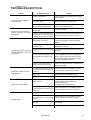
MAC 600/E
user manual
© 1997 - 2000 Martin Professional A/S, Denmark.
All rights reserved. No part of this manual may be
reproduced, in any form or by any means, without
permission in writing from Martin Professional A/S,
Denmark.
Printed in Denmark.
P/N 35000018 Rev. G
section 1
INTRODUCTION
About this manual .................................................................................................................................................... 4
Safety precautions ................................................................................................................................................... 4
section 2
SETUP
Unpacking ................................................................................................................................................................ 5
Installing or changing the lamp ................................................................................................................................ 5
Powering the fixture ................................................................................................................................................. 5
Rigging the fixture in place....................................................................................................................................... 6
Connecting the serial link ......................................................................................................................................... 7
Setting control protocol and address........................................................................................................................ 8
Installing the snoot (optional) ................................................................................................................................... 8
section 3
OPERATION
Martin RS-485 control .............................................................................................................................................. 9
DMX-512 control ...................................................................................................................................................... 9
Lamp ........................................................................................................................................................................ 9
Mechanical effects ................................................................................................................................................. 10
section 4
CONTROL MODULE
Address and protocol selection .............................................................................................................................. 11
Personality settings ................................................................................................................................................ 12
Readouts................................................................................................................................................................ 13
Manual control........................................................................................................................................................ 13
Test sequences...................................................................................................................................................... 14
Utilities.................................................................................................................................................................... 14
section 5
MAINTENANCE AND
BASIC SERVICE OPERATIONS
Removing the printed circuit board ........................................................................................................................ 15
Replacing the printed circuit board......................................................................................................................... 15
Replacing fuses...................................................................................................................................................... 16
Changing the XLR pin-out...................................................................................................................................... 16
Changing lenses .................................................................................................................................................... 16
Cleaning the optical path........................................................................................................................................ 16
Cleaning the fans ................................................................................................................................................... 16
Replacing the lamp ................................................................................................................................................ 17
Optimizing lamp alignment..................................................................................................................................... 17
Changing voltage and frequency settings .............................................................................................................. 17
Updating software .................................................................................................................................................. 19
section 6
APPENDIXES
DMX protocol ......................................................................................................................................................... 20
Error messages...................................................................................................................................................... 22
Troubleshooting .................................................................................................................................................... 23
PCB layout ............................................................................................................................................................. 24
Specifications ......................................................................................................................................................... 25
section 1
I NTR ODUCT I O N
Thank you for selecting the MAC 600 from Martin. This intelligent moving-head Fresnel color changer is fast, quiet, and reliable. It delivers exceptionally bright light that instantly snaps or smoothly fades to virtually any color, at any intensity, anywhere on stage.
About this manual
This manual covers the MAC 600 with magnetic ballast and the MAC 600 Ewith electronic ballast. “MAC 600/E” is used to
refer to both models when describing common features or procedures.
This manual describes the features of software version 2.3. The latest MAC 600/E software and documentation are available
from the Service and Support area of the Martin web site at http://www.martin.dk.
Safety precautions
This product is for professional use only. It is not for household use.
This product presents risks of lethal or severe injury due to fire and heat, electric shock, ultraviolet radiation, lamp explosion,
and falls. 5HDGWKLVPDQXDO before powering or installing the fixture, follow the safety precautions listed below and observe
all warnings in this manual and printed on the fixture. If you have questions about how to operate the fixture safely, please
contact your Martin dealer or call the Martin 24-hour service hotline at +45 70 200 201.
To p r o t e c t y o u r s e l f a n d o t h e r s f r o m e l e c t r i c s h o c k
•
•
•
•
•
Disconnect the fixture from AC power before removing or installing the lamp, fuses, or any part, and when not in use.
Always ground (earth) the fixture electrically.
Use only a source of AC power that complies with local building and electrical codes and has both overload and groundfault protection.
Do not expose the fixture to rain or moisture.
Refer any service operation not described in this manual to a qualified technician.
To p r o t e c t y o u r s e l f a n d o t h e r s f r o m U V r a d i a t i o n a n d l a m p e x p l o s i o n
•
•
•
•
Never operate the fixture with missing or damaged lenses and/or covers.
When replacing the lamp, allow the fixture to cool for at least 15 minutes before opening the fixture or removing the
lamp. Protect your hands and eyes with gloves and safety glasses.
Do not stare directly into the light. Never look at an exposed lamp while it is lit.
Replace the lamp before usage exceeds the maximum service life, or if the lamp is defective or worn out.
To p r o t e c t y o u r s e l f a n d o t h e r s f r o m b u r n s a n d f i r e
•
•
•
•
•
•
•
•
Never bypass the thermostatic switch or fuses. Always replace defective fuses with ones of the specified type and rating.
Keep all combustible materials (for example fabric, wood, paper) at least 1.0 meter (39 inches) away from the fixture.
Keep flammable materials well away from the fixture.
Do not illuminate surfaces within 1.0 meter (39 inches) of the fixture.
Provide a minimum clearance of 0.1 meters (4 inches) around fans and air vents.
Never place filters or other materials over the lens.
Allow the fixture to cool for at least 5 minutes before handling.
Do not modify the fixture or install other than genuine Martin parts.
Do not operate the fixture if the ambient temperature (Ta) exceeds 40° C (104° F).
To p r o t e c t y o u r s e l f a n d o t h e r s f r o m i n j u r y d u e t o f a l l s
•
•
•
•
4
When suspending the fixture, verify that the structure can hold at least 10 times the weight of all installed devices.
Verify that all external covers and rigging hardware are securely fastened and use an approved means of secondary
attachment such as a safety cable.
Block access below the work area whenever installing or removing the fixture.
Do not lift the fixture by its head.
0$&(
section 2
SETU P
This section describes the simple steps required to prepare the MAC 600/E for operation.
Unpacking
The MAC 600/Epackage includes:
•
2 Fast-Lock Omega clamp brackets
•
5-meter XLR-XLR control cable
•
Light snoot
•
User manual
The packing material is carefully designed to protect the fixture during shipment - always use it or a custom MAC 500/600
flight case to transport the fixture.
Installing or changing the lamp
WARNING!
Disconnect the fixture from AC power before proceeding. Always wear safety goggles to protect your eyes and allow a hot lamp to cool for at least 15 minutes
before removing it from the fixture.
The MAC 600/E works with the Philips MSR-575/2 and MSD-575, and the Osram HSR-575/2. ,QVWDOOLQJDQ\RWKHUODPSPD\
GDPDJHWKHIL[WXUHThe lamp holder is pre-adjusted at the factory; precise alignment may be necessary due to slight variations
between lamps. The procedure is described on page 17.
1.
The MAC 600/E must be cool and isolated from AC power. Remove the 2 thumbscrews securing the
lamp-socket assembly to the rear of the head. Pull out the lamp-socket assembly.
2.
If changing the lamp, remove the old lamp from the socket.
3.
Holding the new lamp by its ceramic base (do not touch the glass), insert it firmly and squarely into the
lamp socket.
4.
Clean the glass bulb with the cloth supplied with the lamp, particularly if your fingers touch the glass. A
clean, lint-free cloth wetted with alcohol may also be used.
5.
Keep the lamp wire between the fins as you insert the lamp-socket assembly into the head. Turn the
assembly counterclockwise to align the holes with the spacer nuts. Replace the thumbscrews and
tighten them by hand.
6.
Before striking the lamp, reset the RLAH and RLST counters under the TIME menu to track lamp hours
and lamp strikes. See page 13.
Powering the fixture
Check voltage and frequency settings
The settings must match the local AC power supply. These settings are printed on the serial number label on the base. If the
settings do not match the local conditions, then the ballast and/or transformer must be rewired. See section 5 for details.
User Manual
5
WARNING!
For protection from dangerous electric shock, the fixture must be grounded
(earthed). The AC mains supply shall be fitted with a fuse or circuit breaker and
ground-fault protection.
Install a plug on the power cord
You may need to install a cord cap that fits your supply on the power cable. A 3-prong grounding-type plug must be installed
following the manufacturer’s instructions. Connect the wires to the pins as listed below. Note: The table shows some possible
pin identification schemes; if the pins are not clearly identified, or if you have any doubts about proper installation, consult a
qualified electrician.
Wire Color
Pin
Symbol
Screw (US)
brown
live
“L”
yellow or brass
blue
neutral
“N”
silver
yellow/green
ground
green
Connect the MAC 600/E directly to AC power. 'RQRWFRQQHFWLWWRDGLPPHUV\VWHPGRLQJVRPD\GDPDJHWKHIL[WXUH To
apply power, set the power switch on the base to the “I” position.
Rigging the fixture in place
WARNING!
Use 2 clamps to rig the fixture. Lock each clamp with both 1/4-turn fasteners. The
fasteners are locked only when turned fully clockwise.
Attach an approved safety cable to the base.
The MAC 600/E can be placed directly on the stage floor or rigged in any orientation on a truss. The integrated Fast-Lock system enables quick and easy fastening of the clamp adapters in 4 different positions as shown below.
safety wire
attachment point
arrow points to front
(neutral pan)
6
1.
Verify that the rigging clamps (not included) are undamaged and can bear at least 10 times the weight
of the fixture. Bolt the clamps securely to the clamp brackets with a grade 8.8 (minimum) M12 bolt and
lock nut, or as recommended by the clamp manufacturer.
2.
Tip the MAC 600/E on its side or install the clamps while the fixture is in the flight case.
3.
Align a clamp with 2 mounting points. Insert the fasteners into the base and turn both levers a full 1/4turn clockwise to lock. Install the second clamp.
4.
Verify that the structure can bear at least 10 times the weight of all installed fixtures, clamps, cables,
auxiliary equipment, etc.
5.
Working from a stable platform, hang the fixture on the truss. The front is indicated by an arrow on the base.
6.
Install a safety wire that can bear at least 10 times the weight of the fixture. The attachment point is
designed to fit a caribiner clamp. Never use the carrying handles for secondary attachment.
0$&(
7.
Tighten the rigging clamps securely to the structure.
8.
Verify that there are no combustible materials or surfaces to be illuminated within 1 meter of the fixture,
and that there are no flammable materials nearby.
Connecting the serial link
Tips for building a serial link
1.
Use shielded twisted-pair cable designed for RS-485 devices. Standard microphone cable cannot
transmit control data reliably over long runs; use only cable designed for RS-485 applications. 24 AWG
cable is suitable for runs up to 300 meters (1000 ft). Heavier gauge cable and/or an amplifier is recommended for longer runs.
2.
Never use a “Y” connector to split the link. To split the serial link into branches use a splitter such
as the Martin 4-Channel Opto-Isolated RS-485 Splitter/Amplifier.
3.
Do not overload the link. Up to 32 devices may be connected on a serial link.
4.
Terminate the link by installing a termination plug in the output socket of the last fixture on the link.
The termination plug, which is simply a male XLR connector with a 120 ohm, 0.25 watt resistor soldered between pins 2 and 3, “soaks up” the control signal so it does not reflect back down the link and
cause interference. If a splitter is used, terminate each branch of the link.
Connecting fixtures
The MAC 600/E has locking 3-pin data input and output sockets that can be configured for use with either DMX or Martin
Protocol controllers. 7KHGHIDXOWSLQRXWLVFRQILJXUHGWRWKH'0;VWDQGDUG, i.e., pin 1 to shield, pin 2 to signal (-) and
pin 3 to signal (+).
3-pin to 3-pin
Phase-Reversing
Cable
3-pin to 5-pin
Phase-Reversing
Cable
5-pin to 3-pin
Phase-Reversing
Cable
5-pin to 3-pin
Straight
Cable
3-pin to 5-pin
Straight
Cable
Connections
Connections
Connections
Connections
Connections
Male
Female
Male
Female
Male
Female
Male
Female
Male
Female
1
2
3
1
2
3
1
2
3
1
2
3
4
5
1
2
3
4
5
1
2
3
1
2
3
4
5
1
2
3
1
2
3
1
2
3
4
5
P/N 11820006
1.
P/N 11820002
P/N 11820003
P/N 11820005
P/N 11820004
Connect the controller’s data output to the MAC 600/E’s data input. For a
•
•
•
DMX controller with 5-pin output: use a cable with 5-pin male and 3-pin female connectors such as
P/N 11820005. Pins 4 and 5 are not used.
DMX controller with 3-pin output: use a cable with 3-pin male and female connectors such as the one
supplied.
Martin RS-485 Protocol controller: use a phase-reversing cable, such as P/N 11820006, with 3-pin
male and female connectors or reconfigure the XLR output.
2.
Continue the link: connect the output of the fixture closest to the controller to the input of the next fixture. Use a phase-reversing cable when connecting a DMX-standard (pin 3 +) device to a Martin-standard (pin 3 -) device.
3.
Insert a male 120 Ω XLR termination plug in the output of the last fixture on the link.
User Manual
7
Setting control protocol and address
One of the operating modes shown below must be selected. Factors to consider when selecting a mode will depend on your
controller and are discussed in the next section. Maximum flexibility is provided in mode 4.
Each fixture must be assigned its own channels to receive instructions from the controller. The address, also known as the start
channel, is the first channel used. Addresses are independent of the physical link: they may be set in any convenient order.
Two MAC 600/E’s may share the same address; however, they will receive the same instructions and independent control will
not be possible.
Mode
Martin
Movement speed
Vector
Pan/tilt resolution
16 bit
8 bit
16 bit
8 bit
16 bit
2
10
12
12
14
Channels
DMX 1
DMX 2
DMX 3
Tracking
DMX 4
Tracking and/or Vector
1.
Switch on the MAC 600/E.
2.
You may push [MENU] and [ENTER] simultaneously to disable pan and tilt reset. This is handy if you
want to change settings while the MAC 600/E is in a flight case. As the fixture does not run through the
entire reset procedure, error messages will be displayed. This is not a fault with the fixture. The reset
procedure can take 2 - 3 minutes.
3.
Press the [MENU] key once, and then press the [↑] or [↓] keys repeatedly until the display shows
PSET. Press [ENTER] to confirm.
4.
Press [↑] or [↓] until the desired protocol, as shown in the above table, appears on the display. Press
[ENTER] to confirm.
5.
Press [↑] or [↓] repeatedly until the display shows either dAdr or MAdr, depending on whether you
wish to select a DMX address or Martin address, respectively. Press [ENTER] to confirm.
6.
Press [↑] or [↓] repeatedly until the desired address is displayed. Press [ENTER] to confirm.
Press [MENU] to return to the main menu. The address is displayed. Address and protocol settings are saved when the
power is switched off.
Installing the snoot (optional)
1.
Bend the tabs 90°.
2.
Bend the ring into a circle with the tabs on the outside. Weave the end tab through the 3 slots.
3.
Insert the tabs between the 3 pairs of pins between the lens and the head cover.
1
8
2
0$&(
3
section 3
OPER AT I O N
This section describes the MAC 600/E’s controllable features and the options for customizing them for your application.
Option selection is described in the next section.
Martin RS-485 control
The MAC 600/E may be controlled with the Martin 3032 controller. For the fixture to respond, either the protocol setting
(PSET) must be set to Martin (MART) as described in the previous section, or automatic protocol detection (SPEC/AUTO)
must be enabled.
DMX-512 control
Tr a c k i n g m o d e
In tracking mode the speed at which an effect moves is determined by the controller’s fade time. The effect tracks the fade
from one DMX value to another and a digital filter algorithm ensures smooth movement at all fade speeds.
There are 2 selectable tracking algorithms to provide extremely smooth movement with any controller. Algorithm 1 calculates
speed based on the absolute value of DMX changes; it is recommended for use with most controllers. Algorithm 2 uses the
real value of DMX changes to calculate speed and may provide smoother movement if the controller-calculated DMX values
are uneven.
The number of samples, that is, changes in DMX values, used by both algorithms to calculate speed is selectable between a
level of 1 to 10. The ideal setting will vary from controller to controller - experiment for best results. Increasing the number of
samples makes movement less responsive to sudden DMX changes and smoother as a result.
Ve c t o r m o d e
In vector mode, 2 speed channels provide a way to control the effects’ speed with controllers that do not have programmable
fade times. This mode may result in smoother movement when using a controller with a slow or irregular refresh rate. Vector
mode also provides a “blackout” speed and overrides of the pan/tilt speed (PTSP), shortcut (SCUT), and studio mode (MOdE)
menu settings.
In vector mode the controller fade time should be set to 0, i.e., the position bumps from one value to the next. However, controller fade times can be enabled by setting the speed channel between 0 and 2.
8-bit versus 16-bit pan/tilt resolution
With 8-bit pan/tilt resolution, the pan and tilt are divided into 256 equal increments. Finer position control and smoother
movement is provided in the 16-bit modes.
Lamp
The MAC 600/E can be set to automatically strike within 90 seconds of being powered on by setting Automatic Lamp On
(SPEC/ALON) to ON. A delay determined by the fixture address prevents all lamps from striking at the same time.
If Automatic Lamp On is set to off, the default, the lamp remains off until a “lamp on” command is sent from the controller.
Note: A peak of electric current that can be many times the operating current is drawn for an instant when striking the lamp.
Striking many lamps at once may cause a voltage drop large enough to prevent lamps from striking or trip the main circuit
breaker. Avoid this by programming a “lamp on” sequence that strikes lamps one at a time at 5 second intervals.
Power to the lamp can be turned off from the controller if the DMX Lamp Off (SPEC/dLOF) feature is enabled. There is a
combination of DMX values that allows you to turn off the lamp even if this feature is disabled. %HFDUHIXO: it is not possible to
strike the lamp within 8 minutes of having switched it off. The MAC 600/E will store a “lamp on” command and strike the
lamp automatically when the 8 minutes have elapsed.
With the MAC 600 E, lamp power falls to 400 watts for cooler operation and longer lamp life when the shutter is closed for 10
seconds. Power instantly returns to full when the shutter opens. Reduced-power mode with the shutter open can be forced by
setting channel 1 to a DMX value from 116 to 122.
User Manual
9
Mechanical effects
All mechanical effects are reset to a “home” position when the fixture is powered up. The fixture can also be reset via DMX if
DMX reset (SPEC/dRES) is enabled. There is also a combination of DMX values that allows you to reset the MAC 600/E
even if this feature is disabled; see the DMX protocol for details.
An on-the-fly position correction system automatically corrects the position of the effect wheels. This feature can be disabled
by setting effects feedback (SPEC/EFFb) to OFF.
General operation may be optimized for speed or quietness with the studio mode setting (MOdE).
Pan and tilt
The moving head can be panned 440° and tilted 306°. The middle of the pan range is perpendicular to the front of the fixture,
as indicated by the arrow on the base. Movement may be optimized for speed by setting the pan/tilt speed (PTSP) personality
to FAST, or for smoothness by setting it to NORM. The setting may be overridden on the speed channel in vector mode.
Movement is disabled if lamp feedback is lost - indicating a blown lamp - to prevent possible damage or injury due to glass
fragments.
Setting the movement speed to “blackout” in vector mode causes the shutter to black out the light while the head is moving.
The pan and tilt DMX channels can be inverted and/or swapped for convenience using the pan/tilt (PATI) menu.
Color wheel
The color wheel has red, green, and blue dichroic color filters plus a 5600K to 3400K color correction filter and open white.
The wheel can be scrolled, allowing for split color effects, snapped to fixed positions, and continuously rotated in both directions at different speeds.
The Shortcuts (SPEC/SCUT) setting determines whether the wheel takes the shortest path to the next position or turns in one
direction only. The setting may be overridden on the speed channel in vector mode.
Setting the color speed to “blackout” in vector mode causes the shutter to black out the light while the wheel moves.
CMY subtractive color mixing
The CMY color mixing system is based on three graduated dichroic color filters: cyan, magenta, and yellow. Each color can
be added from 0 to 100%. A very wide range of colors may be achieved by varying the amount of each color. Since the CMY
system is subtractive, mixing 3 colors together results in a loss of light. For maximum brightness, mix 2 colors at a time. Three
speed random CMY color mixing is available at the top of channel 6.
The Shortcuts (SPEC/SCUT) setting determines whether the wheels take the shortest path to the next position or turn in one
direction only. The setting may be overridden on the speed channel in vector mode.
Beam shapers and frost
Two beam shapers allow you to widen and flatten the beam. Beam shaper 1 rotates 180° and beam shaper 2 rotates 90°. They
may be combined to drag the beam horizontally and vertically to increase the beam size.
A frost filter on the same wheel as beam shaper 2 softens the beam.
Dimmer
The mechanical dimmer provides smooth, high-resolution 100 percent dimming.
Shutter
The high-speed mechanical shutter opens and closes the light instantly. Light can be flashed at up to 8 Hz and there is a DMXcallable random strobe function.
If the auto shutter function (SPEC/ASHT) is enabled, the shutter, which is faster than the dimmer, automatically closes when
the dimmer receives a command to close “instantly,” to provide faster blackouts.
10
0$&(
section 4
C ONTRO L M O DUL E
The 4-digit LED control panel on the side of the MAC 600/E allows you to set the address and personalities, read lamp hours
and other information, calibrate effects, control the fixture manually, and run a test routine. Most of these functions may be
performed remotely via the serial link with a Martin MPBB1 or MP-2 uploader
The display can be flipped for easy reading by pressing the [↑] and [↓]keys simultaneously. The intensity is adjustable and the
display can be set to go out 2 minutes after the last key-press.
The DMX or Martin address, depending on the protocol setting, and any error messages are displayed when the MAC 600/E is
turned on. To enter the menu, press [MENU]. Use the [↑] and [↓]keys to move within the menu. To select a function or submenu, press[ENTER]. To escape a function or menu, press [MENU].
Address/
Messages
PSET
dAdr
MAdr
TIME
AdJ
CAL
PATI
MAN
dMXL
Po H
RST
P OF
SWAP
RST
RPoH
L ON
T OF
PINV
LA H
LoFF
d OF
TINV
RLAH
HEAd
LSTR
ALL
dIM
CYAN
MAG
YEL
COL
BS1
BS2
SHUT
Y OF
RLST
PATI
TSEQ
PTSP
EFSP
MOdE
VER
SPEC
STCO
CPU
dISP
L ON
CH 0
FEbA
dINT
LoFF
....
dISP
dLoF
C OF
SHUT
CH13
M OF
dIM
ALON
CYAN
FEbA
dRES
MAG
dFSE
YEL
FACT
CUS1
CUS2
CUS3
COL
BS1
dFOF
BS2
AUTO
PAN
UPLd
TILT
ASHT
TEMP
bASE
HEAd
FAN
PCbT
SCUT
FTST
EFFb
TRAC
MOdE
CAL
ETYP
Address and protocol selection
3URWRFROVHOHFWLRQPSET Switch between MART, DMX1, DMX2, DMX3,or DMX4 to enable Martin mode or DMX mode
1, 2, 3, or 4.
'0;DGGUHVVdAdr Set the DMX address between channel 1 and 512.
Martin address (MAdr): Set the Martin address between channel 1 and 31.
User Manual
11
Personality settings
Personality
Pan/tilt speed
Pan/tilt swap
Pan inverse
Tilt inverse
Tracking algorithm
Path
DMX lamp off
SPEC/dLOF
Shortcuts
SPEC/SCUT
Electronic ballast
type
Normal pan and tilt control.
ON
Reverse DMX pan control, right Æ left.
OFF
Normal pan control, left Æ right.
ON
Reverse DMX tilt control, down Æ up.
OFF
Normal tilt control, up Æ down
MOd1
Absolute delta value algorithm (for most controllers)
MOd2
Real delta value algorithm
1-10
Tracking samples. Increase if pan/tilt is not smooth.
FAST
Normal, full speed operation.
SAFE
Reduced speed operation (mainly for early models).
ON
Display stays on.
OFF
Display goes out 2 minutes after last key press.
10- 100
Adjust display intensity.
ON
Enable DMX lamp off command.
OFF
Disable DMX lamp off command.*
ON
Enable DMX reset command.
OFF
Disable DMX reset command.*
ON
Lamp strikes automatically within 90 seconds of power on.
OFF
Strike lamp from controller.
ON
Enable automatic protocol detection.
OFF
Disable automatic protocol detection.
ON
Effect wheels turn the shortest direction.*
OFF
Effect wheels always turn same direction.*
ON
Shutter “helps” dimmer black out.
OFF
Shutter not affected by dimmer commands.
NORM
Optimize effects for speed.*
STUd
Optimize effects for silence.*
ON
Enable pan/tilt position correction system.
OFF
Disable pan/tilt feedback. Setting not saved.
ON
Enable feedback on effect wheels.
OFF
Disable feedback on effect wheels.
REG
Enable automatic fan speed regulation.
FULL
Set fan speed to full.
SCHI
Select Schiederwerk ballast (MAC 600 E's after S/N
4020700000)
SPEC/ALON
SPEC/AUTO
Fan speed
OFF
SPEC/dRES
Automatic protocol
detection
Effects feedback
Map DMX pan control to tilt channel and vice versa.
SPEC/dISP
SPEC/dINT
Pan/tilt feedback
ON
SPEC/TRAC/MOdE
Display intensity
Studio mode
Optimize movement for smoothness.*
PATI/TINV
EFSP
Automatic shutter
NORM
PATI/PINV
Effects speed
Automatic lamp on
Optimize movement for speed.*
PATI/SWAP
SPEC/TRAC/CAL
DMX reset
SPEC/ASHT
MOdE
SPEC/FEbA
SPEC/EFFb
SPEC/FAN
SPEC/ETYP
MITR
12
Effect (Default settings shaded.)
FAST
PTSP
Tracking samples
Display on/off
Options
Select Mitronic ballast (MAC 600 E’s with date-based S/N or
before S/N 4020700000)
* Setting may be overridden via DMX. See the protocol for details.
0$&(
Readouts
U s a g e r e a d o u t s ( TIME)
Read the total number of power-on hours (Po H), power-on hours since last reset (RPoH), total lamp hours (LA H), lamp
hours since last reset (RLAH), total number of lamp strikes (LSTR), and the number of lamp strikes since last reset (RLST).
The resettable counters may be used to track overall usage and lamp life. To reset to zero, display the readout and then press
[↑] for 5 seconds.
D M X v a l u e r e a d o u t s ( dMXL)
Read the DMX start code (STCO) and DMX values received for each channel. This is an easy way to check that the start code
is 0 and that the fixture is receiving the expected commands.
If the fixture is set to a DMX mode where some or all of the channels between 10 and 13 are not used, the readout on these
channels will be N/A. Note: the channel number is 1 less in the readout than it is in the DMX protocol.
S o f t w a r e v e r s i o n r e a d o u t s ( VER)
Read the version number of the CPU software (CPU), pan/tilt feedback circuit (FEbA), and display module software
(dISP). The CPU software version is also displayed for a moment at power up.
T e m p e r a t u r e r e a d o u t s ( SPEC/ TEMP)
Read temperature in the base (bASE) and head (HEAd) in Celsius. Temperatures below 25° C are shown as -25; temperatures above 100° C are shown as +100.
Thetemperature sensors are calibrated at the factory and adjustment should not be necessary. The following procedure calibrates the sensors if they give no or faulty readings.
1.
Allow the unit to cool to room temperature (powered off for at least 4 hours).
2.
Measure the room temperature in Celsius. (To convert F° to C°, subtract 32° and then multiply by
0.555.)
3.
Power up the unit and allow it to reset.
4.
Press the [MENU] and [↓] keys at the same time and hold them for 3 seconds until “25” shows in the
display.
5.
Press the [↑] and [↓] keys until the display shows the temperature measured.
6.
Press [ENTER] to save the setting.
Manual control
M a n u a l c o n t r o l ( M A N)
The manual control menu permits you to do the following without a controller:
•
reset the fixture (R S T )
•
turn the lamp on and off (L O N , L o F F )
•
open, close, and strobe the shutter at 3 speeds (S H U T )
•
control the dimmer (d I M )
•
control the CMY wheels (C Y A N , Y E L , M A G )
•
move the color wheel to each position (COL)
•
control both beam shapers (BS1, BS2)
•
control pan and tilt (P A N , T I L T )
User Manual
13
A d j u s t m e n t ( AdJ)
The adjustment menu provides manual control for making mechanical adjustments. These should only be performed by a
qualified technician. The menu provides functions to reset the fixture (R S T ), turn on and off the lamp (L O N , L o F F ), control all effects in the head (HEAd), and move the head to the home and extreme positions (P A T I ). The H E A d submenu
contains functions to:
•
•
move ALL effects to the OPEN, SPOS (sensor position), and APOS (adjustment position - requires special tool).
move each effect individually to the open, sensor, and adjustment positions. The shutter has a closed position instead of
a sensor position.
Test sequences
Te s t s e q u e n c e ( TSEQ)
Run a general test of all effects.
P r i n t e d c i r c u i t b o a r d t e s t ( SPEC/ PCBT)
3 tests of the circuit board for service use.
F a c t o r y t e s t ( S P E C / F T S T)
An effects test (W T S T ), a movement test (M T S T ), and a sensor test (S T S T ) used for factory quality control. The sensor
test includes programs for testing sensors on the effect wheels.
Utilities
Calibration (CAL)
The calibration menu allows you to adjust the effects to achieve total uniformity between fixtures: it is not a substitute for
mechanical adjustment. Pan (P OF), tilt (T OF), dimmer (d OF), cyan (C OF), magenta (M OF), and yellow (Y OF)
may be selected and adjusted from 1 to 255 with the arrow keys. Press [ENTER] to save the calibration.
R e s e t d e f a u l t o f f s e t s ( SPEC/dFOF)
Reset all calibrations to their factory defaults. Select d F O F and press [ENTER] when S U R E is displayed, or press [MENU]
to escape.
R e s e t d e f a u l t p e r s o n a l i t y s e t t i n g s ( SPEC/ dFSE/ FACT)
Return all personality settings (not calibrations) to their factory defaults. Select F A C T and press [ENTER] when L O A D is
displayed.
C u s t o m c o n f i g u r a t i o n s ( S P E C / d F S E/ C U S 1, C U S 2 , C U S 3)
Save and load 3 sets of custom configurations. To save a custom configuration, adjust the settings as desired, go to C U S 1 ,
C U S 2 , or C U S 3 and press [ENTER] when S A V E is displayed. To load a custom setting, select it and press [ENTER]
when L O A D is displayed.
U p l o a d m o d e ( U P L d)
Upload mode prepares the MAC 600/E to receive control software. It is normally engaged automatically by the upload device.
In certain circumstances, however, you may have to set upload mode manually as described under “Updating software” on
page 19.
14
0$&(
section 5
MAINTENANCE AND
BASIC SERVICE OPERATIONS
The MAC 600/E requires regular maintenance to keep performing at its optimum. The maintenance schedule will be dependent upon the operating environment. Dirty lenses and filters reduce the light’s brightness. Cooling fans covered by dust may
cause overheating, thus causing the thermostat to cut out the lamp intermittently. This section takes you through the general
maintenance procedures and describes some basic service operations.
WARNING!
All service procedures that require removing covers shall be performed
by a qualified technician.
Disconnect from AC power before removing any cover or part.
Removing the printed circuit board
1.
Disconnect the fixture from AC power.
2.
Remove the flat plate from the top of the front side of the base. Do not remove the curved side plates.
3.
Unplug the white plastic wire connectors from the top of the printed circuit board. To unplug a connector, hold the plastic connector - never pull the wires - and pull it straight off the pins.
4.
Grasp the black pins on either end of the circuit board and gently pull it out. You may have to guide
some wires past the motor housing. Be careful not to knock the copper heat sinks.
Replacing the printed circuit board
PL201 display
PL202 OPTO1
PL203 OPTO2
PL302 not used
PL303 4-pin fan
PL304 2-pin fan
PL301 not used
User Manual
PL401 DIM
PL411 CYAN
PL421 MAG
PL431 YELL
PL441 COLOR
Replace the top cover.
PL501 BEAM1
3.
PL511 BEAM2
Reconnect the wire connectors. Each connector (except for the 2 fan
connectors and the control module connector) is labelled. Fit the female
over the male with the “rails” on the female connector over the “tongue”
on the male connector. Your MAC 600/E may or may not have unused
connectors PL301 and PL302. Starting from the end with the copper heat sinks, the connection order
is:
PL521 SHUT
2.
PL531 PAN
Gently put the circuit board back into the base. You may have to guide
some wires past the motor housing. Push the black pins down to lock the
board in place.
PL551 TILT
1.
15
Replacing fuses
The main fuse is located above the XLR output and is replaced by unscrewing the holder with a screwdriver or small coin. The
secondary fuses are located on the printed circuit board and are replaced as follows.
1.
Remove the printed circuit board as described above.
2.
Locate and replace the defective fuse with one of the same rating. The fuses are shown on the PCB
layout diagram on page 24 as F601, F602, and F603. Their values are listed on page 25.
3.
Replace the printed circuit board.
Changing the XLR pin-out
1.
2.
3.
Remove the printed circuit board as
described above.
2
-
2
-
Position the jumpers for the desired
XLR pin-out as shown.
+
3
+
3
Replace the printed circuit board.
Martin pin-out
DMX pin-out
Changing lenses
WARNING
Attach the safety wire to the front head section.
18° and 65° field angle options are available for the MAC 600/E. (See “Accessories” on page 26.) The lens is mounted on a
snap-lock “lens hood” or front section that attaches easily to the head. Simply release the snap locks and unhook the safety
wire to remove the standard lens front. Hook the safety wire to the same location on the optional front and snap the locks
closed.
IMPORTANT
The long front (18° option) does not fit in some flight cases.
The 18° front is longer than the standard front; the MAC 600/E fitted with this option fits only in flight cases produced after
September, 1997. These can be identified by the outside measurements: 894 mm (35.2") from bottom to top, including wheels.
Older flight cases measure 860 mm (34") from bottom to top, including wheels, on the outside.
Verify that the flight case is of the newer type before shipping MAC 600/Es fitted with the 18° long front.
Cleaning the optical path
Cleaning and servicing components in the head is best left to qualified Martin technicians.
To access the optical components, remove the head cover. Remember to attach the internal safety cable when reassembling the
head.
Be very careful if you decide to clean the optical components. The colored surface on the dichroic filters is achieved by means
of special multi-layer coatings and even small scratches in these might be visible. Residues left from cleaning fluids can bake
onto and ruin the component.
Wash dirty lenses and filters with isopropyl alcohol. Rinse with distilled water: mixing the water with a small amount of wetting agent such as Kodak Photoflo will help prevent streaking and spotting. Dry with a clean, soft and lint-free cloth or blow
dry with compressed air. A generous amount of regular window glass cleaner may also be used, but no residues may remain.
Cleaning the fans
To ensure proper cooling of the fixture it is important that the fans are free of dust. Clean the fans with a vacuum or damp cloth
if they are dirty.
16
0$&(
Replacing the lamp
The risk of lamp explosion increases with lamp hours as the quartz envelope gradually weakens. It is recommended that lamp
usage not exceed 125 percent of the lamp’s rated average life.
The procedure for installing the lamp is described on page 5. After installing the lamp, reset the RLAH and RLST counters
under the TIME menu as described page 13.
Optimizing lamp alignment
The lamp alignment is set at the factory. If, however, the distribution of light does not appear even, lamp alignment can be
adjusted.
1.
Switch on the MAC 600/E and allow it to reset.
2.
Using either a controller or the control module, turn on the lamp and aim the light towards a flat surface.
3.
Center the hot-spot (the brightest part of the beam) using the 3 allen-head (3 mm) adjustment screws.
Turn one screw at a time to drag the hot-spot diagonally across the projected image. If you cannot
detect a hot-spot, adjust the lamp until the light is even.
4.
To reduce a hot-spot, pull the lamp in by turning all three screws clockwise 1/4-turn at a time until the
light is evenly distributed.
5.
If the light is brighter around the edge than it is in the center, or if light output is low, the lamp is too far
back in the reflector. “Push” the lamp out by turning the screws counterclockwise 1/4-turn at a time
until the light is bright and evenly distributed.
Changing voltage and frequency settings
7KHYROWDJHDQGIUHTXHQF\VHWWLQJVPXVWPDWFKWKHORFDO$&SRZHUVXSSO\ These settings are printed on the serial number
label on the bottom of the base. Using the wrong setting can cause overheating, fixture damage, and/or poor performance.
MAC 600 (magnetic ballast)
1.
Disconnect the MAC 600 from AC power. Remove the top covers.
2.
Find the correct transformer and ballast terminals for your AC supply in the table below. Consult a
qualified electrician if you do not know the AC frequency and voltage.
AC Supply
Transformer
Magnetic Ballast
Frequency
Voltage
Voltage
Terminal
Setting
Terminal
50 Hz
200-210 V
210 V
4
200 V / 50 Hz
7
50 Hz
210-220 V
210 V
4
230 V / 50 Hz
10
50 Hz
220-235 V
230 V
6
230 V / 50 Hz
10
50 Hz
235-240 V
230 V
6
245 V / 50 Hz
12
50 Hz
240-260 V
250 V
8
245 V / 50 Hz
12
60 HZ
200-217 V
210 V
4
208 V / 60 Hz
4
60 HZ
217-240 V
230 V
6
227 V / 60 Hz
7
3.
Locate the transformer: it is on the left end, near the power switch. Move the BROWN and RED transformer wires to the correct terminal. The terminal number is printed in front of the connection tab.
4.
Locate the magnetic ballast: it is on the opposite end from the transformer, near the control panel.
Move the BROWN ballast wire to the correct terminal. The terminal number is printed in front of the
connection tab.
5.
Replace the top covers before applying power.
User Manual
17
MAC 600 E (electronic ballast)
The electronic EDOODVW works at any voltage between 100 and 250 volts, and at any frequency between 50 and 60 Hz.
1.
Disconnect the fixture from AC power. Remove the top covers.
2.
Tap the transformer for the local supply voltage as shown below.
3.
Verify that the primary fuse, which is located near the power switch, is correct for the voltage setting.
Use a T 6.3 A fuse when the transformer is set at 200, 210, 220, 230, or 240 V. Use a T 10 A fuse
when it is set at 100, 110, or 120 V.
4.
Replace the top covers before applying power.
9
5
5
brown
red
3
blue
blue
1
brown
red
blue
4 100 V
blue
blue
brown
red
7
7
brown
red
8
6
5
5
3
3
blue
blue
7
9
4 120 V
9
8
8
9
7
6
5
8
6
5
4 210 V
4 220 V
4 230 V
4 240 V
3
3
3
3
1
blue
blue
1
blue
blue
1
blue
blue
MAC 600 E Transformer Settings
18
1
brown
red
7
5
9
4 200 V
blue
blue
1
9
6
8
3
brown
red
7
5
8
6
4 110 V
1
black
black
9
brown
red
6
blue
blue
8
black
blue
7
6
black
8
blue
7
6
brown
red
black
black
black
black
0$&(
1
9
Updating software
The latest MAC 600/E software is available from your Martin dealer and the Martin Professional web site. Be sure to read the
upgrade notes included with the software.
Software updates are installed using a Martin MPBB1, MP-2, or a LightJockey 4064 DMX interface card. The procedure is
found in the upload device’s user manual and, when using the 4064 card, the Martin Software Uploader program’s online help
file.
Normal upload
The uploader is connected to the fixture just like a controller. Under normal conditions, software can be installed from a
remote location - there is no need to set the MAC 600/E to boot mode. Please refer to the uploader manual for instructions.
Boot mode upload
If the data is corrupted during transmission a check-sum error (CSER) will occur and after 15 seconds the fixture will automatically switch over to boot mode (UPLd) and be ready for a boot mode upload.
If a software upload to the MAC 600/E is interrupted, the fixture must be powered off for at least 10 seconds before a new
upload can be attempted. When powered on, a check-sum error will occur and it will automatically go into boot mode, ready
for a second upload attempt. Select boot mode upload on the upload device.
1.
Remove the printed circuit board as described above. It
may not be necessary to unplug the connectors.
PL121
1
boot setting
PL121
INIT
If the control panel does not work, boot mode can be engaged by moving jumper PL121 on the main circuit board to pins 1 and 2 as follows.
INIT
If there is no functional software in the MAC 600/E memory, the fixture must be set to boot mode manually before starting the
upload. If the control panel works, select UPLd from the SPEC menu and confirm when SURE is displayed by pressing
[ENTER].
1
normal setting
2.
Position jumper PL121 to boot mode (INIT) as shown
above. See also the circuit board layout diagram on
page 24.
3.
Plug in any unplugged connectors, apply power to the MAC 600/E, and proceed with the upload.
4.
After the upload, disconnect the fixture from the electricity, move the jumper back to the normal setting,
and replace the circuit board.
User Manual
19
appendix a
DMX PRO T O CO L
DMX channel
DMX1
DMX2
DMX3
Start code = 0
DMX4
1
Note:
Lamp Off is allowed with SPEC/dLoF
set to ON, or with SPEC/dLoF set to
OFF and cyan, magenta and yellow
set between 230 and 232.
Reset is allowed with SPEC/dRES
set to ON, or with SPEC/dRES set to
OFF and cyan, magenta and yellow
set between 230 and 232.
2
3
4
5
6
7
8
9
-
20
10
-
10
Value
Percent
0 - 19
20 - 49
50 - 112
113 - 115
116 - 122
123 - 127
128 - 147
148 - 167
168 - 187
188 - 207
208 - 217
218 - 227
228 - 237
238 - 247
248 - 255
0-7
8 - 19
20 - 44
44 - 45
45 - 48
48 - 50
50 - 58
58 - 65
66 - 73
74 - 81
82 - 85
85 - 89
89 - 93
93 - 97
97 - 100
0 - 255
0 - 100
0-255
0 - 100
0-255
0 - 100
0-255
0 - 100
0 - 40
40 - 80
80 - 120
120 - 160
0 - 16
16 - 31
31 - 47
47 - 63
Function
6KXWWHU6WUREH5HVHW/DPS2Q2II
Shutter closed
Shutter open
Strobe on (fast->slow)
Shutter closed
Shutter open, reduced lamp power (MAC 600 E)
Shutter closed
Random Strobe Fast
Random Strobe Medium
Random Strobe Slow
Shutter closed
Reset Fixture
Shutter closed
Lamp power on
Shutter closed
Lamp power off 1RWH: T ≥ 5 seconds
,QWHQVLW\
0 Æ 100%
&\DQ
White Æ Cyan
0DJHQWD
White Æ Magenta
<HOORZ
White Æ Yellow
&RORU:KHHO
Scroll
White Æ Color 1
Color 1 Æ Color 2
Color 2 Æ Color 3
Color 3 Æ Color 4
161 - 165
166 - 170
171 - 175
176 - 180
181 - 185
63 - 65
65 - 67
67 - 69
69 - 71
71 - 73
Fixed Colors
Color 4
Color 3
Color 2
Color 1
White
186 - 214
215 - 243
73 - 84
84 - 95
Continuous Rotation
CW, fast Æ slow
CCW, slow Æ fast
244 - 247
248 - 251
252 - 255
96 - 97
97 - 98
99 - 100
0
1 - 255
0
0 - 100
0-2
3 - 170
171 - 255
0-1
1 - 67
67 - 100
0 - 255
0 - 100
0 - 255
0 - 100
Random CMY Color
Random color, fast
Random color, medium
Random color, slow
%HDP6KDSHU
Open
Beam shaper left Æ right
%HDP6KDSHU
Open
Beam shaper left Æ right
Frost
3DQ&RDUVHELW06%
Left Æ right (128 = neutral)
3DQ)LQHELW/6%
Left Æ right
0$&(
DMX channel
Start code = 0
DMX1
DMX2
DMX3
DMX4
10
11
10
11
-
12
-
12
-
-
-
-
11
12
13
Value
Percent
0 - 255
0 - 100
0 - 255
0 - 100
0-2
3 - 245
246 - 248
249 - 251
252 - 255
0-1
1 - 96
96 - 97
98 - 98
99 - 100
0-2
3 - 239
240 - 242
243 - 245
246 - 248
249 - 251
252 - 255
0-1
1 - 94
94 - 95
95 - 96
96 - 97
98 - 98
99 - 100
Function
7LOW&RDUVHELW06%
Up Æ down (128 = neutral)
7LOW)LQHELW/6%
Up Æ down
6SHHG3DQ7LOW
Tracking
Fast Æ slow
Tracking, normal speed (override PTSP FAST)
Tracking, fast speed (override PTSP NORM)
Blackout
6SHHG'LPPHU&0<%P6KDSHU
Tracking
Fast Æ slow
Tracking, MOdE = NORM (studio mode off)
Tracking, MOdE = STUd (studio mode on)
Tracking, SCUT = OFF (shortcuts off)
Tracking, SCUT = ON (shortcuts on)
Fast
0-2
3 - 239
240 - 242
243 - 245
246 - 248
249 - 251
252 - 255
0-1
1 - 94
94 - 95
95 - 96
96 - 97
98 - 98
99 - 100
Speed: Color, Beam Shaper 2
Tracking
Fast Æ slow
Tracking, MOdE = NORM (studio mode off)
Tracking, MOdE = STUd (studio mode on)
Tracking, SCUT = OFF (shortcuts off)
Tracking, SCUT = ON (shortcuts on)
Blackout
14
User Manual
21
appendix b
E RROR M E S S AG E S
Display readout
Appears if...
What to do
... automatic protocol detection is
enabled but the protocol (Martin/DMX)
cannot be determined because there is
no control data.
•
Verify that the controller is
sending and the serial link is
properly connected.
•
LERR (Lamp error)
.... the lamp doesn’t ignite within 10 minutes of receiving the ‘Lamp ON’ command. Likely reasons are a missing or
defective lamp, or insufficient AC voltage.
Check the lamp and check that
the mains setting of the fixture
matches the mains supply.
MERR (Memory error)
...the EEPROM memory cannot be read.
•
Contact Martin service personnel for assistance.
CSER (Check-sum error)
...a software upload is not successful
•
Upload software again, see
page 19.
•
Check fuses on motherboard
and replace accordingly.
Check that ribbon cable
between control module and
motherboard is connected
properly.
AUTO (Automatic protocol detection error)
****
... there is no communication between
the control module and motherboard.
This readout appears briefly when
switching on the fixture.
•
•
Contact Martin service personnel for assistance.
ShER (Short error)
... the fixture detects that the lamp is ON
but no ‘Lamp ON’ command has been
received. This can occur if the lamp
relays are stuck in the ON position or if
the lamp-power feedback circuit has
failed. You can still operate the fixture but
may not be able to remotely switch off
the lamp.
•
Wait until the lamp strikes.
HoT (Hot lamp)
... you attempt to strike the lamp within 8
minutes after having switched it off. The
fixture will store the ‘Lamp ON’ instruction and strike the lamp once the 8 minutes have elapsed.
bTER (Base temperature error)
HTER (Head temperature error)
...there is a malfunction in the base or
head temperature sensing circuit.
•
Contact Martin service personnel for assistance.
•
Contact Martin service personnel for assistance.
FbEP (Feedback error pan)
FbET (Feedback error tilt)
FbER (Feedback error pan/tilt)
...pan (FbEp), tilt (FbET) or both (FbER)
feedback circuits are malfunctioning. It
will still be possible to operate the fixture,
though it goes into a “safe” mode where
maximum speed is reduced, thus preventing the fixture from losing track of its
home position (losing step).
...pan and/or tilt indexing circuit is malfunctioning. The fixture will, after the
time-out, establish a mechanical stop,
and continue to work normally.
•
PAER (Pan time-out)
TIER (Tilt time-out)
Contact Martin service personnel for assistance.
•
Contact Martin service personnel for assistance.
DIER (Dimmer time-out)
CYER (Cyan time-out)
MAER (Magenta time-out)
YEER (Yellow time-out)
COER (Color time-out)
b1ER (Beam shaper 1 time-out)
b2ER (Beam shaper 2 time-out)
22
...the magnetic-indexing circuit is malfunctioning (e.g. sensor defective or
magnet missing). After the time-out, the
effect in question will stop in a random
position.
0$&(
appendix c
TROUBL E S HO O T I N G
Problem
One or more of the fixtures is
completely dead.
Fixtures reset correctly but all
respond erratically or not at all to
the controller.
Fixtures reset correctly but some
respond erratically or not at all to
the controller.
No light and “LERR” error message displayed.
Probable cause(s)
Fixture not powered on.
Check that power is switched on and cables
are plugged in.
Primary fuse blown (located at the
mains inlet cable).
Disconnect fixture and replace fuse.
Secondary fuse(s) blown (located
on PCB inside the fixture base).
Disconnect fixture. Check fuses on PCB
(F601 and F602) and replace.
The controller is disconnected from
the data link.
Connect controller.
XLR pin-out of the controller does
not match pin-out of the first fixture
on the link (i.e. signal is reversed).
Install a phase-reversing cable between the
controller and the first fixture on the link.
Bad data link connection.
Inspect connections and cables. Correct poor
connections. Repair or replace damaged
cables.
Data link not terminated with 120Ω
termination plug.
Insert termination plug in output jack of the
last fixture on the link.
Incorrect addressing of the fixtures.
Check fixture address and protocol settings.
(page 8)
One of the fixtures is defective and
disturbs data transmission on the
link.
Bypass one fixture at a time until normal operation is regained. Do this by unplugging the
XLR in and out connectors and connecting
them directly together. Have the fixture serviced by a qualified technician.
XLR pin-out on fixtures does not
match (pins 2 and 3 reversed).
Install a phase-reversing cable between the
fixtures or swap pins 2 and 3 in the fixture that
behaves erratically.
The ballast and transformer settings
do not match local AC voltage and
frequency.
Disconnect fixture. Check ballast and transformer settings and correct if necessary.
Lamp blown.
Disconnect fixture and replace lamp.
Lamp not installed.
Disconnect fixture and install lamp.
Fixture is too hot.
Allow fixture to cool.
Reduce ambient room temperature.
Set fan speed to full.
Recalibrate temperature sensors.
The ballast and transformer settings
do not match local AC voltage and
frequency.
Disconnect fixture. Check ballast and transformer settings and correct if necessary.
Lamp near end of life.
Replace lamp.
The ballast and transformer settings
do not match local AC voltage and
frequency.
Disconnect fixture. Check ballast and transformer settings and correct if necessary.
(MAC 600 E) Incorrect ballast type
selected.
Check S/N and set ballast type personality
accordingly.
Misaligned lamp.
Adjust lamp.
Lamp cuts out intermittently.
Low light output
Remedy
User Manual
23
appendix d
P CB LAY O UT
CONTROL MODULE
MAINS IN
TILT FEEDBACK
MAINS OUT (TO BALLAST IN)
LAMP FEEDBACK
PAN FEEDBACK
MAGNETIC SENSORS
FAN (HEAD) + TEMP SENSOR
FAN (BASE)
PAN/TILT INDEX SWITCES
DIMMER
CYAN
DATA LINK
JUMPER FOR XLR PIN-OUT
MAGENTA
YELLOW
COLOR
BEAM 1
BEAM 2
SHUTTER
PAN
AC IN
TILT
24
0$&(
appendix e
SPECI F I CAT I O NS
403
456
145
437
579
25°
356
420
481
dimensions in millimeters
Measurements
•
•
•
•
Dimensions (LxWxH) without clamps .................................... 481 x 456 x 610 mm (18.9 x 17.9 x 24 in)
Minimum rigging distance, center to center................................................................... 457 mm (18 in)
Weight, without clamps, MAC 600 .............................................................................. 31.5 kg (69.3 lb)
Weight, without clamps, MAC 600 E ........................................................................... 25.4 kg (55.9 lb)
Electrical, magnetic ballast version
•
•
•
Ballast taps ............................................................................ 200/230/245 V, 50 Hz; 208/27 V, 60 Hz
Power and current ............................................. 750W, 3.9A @ 230V/50Hz; 750W, 4.2A @ 208V/60Hz
Power factor (PF) ......................................................................................................................... 0.85
Electrical, electronic ballast version
•
•
•
Transformer taps ....................................................... 100/110/120/200/210/220/230/240 @ 50 - 60 Hz
Power and current ................................................................................. 690 W, 3.2 A @ 230 V / 50 Hz
Power factor (PF) ......................................................................................................................... 0.94
Fuses
•
•
•
•
•
Primary fuse, MAC 600, MAC 600 E @ 200 - 250 V AC ................................................ T 6.3
Primary fuse, MAC 600 E @ 100 - 130 V AC .............................................................. T 10.0
Fuse F601 ................................................................................................................... T 5.0
Fuse F602 .................................................................................................................... T 4.0
Fuse F603 ................................................................................................................ T 0.315
A,
A,
A,
A,
A,
250
250
250
250
250
V
V
V
V
V
Communication
•
•
•
•
Protocols ................................................................................ USITT DMX512 (1990) / Martin RS-485
DMX start code ................................................................................................................................. 0
Recommended cable......................... 24 AWG (min.), low capacitance, 85-150 Ω shielded twisted pair
Connector type....................................................................... 3-pin XLR male/female (pin 1 = screen)
Compatible lamps
•
•
•
Osram HSR-575/2 ..........................................575 W, 85 lm/W, 1000 h avg. life, 6000K, P/N 97010200
Philips MSR-575/2 .........................................575 W, 85 lm/W, 1000 h avg. life, 7200K, P/N 97010201
Philips MSD-575 ............................................575 W, 75 lm/W, 2000 h avg. life, 6000K, P/N 97010202
User Manual
25
Photometric
•
•
•
•
Total integrated luminous flux ............................................................................................... 21,500 lm
Center intensity w/ standard 25° lens hood ................................................................ 291,000 candela
Center intensity w/ optional 18° long lens hood .......................................................... 722,000 candela
Center intensity w/ optional 65° diffuser ....................................................................... 34,500 candela
Thermal
•
•
Maximum ambient temperature..................................................................................... 40° C (104° F)
Maximum surface temperature under normal conditions............................................... 140° C (284° F)
Accessories
•
•
•
•
•
•
•
•
•
•
•
•
26
2 unit flight case ...................................................................................................................91510002
18° “long front” with lens.......................................................................................................91610005
65° floodlight diffuser on standard front ................................................................................91610008
90 x 90 mm color/diffuser filter holder kit .............................................................................. 91611001
Termination plug, 3-pin XLR male, 120 Ohm .........................................................................91613017
G-clamp ...............................................................................................................................91602003
Half-coupler clamp ...............................................................................................................91602005
Clamp adaptor with 1/4-turn fasteners ..................................................................................91602001
Outdoor Protection Dome .....................................................................................................90525010
MPBB1 Uploader ..................................................................................................................90758410
MP2 Uploader: .....................................................................................................................90758420
4 Channel Opto-Isolated RS-485 Splitter/Amplifier ................................................................90758060
0$&(
M ODE
1 2 3 4
25
50
75
S HUTTER
L
1
I
G
H
T
2
MAC 600 DMX Protocol
Start code = 0
Implemented from CPU software version 2.0
closed
100
125
B low B
/ pwr /
O (E) O
S TROBE
←
open
150
closed
175
200
R ANDOM S TROBE
fast
med
225
250
R ESET B/O L AMP B/O L AMP
O FF *
ON
*
> 5 sec.
B/O
slow
D IMMER
10
20
30
40
open
50
60
70
80
90
3
0%
C YAN
*
100%
C
4
0%
M AGENTA
*
100%
O
L
O
R
5
0%
YELLOW
*
100%
C ONTINUOUS C OLOR S CROLL
6
(0) white, DMX 0
(1) CTC, DMX 40
25
B
E
A
M
7
0° (open)
8
0° (open)
(2) red, DMX 80
50
75
(3) green, DMX 120
100
125
P - 10 - 10 left
/
T
up
10 11 10 11 150°
- 12 -
cw ←
175
200
150
C ONTINUOUS R OTATION
R ND .
CMY
f m s
ccw →
225
250
180°
B EAM S HAPER 2
20
30
40
90°
50
left
210°
4
S TEPPED
S CROLL
3 2 1 0
B EAM S HAPER 1
10
9
(4) blue, DMX 160
F ROST
60
70
80
90
P AN
190°
170°
150°
130°
110°
90°
70°
50°
30°
right
10°
10°
30°
50°
70°
90°
110°
130°
150°
170°
190°
P AN F INE (LSB)
right
down
T ILT
135°
120°
105°
90°
75°
60°
45°
30°
12 up
15°
0°
15°
30°
45°
60°
75°
90°
105°
120°
135°
TILT F INE (LSB)
25
50
75
100
11 13 T fast
210°
125
150°
down
150
175
200
225
250
P AN /T ILT S PEED
slow
TS TF «·»
S
P
E
E
D
E FFECTS S PEED
12 14 T
T
10
20
30
40
dimmer, CMY, beam shaper 1
←
MN MS TS TF
color wheel, beam shaper 2
←
MN MS TS TF «·»
50
60
70
80
f
90
* Set CMY from 230 to 232 to override disabled function.
MN = normal mode, MS = studio mode
T = tracking mode (0-2 & 246-251)
S = normal PTSP or shortcuts off (246-248)
F = fast PTSP or shortcuts on (249 -251)
«·» = blackout speed (252-255)
← = variable speed, points to fast