1
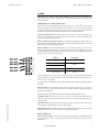
Martin University
MAC 2000 Service Seminar
TROUBLESHOOTING
GENERAL
FIXTURE DOES NOT RESET
Blown fuse: LEDs on the printed circuit board light up to indicate the power supplies are
working. Check / replace the fuses on the circuit board if one or more of the LEDs is not lit.
Sensor connection reversed: MAC 2000 will not reset properly if any of the Hall sensor
connections for the gobo wheels, gobo rotation, color wheel, effect wheel, or effect rotation
are reversed.
FIXTURE RESETS BUT DOES NOT RESPOND TO THE CONTROLLER
Incorrect XLR pin-out: The XLR pin-out is DMX standard, i.e., pin-2 (-) and pin-3 (+).
The fixture will not respond if the polarity is reversed, for example, if the MAC 2000 is
connected after a PAL 1200 without a phase-reversing cable.
Failure in the link: Diagnosing link problems is beyond the scope of this seminar. See
Recommended Practice for DMX512, A Guide for Users and Installers, by Adam
Bennette, available from PLASA, Ltd. and USITT Inc.
SOFTWARE UPLOAD
The MAC 2000 is compatible with the MP2 Uploader and the ISA DMX interface card for
the LightJockey Club controller. Version 4.0 of the Martin Software Uploader Utility is
required.
FIXTURE DOES NOT ACCEPT SOFTWARE (CSER)
Corrupted software: The MAC 2000 may not respond to the uploader if the fixture
software is corrupted. It can be forced into upload mode by moving the jumper on the
motherboard at PL 103 to the “INIT” position.
© 2000 Martin Professional A/S, Denmark
CPU write protected: The jumper at PL 102 prevents software upload when it is in the
“UPLOAD DISA.” position. Move it to “UPLOAD ENA.”, which is the factory default
position.
Troubleshooting
1
Martin University
MAC 2000 Service Seminar
MOTORS
To avoid damage to the step drivers, always turn off the power before connecting or
disconnecting the motors.
The pan and tilt motors in the MAC 2000 are 3-phase stepper motors. All other motors are
2-phase steppers.
Important!
NEVER test 3-phase drivers with the Martin step drive tester!
STEP MOTOR DOES NOT TURN, OR TURNS ERRATICALLY
Burned-out step driver: Most step motor problems are due to a burned-out driver. A
burned-out driver results in erratic or no movement. Test 2-phase drivers with the Martin
step drive tester or switch the motor to another circuit.
Two LEDs on the PCB, LD 401 and 402, indicate the status of the 3-phase drivers. When
lit, one or more of the drivers is defective. If both of the LEDs are unlit, the 3-phase
drivers are okay.
gate(-)
(+) source
To test the 3-phase drivers, remove the fixture from power and disconnect the pan and tilt
motors. Measure the resistance across the driver gate and source pins by placing the
negative probe on the G (gate) pin and the positive probe on the S (source) pin as shown. A
very low reading, below 10 ohms or so, indicates a defective driver.
If the drivers pass the resistance test but you still suspect them, you can also check the
drivers with an oscilloscope. Set the voltage scale to 10 V and the time scale to 10 µs: with
the motors connected, one will see a square wave signal across the output to the motor if
the driver is working properly.
Bad connection: Check continuity between the motor and the PCB. Alternatively, check
the connections from the PCB to the connection block by putting a working motor on the
circuit. Check the wires from the motor by plugging it into a working circuit.
Burned out motor: You should only feel slight resistance when turning a step motor by
hand. Replace the motor if it is hard to turn. You can also check for equal resistance on the
windings. The resistance should be close to the values shown below.
© 2000 Martin Professional A/S, Denmark
Motor
P/N
Where used
Approximate coil resistance
Stepmotor, standard mini, 22 mm shaft
05701201
cyan, yellow
120 ohms. Measure across pins 1&3, 4&6.
Stepmotor, standard mini, 10 mm shaft
05701202
magenta, CTC
120 ohms. Measure across pins 1&3, 4&6.
Stepmotor standard small (micro)
05701601
gobo 1 rotation, gobo 2 rotation
145 ohms. Measure across pins 1&3, 4&6.
Stepmotor, standard small, 22 mm shaft
05701602
gobo 1 shift
140 ohms. Measure across pins 1&3, 4&6.
Stepmotor, standard small, 12mm shaft
05701603
iris, gobo 2 shift, color shift,
140 ohms. Measure across pins 1&3, 4&6.
Stepmotor, standard medium, 9V micro
05701606
effect shift & rotation, focus, zoom 40 ohms. Measure across pins 1&3, 4&6.
Stepmotor, standard medium 12V HT
05701607
dimmer (2)
65 ohms. Measure across pins 1&3, 4&6.
Stepmotor, 3 phase
05703801
pan (2), tilt (2)
4 ohms. Measure across pins 1&3, 1&7, 3&7.
(Pin 1 = yellow, pin 3 = blue, pin 7 = yellow)
MOTOR TURNS THE WRONG DIRECTION
Reversed motor cable: Unplug the motor cable and flip it over.
Troubleshooting
2
Martin University
MAC 2000 Service Seminar
LAMP
The lamp circuit is similar to other Martin discharge lamp fixtures such as the MAC 500.
Note, though, that there are 2 thermo-switches in the lamp circuit and a door switch in the
lamp relay circuit.
LAMP DOES NOT STRIKE (LERR, HOT)
The main reasons for lamp failure are a blown lamp, a hot lamp, and incorrect power
settings. Discharge lamps become harder to strike with use - an incorrect power setting
may not be immediately apparent. Check the settings, allow the lamp to cool, and/or try
another lamp. If this does not help, the problem may be one of the following.
No power to the lamp: Turn the lamp on from the control panel. If you can hear the lamp
relay “click”, the door switch is closed and the control circuit is working. If the relay does
not close, check the door switch first.
Defective phase compensation capacitor: A bad phase compensation capacitor (the two
large capacitors next to the ballast) will result in increased input current and may cause the
main fuses to blow when striking the lamp.
Defective ballast: You can test the ballast with an inductance meter if you have one.
Disconnect the fixture from power, remove the brown wire, place the common probe on the
neutral terminal, and place the hot probe on an input terminal. A good ballast will provide
readings very close to those shown below.
Setting
Inductance
208 V / 60 Hz
28 mH
208 V / 60 Hz
230 V / 60 Hz
208 V / 50 Hz
208 V / 50 Hz
32 mH
230 V / 60Hz
230 V / 50 Hz
230 V / 50 Hz
39 mH
245 V / 50 Hz
42 mH
245 V / 50 Hz
Lower readings mean the ballast is providing too much current and the higher readings
mean the ballast is providing too little current. Note that the measurement will be too low if
the brown wire is connected.
If you don’t have an inductance meter, test the fixture with a known good ballast before
replacing .
Defective starter: The specified starter output is 5000 to 7000 V. Never attempt to
measure the starter output with normal meters! The high voltage is dangerous and will
damage your equipment.
Replace the starter if the lamp still does not strike after eliminating other causes.
© 2000 Martin Professional A/S, Denmark
Lamp does not fit: The MAC 2000 uses a new version of the HMI 1200 W/S that has
keyed slots on the ends instead of threads. Forcing the wrong lamp into the holder will
cause problems.
Open door switch: An open door switch opens the lamp relay and/or prevents it from
closing. Make sure the lamp access plate is fully seated.
Open thermal switch: The MAC 2000 has two thermal switches in series with the lamp.
A defective switch or poor connection can cause lamp strike failure.
SHORT LAMP LIFE
Incorrect power setting: Lamp life will be shortened considerably if the ballast setting is
incorrect and the voltage is too high. Refer to the user manual for proper setting
information.
Troubleshooting
3
Martin University
MAC 2000 Service Seminar
Contaminated lamp: Oils from your fingers or other sources will burn into the glass
envelope, weaking it and reducing performance.
Defective ballast: Defective ballast can provide too much power to the lamp and result in
shorter lamp life.
LAMP CUTS OUT/ FIXTURE OVERHEATING (HTER, BTER)
Incorrect power setting: See the user manual for proper setting information.
Dust and dirt reducing air-flow: Clean the fixture, and check the air flow filters in the
head.
Bad fan or connection: Both fans in the head must be operating to provide adequate
cooling. Check that the fans are connected and working.
Defective thermo-switch: The thermo-switches - there are two - cut power to the lamp if
the fixture overheats. A faulty thermo-switch may cause the lamp to cut out at too low a
temperature. Never bypass the thermo-switches!
COLOR WHEEL
COLOR WHEEL LOSES STEP
Defective motor or motor driver. Check motor, cables, and driver accordingly.
COLOR WHEEL ROTATES SPONTANEOUSLY
Improper adjustment: This can occur when the fixture reaches operating temperature if
there is too much distance between the wheel’s magnet and the sensor IC. When the wheels
are properly aligned and in the adjustment position, the sensor must be parallel with the
magnet and directly over it at a distance of no more than 1.5 mm (1/16 in).
COLOR WHEEL TIME OUT (COER)
Improper alignment: The sensor may not be able to detect the indexing magnet if the
wheel is out of alignment. Refer to the color wheel adjustment procedure. If the color
wheel fails to reset when it is properly aligned, the sensor IC may be too far from the
indexing magnet. The maximum distance between the sensor and the magnet is 1.5 mm.
GOBOS AND EFFECTS
WHEELS LOSE STEP
Defective motor or motor driver. Check motor, cables, and driver.
© 2000 Martin Professional A/S, Denmark
WHEEL ROTATES SPONTANEOUSLY
Improper adjustment: This can occur when the fixture reaches operating temperature if
there is too much distance between the wheel’s magnet and the sensor IC. When the wheel
is properly aligned and in the adjustment position, the sensor must be parallel to the
magnet and directly over it at a distance of no more than 1.5 mm.
TIME OUT (G1ER, G2ER, R1ER, R2ER, EFER, REER)
Improper alignment: The sensor may not be able to detect the indexing magnet if the
wheel is out of alignment. If the wheel fails to reset when properly aligned, or if the
rotating-gobo or effect indexing fails, the sensor IC may be too far from the indexing
magnet. The maximum distance between the sensor and the magnet is 1.5 mm.
Troubleshooting
4
Martin University
MAC 2000 Service Seminar
ROUGH OR NOISY GOBO OR EFFECT SELECTION
Belt too tight: Adjust tension.
Loose wheel: A noisy wheel probably indicates that the screws connecting the wheel to
the shaft adaptor are loose. Apply Loc-tite and tighten.
ROUGH GOBO OR EFFECT ROTATION
Worn, dirty, or dry bearing: Clean and lubricate the bearing with silicone lubricant.
Replace the bearing if necessary.
GOBOS SLIP IN HOLDER OR FALL OUT
Gobo retaining spring not seated correctly: The narrow end of the gobo retention
spring must be inserted against the gobo. Squeeze the spring flat to see which end is
narrowest. Make sure the wide end of the spring is fully seated under the lip of the holder.
Effect glass must be glued into the holders.
GOBOS DO NOT INDEX CORRECTLY
Worn, dirty, or dry bearing: Clean and lubricate the bearing with silicone lubricant.
Replace the bearing if necessary.
COLOR MIXING
COLOR FLAGS LOSE STEP
Defective motor or motor driver. Check motor, cables, and driver.
CMY MODULE TIMEOUT (CYER, MAER, YEER, CTER)
Improper adjustment of the indexing switch: Adjust the indexing switch so that it is
activated approximately 1 mm before the filter reaches the mechanical stop.
Improper belt mounting: Check that the plastic male clip is fully mated with the plastic
female part of the drive sled.
Loose drive pulley: Tighten drive pulley.
ROUGH MOVEMENT
Improper belt tension: If the drive belt is too tight or too loose, color mixing will be
choppy or difficult.
Slides need lubrication: Apply an extremely light film of recommended Martin High
temperature Silicone oil to the slides. Apply 1 small drop and spread evenly. It is better to
have too little oil than too much.
© 2000 Martin Professional A/S, Denmark
IRIS
IRIS LOSES STEP OR MOVES ERRATICALLY
Defective motor or motor driver. Check motor, cables, and driver.
NOISY IRIS
Iris noise at fast speed, can be caused from vibrations from the drive motor. Operating the
iris at slower speeds reduces the noise. Replacing the iris is the only other solution.
Troubleshooting
5
Martin University
MAC 2000 Service Seminar
VISIBLE IRIS GRAPHITE
Excess graphite powder can accumulate at the edge of the iris blades and become visible in
the projected image. This excess may be removed by blowing it away. Be careful though
not to get the powder on lenses and other optical parts.
FOCUS, AND ZOOM
FOCUS OR ZOOM LENS LOSES STEP OR MOVES ERRATICALLY
Defective motor or motor driver. Check motor, cables, and driver.
FOCUS OR ZOOM TIMEOUT (FOER, ZOER)
The focus or zoom is not activating the indexing switch. Refer to adjustment procedure.
ROUGH FOCUS OR ZOOM
Improper belt tension: If the drive belt is too tight or too loose, focus/zoom action will
be choppy or difficult.
© 2000 Martin Professional A/S, Denmark
Slides need lubrication: Apply an extremely light film of recommended Martin High
temperature Silicone oil to the slides. Apply 1 small drop and spread evenly. It is better to
have too little oil than too much.
Troubleshooting
6
Martin University
MAC 2000 Service Seminar
SHUTTER/ DIMMER
RANDOM SHUTTER ACTION
Bad connection: If there is a bad connection to the drive motors. Check that all wires are
securely crimped in the connector. To avoid damaging the step drivers, always turn off the
power before connecting or disconnecting motors.
Loose adaptor: Check and tighten the adaptors on the dimmer blades.
Bad motor: The dimmer may continue to work even if one of the motors is defective.
PAN/ TILT
PAN OR TILT FAILS TO RESET (FBER)
Defective indexing switch: A defective micro-switch will not reset the feed back circuit,
and the motors will try to move the head longer than the mechanical stop, until a time-out
stops the motors. Close the switch manually and check for continuity across the contacts.
Improper pan reset switch adjustment: Adjust switch.
FEEDBACK ERROR (FBEP, FBET)
Dirty optical sensor: The pan and tilt position sensors are optical, and must not be
obstructed by dust or dirt. Clean the sensor with compressed air.
Bad connection: Check the cables from the sensors to the main PCB.
Defective optical sensor: There are 2 pan sensors and 2 tilt sensors. These can be tested
with an oscilliscope while the fixture is operating. Good sensors display a square 5 V wave
that varies in frequency with pan or tilt speed. Test the pan sensors across pins 2 & 3 and
pins 2 & 4 of PL301 on the main PCB. Test the tilt sensors across pins 2 & 3 and pins 2 &
4 of PL302.
Loose timing wheel:
HEAD STICKS IN YOKE
The head may get stuck if the arm covers are not seated correctly.
PAN AND TILT NOISY, SLOW, OR LOSING STEP
Motors out of (mechanical) phase: Adjust pan or tilt motors.
Different personality setting: Check that all fixtures have the same pan/tilt speed and
studio mode settings. Refer to the user manual.
© 2000 Martin Professional A/S, Denmark
Bad connection: If there is a bad connection to one of the drive motors, the other motor
will lose step, resulting in slower movement. Check that all wires are securely crimped in
the connector. To avoid damaging the step drivers, always turn off the power before
connecting or disconnecting motors.
Loose drive gear: To check and tighten the drive gears, refer to the procedures for pan and
tilt belt replacement.
Bad motor: Pan and tilt may continue to work even if one of the motors is defective. See
above.
Troubleshooting
7