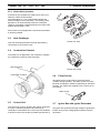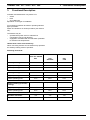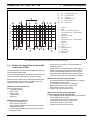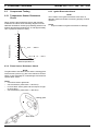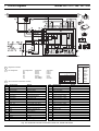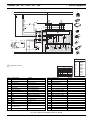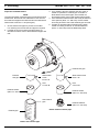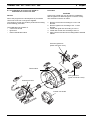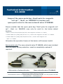
1
Water Heaters
Workshop Manual
Thermo 230
Thermo 300
Thermo 350
with control unit 1572
model .30 and up
Thermo 230
Thermo 300
Thermo 350
with control unit 1572D
model .030 and up
Thermo 231
Thermo 301
model .01 and up
Thermo Rail
12/2012
Ident Nr. 9003656C II
Thermo 230 / 231 / 300 / 301 / 350
List of Contents
List of Contents
1.
Introduction
1.1
1.2
1.3
1.4
1.5
Scope and Purpose ............................................................................................................................... 101
Applicability of Manual ........................................................................................................................... 101
Meaning of Warnings, Cautions and Notes ........................................................................................... 101
Additional Documentation to be used .................................................................................................... 101
Safety Information and Regulations....................................................................................................... 101
1.5.1 General Safety Notes ................................................................................................................. 101
1.6
1.7
2.
Legal Provisions for Installation ............................................................................................................. 102
Corrections and Improvements.............................................................................................................. 103
General Description
2.1
2.2
Combustion Air Fan ............................................................................................................................... 202
Fuel Pump ............................................................................................................................................. 202
2.2.1 Nozzle block preheater............................................................................................................... 203
2.3
2.4
2.5
2.6
2.7
2.8
2.9
2.10
2.11
Heat Exchanger ..................................................................................................................................... 203
Combustion Chamber............................................................................................................................ 203
Control Unit............................................................................................................................................ 203
Flame Sensor ........................................................................................................................................ 203
Igniter Box with Igniter Electrodes ......................................................................................................... 203
Temperature Sensor.............................................................................................................................. 204
Temperature Limiter .............................................................................................................................. 204
Overheat Thermostat (Thermo 231 and 301 only) ................................................................................ 204
Circulation Pump ................................................................................................................................... 204
2.11.1 Aquavent 5000 (U4814) and Aquavent 5000S (U4854) circulating pumps................................ 205
2.11.2 Aquavent 6000C (U4855) and Aquavent 6000SC (U4856) circulating pumps............................205
2.12 Fuel Filter............................................................................................................................................... 206
3.
Functional Description
3.1
3.2
3.3
3.4
3.5
3.6
3.7
3.8
3.9
4.
Switch On .............................................................................................................................................. 302
Heating Operation.................................................................................................................................. 302
Switch Off .............................................................................................................................................. 303
Power Save ........................................................................................................................................... 303
Auxiliary Heating Operation (heaters with control unit 1572D only) ...................................................... 303
Heater Lockout (heaters with control unit 1572D only).......................................................................... 303
Switch-off upon Failure (heaters with control unit 1572)........................................................................ 303
Switch-off upon Failure (heaters with control unit 1572D) ..................................................................... 305
Error Code Output (heaters with control unit 1572D) ............................................................................ 306
Technical Data
Electrical components...................................................................................................................................... 401
Propellant......................................................................................................................................................... 401
I
List of Contents
5.
Thermo 230 / 231 / 300 / 301 / 350
Troubleshooting
5.1
5.2
5.3
General ................................................................................................................................................. 501
General Fault Symptoms ...................................................................................................................... 501
Fault Symptoms during Functional Checkouts and Error Code Output or Tests with
Diagnostic Computer, Components Tester or PC Heater Diagnosis .................................................... 503
5.3.1 General ...................................................................................................................................... 503
5.3.2 Fault Symptoms......................................................................................................................... 504
6.
Functional Checkouts
6.1
6.2
General ................................................................................................................................................. 601
Adjustments .......................................................................................................................................... 601
6.2.1 Adjustment of CO2 Contents ..................................................................................................... 601
6.3
Components Testing............................................................................................................................. 602
6.3.1
6.3.2
6.3.3
6.3.4
6.3.5
6.3.6
6.3.7
6.3.8
7.
602
602
602
603
603
604
604
604
Circuit Diagrams
7.1
8.
Temperature Sensor Resistance Check....................................................................................
Flame Sensor Resistance Check ..............................................................................................
Igniter Electrodes Check ...........................................................................................................
Igniter Box Check ......................................................................................................................
Fuel Pump Check ......................................................................................................................
Fan Motor Check .......................................................................................................................
Solenoid Valve Check ...............................................................................................................
Nozzle Block Preheater Check ..................................................................................................
General ................................................................................................................................................. 701
Servicing
8.1
8.2
8.3
8.4
8.5
General .................................................................................................................................................
Heater Servicing ...................................................................................................................................
Vehicle Servicing ..................................................................................................................................
Heater Test Run....................................................................................................................................
Maintenance .........................................................................................................................................
801
801
801
801
801
8.5.1 Inspection and Attachment of the Exhaust Muffler (only heaters from year of
production 1996 and up to production date 1996, calendar week 36; 3G......) .......................... 801
8.5.2 Burner Head Opening and Closing or Removal and Installation ............................................... 803
8.6
Visual Inspections and Regulations for Installation............................................................................... 804
8.6.1
8.6.2
8.6.3
8.6.4
8.7
804
804
806
806
Removal and Installation....................................................................................................................... 807
8.7.1
8.7.2
8.7.3
8.7.4
II
Connection to Vehicle Cooling System .....................................................................................
Connection to Vehicle Fuel System...........................................................................................
Combustion Air Supply ..............................................................................................................
Exhaust Line ..............................................................................................................................
Heater, Removal and Installation ..............................................................................................
Temperature Limiter, Replacement ...........................................................................................
Temperature Sensor, Replacement ..........................................................................................
Burner, Replacement.................................................................................................................
807
807
807
807
Thermo 230 / 231 / 300 / 301 / 350
List of Contents
8 7.5 Igniter Box, Replacement ........................................................................................................... 807
8.7.6 Flame Sensor, Replacement ...................................................................................................... 808
8.7.7 Combustion Chamber, Replacement ......................................................................................... 808
8.8
First Operation ....................................................................................................................................... 808
8.8.1 Water Circuit, Bleeding............................................................................................................... 808
8.8.2 Fuel Supply System, Bleeding.................................................................................................... 808
9.
Repair
9.1
General .................................................................................................................................................. 901
9.1.1 Work on Components after Disassembly ................................................................................... 902
9.1.2 Incorporation of Modifications..................................................................................................... 902
9.2
Disassembly and Assembly................................................................................................................... 906
9.2.1
9.2.2
9.2.3
9.2.4
9.2.5
9.2.6
9.2.7
9.2.8
9.2.9
9.2.10
9.2.11
10.
Temperature Limiter, Replacement ............................................................................................ 904
Temperature Sensor, Replacement ........................................................................................... 904
Burner, Replacement.................................................................................................................. 904
Combustion Air Fan, Replacement............................................................................................. 906
Control Unit, Replacement ......................................................................................................... 908
Fuel Pump, Replacement ........................................................................................................... 908
High Pressure Nozzle, Replacement...........................................................................................908
Igniter Box, Replacement ........................................................................................................... 910
Flame Sensor, Replacement ...................................................................................................... 910
Heat Exchanger, Replacement................................................................................................... 912
Combustion Chamber, Replacement ......................................................................................... 912
Packaging, Storage and Shipping
10.1 General ................................................................................................................................................ 1001
Annex A
Heater, Scheduled Maintenance...................................................................................................................... A-2
III
List of Contents
Thermo 230 / 231 / 300 / 301 / 350
List of Figures
301
302
Functional Sequence (heaters with control unit 1572) .................................................................................... 304
Functional Sequence (heaters with control unit 1572D) ................................................................................. 305
501
General Fault Symptoms ................................................................................................................................ 501
701
702
703
704
705
706
707
708
709
710
Automatic Control Circuit with Control Unit 1572 and Switch ......................................................................... 702
Automatic Control Circuit with Control Unit 1572 and Timer (Triple Timer) .................................................... 703
Automatic Control Circuit with Control Unit 1572D and Switch....................................................................... 704
Automatic Control Circuit with Control Unit 1572D and Standard Timer......................................................... 705
System Circuit Daimler Chrysler Citaro, Ident.-Nr. 67131................................................................................ 706
System Circuit Van Hool, Ident.-Nr. 89401 ...................................................................................................... 707
System Circuit O405 / O407 / O408, Ident.-Nr. 91292..................................................................................... 708
System Circuit MAN, Ident.-Nr. 89404 ............................................................................................................. 709
System Circuit SETRA, Ident.-Nr. 90972 ......................................................................................................... 710
Automatic Control Circuit Rail with Control Unit 1572D and Standard Timer and filter heater ........................ 711
801
802
Swinging Burner Head open ........................................................................................................................... 803
Example of a Heater Installation in a Passenger Bus ..................................................................................... 805
901
902
903
904
905
Temperature Limiter, Temperature Sensor and Burner, Replacement...........................................................
Combustion Air Fan, Replacement .................................................................................................................
Control Unit and Fuel Pump, Replacement.....................................................................................................
Igniter Box and Flame Sensor, Replacement ................................................................................................
Heat Exchanger and Combustion Chamber, Replacement ............................................................................
IV
905
907
909
910
912
Thermo 230 / 231 / 300 / 301 / 350
1.
Introduction
1.1
Scope and Purpose
This repair shop manual is intended to support
familiarized personnel in the repair of water heaters
Thermo 230, 231, 300, 301 and 350.
The water heater may only be operated with the specified
fuel (Diesel or also fuel oil EL) and the relevant designated
type of electrical connection.
1.2
Applicability of Manual
This manual is applicable only for heaters identified on the
title page. The different appearance of control units (see
2.5) allow to distinguish between model .30 and up with
control unit 1572 and the model .030 and up with control
unit 1572D.
In combination with control unit 1572D additionally a
different type of igniter box is installed (refer to 2.7).
The heaters Thermo 231 and 301 are variants for vertical
installation.
1.3
Meaning of Warnings, Cautions and
Notes
WARNINGS, CAUTIONS, and NOTES in this manual
have the following meaning:
WARNING
This heading is used to highlight that non-compliance with
instructions or procedures may cause injuries or lethal
accidents to personnel.
CAUTION
This heading is used to highlight that non-compliance
with instructions or procedures may cause damage to
equipment.
NOTE
This heading is used to highlight and draw specific
attention to information.
1 Introduction
1.4
Additional Documentation to be used
This workshop manual contains all information and
procedures necessary for the repair of heaters Thermo
230, 231, 300, 301 and 350 as well as Thermo Rail.
Operating instructions and installation instructions may be
used as complementary information as necessary.
1.5
Safety Information and Regulations
The general safety regulations for the prevention of
accidents and the relevant operating safety instructions
have to be observed at all times.
"General Safety Regulations" beyond the scope of these
regulations are detailed in the following.
The specific safety regulations applicable to this manual
are highlighted in the individual chapters by Warnings,
Cautions, and Notes.
1.5.1 General Safety Notes
The year of first operation must be permanently
marked on the identification label by removing the
relevant number of the year.
The heaters are cleared for heating the vehicle engine
and the passenger cabin. The use of the heater in
vehicles not subject to the EU Directive 70/156/EEC (e.g.
ships) is partly governed by regional regulations.
For heaters designed for installation in rail vehicles, type
approval has been granted (not for Thermo 231 and 301)
by the Federal Railway Authority with the type approval
number: EBA 32AZ3/0174/08.
The heater may only be fitted in vehicles or in independent
heating systems with a minimum coolant capacity of
10 liters.
The heater may only be installed in motor vehicles or in
independent heating systems with a minimum coolant
capacity of 6 liters.
The heater must not be installed in the passenger or driver
compartments of vehicles. Should the heater nevertheless be installed in such a compartment, the installation
box must be sealed tight against the vehicle interior.
There must be sufficient ventilation of the installation box
from the exterior in order not to exceed a maximum
temperature of 85 °C in the installation box. Excessive
temperatures may cause malfunctions.
WARNING
Due to the danger of poisoning and suffocation the
heater must not be operated, not even with timed
operation, in enclosed areas such as garages or
workshops not equipped with an exhaust venting
facility.
101
1 Introduction
At filling stations and fuel depots the heater must be
switched off to prevent explosions.
CAUTION
Where flammable fumes or dust may build up (e.g. in
the vicinity of fuel, coal, wood, cereal depots, or
similar installations) the heater must be switched off
to prevent explosions.
The heater must not be operated near flammable materials such as dry grass and leaves, cardboard
boxes, paper, etc.
In the vicinity of the water heater a temperature of 110 °C
(storage temperature) must not be exceeded under any
circumstances (e.g. during body paint work).
A violation of this temperature limit may cause permanent
damage to the electronics.
When checking the cooling water level proceed in
accordance with the vehicle manufacturer’s instructions.
The water in the heating circuit of the heater must contain
a minimum of 10% of a quality brand anti-freeze.
Thermo 230 / 231 / 300 / 301 / 350
(Extract from Directive 2001/56/EC Annex VII)
1.7.1. A clearly visible indicator within the user's field of
vision must show when the heater is switched on or off.
NOTE:
For further notes and provisions relating to the installation
of the heater in vehicles, refer to the installation instructions.
IMPORTANT
Failure to follow the installation instructions and the notes
contained therein will lead to all liability being refused by
Spheros. The same applies if repairs are carried out incorrectly or with the use of parts other than genuine spare
parts. This will result in the invalidation of the type approval for the heater and therefore of its homologation / EC
type licence.
Installation Instructions for Spheros fuel tanks for the fuel
supply of water heaters in vehicles:
•
Additives in the heating circuit must not affect metals,
plastics and rubber and must leave no deposits.
The opening pressure in the vehicle cooling system normally indicated on the radiator filler cap - must be
between 0.4 and 2.0 bar above operating pressure (also
applicable to separate heating circuits).
1.6
Legal Provisions for Installation
With effect from 4/03, Type Approvals pursuant to EC Directives 72/245/EEC (EMC) and 2001/56EC (Heating Systems) were granted for the heaters Thermo 230 / Thermo
231 / Thermo 300 / Thermo 301 / Thermo 350 with the following EC Type Approval Numbers:
e1*72/245*95/54*1010*-e1*2001/56*0007*-- for Thermo 230
e1*2001/56*0008*-- for Thermo 300
e1*2001/56*0009*-- for Thermo 350
e1*2001/56*0010*-- for Thermo 231
e1*2001/56*0011*-- for Thermo 301
Up to 4/03, General Design Certifications existed for these
heaters.I
nstallation is governed above all by the provisions in
Annex VII of Directive 2001/56/EC.
NOTE:
The provisions of these Directives are binding within
the territory governed by EU Directive 70/156/EEC
and should similarly be observed in countries without
specific regulations.
102
•
•
in busses and trains the installation is not permitted in
the passengers’ or driver’s compartment.
the fuel filler neck must not be located in the passengers’ or driver’s compartment of any vehicle.
fuel containers must either be equipped with a vent
cap or any other type of ventilation (vent line).
Only vent caps in accordance with DIN 73400 may be
used.All fuel containers offered in the Spheros Accessories Catalogue are suitable for a maximum operating pressure of 0.15 bar overpressure.
All fuel containers offered in the Spheros Accessories Catalogue are subjected during manufacture to individual
pressure testing with at least 0.3 bar overpressure.
•
The operational state of the heater, i.e. at least an
indication "on" or "off" must be easily and clearly visible.
For heaters in vehicles not ruled by the EU Directive but
other regulations, the acceptance by the relevant authority is required as applicable.
Thermo 230 / 231 / 300 / 301 / 350
1.7
1 Introduction
Corrections and Improvements
Deficiencies, improvements, or proposals for correction of
this workshop manual are to be mailed to:
Spheros GmbH
Friedrichshafener Straße 9 - 11
D-82205 Gilching
Telefon: +49 (0)8105 7721 887
Telefax: +49 (0)8105 7721 889
www.spheros.de / [email protected]
103
1 Introduction
Page empty for notes
104
Thermo 230 / 231 / 300 / 301 / 350
Thermo 230 / 231 / 300 / 301 / 350
2
The heaters Thermo 230, 231, 300, 301 and 350 basically
consist of
General Description
The water heaters Spheros Thermo 230, 231, 300, 301
and 350 are used in combination with the vehicle’s own
heating installation to
–
–
–
2 General Description
heat the passenger compartment
defrost the windscreen
preheat water-cooled engines
–
–
–
–
–
the combustion air fan
the fuel pump with nozzle block and nozzle
the heat exchanger and
the combustion chamber
the igniter box with igniter electrodes
For control and monitoring the heater includes
The heaters Thermo 231 and 301 are variants for vertical
installation. The difference in appearance are the different
identification label and the Z profiles on the installation interface.
The water heater operates independent from the vehicle
engine and is connected to the vehicle cooling system,
the fuel system and the electrical system.
The heater designed to the heat exchanging principle
operates intermittently controlled by the temperature
sensor.
–
–
–
–
–
a control unit
a flame sensor
a temperature sensor
a temperature limiter
a temperature limiter without reset button for Thermo
231 and 301 and the Rail variant .126.
An external circulating pump is installed inside the vehicle,
or, in the case of compact units, directly at the heater.
4
3
2
5
1
Thermo 231/301
6
11
7
8
10
9
Thermo 231/301
1
2
3
4
5
6
7
8
9
10
11
Burner
Coolant inlet
Temperature limiter
Temperature sensor
Coolant outlet
Heat exchanger
Exhaust outlet
Fuel return
Combustion air inlet
Fuel delivery
Splash protection cover
(instead of screen)
201
2 General Description
2.1
Thermo 230 / 231 / 300 / 301 / 350
Combustion Air Fan
Solenoid valve
The combustion air fan supplies the air required for
combustion from the combustion air inlet to the combustion chamber.
Nozzle block
pre-heater (optional)
Fan motor
Splash protection cover
Screen
Fan wheel
Screen
Cap
O-ring
Fuel Pump
The fan consists of a fan motor with fan wheel. Air is taken
in through a splash protection cover or a screen and the
cap. The heaters Thermo 231 and 301 are provided with
a splash protection cover only.
2.2
Fuel Pump
The fuel pump is responsible for fuel supply.
The pump is driven by the burner motor via a coupling.
Fuel is compressed in the fuel pump to approx. 10 bar and
atomised via the atomiser nozzle.
The solenoid valve integrated into the fuel pump opens
and closes the fuel supply to the atomiser nozzle.
Three different fuel pumps are assigned to the different
heating capacity classes of the Thermo series.
These are identified by the heating capacity class specification as well as colour dots:
•
•
•
16 KW:
23-35 KW:
40 KW:
1 color dot
2 color dots
3 color dots
Color dots for
identification
of the heating
capacity class
The fuel pump can be used in dual-line operation (fuel
supply and return line).
If the heater is operated with
–
–
–
–
a long fuel supply line
check valves in the fuel supply and return line
a fuel filter in the fuel supply line
single-line operation
the fuel supply line must be filled prior to first heater
start-up.
202
Thermo 230 / 231 / 300 / 301 / 350
2 General Description
2.2.1 Nozzle block preheater
At extremely low temperatures malfunctions may occur
without a nozzle block preheater.
At a temperature of < 0°C a thermostat activates the
heater cartridge in the nozzle block. The heating period
depends on the heat reflected within the combustion
chamber. Preheating is deactivated when the thermostat
ambient temperature is +8°C.
If the heater is not equipped with a nozzle block preheater
a retrofit is possible.
2.3
Heat Exchanger
Control Unit 1572
IThe heat exchanger transfers the heat generated by
com-bustion to the coolant circuit.
2.4
Combustion Chamber
The fuel/air mix is dispersed in the combustion chamber
for combustion to heat the heat exchanger.
Heat exchanger
Control Unit 1572D
Combustion chamber
2.6
Flame Sensor
The flame sensor continuously monitors the flame
condition during operation. The flame sensor is a photo
transistor changing its resistance depending on the flame
intensity. The signals are supplied to the control unit for
processing.
Flame sensor
2.5
Control Unit
The control unit 1572 or 1572D is the central component
to ensure controlled operation and monitoring of
combustion. If the heater has a control unit 1572 installed,
a retrofit of control unit 1572D is possible (see Section 9).
2.7
Igniter Box with Igniter Electrodes
The igniter box generates the high voltage for igniting the
fuel/air mix by a high voltage ignition spark across the
electrodes.
203
2 General Description
Thermo 230 / 231 / 300 / 301 / 350
Igniter electrodes
Igniter box
(black connector
cover) only in
combination with
control unit
1572
2.8
Igniter box (green connector
cover; mechanically coded)
in combination with
control unit
1572D
and also
control
unit 1572
2.10 Overheat Thermostat for burner
(Thermo 231 and 301 only)
The overheat thermostat is screwed onto the disk and
electrically connected to the solenoid valve of the fuel
pump. When the burner overheats the thermostat causes
an error lockout.
Temperature Sensor
The temperature sensor senses the coolant temperature
at the heat exchanger outlet as an electrical resistance.
This signal is supplied to the control unit for processing.
2.9
Temperature Limiter
Overheat Thermostat
2.11 Circulation Pump
The temperature limiter (bimetal) protects the heater
against undue high operating temperatures.
The temperature limiter can be reset manually.
The temperature limiter responds at a temperature in
excess of 125°C to switch off the heater.
In the case of Thermo 231 and 301 as well as the Rail
variant .126, the temperature limiter will trip at a
temperature in excess of 105°C.
After the temperature has dropped, an automatic reset will
occur.
The externally mounted circulation pump ensures proper
coolant circulation in the vehicle and heater circuit.
Depending on the application, the circulating pump is
switched on via the control unit or directly via the vehicle
electrical system and operated during the entire heater
operation duration.
The heaters can be operated with the circulation pumps
Aquavent 5000 (U4814), Aquavent 5000S (U4854),
Aquavent 6000C (U4855) or Aquavent 6000SC (U4856).
Rated voltage
Operating voltage range
Rated power consumption
Weight
l/h
V=
V=
W
kg
U 4814
Aquavent
5000
5000
(against 0,2 bar)
12
or
24
10…14
or
20…28
104
2,1
U 4854
Aquavent
5000S
5000
(against 0,2 bar)
24
20…28
104
2,2
U 4855
Aquavent
6000C
6000
(against 0,4 bar)
24
20…28
210
2,4
U 4856
Aquavent
6000SC
6000
(against 0,4 bar)
24
20…28
210
2,5
Circulating pump
Delivery rate
Temperature sensor
Temperature
limiter
The circulating pump fuse may never be pulled, while the
pump is running, and may not be replaced, when the
pump is switched on.
204
Thermo 230 / 231 / 300 / 301 / 350
2 General Description
2.11.2 Aquavent 6000C (U4855) and Aquavent
6000SC (U4856) circulating pumps
Aquavent 5000
(U4814)
The Aquavent 6000C (U4855) andAquavent 6000SC
(U4856) circulating pumps are equipped with a brushless
motor.
NOTE
The Aquavent 6000C (U4855) has a floating-ring type
shaft seal.
The Aquavent 6000SC (U4856) is equipped wit a
magnetic coupling (no seal).
Aquavent 5000S
(U4854)
Aquavent 6000C
(U4855)
Aquavent 6000SC
(U4856)
Soft start
The circulating pump motor starts slowly and gently. Max.
rotational speed is only reached after approx. 5 seconds.
Protection against dry running
Protection against dry running is integrated into the
circulating pump motor.
If the circulating pump motor consumes within a time
period of approx. 45 minutes significantly less current, dry
running is detected. The circulating pump motor is
switched off.
After approx. 2 minutes and circulating pump motor
reactivation, the operation can be continued.
Blocking protection
If the pump wheel is blocked, the motor will be switched
off via the error mode directly prior to standstill of the
pump wheel.
Overload protection
Overload protection is activated after the soft start is
completed. The current consumption will be limited.
In case of hydraulic overpressuring of the circulating
pump, the circulating pump motor will not be damaged.
Fehlermodus
In case of malfunctions the circulating pump motor is
switched off via the error mode. After approx. 5 seconds
the error mode switches the circulating pump motor into
energy-saving sleep mode.
2.11.1 Aquavent 5000 (U4814) and Aquavent
5000S (U4854) circulating pumps
The Aquavent 5000 (U4814) and 5000S (U4854) circulating pumps are equipped with a brush motor.
NOTE
Aquavent 5000 (U4814) with floating-ring type shaft seal.
Aquavent 5000S (U4854) uncoupled by a magnet (no
seal)
ATTENTION
The circulating pump motor is not equipped with an
internal inverse-polarity protection.
Sleep mode
In sleep mode internal electronics consumers of the circulating pump motor are switched off.
Reactivation of the circulating pump motor
It is possible to reactivate the circulating pump motor from
sleep mode. For this purpose the power supply is
disconnected for > 2 min. After the power supply is
reconnected, the circulating pump motor restarts in softstart mode.
Inverse-polarity protection
The circulating pump motor is not equipped with an
internal inverse-polarity protection.
205
2 General Description
2.12 Fuel Filter
At compact devices of the series 230/300/350.126 and
.190 Rail an optional heatable fuel filter is provided, as an
additional option also for .124 and .155 Rail.
If the electrical filter heating is hooked-up, the temperature
switch turns the integrated filter heating
on
at ≤ 0,5 ± 2,5 °C and
off
at ≥ 5,5 ± 2,5 °C fuel temperature.
206
Thermo 230 / 231 / 300 / 301 / 350
Thermo 230 / 231 / 300 / 301 / 350
3.
3 Functional Description
Functional Description
Activation and deactivation is by means of a
• switch
• timer
• air conditioning
dependent on the type of installation.
For monitoring operation at least an operating indicator
light is provided.
Switch off releases a run-down procedure (see "Switch
off").
The heaters may be
• operated with power save for reduced fuel
consumption (see circuit diagram)
• equipped or retrofitted with a nozzle block preheater
for extreme low temperatures.
Heaters with control unit 1572D only
When connecting terminal +61 the heaters may operate in
the auxiliary heating mode of operation.
Switching thresholds
Control device
Ident. No. 63482E
Ident. No. 97806B
Bus
Ident. No. 97810B
Ident. No. 63859D
Rail
Standard
Rail
J.E.S
Upper operating point
85°C
85°C
85°C
Lower operating point
78°C
70°C
75°C
Upper operating point
85°C
80°C
85°C
Lower operating point
70°C
45°C
70°C
Upper operating point
70°C
20°C
70°C
Lower operating point
55°C
75°C
55°C
Gradient evaluation
Yes
Yes
Yes
Hysteresis adaption
Yes
Yes
Yes
Auxiliary heating
Parking heating
Parking heating (economic
setting)
301
3 Functional Description
Thermo 230 / 231 / 300 / 301 / 350
Switching thresholds for Thermo xxx Raill
230.040
Version Thermo xxx*
230.056
300.124
xxx.126
300.155
350.056
350.190
350.155
„VOSSLOH „VOSSLOH
“
“
Scope of delivery
973 13A
90 162 37x
thru
90 162 36A
973 13D
90 162 35A
90 210 12B
Heater
638 59D
679 81C
987 10x
978 04x
Upper operating point
85°C
85°C
85°C
85°C
Lower operating point
75°C
72°C
70°C
70°C
Control device
Auxiliary heating
Preheating
Parking heating
Upper operating point
85°C
75°C
60°C
60°C
Lower operating point
70°C
60°C
45°C
45°C
keeping frost-free
Parking heating (economic
setting)
Upper operating point
70°C
57°C
20°C
40°C
Lower operating point
55°C
42°C
5°C
25°C
Gradient evaluation
Yes
Yes
Yes
Hysteresis adaption
Yes
Yes
Yes
18,5V
Low voltage threshold
(20 sec.)
* xxx means 230 or 300 or 350
3.1
Switch On
3.2
Heating Operation
Upon switch on the operating indicator light goes on.
Combustion air fan, fuel pump and circulation pump start
operation. (If fitted and temperature is < 0 °C nozzle block
preheater is also activated).
After reaching operating temperature the control unit
takes over to provide controlled operation by activation
and deactivation of the burner in order to maintain a nearly
constant temperature of the heat exchanger (coolant).
After approximately 12 seconds (run-up time) the high
voltage igniter spark is available. Approximately 1 second
later the solenoid valve in the fuel pump opens and the
nozzle sprays fuel into the combustion chamber to be
ignited by the igniter spark. A photo control circuit
deactivates the igniter box after flame-up.
The heating operation is terminated as soon as the upper
operating point is exceeded.
The heater now is in the control idle period. Heater
operation is resumed when the temperature drops below
the lower operating point.
302
Thermo 230 / 231 / 300 / 301 / 350
Heaters with control unit 1572D only
Gradient evaluation
In case of low coolant flow or poor coolant circuit venting
the temperature quickly increases in heating operation.
If gradient evaluation exists, the control unit recognises
the quick temperature increase and automatically sets the
upper switching threshold to a lower value. This prevents
residual heat triggering the overheating protection.
Control idle period
A rise in temperature above the upper switching point
makes the solenoid valve in the fuel pump shut off the fuel
supply initiating the run-down. The flame extinguishes,
the combustion air fan and the circulation pump however
continue their operation. After approximately 90 seconds
(120 seconds for heaters with control unit 1572D)
run-down is completed with deactivation of the
combustion air fan.
3 Functional Description
burner after control idle period is raised above that for
normal operation and is automatically shifted up or down
dependent on the combustion time of the heater
(hysteresis adaptation).
Hysteresis adaptation (example)
After the first control idle period, the lower operating point
is 78°C.
Combustion operation is started when the temperature
falls below this threshold.
The length of combustion time until the upper operating
point is exceeded should be 120 seconds.
If combustion lasts more than 120 seconds, the lower
operating point is increased by 1 Kelvin, up to max. 80°C.
If combustion time is less than 120 seconds, the lower
operating point is lowered by 1 Kelvin, down to minimally
70°C.
The circulation pump remains in operation during the
control idle period. The operating indicator light is on.
3.6
3.3
Switch Off
Switching off the heater stops combustion. The operating
indicator light goes out and run-down commences. The
combustion air fan and circulation pump are deactivated
after approximately 90 to 120 seconds (120 seconds for
heaters with control unit 1572D).
Reactivation of the heater during run-down is permitted.
The burner immediately resumes operation after the
run-up time.
3.4
Power Save
With power save on the control temperatures of the
heating circuit are kept low. Combustion performance is
not reduced.
This results in a reduced heat radiation loss when limited
heating performance is required (e.g. in heat hold operation) cutting down fuel consumption.
3.5
Auxiliary Heating Operation (heaters
with control unit 1572D only)
When terminal +61 is connected and powered (engine is
running), the heater operates in the auxiliary heating
mode.
The power save mode is during auxiliary heating automatically deactivated by the control device.
The lower temperature threshold for reactivation of the
Heater Lockout (heaters with control
unit 1572D only)
After the heater has performed eight start attempts due to
a malfunction or after five subsequent flame-outs the
heater enters a lockout and start attempts are suspended.
This lockout is superior to the normal error lockout.
Unlocking is performed by starting the heater and
disconnection of the main power supply of the heater
during error run-down.
3.7
Switch-off upon Failure (heaters with
control unit 1572)
The heater switches off automatically when detecting one
of the following malfunctions.
The operating indicator light goes off. Combustion air fan
and circulation pump are deactivated after approximately
90 to 120 seconds.
Malfunctions during switch-on
– short or open circuit of temperature sensor.
– short or open circuit of flame sensor.
– open circuit of solenoid valve.
Malfunctions during start-up:
– flame detected by photo control circuit prior to high
voltage igniter spark.
– no flame detected after approximately 25 seconds
after heater start.
Malfunctions during heating operation:
– low voltage threshold of approximately 20V violated
for a duration of 12 seconds.
– no combustion for more than 10 seconds.
303
3 Functional Description
Thermo 230 / 231 / 300 / 301 / 350
7
3
5
3
6
2
1
8
9
2
6
10
A
A
H1
B
E1
Operating indicator light
Heater cartridge
C
M2
Circulation pump
D
U1
Igniter box
E
M1
Combustion air fan
F
Y1
Solenoid valve
G
B1
Flame sensor
B
C
D
1
Switch on
2
Start
3
Combustion operation
5
Temperature sensor – upper switching
F
6
Flame sensor – dark
G
7
Control idle
E
threshold
8
Temperature sensor – lower switching
threshold
12s
1s
12
1s
12s
max.
14
13
30s
15
90s
16
12s
1s
12
1s
12s
max.
14
13
30s
15
11
90s
16
9
Switch off
10
Heater – off
11
Nozzle block preheater
12
Start-up
13
Foreign light check
14
Pre-ignition
15
Safety period
16
Run-down
Fig. 301:Functional sequence (heaters with control unit 1572)
–
–
–
–
temperature sensor short circuit during control idle.
temperature sensor open circuit during combustion.
flame sensor short circuit during combustion.
solenoid valve short circuit during combustion.
Malfunctions during run-down:
Detection of a flame after more than 30 seconds after start
of run-down with the circulation pump and combustion air
fan maintaining operation for the following 90 seconds.
304
Malfunctions by overheating:
Overheating results in deactivation of the heater by the
temperature limiter. After cool down of the unit and
correction of the fault the button of the temperature limiter
must be reset.
An error reset for a new start standby is achieved by
switching the heater off and on again.
Thermo 230 / 231 / 300 / 301 / 350
3 Functional Description
7
3
3
5
6
2
1
8
6
9
2
10
A
H1
Operating indicator light
C
M2
Circulation pump
D
U1
Igniter box
E
M1
Combustion air fan
F
Y1
Solenoid valve
G
B1
Flame sensor
A
C
D
1
Switch on
2
Start
3
Flame-up, combustion operation
5
Temperature sensor – upper switching
E
threshold
F
G
6
Flame sensor – dark
7
Control idle
8
Temperature sensor – lower switching
threshold
12s
1s 1s
12
14
13
max.
12s
15
max.
30s
12s
max.
120s
1s
12
1s
max.
12s
max.
30s
14
13
max.
120s
15
16
16
9
Switch off
10
Heater – off
12
Start-up
13
Foreign light check
14
Pre-ignition
15
Safety period
16
Run-down
Fig. 302:Functional sequence (heaters with control unit 1572D)
3.8
Switch-off upon Failure (heaters with
control unit 1572D)
The heater switches off automatically when detecting one
of the following malfunctions.
Several subsequent switch-offs due to a malfunction will
cause the heater to enter an error lockout condition.
Flash pulses are output via the operating indicator light.
The combustion air fan and the circulation pump are
switched off after approx. 120 seconds.
Malfunctions during switch-on:
Short or open circuit of
– temperature sensor
– flame sensor
– burner motor
– solenoid valve
– igniter box
Malfunctions during start-up:
– short circuit of igniter box
– open circuit of igniter box
– flame detected by photo control circuit prior to high
voltage igniter spark.
– no flame detected after approximately 25 seconds
after heater start.
–
short/open circuit or dry run (if programmed) of
circulation pump.
When using the circulation pump U 4851 approximately 15 seconds after switch-on the circulation
pump is automatically stopped and may only be
reactivated after approximately 2 minutes should
coolant be missing or the pump wheel be seized.
Malfunctions during heating operation:
– low voltage threshold of approximately 21V violated
for a duration of 20 seconds.
– no combustion for more than 10 seconds.
– temperature sensor short or open circuit.
– flame sensor short or open circuit.
– solenoid valve short or open circuit.
Malfunctions during heating operation:
(valid for application Thermo 350.190)
– low voltage threshold of approximately 18,5V violated
for a duration of 20 seconds.
– no combustion for more than 10 seconds.
– temperature sensor short or open circuit.
– flame sensor short or open circuit.
– solenoid valve short or open circuit.
305
3 Functional Description
Malfunctions during run-down:
Detection of a flame after more than 30 seconds after
start of run-down with the circulation pump and
combustion air fan only maintaining operation for the following 90 seconds.
Malfunctions by overheating:
Overheating results in deactivation of the heater by the
temperature limiter/thermostat. Dependent on heater
configuration:
– the reset button on the temperature limiter must be
reset.
– the reset of the thermostat is performed automatically
after cool down.
An error reset for a new start standby is achieved by
switching the heater off and on again.
Malfunctions by overheating of the burner
(Thermo 231 and 301):
Overheating of the burner causes the overheat thermostat
to initiate an error lockout at 150°C.
The solenoid valve closes, the fuel supply is cut off and a
run-down is launched. An auto-reset occurs after cooldown of the thermostat.
Thermo 230 / 231 / 300 / 301 / 350
3.9
Error Code Output (heaters with
control unit 1572D)
When equipped with a standard timer an error code
readout appears on the display of the timer after a
malfunction.
NOTE
When the heater is operated by means of a switch the
type of error is output during heater run-down via a flash
code of the operating indicator light. After five short
signals the long flash pulses are counted. The flash
pulses correspond to the error number in the following
table:
F 01 no start
F 02 flame-out *
F 03 low voltage or excess voltage
F 04 foreign light detected during run-up and run-down
F 05 flame sensor defective
F 06 temperature sensor defective
F 07 solenoid valve defective
F 08 fan motor defective
F 09 circulation pump defective **
F 10 temperature limiter defective / overheating
F 11 igniter box defective
F 12 error lockout due to repeated malfunction or
repeated flame-out
(8x no start-up or 5x flame-out)
*
A response of the overheat thermostat will be stored
in the control unit as a flame-out (F 02) (Thermo 231
and301).
** The error 09 is indicated only if the heater is equipped
with a circulation pump monitoring (see table below).
Table: Programmed SG1572D with integrated circulation
pump monitoring
EOL-Data record for SG 1572D
EOLData record
Circulation pump monitoring
Yes
No
Ctr. device
programmed
63317F
63860E
67980D
X
67981D
97807C
X
97810C
97809C
X
97810C
97811B
X
97812A
96774B
97805C
97813A
97815A
306
Thermo 230 / 231 / 300 / 301 / 350
4.
4 Technical Data
Technical Data
Where no threshold values are specified technical data
are understood to include standard tolerances for heater
units of ± 10% at ambient temperature of + 20 °C and at
nominal voltage.
Electrical components
Control unit, fan and circulation pump motors, solenoid
valve, igniter box, heater cartridge, nozzle block preheater
and timer are 24V components. Temperature limiter,
flame sensor, temperature sensor and switches are
voltage independent components.
NOTE
The allocation of circulation pumps to heater units must be
in accordance with coolant resistances.
Propellant
The suitable propellant is the Diesel fuel specified by the
vehicle manufacturer.
Only the type of fuel indicated on the identification plate
may be used. Also Diesel fuel with an addition of 5% PME
(vegetable oil methyl ester), class EL fuel oils (not fuel oil
L) or petroleum may be used if their quality is in accordance with the German standard.
A bad influence caused by additives is not known.
When using fuel out of the vehicle tank the information
about additives of the vehicle manufacturer must be observed.
When using fuel out of a separate fuel tank and at temperatures below 0°C, winter Diesel fuel must be used.
The use of flow improvers is permitted.
Mixing ratio for separate fuel tank and temperature below
0°C.
Temperature
Winter Diesel
fuel
Additive petroleum or petrol
0 °C to –20 °C
100 %
–
–20 °C to –30 °C
70 %
30 %
or special low temperature
Diesel fuel
–30 °C to –40 °C
special low temperature
Diesel fuel or 100 % petroleum
401
4 Technical Data
Thermo 230 / 231 / 300 / 301 / 350
Heater
Thermo 230
Thermo 231
Thermo 300
Thermo 301
Thermo 350
Type
Thermo 350
Thermo 230
Thermo 231
Thermo 300
Thermo 301
Mark of conformity up to 4/03
~ S230
~ S327
~ S229
~ S328
~ S228
EC type approval number
0007*--
0010*--
0008*--
0011*--
0009*--
e1*2001/56*
Heater principle
Heating flow
High pressure atomizer
KW
(kcal/h)
23
(20 000)
Fuel
Fuel consumption
30
(26 000)
Diesel / fuel oil
kg/h
2.9
Nominal voltage
V-
24
Operating voltage
V-
20 ... 28
Operating voltage
(valid for application Thermo 350.190)
V-
Nominal power consumption
(without circulation pump)
W
65
°C
–40 ... +85
Permissible storage temperature
°C
+110 max.
bar
0.4 ... 2.0
Heat exchanger capacity
l
1.8
Minimum capacity of circuit
l
10.00
CO2 in exhaust at nominal voltage
Vol.-%
CO2 in exhaust at nominal voltage
(valid for application Thermo 350.190)
Vol.-%
Dimensions heater
(tolerance ± 3 mm)
Weight
402
mm
mm
mm
kg
3.3
3.7
110
140
19 ... 28
Permissible operating ambient
temperature range
(heater, control unit, circulation pump)
Permissible operating overpressure
35
(30 000)
10 ±0.5 related to 500 m above S.L.
9,2 ... 10,1
length 610
width 246
heigh 220
19
Thermo 230 / 231 / 300 / 301 / 350
Circulation pump
4 Technical Data
U 4814
Aquavent 5000
U 4854
Aquavent 5000S
U 4855
Aquavent 6000C
U4856
Aquavent 6000SC
Volume flow
I/h
5000 (against 0,2
bar)
5000 (against 0,2
bar)
6000 (against 0,4
bar)
6000 (against 0,4
bar)
Nominal voltage
V=
12 or 24
24
24
24
Operating voltage range
V=
10...14 / 20...28
20...28
20...28
20...28
Nominal power consumption
W
104
104
210
210
Lenght 230
Width 100
Height 103
Lenght 249
Width 100
Height 105
Lenght 226
Width 115
Height 118
Lenght 231
Width 115
Height 118
kg
2,1
2,2
2,4
2,5
Nominal power consumption
W
240
Nominal voltage
V-
24
Switch-on point
C°
0,5 ± 2,5
Switch-off point
C°
5,5 ± 2,5
Dimensions
Weight
Optional Fuel Filter Heater
Filter Heater
403
4 Technical Data
404
Thermo 230 / 231 / 300 / 301 / 350
Thermo 230 / 231 / 300 / 301 / 350
5
Troubleshooting
5.1
General
This section describes troubleshooting procedures for the
heaters Thermo 230, 231, 300, 301 and 350.
5 Troubleshooting
CAUTION
Troubleshooting is normally limited to the isolation of
defective components.
The following possible causes for trouble have not been
taken into consideration and must always be excluded
as a possible cause for malfunction:
corrosion on connector
loose contact on connector
wrong crimping on connector
corrosion on wiring and fuses
corrosion on battery terminals
CAUTION
Troubleshooting requires profound knowledge about
components and their theory of operation and may only be
performed by trained personnel.
In case of doubt functional interrelations may be derived
from Sections 2 and 3.
After any fault correction a functional checkout in the
vehicle has to be performed.
5.2
General Fault Symptoms
The following table (Fig. 501) lists possible fault
symptoms of general nature.
Symptom
Probable Cause
Fault in electrical system
Operating indicator light is not on, no heater operation.
•
•
•
no power supply
fuses
wiring to terminals of connector A of control unit.
Fuse F2 blows.
Short circuit in circulation pump or in wiring to heater.
Fuse F3 blows.
Short circuit in wiring to heater/motor/nozzle block
preheater (if installed).
Normal heater operation, operating indicator light is out.
Operating indicator light defective or wiring to light open
or shorted.
Fault in water system
Circulation pump not operating
(U 4851 and Aquavent 6000 S only)
•
Failure mode activated
The failure mode switches the motor off in case of malfunctions. After approx. 5 sec the failure mode switches
the motor to the power saving sleep mode.
In the sleep mode the internal consumers of the motor
electronics are switched off. The power consumption in
this mode then amounts to < 2 mA.
The motor can be reactivated out of the sleep mode by
disconnection of the power supply for approx. 2 minutes.
After power reconnection the motor will again run up with
a soft start.
Fig. 501 General Fault Symptoms (Sheet 1 of 3)
501
5 Troubleshooting
Thermo 230 / 231 / 300 / 301 / 350
Symptom
Probable Cause
Heater operation stops because heat exchangers
connected do not dissipate enough heat.
Rate of flow too low, because
• air in heater, in heat exchangers or in system
sections.
• cocks (flow regulator) throttled, contaminated or
closed.
• contamination in system, e.g. in areas of restricted
flow.
• circulation pump rate of delivery insufficient (air in
pump housing).
wrong sense of rotation – check wiring colors
(black + / brown –).
• not enough anti-freeze.
• excessive system resistance (especially high when
cold).
• circulation pump defective.
Heat exchanger dissipate not enough heat,
because
• air in heat exchangers or in system sections.
• contaminated heat exchanger surfaces (external).
• insufficient air intake or exit.
• fan: rate of delivery low / wrong sense of rotation /
resistance too high.
• too much anti-freeze.
• heat exchanger of too low capacity.
Rough calculation of rate of flow
heat flow [kW] acc. to ident. label
Rate of flow in [l/h] =
temperature difference ∆t in [K] or [°C]
measured between heater water inlet and outlet
(e.g. with contact thermometer)
x 860
Fault in fuel supply
No fuel delivery to heater.
•
•
•
•
•
•
•
fuel tank empty.
kinked, closed, contaminated or leaking lines.
paraffin deposits or water captured in fuel filter or fuel
lines.
vent in tank clogged.
fuel lines interchanged.
fuel filter contaminated.
fuel screen in pump contaminated.
Fig. 501 General Fault Symptoms (Sheet 2 of 3)
502
Thermo 230 / 231 / 300 / 301 / 350
Symptom
5 Troubleshooting
Probable Cause
Wrong combustion
CO2 value cannot be set to rated value,
combustion irregular.
•
•
•
•
•
•
•
•
•
•
air bubbles in suction line (suction line leaking).
fuel filter contaminated or leaking.
fuel system integration leak (suction height, low
pressure in tank); observe installation instructions.
fuel pump defective (pump pressure).
return line throttled.
filter screen in pump contaminated.
O-ring sealing on fuel pump no longer effective
(ageing)
nozzle jet defective.
combustion air or exhaust lines throttled or closed.
fan motor speed too low.
Fig. 501 General Fault Symptoms (Sheet 3 of 3)
5.3
Fault Symptoms during Functional
Checkouts and Error Code Output or
Tests with Diagnostic Computer,
Components Tester or PC Heater
Diagnosis
Operation of the diagnostic computer is menu controlled
by means of four push button switches.
For details refer to operating instructions for "Diagnostic
Computer".
Components Tester
5.3.1 General
Error Code Output
NOTE
Only heaters with a control unit 1572D provide an error
code output.
When equipped with a standard timer an error code
readout is available after a malfunction on the display of
the timer.
When the heater is operated by means of a switch a
coded flashing of the operating indicator light during
run-down of the heater or until switch-off indicates the
type of error (see 3.9).
NOTE
Checks with the components tester may only be
performed on heaters equipped with control unit 1572.
Using the components tester several types of faults and
component malfunctions may be analyzed in the vehicle.
The test of the individual components with the components tester is not intended. Faults like short or open
circuits may be detected with the components tester but
cannot be localized.
For details refer to operating instructions for "Components
Tester".
Diagnostic Computer
PC Heater Diagnosis
NOTE
Checks with the diagnostic computer may only be
performed on heaters equipped with control unit 1572.
By use of the PC heater diagnosis heaters (with control
unit 1572 or 1572D) may be tested in the vehicle.
By use of the diagnostic computer heaters may be
checked in the vehicle. The following tests are available:
•
•
For details refer to operating instructions for "PC Heater
Diagnosis".
indication of measured values: water temperature,
control unit supply voltage, flame sensor bright/dark.
indication and erasure of faults stored in the control
unit.
503
5 Troubleshooting
Thermo 230 / 231 / 300 / 301 / 350
5.3.2 Fault Symptoms
5.3.2.1 Fault Symptom "No Start"
NOTE
Heaters with control unit 1572D:
If the heater performs 8 consecutive attempts to start due
to a malfunction, the heater enters an error lockout and
stops any further attempts to start. This error lockout is
superior to the normal error lockout condition.
The error lockout reset is achieved by switching the heater
on and disconnection of the heater power supply during
run-down.
NO
Switch on heater.
Is combustion air fan
operating?
YES
Is fuel free of bubbles
in supply and return?
504
Motor and fan wheel
free to move?
Is fan wheel caught
in cap?
Is voltage present on
plug contact A3?
Check fuses F1/F2/F3
and relais K1, K2 and
replace as required
(control unit 1572
only).
Does trouble persist?
Check motor electrics
and replace as
required.
Replace cap
and fan wheel.
Is voltage too low?
Rated value >20,5 volts
(± 0,5 volts)
Check electrical
wiring and
connections.
Does trouble persist?
Low voltage switch
off during start-up.
Check battery.
Control unit defective,
replace.
Is fuel filter
contaminated?
Fuel suction line
leak?
Fuel lines empty?
Are O-rings in fuel
pump?
Is pump mounted
securely?
Replace fuel filter.
Retighten line
connections,
replace lines as
required.
Repeat start (several
times if necessary)
until lines are filled.
Fuel pump defective,
replace.
Is solenoid valve
connected to
electrics?
Connect solenoid
valve.
Is gap between igniter
electrodes ok?
Check gap between
igniter electrodes.
Is nozzle free of foreign
matter and deposits
and properly secured?
Replace nozzle.
Is viewing glass of
flame sensor
contaminated?
Clean window and
viewing glass.
Thermo 230 / 231 / 300 / 301 / 350
5 Troubleshooting
5.3.2.2 Fault Symptom "Flame-out"
NOTE
Heaters with control unit 1572D:
If the heater performs 5 consecutive attempts to start due
to a malfunction, the heater enters an error lockout and
stops any further attempts to start. This error lockout is
superior to the normal error lockout condition.
The error lockout reset is achieved by switching the heater
on and disconnection of the heater power supply during
run-down.
NO
Switch on heater.
Is combustion air fan
operating?
YES
Is fuel free of bubbles
in supply and return?
Electrical power
supply,
fuses, plug contacts,
relays o.k.?
(control unit 1572
only)
Replace defective
electrical
components.
Is fuel filter contaminated
or jellied?
Is fan wheel free to
move?
Check cap, motor and
fan wheel.
Replace filter and check fuel low
temperature rating.
Is motor o.k.?
Replace motor.
Thermo 231/301
No fuel supply.
Is solenoid valve o.k.?
(5.3.2.7)
Is viewing glass of
flame sensor
contaminated?
Clean window and
viewing glass.
Is nozzle free of
foreign matter and
deposits?
Replace nozzle.
Control unit defective,
replace.
5.3.2.3 Fault Symptom "Low Voltage"
NO
Is voltage present on plug contact A3?
Is electrical wiring
o.k.?
Make electrical
connections.
Disconnect heater from battery supply.
Is battery properly charged?
Control unit defective,
replace.
YES
Connect heater.
Is voltage between plug contacts A3 and A6
approx. 0.5 volts less than on battery?
Is electrical power supply line
to heater o.k.?
Replace power supply
line.
Control unit defective, replace.
505
5 Troubleshooting
Thermo 230 / 231 / 300 / 301 / 350
5.3.2.4 Fault Symptom "Foreign Light Detection
during Run-up or Run-down"
NO
Has heater been in long time operation
shortly before ?
Flame sensor defective, replace.
Control unit defective, replace.
Allow heater to cool down and restart (approx. 2 min.).
Does same symptom show again?
Clean combustion tube.
Remove coke deposits.
Flame in run-down.
Control unit defective, replace.
YES
Replace solenoid valve.
5.3.2.5 Fault Symptom "Flame Sensor Defective"
NO
Flame sensor defective, replace.
YES
If replacement of flame sensor does not cure
the problem, replace control unit.
5.3.2.6 Fault Symptom "Temperature Sensor
Defective"
NO
Are electrical lines and contacts to and on
temperature sensor o.k.?
Make contacts or replace component.
WARNING: loss of water!
Temperature sensor defective, replace.
YES
WARNING: Water may escape!
If replacement of temperature sensor does not cure
the problem, replace control unit.
506
Thermo 230 / 231 / 300 / 301 / 350
5 Troubleshooting
5.3.2.7 Fault Symptom "Solenoid Valve Defective"
NO
YES
Is solenoid valve supplied
with electrical power ?
Make electrical connections.
Has safety thermostat responded ?
(Thermo 231/301 only)
Safety thermostat defective,
replace.
Investigate reason for response
(e.g. check exhaust system)
Replace solenoid valve.
Is components test with diagnostic computer o.k.
(audible click of solenoid valve)?
Control unit defective, replace.
Does fuel leak from nozzle in run-down?
Replace solenoid valve.
507
5 Troubleshooting
Thermo 230 / 231 / 300 / 301 / 350
5.3.2.8 Fault Symptom "Temperature Limiter
Defective"
NO
YES
Is electrical power supply
to components o.k.?
Make electrical connections.
Has temperature limiter responded?
(Reset according to type of temperature limiter)
Control unit defective, replace.
Determine why temperature limiter has responded,
e.g.:
• check shut-off elements,
• check water circulation in system is free from
bubbles,
• check circulation pump sense of rotation,
• check coolant low temperature resistance.
Can no fault be detected?
Replace temperature limiter.
If symptom shows again after testing:
control unit defective, replace.
508
Thermo 230 / 231 / 300 / 301 / 350
6
Functional Checkouts
6.1
General
6 Functional Checkouts
This section describes the tests and adjustments on the
heater in installed and removed condition to prove its
serviceability.
WARNING
The heater must not be operated in closed areas like
garages or workshops with no exhaust ventilation
facilities.
To prevent fires do not switch heater on with burner
swung open.
6.2
Fastening screw
Adjustments
6.2.1 Adjustment of CO2 Contents
It is allowed to change the manufacturer’s setting for
combustion air quantity by rotation of the setting ring.
Measurement of the CO2 value of the exhaust gas must
be performed followed by an adjustment of the combustion air quantity as required in case of:
– repairs on the burner
– irregularities in combustion
– functional checkouts
– nozzle replacement
Setting procedure
– measure control unit power supply voltage
– operate heater for approximately 5 min.
– measure CO2 contents and smoke spot number and
compare with relevant diagram
14
–
–
loosen fastening screw (refer to Fig.) and reposition
setting ring with fastening screw until rated value is
obtained.
tighten fastening screw with 1.0 +0.5 Nm and apply
screw seal varnish.
NOTE
CO2 setting depends on fuel (viscosity) and on geodetic
altitude (0.1 % per 100 m).
If proper setting cannot be obtained or when exceeding
smoke spot number, proceed as follows:
– check burner head air side for damage and replace if
required
– check fuel pump pressure and replace pump if
required
– check fuel filter and strainer in fuel pump for contamination and replace if required
– adjust pressure
– replace fuel nozzle
– measure burner motor speed
13
12
11
10
CO2 (Vol.-%)
9
8
7
6
18
20
22
24
26
28
30
32
Voltage
CO2 - setting at 500 m NN
601
6 Functional Checkouts
6.3
Thermo 230 / 231 / 300 / 301 / 350
Components Testing
6.3.3 Igniter Electrodes Check
6.3.1 Temperature Sensor Resistance
Check
When checking the temperature sensor with a digital
multimeter the values of the following diagram must be
obtained. Resistance checking is preferably performed at
ambient temperatures between 20° C and approximately
100° C (immerse sensor in water).
R/y
Resistance (Ohm)
10000
5000
20 °C ≅ 4419 ..... 4892 W
100 °C ≅ 319 ..... 348 W
1000
T/°C
10
50
100
Water temperature °C
6.3.2 Flame Sensor Resistance Check
NOTE
The glass bulb of the flame sensor and the viewing glass
of the window (refer to Fig.) are to be cleaned if contaminated. In case of damage or not obtaining the rated values
replace flame sensor.
Check
– cover flame sensor glass bulb
– check resistance (rated value: < 20 kOhm)
– uncover flame sensor glass bulb and expose to light
of strong lamp.
– check resistance (rated value: < 400 Ohm)
Viewing glass
Glass bulb
602
NOTE
The insulator of the igniter electrodes must show no
damage. Igniter electrodes not working properly must be
replaced.
Check
– inspect insulators of igniter electrodes for damage
Thermo 230 / 231 / 300 / 301 / 350
6 Functional Checkouts
6.3.4 Igniter Box Check
6.3.5 Fuel Pump Check
NOTE
The igniter box may also be tested using the PC heater
diagnosis (component test).
6.3.5.1 Fuel Pump Check on Heaters with Control Unit
1572
WARNING
High voltage; 20.000 volts arcing across the igniter
electrodes.
A test gauge is required for performing the test. Such a
gauge (with a range from 0 to 15 bar) can be procured
from your authorized Spheros dealer.
The fuel pump and the fuel hoses must be replaced every
5 years.
CAUTION
Do not apply voltage to igniter box without electrodes.
Check
– apply 24 V as shown on figure
– normal condition: spark between electrodes.
NOTE
Igniter box (black
connector cover)
only in combination
with control unit
1572
Igniter electrodes 20.000 V
CAUTION
The electronic ignition coil must be removed for safety
reasons.
Check
– remove igniter box (refer to 9.2.7.1).
– remove nozzle.
– screw on tester.
– cover flame sensor.
– switch on heater.
– after approximately 13 sec. pump pressure is
indicated (refer to diagram).
– switch off heater.
– unscrew tester.
CAUTION
Do not damage nozzle bore.
–
–
11
Pump pressure (bar)
Igniter electrodes 20.000 V
NOTE
Igniter box
(green connector cover;
mechanically coded)
in combination with
control unit
1572D and
also with
control unit
1572
screw in nozzle and torque with 20 Nm.
install igniter box (refer to 9.2.7.2).
10,5
10
9,5
Thermo 350
9
Thermo 300/301
8,5
Thermo 230/231
8
2500
3000
4000
5000
6000
7000
8000
8500
-1
Speed (min )
Pump pressure in relation to speed
603
6 Functional Checkouts
Thermo 230 / 231 / 300 / 301 / 350
6.3.5.2 Fuel Pump Check on Heaters with Control Unit
1572D
NOTE
On heaters with control unit 1572D the fuel pump may
only be checked by means of the PC heater diagnosis.
The fuel pump and the fuel hoses must be replaced every
5 years.
6.3.7 Solenoid Valve Check
NOTE
A solenoid valve leaking valve seat shows by rather long
smoke emissions during run-down. In this case fuel keeps
dripping through the fuel nozzle.
Short smoke emissions are normal caused by clearing the
area between solenoid valve and nozzle bore.
Check
6.3.6 Fan Motor Check
NOTE
The fan motor check is performed with the burner
installed. If normal conditions are not obtained the fan
motor must be replaced.
Check
– check fan motor bearing condition(binding)
– measure heater power supply voltage
– switch on heater
– measure speed and compare with the diagram below
Thermo 230/231
4400 ±350
24 Volt
Thermo 300/301
5200 ±420
24 Volt
Thermo 230/301
6200 ±500
24 Volt
8000
Thermo
350
7500
7000
Thermo
300/301
6500
6000
Thermo
230/231
5500
CAUTION
Disconnect solenoid valve connector from control unit to
avoid damage to the control unit.
–
•
•
•
•
Check electrics for the following values:
break voltage
17.0 Volts
operating voltage
19.2 ... 28.8 Volts
power consumption at
nominal voltage and 20° C
10 Watts
nominal current
0.42 Amps
NOTE
With all variants of the control unit the solenoid valve may
also be checked by means of the PC heater diagnosis
(component test).
6.3.8 Nozzle Block Preheater Check
NOTE
At a temperature of < 0° C the heater cartridge in the
nozzle block is activated. The heating period depends on
the heat reflected within the combustion chamber.
Preheating is deactivated when the thermostat ambient
temperature is +8° C.
Power consumption is 130 ±13 Watts at 24 Volt.
5000
Check
– swing burner head open or remove
– disconnect electrical connector
– connect ohmmeter to connector
– using cooling spray cool down thermostat or bridge
– resistance (max. 4.5 Ω).
Speed (1/min.)
4500
4000
3500
3000
2500
18
20
22
24
26
Voltage
604
28
30
32
Thermo 230 / 231 / 300 / 301 / 350
7
Circuit Diagrams
7.1
General
The circuit diagrams (Fig. 701 and 702) show possible
heater circuits for Thermo 230, 300 and 350 with control
unit 1572 and with
–
–
7 Circuit Diagrams
The circuit diagrams (Fig. 705 through 710) show possible
variants of heater circuits for Thermo 230, 231,300, 301
and 350 with control unit 1572D.
switch
timer 1529 (triple timer)
The circuit diagrams (Fig. 703 and 704) show possible
heater circuits for Thermo 230, 231, 300, 301 and 350
with control unit 1572D and with
–
–
switch
standard timer 1531
701
7 Circuit Diagrams
Thermo 230 / 231 / 300 / 301 / 350
A
30
30
F3
6
1
5
2
4
3
F2
C
S2
S4
1
D
2
or
gn
3
1
br
X3
4
gr
S1
S3
X1
1
5
A
sw
or
rt/ws
3
X1
D
3
2
1
4
5
1
2
3
4
5
6
1
X3
X2
3
1
3
5
7
4
6
8
1
A2
K1
M1
U1
F1/B3
B2
H1
A2
B1 Y1
E1
M2
A1
2
4
rt
2
br
6
6
bl
2
1
br
M
2
sw
4
K2
B4
C
+ SE
-
U1
F1 ϑ
M
E1
X2
2
M1
Y1
U2
B2 B1
B3
A1
br
H2
ϑ
31
31
Wire colors
1
Diagnostic connector
Wire gauges
< 7.5 m
7.5 - 15 m
0.75 mm2
1.0 mm2
1.5 mm2
2.5 mm2
4.0 mm2
1.5 mm2
1.5 mm2
2.5 mm2
4.0 mm2
6.0 mm2
Item
Nomenclature
Remark
Item
Nomenclature
A1
Heater
not grounded
S3
A2
Control unit
SG 1572
Switch, external trigger
circulation pump
B1
Flame sensor
S4
Switch
B2
Temperature sensor
U1
Igniter box
B3
Temperature limiter
U2
Igniter electrodes
B4
Thermostat
open at T > 8 °C
A
Plug connections, 6-pole
E1
Heating cartridge
for nozzle preheating
C
Plug connections, 1-pole
F2
Fuse 25A
flat fuse SAE J 1284
D
Plug connections, 4-pole
F3
Fuse 25A
flat fuse SAE J 1284
X1
Plug connections, 6-pole
H1
Light
operation indicator light
X2
Plug connections, 2-pole
K1
Relay (in item A2)
for circulation pump
X3
Plug connections, 8-pole
K2
Relay (in item A2)
for combustion air fan /
heating cartridge
Y1
Solenoid valve
M1
Motor
combustion air fan
M2
Motor
circulation pump
S1
Switch
on / off
S2
Continuity switch
on water cock
Remark
power save operation
Fig. 701 Automatic Control Circuit with Control Unit 1572 and Switch
702
bl
br
ge
gn
gr
or
rt
sw
vi
ws
blue
brown
yellow
green
gray
orange
red
black
violet
white
Thermo 230 / 231 / 300 / 301 / 350
7 Circuit Diagrams
A
58
75(15)
30
58
75(15)
30
F3
F6
6
1
5
2
4
3
F2
C
S4
1
S3
4
2
X1
3
1
8
4
6
2
5
P
7
A
X1
D
3
or
rt/ws
4
F1/B3
2
3
4
5
6
X3
1
X2
3
A2
K1
3
5
7
4
6
8
3 2
1
M2
2
rt
4
2
br
6
6
bl
2
1
br
M
A1
2
sw
X4
K2
8 7 6
5 4
B4
C
+
SE
-
U1
F1 ϑ
M
E1
X2
M1
Y1
U2
H2
ϑ
B2 B1
B3
A1
br
br
2
X4
B2
E1
1
1
3
4
B1 Y1
1
1
5
A2
2
5
sw
3
U1
1
H4
H3
M1
D
2
or
gn
3
br
X3
4
gr
S2
31
31
Wire colors
1
Diagnostic connector
2
to vehicle terminal +75 if available, otherwise terminal 15
3
Timer P:
with plus to connection 4
without plus to connection 4
4
Wire gauges
= continuous operation during immediate heating
= heating period 1 hour
< 7.5 m
7.5 - 15 m
0.75 mm2
1.0 mm2
1.5 mm2
1.5 mm2
1.5 mm2
2.5 mm2
4.0 mm2
6.0 mm2
2.5 mm2
4.0 mm2
vehicle lighting terminal 58
bl
br
ge
gn
gr
or
rt
sw
vi
ws
Item
Nomenclature
Remark
Item
Nomenclature
Remark
A1
Heater
not grounded
S2
Continuity switch
on water cock
A2
Control unit
SG 1572
S3
B1
Flame sensor
Switch, external trigger
circulation pump
B2
Temperature sensor
S4
Switch
B3
Temperature limiter
U1
Igniter box
B4
Thermostat
opens at T > 8 °C
E1
Heating cartridge
for nozzle preheating
F2
Fuse 25A
flat fuse SAE J 1284
F3
Fuse 25A
flat fuse SAE J 1284
F6
Fuse 5A
flat fuse SAE J 1284
H3
Light in item P
symbol lighting
H4
Symbol for “Heating” in Display
symbol lighting (in item P)
K1
Relay (in item A2)
for circulation pump
K2
Relay (in item A2)
fo combustion air fan /
heating cartridge
M1
Motor
combustion air fan
M2
Motor
circulation pump
P
Triple timing clock (1529)
for timed operation
U2
Igniter electrodes
A
Plug connections, 6-pole
C
Plug connections, 1-pole
D
Plug connections, 4-pole
X1
Plug connections, 6-pole
X2
Plug connections, 2-pole
X3
Plug connections, 8-pole
X4
Plug connections, 8-pole
Y1
Solenoid valve
blue
brown
yellow
green
gray
orange
red
black
violet
white
power save operation
Fig. 702 Automatic Control Circuit with Control Unit 1572 and Timer (Triple Timer)
703
7 Circuit Diagrams
Thermo 230 / 231 / 300 / 301 / 350
4
1
3
3
3
3
3
3
Wire colors
1
Diagnostic connector
3
Pin assignment:
4
Pin assignment
D1
D2
D3
D4
F1
F2
4wire lead
0,75 gr
0,75 or
0,75 gn
0,75 br
nicht belegt
nicht belegt
7wire lead
0,75 rt
0,75 or
0,75 bl
2,0 br
2,0 sw
2,0 rt/ws
Wire gauges
7.5 - 15 m
1.5 mm2
1.5 mm2
2.5 mm2
4.0 mm2
6.0 mm2
2.5 mm2
4.0 mm2
with connection to terminal 61 auxiliary
Remark
< 7.5 m
0.75 mm2
1.0 mm2
1.5 mm2
Item
Nomenclature
A1
Heater
A2
Control unit
SG 1572D
U1
Igniter box
B1
Flame sensor
observe polarity
U2
Igniter electrodes
B2
Temperature sensor
polarity optional
W1
Wiring harness (1)
B3
Temperature limiter
W2
Wiring harness (2)
B4
Thermostat
for nozzle preheating
A
Plug connections, 6-pole
B5
Thermostat
alternative to B3
C
Plug connections, 1-pole
B6
Thermostat
for vertical installation (MV Y1)
D
Plug connections, 4-pole
E1
Heating cartridge
for nozzle preheating
F
Plug connections, 2-pole
F1
Fuse 5 A
flat fuse DIN 72581 part 3
X1
Plug connections, 6-pole
F2
Fuse 25 A
flat fuse DIN 72581 part 3
X2
Plug connections, 2-pole
F3
Fuse 25 A
flat fuse DIN 72581 part 3
X3
Plug connections, 8-pole
H1
Light
operation indicator light
Y1
Solenoid valve
H2
Light
flame indicator
M1
Motor
combustion air fan
M2
Motor
circulation pump
S1
Switch
on / off
S3
Switch
external trigger circulation pump
Item
Nomenclature
Remark
S4
Switch
power save operation
Fig. 703 Automatic Control Circuit with Control Unit 1572D and Switch
704
bl
br
ge
gn
gr
or
rt
sw
vi
ws
blue
brown
yellow
green
gray
orange
red
black
violet
white
Thermo 230 / 231 / 300 / 301 / 350
7 Circuit Diagrams
4
1
3
2
3
3
1
Diagnostic connector
2
Timer P:
with plus to connection 10 = continuous operating during immediate heating
terminal 10 not connected = duration of heating programmable (10 min to 120 min);
3
Pin assignment:
3
3
3
Wire colors
4
Pin assignment
D1
D2
D3
D4
F1
F2
4wire lead
0.75 gr
0.75 or
0.75 gn
0.75 br
not used
not used
7wire lead
0.75 rt
0.75 or
0.75 bl
2.0 br
2.0 sw
2.0 rt/ws
Wire gauges
< 7.5 m
7.5 - 15 m
0.75 mm2
1.0 mm2
1.5 mm2
2.5 mm2
4.0 mm2
1.5 mm2
1.5 mm2
2.5 mm2
4.0 mm2
6.0 mm2
bl
br
ge
gn
gr
or
rt
sw
vi
ws
blue
brown
yellow
green
gray
orange
red
black
violet
white
with connection to terminal 61 auxiliary
Item
Nomenclature
A1
Heater
Remark
Item
Nomenclature
Remark
P
Standard timer (1531)
for timed operation
A2
Control unit
SG 1572D
S3
Switch
external trigger circulation pump
B1
Flame sensor
observe polarity
S4
Switch
power save operation
B2
Temperature sensor
polarity optional
U1
Igniter box
B3
Temperature limiter
B4
Thermostat
U2
Igniter electrodes
for nozzle preheating
W1
Wiring harness (1)
B5
Thermostat
alternative to B3
W2
Wiring harness (2)
B6
Thermostat
for vertical installation (MV Y1)
A
Plug connections, 6-pole
E1
Heating cartridge
for nozzle preheating
C
Plug connections, 1-pole
F1
Fuse 5 A
flat fuse DIN 72581 part 3
D
Plug connections, 4-pole
F2
Fuse 25 A
flat fuse DIN 72581 part 3
F
Plug connections, 2-pole
F3
Fuse 25 A
flat fuse DIN 72581 part 3
X1
Plug connections, 6-pole
H1
Light
operation indicator light
X2
Plug connections, 2-pole
H2
Light
flame indicator
X3
Plug connections, 8-pole
H4
Symbol for “Heating”
in Display
symbol lighting (in item P)
X4
Plug connections, 12-pole
Y1
Solenoid valve
M1
Motor
combustion air fan
M2
Motor
circulation pump
Fig. 704 Automatic Control Circuit with Control Unit 1572D and Standard Timer
705
7 Circuit Diagrams
Thermo 230 / 231 / 300 / 301 / 350
61
30
30
A
1
6
DEUTSCH
61
5
F1
F2
F3
2
3
4
F
S4
2
1
S3
1
X3
UPFA
Signal UP
6
D+
7
5
1
SP
FA
K
BA
3
1
2
4
D
rt/sw
or
br
sw
bl
sw
rt
6
7
1
2
3
W1
X1
A
F
1
3
2
2
4
1
C
4
C
D
1
S1
3
1
sw
5
3
rt/ws
3
4
rt
2
br
2 1
X1
4
sw
2
6
X3
5
B3/B5
U1
M1
B2
2
br
M2
A2
B1 Y1
E1
sw
A1
X2
-
U1
M
1
H1
B4
+ SE
B3
M
E1
M1
H2
X2
ϑ
Y1
ϑ
B2 B1
U2
A2
A1
31
31
Wire colors
1
Diagnostic connector
Wire gauges
< 7,5 m
7,5 - 15 m
0,75 mm2
1,0 mm2
1,5 mm2
1,5 mm2
1,5 mm2
2,5 mm2
? mm2
4,0 mm2
6,0 mm2
2,0 mm2
2,5 mm2
4,0 mm2
Item
Nomenclature
Remark
Item
Nomenclature
A1
Heater
not grounded
U2
Igniter electrodes
A2
Control unit
SG 1572D
W1
Wiring harness (1+2)
B1
Flame sensor
observe polarity
A
Plug connections, 6-pole
B2
Temperature sensor
polarity optional
C
Plug connections, 1-pole
B3
Temperature limiter
D
Plug connections, 4-pole
B4
Thermostat
for nozzle preheating
F
Plug connections, 2-pole
E1
Heating cartridge
for nozzle preheating
X1
Plug connections, 7-pole
F1
Fuse 25 A
flat fuse DIN 72581 part 3
X2
Plug connections, 2-pole
F2
Fuse 25 A
flat fuse DIN 72581 part 3
X3
Plug connections, 7-pole
F3
Fuse 5 A
flat fuse DIN 72581 part 3
H1
Light
operation indicator light
H2
Light
flame indicator
M1
Motor
combustion air fan
M2
Motor
circulation pump
S1
Switch
on / off
S3
Switch
external trigger circulation pump
S4
Switch
power save operation
U1
Igniter box
Remark
Fig. 705 System Circuit Daimler Chrysler Citaro, Ident.-Nr. 67131
706
bl
br
ge
gn
gr
or
rt
sw
vi
ws
blue
brown
yellow
green
gray
orange
red
black
violet
white
Thermo 230 / 231 / 300 / 301 / 350
7 Circuit Diagrams
A
30
30
1
F2
F3
DEUTSCH
6
5
2
3
4
C
S2
1
S4
9
S3
6
D
5
gr
or
gn
8
br
S1
X1
1
A
2
sw
5
3
or
rt/ws
1
1
2
3
D
3
2
1
4
4
A
3
X1
6 5 1 4
2
8
9
3
10
7
A
K1
15
7
10
rt
br
sw
16
4
14
13 12 15 11
6
K2
2
X2
1
16
bl
4
M1
F1/B3
U1
B2
E1
A1
3
M2
W1
rt
H1
B1 Y1
2
rt
B5
A2
4
C
3
B4
br
+
SE
U1
M
1
-
B3
M
E1
M1
H2
ϑ
ϑ
Y1
B2 B1
U2
sw
A2
A1
X2
-31
-31
Fuse acc. to SAE J 1284 / DIN 72581
DW 230
25A / 16A
25A / 16A
1
Diagnostic connector
DW 300
25A / 16A
25A / 16A
DW 350
25A / 16A
25A / 16A
Wire gauges
< 7,5 m
7,5 - 15 m
0,75 mm2
1,0 mm2
1,5 mm2
1,5 mm2
1,5 mm2
2,5 mm2
? mm2
4,0 mm2
6,0 mm2
2,0 mm2
2,5 mm2
4,0 mm2
Wire colors
bl
br
ge
gn
gr
or
rt
sw
vi
ws
blue
brown
yellow
green
gray
orange
red
black
violet
white
Item
Nomenclature
Remark
Item
Nomenclature
Remark
A1
Heater
not grounded
S3
required, if S2 not installed
A2
Control unit
SG 1572
Switch, external trigger
circulation pump
power save operation
B1
Flame sensor
observe polarity
S4
Switch
B2
Temperature sensor
polarity optional
U1
Igniter box
B3
Temperature limiter
alternative to F1
U2
Igniter electrodes
B4
Thermostat
for nozzle preheating
W1
Wiring harness
B5
Fire sensor
Van Hool
A
Plug connections, 6-pole
E1
Heating cartridge
C
Plug connections, 1-pole
F2
Fuse
see table
D
Plug connections, 4-pole
F3
Fuse
see table
X1
Plug connections, 16-pole
H1
Light
operation indicator light
X2
Plug connections, 4-pole
H2
Light
flame indicator
Y1
Solenoid valve
K1
Relay (in item A2)
for circulation pump motor
K2
Relay (in item A2)
for combustion air fan
M1
Motor
combustion air fan
M2
Motor
circulation pump
S1
Switch
on / off
S2
Continuity switch
on water cock
Van Hool
Fig. 706 System Circuit Van Hool, Ident.-Nr. 89401
707
7 Circuit Diagrams
Thermo 230 / 231 / 300 / 301 / 350
A
30
30
1
F3
F2
DEUTSCH
6
5
2
3
4
C
S2
S4
1
3
2
or
gn
4
1
D
br
X3
gr
S1
W2
S3
W1 A
X1
1
or
rt/ws
5
D
3
2
1
1
4
2
3
5
sw
4
X1
1
3
3
1
2
3
4
5
6
K1
X2
1
M1
F1/B3
U1
B1 Y1
E1
rt
4
2
br
6
6
bl
2
1
br
2
sw
2
K2
X3
B4
M2
M
X2
A1
+ SE
C
-
U1
M1
U2
A2
F1 ϑ
M
E1
3
5
2
4
6
Y1
B2 B1
B3
A1
-31
Fuse acc. to SAE J 1284 / DIN 72581
DW 230
25A / 16A
25A / 16A
Diagnostic connector
DW 300
25A / 16A
25A / 16A
DW 350
25A / 16A
25A / 16A
Wire gauges
< 7,5 m
7,5 - 15 m
0,75 mm2
1,0 mm2
1,5 mm2
1,5 mm2
1,5 mm2
2,5 mm2
? mm2
4,0 mm2
6,0 mm2
2,0 mm2
2,5 mm2
4,0 mm2
Wire colors
bl
br
ge
gn
gr
or
rt
sw
vi
ws
blue
brown
yellow
green
gray
orange
red
black
violet
white
Item
Nomenclature
Remark
Item
Nomenclature
Remark
A1
Heater
not grounded
S3
required, if S2 not installed
A2
Control unit
SG 1572D
Switch, external trigger
circulation pump
B1
Flame sensor
observe polarity
S4
Switch
power save operation
B2
Temperature sensor
polarity optional
U1
Igniter box
B3
Temperature limiter
alternative to F1
U2
Igniter electrodes
B4
Thermostat
for nozzle preheating
W1
Wiring harness (1)
E1
Heating cartridge
for nozzle preheating
W2
Wiring harness (2)
F2
Fuse
see table
A
Plug connections, 6-pole
F3
Fuse
see table
C
Plug connections, 1-pole
H1
Light
operation indicator light
D
Plug connections, 4-pole
H2
Light
flame indicator
X1
Plug connections, 6-pole
Plug connections, 2-pole
K1
Relay
for circulation pump motor
X2
K2
Relay
for combustion air fan
X3
Plug connections, 8-pole
M1
Motor
combustion air fan
Y1
Solenoid valve
M2
Motor
circulation pump
S1
Switch
on / off
S2
Continuity switch
on water cock
Fig. 707 System Circuit O405 / O407 / O408, Ident.-Nr. 91292
708
7
H2
ϑ
-31
1
1
B2
H1
A2
4
8
Thermo 230 / 231 / 300 / 301 / 350
7 Circuit Diagrams
61
30
30
A
1
6
DEUTSCH
61
5
2
3
4
F2
F1
C
1
5
rt/sw
FA
K
M
3
2
1
rt
1
X2
SP
4
D
X3
br
L
sw
S1
1
D+
or
S4
bl
S2
1
W2
S3
W1 A
X1
1
sw
5
5
or
1
3
F
2
3
1
2
4
rt/ws
4
F
4
1
2
1
3
3
2
D
2 1
X1
3
3
rt
8
4
2
M1
B3/B5
U1
B2
2
br
6
bl
4
1
2
7
5
7
7
6
X2
C
1
+
M
A2
B1 Y1
E1
A1
sw
2
SE -
U1
M2
A2
A
X3
B4
H1
B3
M
E1
M1
H2
ϑ
Y1
ϑ
B2 B1
U2
A1
A
31
31
1
5
2
4
3
Wire colors
1
Diagnostic connector
Wire gauges
< 7,5 m
7,5 - 15 m
0,75 mm2
1,0 mm2
1,5 mm2
1,5 mm2
1,5 mm2
2,5 mm2
? mm2
4,0 mm2
6,0 mm2
2,0 mm2
2,5 mm2
4,0 mm2
Item
Nomenclature
Remark
Item
Nomenclature
A1
Heater
not grounded
U1
Igniter box
A2
Control unit
SG 1572D
U2
Igniter electrodes
B1
Flame sensor
observe polarity
W1
Wiring harness (1)
B2
Temperature sensor
polarity optional
W2
Wiring harness (2)
B3
Temperature limiter
A
Plug connections, 6-pole
B4
Thermostat
for nozzle preheating
C
Plug connections, 1-pole
E1
Heating cartridge
for nozzle preheating
D
Plug connections, 4-pole
F2
Fuse 25 A
flat fuse DIN 72581 part 3
F
Plug connections, 2-pole
F3
Fuse 25 A
flat fuse DIN 72581 part 3
X1
Plug connections, 6-pole
H1
Light
operation indicator light
X2
Plug connections, 2-pole
H2
Light
flame indicator
X3
Plug connections, 8-pole
M1
Motor
combustion air fan
Y1
Solenoid valve
M2
Motor
circulation pump
S1
Switch
on / off
S2
Continuity switch
on water cock
S3
Switch, external trigger
circulation pump
required, if S2 not installed
S4
Switch
power save operation
bl
br
ge
gn
gr
or
rt
sw
vi
ws
blue
brown
yellow
green
gray
orange
red
black
violet
white
Remark
Fig. 708 System Circuit MAN, Ident.-Nr. 89404
709
7 Circuit Diagrams
Thermo 230 / 231 / 300 / 301 / 350
1
1
ϑ
ϑ
ϑ
ϑ
Wire colors
1
Diagnostic connector
Wire gauges
< 7,5 m
7,5 - 15 m
0,75 mm2
1,0 mm2
1,5 mm2
1,5 mm2
1,5 mm2
2,5 mm2
? mm2
4,0 mm2
6,0 mm2
2,0 mm2
2,5 mm2
4,0 mm2
bl
br
ge
gn
gr
or
rt
sw
vi
ws
blue
brown
yellow
green
gray
orange
red
black
violet
white
Item
Nomenclature
Remark
Pos.
Nomenclature
Remark
A1
Heater
not grounded
S3
required, if S2 not installed
A2
Control unit
SG 1572D
Switch, external trigger
circulation pump
power save operation
B1
Flame sensor
observe polarity
S4
Switch
B2
Temperature sensor
polarity optional
U1
Igniter box
B3
Temperature limiter
U2
Igniter electrodes
B4
Thermostat
for nozzle preheating
W1
Wiring harness (1)
B5
Temperature sensor extern
observe polarity
W2
Wiring harness (2)
B6
Thermostat
alternative to B3
A
Plug connections, 6-pole
E1
Heating cartridge
for nozzle preheating
C
Plug connections, 1-pole
F1
Fuse 25 A
flat fuse DIN 72581 part 3
D
Plug connections, 4-pole
F2
Fuse 25 A
flat fuse DIN 72581 part 3
F
Plug connections, 2-pole
F3
Fuse 5 A
flat fuse DIN 72581 part 3
X1
Plug connections, 10-pole
H1
Light
operation indicator light
X2
Plug connections, 2-pole
H2
Light
flame indicator
X3
Plug connections, 8-pole
M1
Motor
combustion air fan
X4
Plug connections, 4-pole
M2
Motor
circulation pump
X5
Plug connections, 4-pole
S1
Switch
on / off
Y1
Solenoid valve
S2
Continuity switch
on water cock
Y2
Shut-off valve with filter
Fig. 709 System Circuit SETRA, Ident.-Nr. 90972
710
Thermo 230 / 231 / 300 / 301 / 350
7 Circuit Diagrams
1
Diagnostic connector
2
Timer P:
with plus to connection 4
= continuous operating during immediate heating
without plus to connection 4 = heating period 1 hour
3
Pin assignment:
4
Item
A1
A2
B1
B2
B3
B4
B5
B6
E
E1
F1
F2
F3
F4
F5
F6
F7
H1
H2
H4
K4
M1
M2
Wire colors
Pin assignment
D1
D2
D3
D4
F1
F2
4wire lead
0,75 gr
0,75 or
0,75 gn
0,75 br
not used
not used
7wire lead
0,75 rt
0,75 or
0,75 bl
2,0 br
2,0 sw
2,0 rt/ws
Option
Nomenclature
Heater
Control Unit
Flame Sensor
Temperature sensor
Temperature limiter
Thermostat
Thermostat
Thermostat
Filter heater
Heating cartridge
Fuse 5A
Fuse 25A
Fuse 25A
Fuse 25A
Fuse 5A
Fuse 5A
Fuse 5A
Light
Light
Heating symbol on the display
Relay
Motor
Motor
Remark
SG 1572 D
observe polarity
polarity optional
for nozzle preheating
alternative to B3
for vertical installation (MV Y1)
for nozzle preheating
flat fuse DIN 72581 part 3
flat fuse DIN 72581 part 3
flat fuse DIN 72581 part 3
flat fuse DIN 72581 part 3
flat fuse DIN 72581 part 3
flat fuse DIN 72581 part 3
flat fuse DIN 72581 part 3
operation indicator light
flame indicator
Power-on indicator (in item P)
combustion air fan
circulation pump
Item
P
S1
S3
S4
S5
S6
T
U1
U2
W1
W2
W3
A
C
D
F
O
Q
X1
X2
X3
X4
X5
Y1
Wire gauges
< 7,5 m
7,5 - 15 m
0,75 mm2
1,0 mm2
1,5 mm2
2,5 mm2
4,0 mm2
1,5 mm2
1,5 mm2
2,5 mm2
4,0 mm2
6,0 mm2
Nomenclature
Digital timer, standard (1531)
Switch
Switch
Switch
Switch
Switch
Temperature switch
Igniter box
Igniter electrodes
Wiring harness (1)
Wiring harness (2)
Wiring harness (3
Plug connections, 6-pole
Plug connections, 1-pole
Plug connections, 4-pole
Plug connections, 2-pole
Plug connections, 2-pole
Plug connections, 2-pole
Plug connections, 4-pole
Plug connections, 2-pole
Plug connections, 7-pole
Plug connections, 12-pole
Plug connections, 4-pole
Solenoid valve
bl
br
ge
gn
gr
or
rt
sw
vi
ws
blue
brown
yellow
green
gray
orange
red
black
violet
white
Remark
For programmed operation
on / off
external trigger circulation pump
power save operation
Auxiliary heating mode
Filter heater on
Filter heater
Fig. 710 Automatic Control Circuit Rail with Control Unit 1572D and Standard Timer and filter heater
711
7 Circuit Diagrams
712
Thermo 230 / 231 / 300 / 301 / 350
Thermo 230 / 231 / 300 / 301 / 350
8.
Servicing
8.1
General
8 Servicing
•
•
This section describes the servicing procedures allowed
on the heater when installed.
8.2
Heater Servicing
As long as the heater is in operation or in run-down the
battery main power supply must not be disconnected to
prevent the heater from overheating by response of the
overheat protection.
When performing long time repairs on the heater its
removal is appropriate.
After working on the heating circuit replenish with a
coolant mix prepared with water and anti-freeze and
bleed circuit afterwards according to manufacturer’s
instructions.
8.3
Vehicle Servicing
CAUTION
In the vicinity of the heater a temperature of 110 °C must
under no circumstances be exceeded (e.g. during paint
work on the vehicle).
8.4
8.5.1 Inspection and Attachment of the Exhaust
Muffler (only heaters from year of
production 1996 and up to production
date 1996, calendar week 36; 3G......)
NOTE
If the exhaust muffler is already secured with a sheet
metal screw, the following procedure need not be performed.
General
The exhaust muffler of heaters manufactured from the
beginning of 1996 up to a manufacturing date of 1998
(calendar week 36; 3G.......) (for year or date of production
refer to identification label) the exhaust muffler may get
loose or lost under certain circumstances. Therefore an
inspection for proper attachment of the muffler should be
performed.
Heater Test Run
The heater must not be operated, not even with the timer,
in enclosed areas like garages or workshops not equipped
with exhaust ventilation facilities.
8.5
plished twice per heating season.
in case of leakage the fuel pump and the fuel lines
must be replaced immediately, otherwise every 5
years.
the heater should be checked in regular intervals by a
Spheros service agent, the latest before the beginning
of the heating season (refer to Annex A "Scheduled
Maintenance").When the heater is operated in rail vehicles, mainte-nance chart / test certificate item
no. 90 087 22B is to be used.
Identification
label
Heaters manufactured
from beginning of 1996
up to 1998, calendar
week 36; 3G......)
Maintenance
To ensure functional reliability of the heater the following
maintenance must be performed:
•
•
•
•
•
check combustion air inlet and exhaust outlet for
contamination and clean as required.
outside the heating season the heater should be
operated with the vehicle engine cold approximately
every four weeks for 10 minutes setting the heating
system to "warm". This avoids difficulties in the
start-up.
at least once a year, in case of contaminated fuel
more often, the fuel filter or filter cartridge as well as
the filter screen of the fuel pump must be replaced to
avoid malfunctions.
at least once a year the heat exchanger must be
cleaned inside.
Valid for application 350.190:
The cleaning of the heat exchanger is to be accom-
Exhaust muffler
801
8 Servicing
Thermo 230 / 231 / 300 / 301 / 350
Inspection and Attachment
NOTE
The exhaust muffler must always be secured with a sheet
metal screw. Drill a hole with a diameter of 2.5 mm into
the exhaust end pipe and muffler and arrest muffler with a
sheet metal screw B 3.9 x 25 (see figure).
1. Check exhaust end pipe for presence of muffler.
For checking remove exhaust end pipe as required.
2. If muffler is found in exhaust end pipe fasten as
described in NOTE. Slot or drill exhaust end pipe and
refit.
3. If no muffler is found in exhaust end pipe check if
muffler is upstream in exhaust pipe. If muffler is
dislocated in the exhaust pipe, arrest muffler as
described in NOTE. Slot or drill exhaust pipe and refit.
4. If the exhaust muffler has been lost it may be ordered
from Spheros (ident. no. 206 91D). Fasten muffler
according to NOTE. Slot or drill exhaust pipe and refit.
5. If heater is operated without exhaust pipe, fasten
muffler according to NOTE. An exhaust deflector
(ident. no. 849 70A) must be additionally fitted.
Exhaust end pipe
Exhaust
end pipe
Sheet metal
screw
B 3.9 x 25
Sheet metal screw
B 3.9 x 25
Hole
2.5 mm Ø
Hole
2.5 mm Ø
Exhaust muffler
(ident. no. 206 91D)
Exhaust muffler
(ident. no. 206 91D)
Slot exhaust
pipe
Heater without exhaust pipe
Exhaust pipe
Heater with exhaust pipe
802
Exhaust deflector
(ident. no. 849 70A)
Thermo 230 / 231 / 300 / 301 / 350
8.5.2 Burner Head Opening and Closing
or Removal and Installation
WARNING
The igniter box operates with high voltage. Prior to
opening the burner head the connectors of the cable
harness in the vehicle have to be disconnected to prevent
lethal injuries.
After closing and fixing burner head, reconnect connectors in the vehicle.
NOTE
Maintenance on the heater is easy. By swinging the
burner head open the following components become
accessible:
– fuel pump and fuel nozzle
– solenoid valve
– igniter box
– igniter electrodes
– flame sensor
– combustion chamber
– nozzle block preheater (if installed)
In order to obtain a convenient burner head opening angle
it is required to disconnect the electrical connection(s) to
the temperature limiter and temperature sensor.
1
2
3
4
8 Servicing
Opening or removal
1. Disconnect electrical connections to temperature
limiter and temperature sensor.
2. Loosen nuts (3, Fig. 801) enough to release hinge
bolts (2).
3. Swing hinge bolts (2) out.
4. Swing burner head (4) open.
5. Remove cotter pin (1) as required to remove burner
head.
Closing or installation
1. As required fasten burner head (4, Fig. 801) in
position using cotter pin (1).
2. Swing burner head (4) closed and locate for
assembly.
3. Swing hinge bolts (2) into lock position and secure
with nuts (3).
4. Torque nuts (3) with 7.5 Nm + 1 Nm.
5. Reconnect electrical connections to the temperature
limiter and temperature sensor.
NOTE
When making electrical connections observe wiring color
codes.
Cotter pin
Screw (2)
Nut (2)
Burner head
1
2
3
4
NOTE
Depending on the burner head direction of swing the
cotter pin may be located on the opposite side.
Fig. 801 Swinging Burner Head open
803
8 Servicing
8.6
Visual Inspections and Regulations
for Installation
8.6.1 Connection to Vehicle Cooling System
The installation of the heater should be in a location as low
as possible to ensure self-venting of the heater and circulation pump. This applies in particular for the circulation
pump because it is not self-sucking.
The heater is to be connected to the vehicle cooling
system according to Fig. 802. The cooling system coolant
capacity must be at least 10 liters.
The vehicle cooling system or the separate heating circuit
must use only pressure relief valves with an opening
pressure of at least 0.4 bar and of max. 2.0 bar.
It is a basic requirement to use the coolant hoses supplied
by Spheros, otherwise the hoses must at least meet the
specifications of DIN 73411. The hoses have to be installed free of kinks and for proper venting in an inclination.
Hose connections must be secured against slippage with
hose clamps.
NOTE
The specified tightening torques of the hose clamps used
must be complied with.
Prior to the heater’s first operation or after replacement of
the coolant, attention must be paid to carefully bleed the
cooling system. Heater and lines must be installed so that
static venting is guaranteed.
Improper venting may cause malfunctions by overheating
in equipment operation.
Proper venting may be identified by a circulation pump
almost noiseless in operation.
When using the circulation pump Aquavent 6000 (U4851)
or Aquavent 6000S (U4852) or Aquavent 6000SC
(U4856) the circulation pump automatically is switched off
approx. 15 seconds after switch-on if coolant is lacking or
the pump wheel is jammed.
In combination with control unit 1572D (Thermo label
colored) and with programmed circulation pump check the
heater also switches off when coolant is missing.
804
Thermo 230 / 231 / 300 / 301 / 350
8.6.2 Connection to Vehicle Fuel System
Fuel is tapped from the fuel reservoir of the vehicle or from
a separate fuel tank.
8.6.2.1 Fuel Lines
In order to avoid air from being captured in fuel lines, they
should only be installed with an incline. The fuel line joints
are to be secured against slipping with hose clamps
should no screwed mechanical unions be in use.
Should fuel hoses be installed always use the hoses
supplied or offered by Spheros. If other hoses are used
they must at least meet the specifications of DIN 73379.
Fuel hoses must not be kinked or twisted and must be
secured with clamps every 25 cm.
For routing fuel also fuel lines may be used consisting of
materials standard in the manufacturing of vehicles, e.g.
steel, copper or plastic lines made of unhardened, light
and temperature stabilized PA11 or PA12 (e.g. Mecanyl
RWTL) according to DIN 73378 observing the applicable
jointing instructions.
Basic rules for the routing of fuel lines are:
• Protect against undue temperatures.
WARNING
In overheat condition the heater outer shell may reach
Diesel fuel inflammation temperature!
•
•
Protect lines from stone strike.
Dripping or evaporating fuel may neither accumulate nor ignite on hot components or electrical
equipment.
Thermo 230 / 231 / 300 / 301 / 350
8 Servicing
Water heating circuit –
Sidewall radiators and roof duct heating
5
3
6
7
4
1
1
1
2
1
9
8
Vorlauf
Supply
Rücklauf
Return
1
2
3
4
5
6
7
8
Sidewall radiator with fan
Heat exchanger, entrance
Heater unit
Circulation pump
Heat exchanger, roof
Vehicle engine
Cockpit heating
Control element
Fig. 802 Example of a Heater Installation in a Passenger Bus
805
8 Servicing
Thermo 230 / 231 / 300 / 301 / 350
When installing a shut-off device in the return line a clearly
visible information label must be provided.
CAUTION
Operation with the return line shut off causes damage to
the fuel pump. Fuel may escape. Danger of fire.
It must be located so that no clogging by contamination,
impact of snow, or intake of splash water is to be
expected.
The combustion air intake and exhaust outlet is to be
located so that no air pressure difference builds up in any
operating condition of the vehicle.
Permissible dimensions of combustion air intake line:
• inner diameter: 55 mm
• max. length: 5 m without the exhaust extension
• max. bend: 270°
The combustion air inlet must be located so that no
exhaust fumes can enter.
NOTE
If the combustion air intake line cannot be routed upwards
to the heater, a water drain hole Ø 4 mm is to be provided
at the lowest point.
Information label
If the heater is located near the fuel tank in a common
installation compartment, combustion air must be taken
in from and the exhaust routed to the exterior. The
feedthroughs must be sealed against splash water.
Loose fuel lines must be secured in order to avoid
sagging.
If the heater is located in a closed installation box, a vent
port is required:
The installation of an additional fuel pump is not allowed.
Thermo 230, 231, 300 and 301
Thermo 350
Fuel lines permissible dimensions:
• inner diameter for suction and return line:
6 mm (other diameters upon request).
• max. permissible length for each suction and return
line: 10 m
• Max. permissible suction height: 2 m
• Max. permissible priming pressure: 0.3 bar for suction
and return line.
8.6.2.2 Fuel Filter
A fuel filter supplied as deliverable item or cleared for use
by Spheros is to be fitted.
Installation position possibly vertical with horizontal
direction of flow. To avoid operating malfunctions replace
filter or filter cartridge once a year or more often if fuel is
contaminated.
8.6.3 Combustion Air Supply
CAUTION
Observe official regulations concerning the installation
(see 1.6).
Combustion air must under no circumstances be
extracted from rooms with persons. The combustion air
inlet must not point towards the forward direction of
motion.
806
30 cm2
35 cm2
If the temperature in the installation box exceeds the
permitted ambient temperature of the heater (see
Technical Data), the vent port must be enlarged consulting Spheros.
8.6.4 Exhaust Line
CAUTION
Observe official regulations concerning the installation
(see 1.6).
The exhaust pipe outlet opening must not point in the
direction of motion.
The exhaust pipe outlet opening must be located so as not
to expect clogging by snow or mud.
The combustion air intake and exhaust outlet is to be
located so that no air pressure difference builds up in any
operating condition of the vehicle.
Thermo 230 / 231 / 300 / 301 / 350
Rigid pipes made of unalloyed or alloyed steel with a
minimum wall thickness of 1.0 mm have to be used as
exhaust line or flexible pipes made of alloyed steel only.
The exhaust pipe is secured to the air heater e.g. with a
clamp.
Permissible exhaust line dimensions:
– inner diameter: 70 mm
– max. length: 5 m without the exhaust extension
– max. bend: 270°
As an alternative an exhaust deflector must be installed
cleared by Spheros.
8.7
Removal and Installation
CAUTION
In installed condition only the following disassembly or
removal procedures are permitted should enough space
for removal allow such action:
–
–
–
–
–
–
–
replacement of temperature limiter
replacement of temperature sensor
replacement of combustion air fan
replacement of burner
replacement of igniter box
replacement of flame sensor
replacement of combustion chamber
8 Servicing
5. Secure combustion air inlet line on heater as
applicable.
6. Connect electrical connectors of cable harness in
vehicle and to circulation pump.
7. Bleed fuel supply system.
8. Bleed coolant circuit.
8.7.2 Temperature Limiter, Replacement
NOTE
The replacement procedure for the temperature limiter is
identical with the heater installed or removed.
Perform replacement in accordance with 9.2.1.
8.7.3 Temperature Sensor, Replacement
NOTE
The replacement procedure for the temperature sensor is
identical with the heater installed or removed.
Perform replacement in accordance with 9.2.2.
WARNING
Prior to replacement of temperature sensor in installed
condition relief overpressure in cooling system by opening
the cooling circuit sealing element.
If required also allow heater to cool down and have
collector vessel ready to collect escaping coolant.
8.7.4 Burner, Replacement
8.7.1 Heater, Removal and Installation
8.7.1.1 Removal
1. Disconnect connectors of cable harness in vehicle
and of circulation pump.
2. Disconnect combustion air intake on heater if
required.
3. Loosen clamp on exhaust outlet.
4. Loosen fuel supply and return line connections and fit
dummy plugs.
Close water cocks as applicable.
5. Loosen hose clamps on coolant hoses, disconnect
hoses and fit dummy plugs.
6. Remove 3 screws and washers or 4 screws and
washers.
7. Remove heater.
8.7.1.2 Installation
1. Locate heater for installation and secure with 3 screws
and washers or 4 screws and washers.
2. Secure line on exhaust outlet using clamp.
3. Slide on coolant hoses and fasten with hose clamps.
Torque clamps with 1.5 Nm. Open water cocks.
4. Connect fuel supply and return lines and tighten
connections or screw tight with banjo bolt and new
gaskets.
NOTE
The replacement procedure for the burner is identical with
the heater installed or removed.
Perform replacement in accordance with 9.2.3.
WARNING
The igniter box operates on high voltage. Prior to replacement of burner disconnect electrical connectors of cable
harness in vehicle to avoid lethal accidents.
8 7.5 Igniter Box, Replacement
NOTE
The replacement procedure for the igniter box is identical
with the heater installed or removed.
Perform replacement in accordance with 9.2.7.
WARNING
The igniter box operates on high voltage. Prior to replacement of igniter box disconnect electrical connectors of
cable harness in vehicle to avoid lethal accidents.
807
8 Servicing
Thermo 230 / 231 / 300 / 301 / 350
8.7.6 Flame Sensor, Replacement
8.8.1 Water Circuit, Bleeding
NOTE
The replacement procedure for the flame sensor is identical with the heater installed or removed.
Perform replacement in accordance with 9.2.8.
NOTE
Bleeding must always be performed in accordance with
manufacturer’s instructions. For bleeding the circulation
pump must not be switched on.
WARNING
The igniter box operates on high voltage. Prior to replacement of flame sensor disconnect electrical connectors of cable harness in vehicle to avoid lethal accidents.
Set vehicle own heating system to "warm" and replenish
coolant which must consist of at least 10 % anti-freeze
(on glycol base) (protection against corrosion). When
using pure water there will be no protection against
corrosion and due to the lower boiling point of the water
when overheating loss of cooling water may result
requiring continuous replenishment. Additives in the
coolant must not affect metals, plastics or rubber and
leave no deposits.
8.7.7 Combustion Chamber, Replacement
NOTE
The replacement procedure for the combustion chamber
is identical with the heater installed or removed.
Perform replacement in accordance with 9.2.10.
WARNING
The heater operates on high voltage. Prior to replacement
of combustion chamber disconnect electrical connectors
of cable harness in vehicle to avoid lethal accidents.
8.8
First Operation
After heater installation the coolant circuit and the fuel
supply system must be thoroughly bled observing the
vehicle manufacturer’s instructions. During test runs all
coolant and fuel line connections have to be checked for
security and no leakage. Should the heater in operation
enter a fault condition, perform troubleshooting (refer to
Section 5).
NOTE
Heaters with control unit 1572D:
If the heater performs 5 subsequent attempts to start due
to a malfunction, the heater enters an error lockout and
stops any further attempts to start. This error lockout is
superior to the normal error lockout condition.
The error lockout reset is achieved by switching the heater
on and disconnection of the heater power supply within
120 sec. during run-down.
808
Then operate engine at increased idle until radiator
thermostat opens. Shut down engine, check coolant level
and replenish as required.
Switch on heater and vehicle heating fan with engine shut
down. After a certain cool-down period the heater must
automatically switch on and control to off. In case of no
restart attempt the temperature limiter on the heater has
responded because the heater has not been bled properly. Reset temperature limiter (push button on temperature
limiter) and repeat complete bleeding procedure.
NOTE
The heater may be equipped with an automatically
resetting temperature limiter. The manual reset is not
necessary.
8.8.2 Fuel Supply System, Bleeding
The whole fuel supply system including the fuel filter must
completely filled with fuel before initial start-up.
NOTE
Never use the fuel pump to fill / bleed the fuel system!
ATTENTION
In the event no fuel comes to the fuel pump during initial
start-up, there is a risk that the fuel pump will be damaged!
Thermo 230 / 231 / 300 / 301 / 350
9
Repair
9.1
General
9 Repair
This section describes the repairs that may be performed
on the heaters Thermo 230, 231, 300, 301 and 350 when
removed. Any further disassembly will void the warranty.
For re-assembly only components of the proper spare part
kits are to be used.
WARNING
The igniter box operates on high voltage. The following
components may also be replaced with the heater
installed unless restricted space prevents access:
–
–
–
–
–
–
–
temperature limiter
temperature sensor
combustion air fan
burner
igniter box
flame sensor
combustion chamber
Prior to replacement disconnect connectors of cable
harness in vehicle to avoid lethal accidents.
WARNING
Hot coolant may escape during the replacement of the
temperature sensor.
Before replacing the temperature sensor also release
pressure from cooling system by opening sealing
element.
If required also allow heater to cool down.
901
9 Repair
Thermo 230 / 231 / 300 / 301 / 350
9.1.1 Work on Components after Disassembly
9.1.2 Incorporation of Modifications
CAUTION
All gaskets located between disassembled components
must always be replaced and discarded.
NOTE
Continuous enhancement of heater design is for optimizing performance and avoiding failures and malfunctions.
Normally equipment in use may be retrofitted using
available modification kits
9.1.1.1 Visual Inspection, General
•
•
•
Examine all components for damages (cracks,
deformation, wear, etc.) and replace as necessary.
Examine connectors and wiring for corrosion, loose
contacts, wrong crimping, etc. and repair as
necessary.
Check terminals for corrosion and contacts for
security. Repair as required.
9.1.1.2 Combustion Chamber, Visual Inspection
–
–
–
Check swirl ring for security.
Inspect combustion chamber for oxidizing and coke
deposits and remove as required.
Check welding seem for cracks.
NOTE
Longitudinal cracks up to 80 mm are allowed.
9.1.1.3 Heat Exchanger, Visual Inspection
–
Inspect exhaust ducting in heat exchanger for sooting,
deposits, damage and corrosion.
NOTE
Deposits are to be removed with water jet and brush.
–
Inspect heat exchanger for exterior damage, deformation, etc.
NOTE
Heavy deformation may cause restricted flow of coolant.
CAUTION
When replacing the combustion chamber on
heaters installed vertically, remove deposits in heat
exchanger using a suitable tool.
9.1.1.4 Combustion Air Fan Wheel, Visual Inspection
–
–
–
902
Check fan wheel for contamination and cracks.
Check cover plate for security.
Check slide lock for proper sealing.
The following modifications may be incorporated during
repair procedures:
•
installation of control unit 1572D as substitute for
control unit 1572 (see 9.1.2.1)
Thermo 230 / 231 / 300 / 301 / 350
9.1.2.1 Installation of Control Unit 1572D as
Substitute for Control Unit 1572
General
Due to the progress in the development of processors
control unit 1572 can no longer be supplied.
The retrofit of control unit 1572D is performed according
to the following procedure:
The modification kit consists of:
• control unit 1572D
• igniter box
• thermo identification label
9 Repair
Procedure
CAUTION
Control unit 1572D may only be used in combination
with the igniter box delivered (green connector cover).
The electrical connector is coded.
1. Remove control unit according to 9.2.5.1 and
discard.
2. Remove igniter box according to 9.2.7.1 and
discard.
3. Install new igniter box according to 9.2.7.2.
4. Install new control unit according to 9.2.5.2.
5. Apply new thermo label onto existing label to indicate
retrofit.
Previous igniter box
(black connector cover)
Thermo label
New igniter box
(green connector cover)
Control unit 1572
Control unit 1572D
903
9 Repair
9.2
Disassembly and Assembly
9.2.1 Temperature Limiter, Replacement
9.2.1.1 Removal
1. Disconnect electrical connection to temperature
limiter.
2. Withdraw rubber cap. Using screw driver lever off
retaining spring and remove temperature limiter
(1, Fig. 901).
9.2.1.2 Installation
1. Slide rubber cap of temperature limiter (1, Fig. 901)
back until temperature limiter can be located for
installation.
2. Position temperature limiter (1) in connector (3) and
push in retaining clip.
WARNING
The retaining spring must be located in the groove of the
housing and must be latched in position both perceptibly
and audibly (twice) at the collar of the locating socket.
Only then will the temperature limiter be in proper contact
with the heat exchanger jacket.
3. Fit rubber cap.
After the rubber cap has been placed in position, the
cable must be aligned in the cable sleeve, free from
strain.
Connection cables must not be routed over reset
button.
NOTE
Observe electrical wiring color coding when making
connections to temperature limiter.
4. Make electrical connections.
9.2.2 Temperature Sensor, Replacement
9.2.2.1 Removal
1. Disconnect electrical connection to temperature
sensor.
WARNING
Prior to replacement of temperature sensor in installed
condition relief overpressure in cooling system by opening
the cooling circuit sealing element.
If required also allow heater to cool down and have
collector vessel ready to collect escaping coolant.
2. Unscrew temperature sensor (2, Fig. 901) and
remove.
904
Thermo 230 / 231 / 300 / 301 / 350
9.2.2.2 Installation
1. Manually screw temperature sensor (2, Fig. 901) into
coolant outlet (4).
2. Torque temperature sensor to 20 Nm +5 Nm.
3. Restore electrical connections.
NOTE
Observe electrical wiring color coding when making
connections to temperature sensor.
9.2.3 Burner, Replacement
9.2.3.1 Removal
1. Disconnect electrical connections on burner and
loosen fuel lines.
2. Loosen nuts (6, Fig. 901) until hinge bolts are free.
3. Swing hinge bolts (7) open and remove cotter pin (5).
4. Remove burner (8).
5. Perform procedures on components after
disassembly (refer to 9.1.1).
9.2.3.2 Installation
1. Position burner (8, Fig. 901) for installation, swing
hinge bolts closed and secure temporarily using
screws (6).
2. Insert cotter pin (5) according to the intended opening
swing direction.
3. Tighten nuts (6) with 7.5 Nm + 1 Nm.
4. Connect fuel lines.
5. Restore electrical connections.
NOTE
Observe electrical wiring color coding when making
connections to temperature limiter and temperature
sensor.
Thermo 230 / 231 / 300 / 301 / 350
1
2
3
4
5
6
7
8
9 Repair
Temperature limiter
Temperature sensor
Connector
Coolant outlet
Cotter pin
Nut (2)
Hinge bolt (2)
Burner
Rubber cap
Temperature
limiter
Retaining clip
3
2
4
1
5
6
8
7
NOTE
Cotter pin (5) may be fitted on other side as required for
burner head to swing open in opposite direction.
Fig. 901 Temperature Limiter, Temperature Sensor and Burner, Replacement
905
9 Repair
Thermo 230 / 231 / 300 / 301 / 350
9.2.4 Combustion Air Fan, Replacement
9.2.4.2 Installation
NOTE
For replacement of the combustion air fan the burner may
be left installed.
In removed condition ensure that igniter electrodes are
not bent and nozzle is not damaged.
NOTE
Fan motor (7, Fig. 902) to be aligned with control unit
(recess in mounting flange) and with clutch (by rotating
drive shaft).
9.2.4.1 Removal
1. Loosen screws (3, Fig. 902) and withdraw cap (2)
from burner.
2. Using suitable tool (e.g. mandrel 3 mm) open slide
lock (5) until fan wheel can be pulled off.
3. Disconnect electrical connector (9).
4. Remove screws (6) with lock washers and withdraw
fan motor (7).
5. Perform procedures on components after
disassembly (refer to 9.1.1).
Opening slide lock
906
1.
2.
3.
4.
5.
Align fan motor (7) and position for installation.
Attach fan motor using screws (6) and lock washers.
Tighten screws with 5 Nm + 1 Nm.
Connect electrical connector (9).
Bring slide lock (5) on fan wheel in installation
position.
6. Slide fan wheel onto drive shaft and using suitable tool
(e.g. mandrel 3 mm or pliers) close slide lock until fan
wheel is locked.
7. Locate cap (2) and secure with screws (3).
8. Tighten screws with 2 Nm.
Closing slide lock
Thermo 230 / 231 / 300 / 301 / 350
9 Repair
5
6
4
8
2
9
7
1
3
1
2
3
4
5
6
7
8
9
Splash protection cover
Cap
Screw (2)
Fan wheel
Slide lock
Screw (3)
Fan motor
Clutch
Electrical connector
Fig. 902 Combustion Air Fan, Replacement
907
9 Repair
Thermo 230 / 231 / 300 / 301 / 350
9.2.5 Control Unit, Replacement
9.2.6.2 Installation
NOTE
For replacement of the control unit the burner head
may be left installed and must only be swung open for
disconnection of electrical connector (8, Fig. 903).
In removed condition ensure that igniter electrodes are
not bent and nozzle is not damaged.
If a control unit 1572 is substituted with a control unit
1572D, perform procedure according to 9.1.2.1.
1. Install solenoid valve (7, Fig. 903) on fuel pump (10)
if required.
2. Fit new O-ring (12) and filter screen (11) on fuel pump
(10).
3. Position fuel pump (10) for installation and secure
with screws (9) and lock washers.
4. Tighten screws with 5 Nm + 1 Nm.
5. Connect electrical connector (8).
6. Plug on disk (6) and mount heating cartridge.
7. Plug on igniter electrodes (3, Fig. 904).
8. Install burner (refer to 9.2.3.2).
9.2.5.1 Removal
1. Disconnect all electrical connections from control unit
(23, Fig. 903).
2. Swing burner head open (refer to 8.5.1) and
disconnect electrical connector (8).
3. Remove flame sensor (refer to 9.2.8.1).
4. Remove combustion air fan (refer to 9.2.4.1).
5. Carefully withdraw control unit (23) in axial direction
from burner head (17) and remove.
6. Perform procedures on components after
disassembly (refer to 9.1.1).
9.2.5.2 Installation
1. Carefully push control unit (23, Fig. 903) in axial
direction against stop into burner head (17).
2. Install combustion air fan (refer to 9.2.4.2).
3. Make all electrical connections on control unit (23).
4. Install flame sensor (refer to 9.2.8.2).
5. Connect electrical connector (8).
9.2.7 High Pressure Nozzle, Replacement
9.2.7.1 Removal
1. Remove burner (refer to 9.2.3.1).
2. Using screwdriver lever off igniter electrodes
(3, Fig. 903) from igniter box (1) and remove.
3. Remove disk (6, Fig. 903) with heating cartridge
(if installed).
4. Disconnect electrical connector (8) of the heating
cartridge.
5. Unscrew high pressure nozzle (4).
NOTE
Ensure cleanliness is maintained when installing the
nozzle. Only touch the nozzle at its hexagon surface.
9.2.7.2 Installation
9.2.6 Fuel Pump, Replacement
9.2.6.1 Removal
1. Remove burner (refer to 9.2.3.1).
2. Using screwdriver lever off igniter electrodes
(3, Fig. 903) from igniter box (1) and remove.
3. Remove disk (6, Fig. 903) with heating cartridge
(if installed).
4. Disconnect electrical connector (8).
NOTE
During the following step ensure that escaping fuel is
immediately neutralized and properly disposed of.
5. Remove screws (9) with lock washers.
6. Withdraw fuel pump (10) together with solenoid valve
(7) and remove.
7. Remove and discard O-rings (12) and filter screen
(11).
8. Remove solenoid valve (7) from fuel pump (10) as
required.
9. Perform procedures on components after
disassembly (refer to 9.1.1).
908
1. Screw in high pressure nozzle (4, Fig. 903) and
tighten with 20 Nm.
2. Connect electrical connector (8) of the heating
cartridge.
3. Plug on disk (6) and mount heating cartridge.
4. Plug on igniter electrodes (3, Fig. 903).
5. Install burner (refer to 9.2.3.2).
Thermo 230 / 231 / 300 / 301 / 350
9 Repair
1
Igniter box
(green connector cover;
mechanically coded)
in combination with
control unit 1572D and
also control unit
1572
23
Control unit
1572D
Overheat thermostat (Thermo 231 /
301 only)
26
5
2
1
6
3
8
7
4
9
Igniter box
(black connector
cover) only in
combination with
control unit 1572
5
25
6
10
11
12
24
13
Control unit
1572
14
15
16
17
18
23
19
22
21
20
1 Igniter box
2 Screw (2)
3 Igniter electrodes
4 High pressure nozzle
5 Viewing glass
6 Disk
7 Solenoid valve
8 Electrical connector
9 Screw (3)
10 Fuel pump
11 Filter screen
12 O-ring (2)
13 Rotating ring
14 Screw
15
16
17
18
19
20
21
22
23
24
Flame sensor
Screw
Burner housing
Strain relief clamp (2)
Screw (2)
Base plate for relays
Relay
Relay
Control unit
Heating cartridge with
thermostat
25 Clip
26 Overheat thermostat
26 (Thermo Top 231 / 301 only)
Fig. 903 Control Unit and Fuel Pump, Replacement
909
9 Repair
Thermo 230 / 231 / 300 / 301 / 350
9.2.8 Igniter Box, Replacement
9.2.9 Flame Sensor, Replacement
9.2.8.1 Removal
9.2.9.1 Removal
1. Remove burner if required (refer to 9.2.3.1).
2. Using screw driver lever off igniter electrodes
(Fig. 904) from igniter box and remove.
3. Remove disk (6).
4. Remove screws (2) with lock washers.
5. Withdraw igniter box (1) and remove.
6. Perform procedures on components after
disassembly (refer to 9.1.1).
1. Remove burner if required (refer to 9.2.3.1).
2. If required lever off igniter electrodes (Fig. 904) from
igniter box using screw driver and remove.
3. Remove disk (6).
4. Remove screw (14) and lock washer.
5. Withdraw flame sensor (15) and remove.
6. Perform procedures on components after
disassembly (refer to 9.1.1).
9.2.8.2 Installation
9.2.9.2 Installation
1. Locate igniter box (1, Fig. 904) for installation, plug on
making correct electrical connections and secure with
screws (2) and lock washers.
2. Tighten screws (2) with 5 Nm + 1 Nm.
3. Plug on disk (6) and align.
4. Plug on igniter electrodes (3).
5. Install burner (refer to 9.2.3.2).
1. Position flame sensor (15, Fig. 904) for installation,
plug on to make correct electrical connections and
secure with screw (14) and lock washer.
2. Tighten screw (14) with 5 Nm + 1 Nm.
3. Plug on disk (6) and align.
4. Plug on igniter electrodes (3).
5. Install burner (refer to 9.2.3.2).
Igniter box
Igniter electrodes
Removal and
installation of
igniter electrodes
Flame sensor
Fig. 904 Igniter Box and Flame Sensor, Replacement (Sheet 1 of 2)
910
Thermo 230 / 231 / 300 / 301 / 350
9 Repair
1
Igniter box
(green connector cover;
mechanically coded)
in combination with
control unit 1572D and
also control unit
1572
23
Control unit
1572D
Overheat thermostat (Thermo 231 /
301 only)
26
5
2
1
6
3
8
7
4
9
Igniter box
(black connector
cover) only in
combination with
control unit 1572
5
25
6
10
11
12
24
13
Control unit
1572
14
15
16
17
18
23
19
22
21
20
1 Igniter box
2 Screw (2)
3 Igniter electrodes
4 High pressure nozzle
5 Viewing glass
6 Disk
7 Solenoid valve
8 Electrical connector
9 Screw (3)
10 Fuel pump
11 Filter screen
12 O-ring (2)
13 Rotating ring
14 Screw
15
16
17
18
19
20
21
22
23
24
Flame sensor
Screw
Burner housing
Strain relief clamp (2)
Screw (2)
Base plate for relays
Relay
Relay
Control unit
Heating cartridge with
thermostat
25 Clip
26 Overheat thermostat
26 (Thermo Top 231 / 301 only)
Fig. 904 Igniter Box and Flame Sensor, Replacement (Sheet 2 of 2)
911
9 Repair
Thermo 230 / 231 / 300 / 301 / 350
9.2.10 Heat Exchanger, Replacement
9.2.11 Combustion Chamber, Replacement
9.2.10.1 Removal
9.2.11.1 Removal
1.
2.
3.
4.
1. Disconnect electrical connections to temperature
limiter and temperature sensor.
2. Swing burner open (refer to 8.5.2).
3. Withdraw combustion chamber (1, Fig. 905) from heat
exchanger (2) and remove.
4. Perform procedures on components after
disassembly (refer to 9.1.1).
Remove temperature limiter (refer to 9.2.1.1).
Remove temperature sensor (refer to 9.2.2.1).
Remove burner (refer to 9.2.3.1).
Withdraw combustion chamber (1, Fig. 905) from heat
exchanger (2).
5. Remove heat exchanger (2).
6. Perform procedures on components after
disassembly (refer to 9.1.1).
9.2.11.2 Installation
9.2.10.2 Installation
1. Slide combustion chamber (1, Fig. 905) fully into heat
exchanger (2) against stop.
2. Install burner (refer to 9.2.3.2).
3. Install temperature limiter (refer to 9.2.1.2).
4. Install temperature sensor (refer to 9.2.2.2).
1. Slide combustion chamber (1, Fig. 905) fully into heat
exchanger (2) against stop.
2. Swing burner closed (refer to 8.5.2).
NOTE
Observe electrical wiring color coding when making
connections.
3. Make electrical connections to temperature limiter and
to temperature sensor.
2
1
1 Combustion chamber
2 Heat exchanger
Fig. 905 Heat Exchanger and Combustion Chamber, Replacement
912
Thermo 230 / 231 / 300 / 301 / 350
10
10 Packaging / Storage / Shipping
Packaging, Storage and
Shipping
10.1 General
The heater or its components shipped to Spheros for
testing or repair must be cleaned and packaged so that
they are protected against damage during handling, shipping and storage.
CAUTION
When shipping a complete heater assembly it must be
drained completely. No coolant is allowed to escape when
packaging or shipping.
Dummy plugs must be fitted to the coolant inlet and outlet
as well as to the fuel lines.
In storage the ambient temperatures specified in
Section 4 must not be exceeded.
1001
10 Packaging / Storage / Shipping
Page empty for notes
1002
Thermo 230 / 231 / 300 / 301 / 350
Thermo 230 / 231 / 300 / 301 / 350
Annex A
Annex A
Scheduled Maintenance
A-1
Annex A
Heater, Scheduled Maintenance *
The heater should be checked in regular intervals at least
at the beginning of the heating season (point of time when
weather conditions cause increased use of heater).
Check / Maintenance
Thermo 230 / 231 / 300 / 301 / 350
The maintenance intervals indicated below apply to applications and requirements typical of busses. Should the
heaters be used in other vehicles or applications, these intervals may have to be adapted, i.e. shortened or extended.
In these cases, please contact your Spheros partner
charge.
Important Notes
Check Result
i.O.
1. Electrical connections
a) Disconnect electrical connectors to cable harness,
inspect for oxidation, spray and reconnect after performing
step 5.
Use suitable contact
spray, e.g. special
contact spray
(order no. 101322).
b) Inspect fuses for oxidation and/or check transitionresistances.
2. Heat exchanger
a) Inspect paint for dark stains of burn (local overheating).
b) Check for signs of leakage.
c) Clean heater exterior and interior.
If necessary investigate
reason for overheating
(e.g. water circuit).
Check temperature
limiter.
3. Fuel system
a) Check fuel lines and connections for leaks.
b) Replace fuel filter cartridge with gasket.
c) If existing, open fuel shut-off valves.
d) Fuel pump
Check for leak-proof
connections in fuel supply
and return!
Retighten joints and hose
clamps.
Replace pump and lines
every 5years.
e) Replace fuel filter screen with gaskets in pump.
4. Burner head
a) Check combustion air inlet for contamination.
Swing burner head open:
b) Check cover for damage
Replace damaged cover
c) Check housing interior for accumulation of fuel caused
by leaks.
d) Clean viewing glass of flame sensor.
e) Check igniter electrodes for condition.
Replace bent electrodes.
f)
When coked reduce
replacement interval for
fuel filter.
Replace atomizer nozzle.
5. Exhaust system
a) Check exhaust line for contamination and clean as required.
b) Remove combustion chamber from heat exchanger, inspect both
components for damage and contamination and clean or replace
as required.
c) Insert combustion chamber and mount burner head. Check for secure
connection to heat exchanger.
d) Restore electrical connections.
6. Water system
a) If installed, clean water filter.
b) If installed, open water shut-off valves.
7. Functional checks
a) If installed, open shut-off valve in the return line.
b) Check heater function.
after at least 10 min. of
heating operation.
c) Check for smoke emissions in run-down; replace nozzle if required.
* For rail applications consider the Maintenance Record RAIL 9008722B.
A-2
nicht
i.O.
Measured Values,
Maintenance / Repair
performed
Spheros-Service
Sie haben ein technisches Problem? Spheros bietet Ihnen in Zusammenarbeit mit Webasto ein weltweites Servicenetz!
Spheros service telephone. Do you have a technical problem? Spheros offers in co-operation with Webasto a world-wide service net.
Spheros
BR
CND
RC
D
Brasilien
Spheros Brasil S.A.
Tel. +55 54 21015700
Canada
Spheros North America,
Inc., Canton, MI
1-888-270-2226
China
Spheros (Yangzhou)
Limited
Tel. +86 514 5881 226
Deutschland
Gilching
Tel. +49 8105 7721 887
[email protected]
www.spheros.de
AE
Dubai
Spheros Middle East
Tel. +971 4 8860 665
FIN
Finnland
Spheros Parabus Ltfd.
Tel. +358 2436 60 00
IND
MY
MEX
P
Indien
Spheros Motherson
Thermal System Limited
Tel. +91 120 4346154
Malaysia
Spheros (M) SDN BHD
Tel. +60 3 8961 5606
Mexiko
Spheros Mexico
Tel. +52 728 2 84 01 64
Portugal
Spheros Europa Iberica
E-17451 Sant Feliu de
Buixalleu, Girona
Tel. +34 972 874 923
Spheros
TR
E
USA
ZA
UA
Türkei
Spheros Thermo
Sistemleri A.S.
Tel. +90 212 672 47 72
Spanien
Spheros Europa Iberica
E-17451 Sant Feliu de
Buixalleu, Girona
Tel. +34 972 874 923
USA
Spheros North America,
Inc., Canton, MI
1-888-270-2226
Südafrika
Spheros SA (Pty) Ltd.
Tel. +27 21 761 9971
Webasto-Europa
HR
Kroatien
siehe Slowenien
CH
Schweiz
4123 Allschwil/BL
Tel. +41 61 4869580
CZ
DK
Tschechien
140 00 Praha 4
Tel. +420 2 41045450-7
Dänemark
DK-2610 Rødovre
Tel. +45 44 522000
EE
Estland
11214 Tallinn
Tel. +372 651 9309
LV
Lettland
1004 Riga
K. Ulmana gatve 2
Tel. +371 7807873
LT
Litauen
2300 Vilnius
Jočionių g. 14
Tel. +370 5 275 81 81
F
Frankreich
91280 Tigery
Tel. +33 (0) 169 138383
Ukraine
Spheros Elektron
GU GmbH
Tel. +38 032 291 37 63
Webasto-Europa
A
Österreich
1230 Wien
Tel. +43 1 6043780
B
Belgien
8263 BC Kampen (NL)
Tel. +31 38 3371 137
GB
Großbritannien
Dn4 5JH Doncaster
Tel. +44 1302 322232
BIH
Bosnien-Herzegovina
siehe Slowenien
GR
Griechenland
10442 Athen
Tel. +30 210 5196800
BG
Bulgarien
1839 Sofia
Tel. +359 2 9420-555
H
Ungarn
1135 Budapest
Tel. +36 1 3502337
I
Italien
40062 Molinella (BO)
Tel. +39 051 690 6131
BY
Weißrussland
220004 Minsk
Tel. +37 50172201894
Webasto-Europa
IS
Island
210 Gardabaer
Tel. +354 5672330
KZ
Kasachstan
480019 Almaty
Tel. +7 3272 312650
L
Luxemburg
8263 BC Kampen (NL)
Tel. +31 38 3371 137
Webasto-Europa
SLO
Slowenien
1000 Ljubljana
Tel. +386 1 2008710
RA
Argentinien
1424 Buenos Aires
Tel. +54 11 45242117
Webasto-Amerika
RCH
Chile
OF907 Santiago de Chile
Tel. +56 22 344311
MK
Mazedonien
siehe Slowenien
NL
Niederlande
8263 BC Kampen
Tel. + 31 38 3371137
N
Norwegen
1386 Asker
Tel. +47 66 753000
RC
PL
Polen
05-092 Lomianki
Tel. +48 22 7517787
J
Japan
J-222-0033 Yokohama
+81 45 4741761
RO
Rumänien
075100, Otopeni, llfov
Tel. +40 730 084 562
ROK
Korea (Rep.)
626-140 Yangsan-si,
Gyeongsangnam-do
Tel. +82 55 781 1002
MGL
Mongolei
Ulaanbaatar
Tel. +976 11 318138
RUS
Russland
107 065 Moscow
Tel. +7 095 7770245
SRB
Serbien und
Montenegro
siehe Slowenien
CG
SK
S
Slowakische Republik
04012 Košice
Tel. +421 55 7871000
Schweden
19181 Sollentuna/
Stockholm
Tel. +46 8 923000
Webasto-Asien
China
Beijing
Tel. +852 28 118230
Webasto-Australien
AUS
Australien
2232 NSW Kirrawee
Tel. +61 2 85364800
NZ
Neuseeland
2232 NSW Kirrawee
Tel. +61 2 85364800
Für diese Druckschrift wurde ein
umweltschonendes, aus 100%
chlorfrei gebleichtem Zellstoff
hergestelltes Papier verwendet.
Printed in Germany · 12.12
Druck: Steffendruck Friedland
Änderungen vorbehalten
Subject to modification
Sous réserve de modifications
© Spheros GmbH
Spheros GmbH
Friedrichshafener Straße 9-11 · D-82205 Gilching
Tel. +49 (0) 8105 7721 887 · Fax +49 (0) 8105 7721 889
www.spheros.de · [email protected]
Technical Information
01-2008
Observance and affixing of the placard
”Switch off auxiliary heating system before refuelling”
Statutory regulations require that this placard, in the respective language of the
destination country, shall be affixed by the bus manufacturer near the fuel filler.
The bus operator shall observe this note categorically.
The placard in 9 languages and in the new Spheros-Design is provided with each
by the factory delivered SPHEROS-Heater since 21.07.08 as depicted. The placard
strip is attached securely to the heater by means of a clip as shown below and is
to be removed before installation.
Prepared on 21.07.08
Spheros Europa GmbH, After Sales Department
Friedrichshafener Straße 9-11, 82205 Gilching, Tel. +49 (0) 8105 7721 0 · Fax +49 (0) 8105 7721 299
www.spheros.de · [email protected]
Technical Information
04-2008
Usage of the spare parts bag „Small parts for magnetic
coil cpl.“, ident. no. 386650Z for heaters and
spare parts note for the new solenoid valve 2710806B
Please consider that the spare parts bag “Small parts for magnetic coil
cpl.“, ident. no. 386650Z, may only be used for the below stated
heaters:
¾Heater Thermo 230/231/300/301/350, with magnetic coil ident. no. 29313_
¾ Heater DBW 230 (2020)/300/350 for 12 V, version with magnetic coil ident. no. 322083
¾ Heater DBW 230 (2020)/300/350/470 for 24 V, version with magnetic coil
ident. no. 322091
Otherwise the operation license of the heater will become invalid.
Spare parts note: The new solenoid valve 2710806B, which was included
into the heater series production, must be completely replaced if
required.
Old version of solenoid valve
New solenoid valve 2710806B
prepared on 20.10.2008
Spheros Europa GmbH, Abteilung After Sales
Friedrichshafener Straße 9-11, 82205 Gilching,Tel.+49 (0) 8105 7721 887 · Fax +49 (0) 8105 7721 889
www.spheros.de · [email protected]
Technical Information
05-2008
Splash water protection of magnetic clutch pumps
through technical changes
For all magnetic clutch pumps new / changed parts will be
provided:
- Shroud with changed design
- Additional gasket and a membrane
- The bearing splash guard is no longer used
By means of these technical changes the pump is
completely protected against splash water.
Affected are the Spheros circulation pumps U4818, U4854,
U4856, as well as the spare part kits magnetic clutch and the
spare part kits motor. The identification numbers of the items
remain unchanged.
prepared on 22.10.2008
Spheros Europa GmbH, Abteilung After Sales
Friedrichshafener Straße 9-11, 82205 Gilching,Tel.+49 (0) 8105 7721 887 · Fax +49 (0) 8105 7721 889
www.spheros.de · [email protected]
Technical Information
05-2008
Shroud design changes
Shroud old
Shroud new
prepared on 22.10.2008
Spheros Europa GmbH, Abteilung After Sales
Friedrichshafener Straße 9-11, 82205 Gilching,Tel.+49 (0) 8105 7721 887 · Fax +49 (0) 8105 7721 889
www.spheros.de · [email protected]
Technical Information
05-2008
New gasket and membrane
New gasket
New membrane
prepared on 22.10.2008
Spheros Europa GmbH, Abteilung After Sales
Friedrichshafener Straße 9-11, 82205 Gilching,Tel.+49 (0) 8105 7721 887 · Fax +49 (0) 8105 7721 889
www.spheros.de · [email protected]
Technical Information
06-2008
Replacement of the solenoid valve
at DBW and Thermo Heaters
Old solenoid valve
New solenoid valve
DBW 12 V --> 322083 + 2710247A
DBW 24 V --> 322091 + 2710248A
Thermo
--> 29313_
2710808A
2710807A
2710806B
SW 16
(11.5 Nm)
SW 8
(2 Nm)
SW 16
(5 Nm)
SW 12
(1,5 Nm)
NOTE:
To replace the solenoid valve, first loosen the nut SW 8 resp. SW 12
(ref. figure) and remove the coil body. Thereafter the armature
sleeve SW 16 can be loosened more easily.
For installation reverse the sequence. Before installing the coil
body, the armature sleeve must be tightened. Torque to 5 Nm.
Then reinstall the coil body and fix it with the nut and torque as
prescribed (ref. figure).
prepared on 16.12.2008
Spheros Europa GmbH, After Sales
Friedrichshafener Straße 9-11, 82205 Gilching,Tel.+49 (0) 8105 7721 887 · Fax +49 (0) 8105 7721 889
www.spheros.de · [email protected]
Technical Information
01-2009
(supersedes TI 07-2008)
Introduction of a new Electronic Ignition Unit
and a new Spare Parts Kit for Thermo Heaters
The new electronic ignition unit 2710213A supersedes the previous
version 14845C.
Do not reuse the combination screws M5x16 with spring ring when
replacing the old ignition unit 14845C by the new version 2710213A.
If required, please order in the future the 11113935A ignition unit
spare parts kit. It contains the ignition unit 2710213A and 2 ea
2710315A combination screw M5x16 (hexagon socket screw with
conical spring washer).
The amendment index of the heaters / burners will not be increased.
The implementation of the new ignition unit into the production is
accomplished in the middle of January 2009.
The
be
ignition
installed
unit
with
2710213A
2
is
to
combination
screws M5x16 (hexagon socket screw
with conical spring washer) only.
2710213A
2710315A
prepared on 26.01.2009
Spheros Europa GmbH, After Sales
Friedrichshafener Straße 9-11, 82205 Gilching,Tel.+49 (0) 8105 7721 887 · Fax +49 (0) 8105 7721 889
www.spheros.de · [email protected]
Technical Information
02-2009
Nozzle Block Preheater for Thermo Heaters
- Installation Notes for Heating Element Retrofit Spheros spare parts kit to be used:
86711B – Retrofit bag heating element
Bag content:
- Heating element with thermostat
- Shield assy
- Retaining clamp
- Serrated lock washer
- Nut
Step 1:
Remove installed
shield
Further use delivered
shield
prepared on 02.02.2009
Spheros Europa GmbH, After Sales
Friedrichshafener Straße 9-11, 82205 Gilching,Tel.+49 (0) 8105 7721 887 · Fax +49 (0) 8105 7721 889
www.spheros.de · [email protected]
Technical Information
02-2009
Nozzle Block Preheater for Thermo Heaters
- Installation Notes for Heating Element Retrofit Step 2:
Shield pre-assembly:
Position thermostat into the shield;
Install serrated lock washer and hand-tighten the nut.
For retaining clamp installation,
refer to step 3.
prepared on 02.02.2009
Spheros Europa GmbH, After Sales
Friedrichshafener Straße 9-11, 82205 Gilching,Tel.+49 (0) 8105 7721 887 · Fax +49 (0) 8105 7721 889
www.spheros.de · [email protected]
Technical Information
02-2009
Nozzle Block Preheater for Thermo Heaters
- Installation Notes for Heating Element Retrofit Step 3:
Substep 1:
Substep 2:
Insert the heating element
Secure the heating element with the
retaining clamp
Substep 3:
Remove dummy connector; plug in the new connector
prepared on 02.02.2009
Spheros Europa GmbH, After Sales
Friedrichshafener Straße 9-11, 82205 Gilching,Tel.+49 (0) 8105 7721 887 · Fax +49 (0) 8105 7721 889
www.spheros.de · [email protected]
Technical Information
02-2009
Nozzle Block Preheater for Thermo Heaters
- Installation Notes for Heating Element Retrofit Step 4:
Substep 1:
Place the pre-assembled shield onto the
burner head and align it so the ignition
electrodes can be plugged in.
Substep 2:
Install ignition electrodes
prepared on 02.02.2009
Spheros Europa GmbH, After Sales
Friedrichshafener Straße 9-11, 82205 Gilching,Tel.+49 (0) 8105 7721 887 · Fax +49 (0) 8105 7721 889
www.spheros.de · [email protected]
Technical Information
02-2009
Nozzle Block Preheater for Thermo Heaters
- Installation Notes for Heating Element Retrofit -
Final result: Thermo heater with retrofitted heating element
Route cables as shown above
Attention:
Please consider during all other activities done at the heater
in
regard
to
this
retrofit
the
instructions
given
in
the
workshop manual.
prepared on 02.02.2009
Spheros Europa GmbH, After Sales
Friedrichshafener Straße 9-11, 82205 Gilching,Tel.+49 (0) 8105 7721 887 · Fax +49 (0) 8105 7721 889
www.spheros.de · [email protected]
Technical Information
04-2009
(supersedes TI 03-2008)
Usage of new, optimized, downward compatible
Spheros atomizing nozzles for Thermo Heaters
¾ Usage of hollow cone nozzles
¾ Selected for Spheros quality – optimized spray character / spray angle
¾ Below of emission limitation permitted per law
¾ Labeled with Spheros logo, heating power and identification number
¾ Warranty and product liability only if genuine parts are used
¾ Torque to 20 ± 2 Nm;
(when tightening or loosen the nozzle, support the nozzle holder)
¾ New Spheros identification numbers for Thermo Heaters 30 / 35 kW:
- 2710235B - atomizing nozzle 30 kW; (470724 still valid for DBW Heaters)
- 2710236B - atomizing nozzle 35 kW; (469556 still valid for DBW Heaters)
• 470716 atomizing nozzle 23 kW (without label)
still valid for Thermo and DBW Heaters
Sample view
STEINEN
SPHEROS
30kW
2710235
B
prepared on 29.04.2009
Spheros Europa GmbH, After Sales
Friedrichshafener Straße 9-11, 82205 Gilching,Tel.+49 (0) 8105 7721 887 · Fax +49 (0) 8105 7721 889
www.spheros.de · [email protected]
Technical Information 05-2009
New spare parts kit for the
current Spheros fuel pump
Please consider the following:
For repair purposes of the current Spheros fuel pump
11112615A the new identification no. 11113051A
(spare parts kit - gaskets) is to be used necessarily.
Content spare parts kit:
1 strainer Ø7,4-0,1 mm and 2 O-rings 7,65 x 1,78
For the previous fuel pump 82233A/B the 19977D
(small parts fuel pump – bag 1 repair) resp. the
1302999B (small parts fuel pump – bag 2 installation)
shall be further used.
Content kit 1 (standard repair kit - wear):
1 strainer Ø7,4-0,1 mm; 1 O-ring 5,28 x 1,78;
1 O-ring 7,65 x 1,78
Content kit 2 (assembly kit – for nozzle holder sealing):
2 torx screws M4x12; 1 torx screw M4x20;
1 O-ring 2,9 x 1,78; 1 O-ring 33,08 x 1,78;
assembly instruction
Spheros Europa GmbH · After Sales
Tel.+49 (0) 8105 7721 887 · Fax +49 (0) 8105 7721 889 · www.spheros.de · [email protected] · 09.11.2009
Technical Information
01-2010
New Spheros ident. no. for „Small parts for magnetic coil“
As of now, the spare parts kit „Small parts for magnetic coil“ can be
ordered only, using the new Spheros ident. no. 11113599B (previously
386650Z).
The bag content remains unchanged, solely the package was adapted.
Pin
Pressure spring
Armature cpl.
O-ring
Please consider the Technical Information 04-2008 when using the
„Small parts for magnetic coil“.
13.01.2010
Spheros Europa GmbH, After Sales
Friedrichshafener Straße 9-11, 82205 Gilching · Tel.+49 (0) 8105 7721 887 · Fax +49 (0) 8105 7721 889
www.spheros.de · [email protected]
Technical Information 02-2010
New Fuel Pumps for Thermo
Heaters
Pumps to be
replaced Ident. No.
82233A/B
82233A/B
(only
(only two-pipe
two-pipe
operation)
operation)
11112615A
11112615A
(two-pipe
(two-pipe
operation)
operation)
Application
without heating
element
pump: 11114892A
with “heating
element with
thermostat“ 83933B
pump: 11114892A
heating element with
thermostat: 83933C
as vertical burner
(only Thermo 231.001
+ 301.001)
pump: 11114892A
thermostat: 98640B
11112778B
11112779B
11112780B
(for vertical burners)
without heating
element
pump: 11114892A
with “heating
element with
thermostat“ 83933C
(continue to use the
heating element 83933C)
as vertical burner
(only Thermo 231.001
+ 301.001)
pump: 11114892A
pump: 11114892A
(continue to use the
thermostat 98640B)
11112778B
11112778B
11112778B
pump: 11114957A
11112615A
11112615A
(single-pipe
(single-pipe
operation)
operation)
only heater
Thermo 230.060
(continue to use the
heating element 83933C
and thermostat 98640B)
11114941A
pump: 11114957A
97952A/B/C
97952A/B/C
(heating element
83933C and thermostat
98640B incl. shipment )
(only
(only single-pipe
single-pipe
operation)
operation)
11114003A
11114003A
New Ident. Numbers
Conversion kit to be
ordered if required
only heater
Thermo 350.190
pump: 11114893A
11114992A
11115017A
prepared on 18.11.2010
Spheros Europa GmbH, After Sales
Friedrichshafener Straße 9-11, 82205 Gilching,Tel.+49 (0) 8105 7721 887 · Fax +49 (0) 8105 7721 889
www.spheros.de · [email protected]
Technical Information
03-2010
Heater reset after a lock-out and fault analysis
In the context of product quality monitoring and quality analysis we increased note the
submission of control devices which are ok (without any findings) in our plant in
Neubrandenburg.
Against this backdrop, we would like to advice you, that the deletion of saved faults by the
Spheros Thermo Test Diagnosis (ID. 11112249A) will not automatically remove the heater /
control device fault lock-out too.
To remove the heater fault lock-out the related instructions of the appropriate Thermo /
Thermo S Workshop Manual should be considered (see www.spheros.de/Service.Technische_Dokumente.Heizsysteme.aspx).
In this way you avoid unnecessary disassemblies and the respective effort (working time,
shipment, etc.).
Please note that the removal of the heater fault lock-out shall be accomplished by trained
personnel only. That includes also an investigation of the cause of the heater fault lock-out.
In order to process complaints faster and more efficient, please consider that the control
devices our heaters save the error codes. These codes then can be read out by the Spheros
Thermo Test Diagnosis and saved as text file.
Please attach this text file to your return consignment.
In this manner you support a purposeful and fast error code analysis as well the fault
remedy.
28.04.2010
Spheros Europa GmbH, After Sales
Friedrichshafener Straße 9-11, 82205 Gilching · Tel.+49 (0) 8105 7721 887 · Fax +49 (0) 8105 7721 889
www.spheros.de · [email protected]