1
Thermo 230 / 231 / 300 / 301 / 350
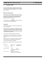
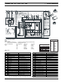
7 Circuit Diagrams
4
1
3
2
3
3
1
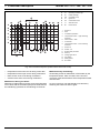
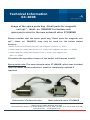
Diagnostic connector
2
Timer P:
with plus to connection 10 = continuous operating during immediate heating
terminal 10 not connected = duration of heating programmable (10 min to 120 min);
3
Pin assignment:
3
3
3
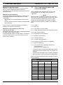
Wire colors
4
Pin assignment
D1
D2
D3
D4
F1
F2
4wire lead
0.75 gr
0.75 or
0.75 gn
0.75 br
not used
not used
7wire lead
0.75 rt
0.75 or
0.75 bl
2.0 br
2.0 sw
2.0 rt/ws
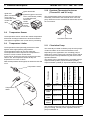
Wire gauges
< 7.5 m
7.5 - 15 m
0.75 mm2
1.0 mm2
1.5 mm2
2.5 mm2
4.0 mm2
1.5 mm2
1.5 mm2
2.5 mm2
4.0 mm2
6.0 mm2
bl
br
ge
gn
gr
or
rt
sw
vi
ws
blue
brown
yellow
green
gray
orange
red
black
violet
white
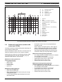
with connection to terminal 61 auxiliary
Item
Nomenclature
A1
Heater
Remark
Item
Nomenclature
Remark
P
Standard timer (1531)
for timed operation
A2
Control unit
SG 1572D
S3
Switch
external trigger circulation pump
B1
Flame sensor
observe polarity
S4
Switch
power save operation
B2
Temperature sensor
polarity optional
U1
Igniter box
B3
Temperature limiter
B4
Thermostat
U2
Igniter electrodes
for nozzle preheating
W1
Wiring harness (1)
B5
Thermostat
alternative to B3
W2
Wiring harness (2)
B6
Thermostat
for vertical installation (MV Y1)
A
Plug connections, 6-pole
E1
Heating cartridge
for nozzle preheating
C
Plug connections, 1-pole
F1
Fuse 5 A
flat fuse DIN 72581 part 3
D
Plug connections, 4-pole
F2
Fuse 25 A
flat fuse DIN 72581 part 3
F
Plug connections, 2-pole
F3
Fuse 25 A
flat fuse DIN 72581 part 3
X1
Plug connections, 6-pole
H1
Light
operation indicator light
X2
Plug connections, 2-pole
H2
Light
flame indicator
X3
Plug connections, 8-pole
H4
Symbol for “Heating”
in Display
symbol lighting (in item P)
X4
Plug connections, 12-pole
Y1
Solenoid valve
M1
Motor
combustion air fan
M2
Motor
circulation pump
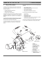
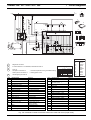
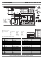
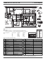
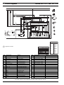
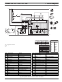
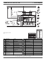
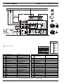
Fig. 704 Automatic Control Circuit with Control Unit 1572D and Standard Timer
705