1
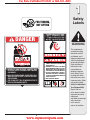
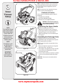
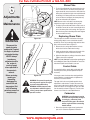
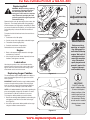
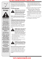
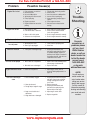
For Parts Call 606-678-9623 or 606-561-4983
Safety • Assembly • Operation • Tips & Techniques • Maintenance • Troubleshooting • Parts Lists • Warranty
OPERATOR’S MANUAL
Single-Stage Snow Thrower
IMPORTANT
READ SAFETY RULES AND INSTRUCTIONS CAREFULLY BEFORE OPERATION
Warning: This unit is equipped with an internal combustion engine and should not be used on or near any unimproved forest-covered, brushcovered or grass-covered land unless the engine’s exhaust system is equipped with a spark arrester meeting applicable local or state laws (if any).
If a spark arrester is used, it should be maintained in effective working order by the operator. In the State of California the above is required by law
(Section 4442 of the California Public Resources Code). Other states may have similar laws. Federal laws apply on federal lands. A spark arrester
for the muffler is available through your nearest engine authorized service dealer or contact the service department, P.O. Box 361131 Cleveland,
Ohio 44136-0019.
PRINTED IN U.S.A.
MTD LLC, P.O. BOX 361131 CLEVELAND, OHIO 44136-0019
www.mymowerparts.com
FORM NO. 769-02571
6/06/2006
For Parts Call 606-678-9623 or 606-561-4983
This Operator’s Manual is an important part of your new snow thrower. It will help you assemble,
prepare and maintain the unit for best performance. Please read and understand what it says.
Table of Contents
Safety Labels............................................ p. 3
Safe Operation Practices........................ p. 4
Setting Up Your Snow Thrower............... p. 6
Know Your Snow Thrower....................... p. 7
Operating Your Snow Thrower................ p. 8
Adjustments & Maintenance................. p. 10
Off-Season Storage............................... p. 12
Troubleshooting..................................... p. 13
Parts List................................................ p. 14
Accessories & Kits................................ p. 18
Notes....................................................... p. 19
Warranty......................................Back Cover
Finding and Recording Model Number
BEFORE ASSEMBLING YOUR NEW EQUIPMENT,
please locate the model plate on the equipment and
copy the information to the sample model plate provided to the right. You can locate the model plate by
standing at the operating position and looking down
at the rear of the deck. This information will be necessary to use the manufacturer’s web site, to obtain
assistance from the Customer Support Department,
or when contacting an authorized service dealer.
Model Number
Serial Number
MTD LLC
P. O. BOX 361131
www.whiteoutdoor.com CLEVELAND,OH 44136
DEALER LOCATOR PHONE NUMBER: 800-949-4483
Customer Support
If you have difficulty assembling this product or have any questions regarding the controls, operation, or
maintenance of this unit, you can seek help from the experts. To reach a local White Outdoor dealer or
retailer, visit www.whiteoutdoor.com or call our Dealer Locator line at 1-800-949-4483.
Engine Information
The engine manufacturer is responsible for all engine-related issues with regard to performance, power-rating,
specifications, warranty and service. Please refer to the engine manufacturer’s Owner’s/Operator’s Manual
packed separately with your unit for more information.
www.mymowerparts.com
For Parts Call 606-678-9623 or 606-561-4983
1
FOR TURNING,
NOT LIFTING
Safety
Labels
AVOID INJU RY FROM
ROTAT I N G A U G E R KEEP HANDS , FEET
AND CLOTHING AWAY.
DANGER
WARNING
NEVER PUT HAND IN CHUTE. CONTACT WITH
ROTATING PARTS CAN AMPUTATE FINGERS
AND HANDS.
SHUT OFF ENGINE AND WAIT UNTIL AL L
MOVING PARTS HA VE STOPPED BEFORE
UNCLOGGING.
USE CLEAN-OUT TOOL OR WOODEN STICK TO
UNCLOG DISCHARGE CHUTE.
1. KEEP AWAY FROM RO TATING AUGER
CONTACT WITH AUGER CAN AMPU TATE
HANDS AND FEE T.
2. DISENGAGE CLUTCH LEVERS, STOP ENGINE,
AND REMAIN BEHIND HANDLES UNTIL ALL
MOVING PARTS HAVE STOPPED BEFORE
UNCLOGGING OR SERVICING MACHINE .
3. TO AVOID THROWN OBJECTS INJURIES ,
NEVER DIRECT DISCHARGE AT BYSTANDERS.
USE EXTRA CAUTION WHEN OPERATING ON
GRAVEL SURFACES.
4. READ OPERATOR'S MANUAL.
This symbol points
out important safety
instructions which, if
not followed, could
endanger the personal
safety and/or property
of yourself and others.
Read and follow all
instructions in this
manual before attempting to operate
this machine. Failure
to comply with these
instructions may result
in personal injury. When
you see this symbol.
HEED ITS WARNING!
Your Responsibility
Restrict the use
of this power machine
to persons who read,
understand
and follow the warnings
and instructions
in this manual
and on the machine.
www.mymowerparts.com
For Parts Call 606-678-9623 or 606-561-4983
2
Safe
Operation
Practices
WARNING
This symbol points
out important safety
instructions which, if
not followed, could
endanger the personal
safety and/or property
of yourself and others.
Read and follow all
instructions in this
manual before attempting to operate
this machine. Failure
to comply with these
instructions may result
in personal injury. When
you see this symbol.
WARNING: Engine Exhaust, some of its constituents, and certain vehicle components contain or emit chemicals known to State of California to cause cancer and
birth defects or other reproductive harm.
DANGER: This machine was built to be operated according to the rules for safe operation in this
manual. As with any type of power equipment, carelessness or error on the part of the operator can
result in serious injury. This machine is capable of amputating hands and feet and throwing objects.
Failure to observe the following safety instructions could result in serious injury or death.
Training
Preparation
1. Read, understand, and follow all instructions on the
machine and in the manual(s) before attempting to
assemble and operate. Keep this manual in a safe place for
future and regular reference and for ordering replacement
parts.
2. Be familiar with all controls and their proper operation.
Know how to stop the machine and disengage them quickly.
3. Never allow children under 14 years old to operate this
machine. Children 14 years old and over should read and
understand the operation instructions and safety rules in
this manual and should be trained and supervised by a
parent.
4. Never allow adults to operate this machine without proper
instruction.
5. Thrown objects can cause serious personal injury. Plan
your snow-throwing pattern to avoid discharge of material
toward roads, bystanders and the like.
6. Keep bystanders, helpers, pets and children at least 75 feet
from the machine while it is in operation. Stop machine if
anyone enters the area.
7. Exercise caution to avoid slipping or falling, especially
when operating in reverse.
1. Thoroughly inspect the area where the equipment is to be
used. Remove all doormats, newspapers, sleds, boards,
wires and other foreign objects, which could be tripped over
or thrown by the auger/impeller.
2. Always wear safety glasses or eye shields during operation
and while performing an adjustment or repair to protect your
eyes. Thrown objects which ricochet can cause serious
injury to the eyes.
3. Do not operate without wearing adequate winter outer
garments. Do not wear jewelry, long scarves or other
loose clothing, which could become entangled in moving
parts. Wear footwear which will improve footing on slippery
surfaces.
4. Use a grounded three-wire extension cord and receptacle
for all units with electric start engines.
5. Adjust collector housing height to clear gravel or crushed
rock surfaces.
6. Disengage all control levers before starting the engine.
7. Never attempt to make any adjustments while engine is
running, except where specifically recommended in the
operator’s manual.
8. Let engine and machine adjust to outdoor temperature
before starting to clear snow.
9. To avoid personal injury or property damage use extreme
care in handling gasoline. Gasoline is extremely flammable
and the vapors are explosive. Serious personal injury can
occur when gasoline is spilled on yourself or your clothes,
which can ignite. Wash your skin and change clothes
immediately.
a. Use only an approved gasoline container.
b. Extinguish all cigarettes, cigars, pipes and other sources
of ignition.
c. Never fuel machine indoors.
d. Never remove gas cap or add fuel while the engine is hot
or running.
e. Allow engine to cool at least two minutes before refueling.
f. Never over fill fuel tank. Fill tank to no more than ½ inch
below bottom of filler neck to provide space for fuel
expansion.
g. Replace gasoline cap and tighten securely.
h. If gasoline is spilled, wipe it off the engine and equipment. Move machine to another area. Wait 5 minutes
before starting the engine.
i. Never store the machine or fuel container inside where
there is an open flame, spark or pilot light (e.g. furnace,
water heater, space heater, clothes dryer etc.).
j. Allow machine to cool at least 5 minutes before storing.
HEED ITS WARNING!
Your Responsibility
Restrict the use
of this power machine
to persons who read,
understand
and follow the warnings
and instructions
in this manual
and on the machine.
www.mymowerparts.com
For Parts Call 606-678-9623 or 606-561-4983
Operation
Maintenance & Storage
1. Do not put hands or feet near rotating parts, in the
auger/impeller housing or chute assembly. Contact with the
rotating parts can amputate hands and feet.
2. The auger/impeller control lever is a safety device. Never
bypass its operation. Doing so makes the machine unsafe
and may cause personal injury.
3. The control levers must operate easily in both directions
and automatically return to the disengaged position when
released.
4. Never operate with a missing or damaged chute assembly.
Keep all safety devices in place and working.
5. Never run an engine indoors or in a poorly ventilated area.
Engine exhaust contains carbon monoxide, an odorless and
deadly gas.
6. Do not operate machine while under the influence of alcohol
or drugs.
7. Muffler and engine become hot and can cause a burn. Do
not touch.
8. Exercise extreme caution when operating on or crossing
gravel surfaces. Stay alert for hidden hazards or traffic.
9. Exercise caution when changing direction and while operating on slopes.
10.Plan your snow-throwing pattern to avoid discharge towards
windows, walls, cars etc. Thus, avoiding possible property
damage or personal injury caused by a ricochet.
11.Never direct discharge at children, bystanders and pets or
allow anyone in front of the machine.
12.Do not overload machine capacity by attempting to clear
snow at too fast of a rate.
13.Never operate this machine without good visibility or light.
Always be sure of your footing and keep a firm hold on the
handles. Walk, never run.
14.Disengage power to the auger/impeller when transporting or
not in use.
15.Never operate machine at high transport speeds on slippery
surfaces. Look down and behind and use care when
backing up.
16.If the machine should start to vibrate abnormally, stop the
engine, disconnect the spark plug wire and ground it against
the engine. Inspect thoroughly for damage. Repair any
damage before starting and operating.
17.Disengage all control levers and stop engine before you
leave the operating position (behind the handles). Wait
until the auger/impeller comes to a complete stop before
unclogging the chute assembly, making any adjustments, or
inspections.
18.Never put your hand in the discharge or collector openings.
Always use the clean-out tool provided to unclog the discharge opening. Do not unclog chute assembly while engine
is running. Shut off engine and remain behind handles until
all moving parts have stopped before unclogging.
19.Use only attachments and accessories approved by the
manufacturer (e.g. wheel weights, tire chains, cabs etc.).
20.If situations occur which are not covered in this manual,
use care and good judgment. Contact your local authorized
service dealer.
1. Never tamper with safety devices. Check their proper
operation regularly. Refer to the maintenance and adjustment sections of this manual.
2. Before cleaning, repairing, or inspecting machine disengage all control levers and stop the engine. Wait until the
auger/impeller come to a complete stop. Disconnect the
spark plug wire and ground against the engine to prevent
unintended starting.
3. Check bolts and screws for proper tightness at frequent
intervals to keep the machine in safe working condition.
Also, visually inspect machine for any damage.
4. Do not change the engine governor setting or over-speed
the engine. The governor controls the maximum safe
operating speed of the engine.
5. Snow thrower shave plates and skid shoes are subject to
wear and damage. For your safety protection, frequently
check all components and replace with original equipment
manufacturer’s (OEM) parts only. “Use of parts which do
not meet the original equipment specifications may lead to
improper performance and compromise safety!”
6. Check controls periodically to verify they engage and
disengage properly and adjust, if necessary. Refer to the
adjustment section in this operator’s manual for instructions.
7. Maintain or replace safety and instruction labels, as necessary.
8. Observe proper disposal laws and regulations for gas, oil,
etc. to protect the environment.
9. Prior to storing, run machine a few minutes to clear snow
from machine and prevent freeze up of auger/impeller.
10.Never store the machine or fuel container inside where
there is an open flame, spark or pilot light such as a water
heater, furnace, clothes dryer etc.
11.Always refer to the operator’s manual for proper instructions
on off-season storage.
Do not modify engine
To avoid serious injury or death, do not modify engine in any
way. Tampering with the governor setting can lead to a runaway
engine and cause it to operate at unsafe speeds. Never tamper
with factory setting of engine governor.
Notice regarding Emissions
Engines which are certified to comply with California and federal
EPA emission regulations for SORE (Small Off Road Equipment)
are certified to operate on regular unleaded gasoline, and may
include the following emission control systems: Engine Modification (EM) and Three Way Catalyst (TWC) if so equipped.
Your Responsibility
Restrict the use of this power machine to persons who read, understand and follow the warnings and instructions in this manual
and on the machine.
www.mymowerparts.com
2
Safe
Operation
Practices
WARNING
This symbol points
out important safety
instructions, which if
not followed, could
endanger the personal
safety and/or property
of yourself and others.
Read and follow all
instructions in this manual before attempting to
operate this machine.
Failure to comply with
these instructions may
result in personal injury.
When you see this
symbol.
HEED IT’S WARNING!
Your Responsibility
Restrict the use
of this power machine
to persons who read,
understand
and follow the warnings
and instructions
in this manual
and on the machine.
3
For Parts Call 606-678-9623 or 606-561-4983
NOTE: This Operator’s Manual covers several models.
Snow thrower features vary by model. Not all features
discussed in this manual are applicable to all snow
thrower models.
1
NOTE: All references to left or right side of the snow
thrower is from the operating position only
Snow
Thrower
Setup
Contents of Carton
Carton contents are listed below with part numbers in
parentheses.
1. Two Ignition Keys (725-0201)
2
2. 20 oz. Bottle 5-30W Oil (737-0209)
3. Extension Cord (if so equipped) (629-0071)
WARNING: Disconnect the spark plug
wire and ground it against the engine to
prevent unintended starting.
Figure 3-1
NOTE:
This Operator’s Manual
covers several models.
Snow thrower features
vary by model. Not
all features discussed
in this manual are
applicable to all snow
thrower models.
Positioning the Upper Handle
NOTE: Remove packing material, if present.
2
2. Tighten the wing knobs to secure the handle in place
as in Figure 3-1.
Assembling the Discharge Chute
For shipping reasons, the snow thrower has been
packaged with the upper chute pivoted all the way down.
To pivot it upward, proceed as follows:
3
NOTE:
All references to left
or right side of the
snow thrower is
from the operating
position only.
IMPORTANT:
Do not use the
chute handle to lift
the snow thrower.
1. Making sure not to pinch the cable in the process,
pivot the upper handle into the operating position as
illustrated in Figure 3-1 until it clicks into place.
NOTE: Turn the chute until the chute opening is facing
straight ahead.
1
1. Remove the wing knob, flat washer and carriage bolt
from the lower chute. See Figure 3-2.
Figure 3-2
2. Pivot the upper chute upward over the lip on the lower
chute so that there is NO gap between the upper
chute and the lower chute.
Chute Handle
3. Re-secure with the hardware just removed. If installed
correctly, your snow thrower should look like Figure
3-3.
IMPORTANT: Do not use the chute handle to lift the
snow thrower
Figure 3-3
www.mymowerparts.com
For Parts Call 606-678-9623 or 606-561-4983
Auger Control Handle
Recoil Starter
Know
Your Snow
Thrower
Key
Primer
Gasoline Cap
4
Electric
Starter
Button
Chute Assembly
Choke Lever
Spark Plug Access
Shave Plate
Oil Fill
Auger
IMPORTANT:
This unit is shipped
without oil in the
engine. Oil is packaged
separately with this unit
and must be added per
the engine owner’s
manual instructions.
Figure 4-1
Choke Lever
OFF
Auger
CHOKE
ON
Activating choke control closes the choke plate on
carburetor and aids in starting engine. Refer to the engine
manual packed with unit for more detailed instructions.
Depressing primer forces fuel directly into
engine’s carburetor to aid in cold-weather
starting. Refer to engine manual packed with
unit for more detailed instructions.
Ignition Key
Ignition key must be present, inserted in
key switch, and in the “ON” position for
engine to start.
Recoil Starter
PRIMER
PRIMER
PRIMER
Primer
PUSH FOR A
COLD ENGINE
OFF
Stop
ON
Run
IGNITION
The starter handle is used to manually start the engine.
Electric Starter Button (If so equipped)
Pressing the electric starter button engages the engine’s
electric starter when plugged into a 120V power source
Electric Starter Plug (If so equipped)
Requires use of a two-prong outdoor extension cord
(packed with the snow thrower) and a 120V power
source/wall outlet.
Spark Plug Cover
Remove spark plug cover to access spark plug.
When engaged, the augers rotation draws snow into the
auger housing and throws it out the discharge chute.
Rubber paddles on the augers also aid in propelling the
unit as they come in contact with the pavement.
Auger Control Handle
Located on the upper handle, the auger control handle
is used to engage and disengage drive to the auger.
Squeeze the control handle against the upper handle to
engage auger; release it to disengage.
Discharge Chute / Chute Handle
Rotate the discharge chute to the left or right using
chute handle. Pitch of the discharge chute controls
angle at which the snow is thrown. Loosen wing knob
on side of the discharge chute before pivoting discharge
chute upward or downward. Retighten the knob once
desired position has been achieved.
Shave Plate
The shave plate maintains contact with pavement as
the snow thrower is propelled, allowing snow close to
pavement’s surface to be discharged.
Gasoline Cap
Remove gas cap to add fuel. Unit runs on regular gas.
Oil Fill
Remove cap to add oil. Refer to engine owner’s manual
packed with this unit for instructions on adding oil.
www.mymowerparts.com
NOTE:
This unit may
include a fuel plug,
which is only used
during assembly to
keep dirt and debris out
of fuel tank. Discard
the fuel plug before
filling the
fuel tank.
5
Operation
For Parts Call 606-678-9623 or 606-561-4983
Recoil Starter
Key
Primer
Gasoline Cap
Electric
Starter
Button
WARNING
WARNING:
Read, understand,
and follow all
instructions and
warnings on the
machine and in
this manual before
operating.
Use extreme care
when handling
gasoline. Gasoline is
extremely flammable
and the vapors are
explosive. Never fuel
the machine indoors
or while the engine
is hot or running.
Extinguish cigarettes,
cigars, pipes and
other sources of
ignition.
The electric starter
must be used with a
properly grounded
three-prong
receptacle at all
times to avoid the
possibility of electric
shock. Follow all
instructions carefully
prior to operating the
electric starter.
Choke Lever
Spark Plug Access
Oil Fill
Figure 5-1
Before Starting
Electric Starter (if so equipped)
WARNING: Read, understand, and
follow all instructions and warnings on
the machine and in this manual before
operating.
WARNING: The electric starter must
be used with a properly grounded
three-prong receptacle at all times to
avoid the possibility of electric shock.
Follow all instructions carefully prior to
operating the electric starter.
IMPORTANT: For complete and detailed engine
starting, stopping and storing instructions, it is recommended that you read the engine manual also included
with this unit.
1. The electric starter is equipped with a grounded threewire power cord and plug, and is designed to operate
on 120 volt AC household current.
1. The spark plug wire was disconnected for safety.
Attach spark plug wire to spark plug before starting.
2. Determine that your house wiring is a three-wire
grounded system. Ask a licensed electrician if you are
not certain.
Gas and Oil Fill-Up
1. Check oil and gasoline level and add if necessary.
Follow related instructions in the separate engine
manual packed with your snow thrower.
3. If your home wiring system is not a three-wire
grounded system, do not use this electric starter
under any conditions.
WARNING: Use extreme care when
handling gasoline. Gasoline is
extremely flammable and the vapors
are explosive. Never fuel the machine
indoors or while the engine is hot or
running. Extinguish cigarettes, cigars,
pipes and other sources of ignition.
4. If your home electrical system is grounded, but
a three-hole receptacle is not available, one should
be installed by a licensed electrician before using the
electric starter.
5. If you have a grounded three-prong receptacle,
proceed as follows.
6. Move Choke Control to the “Full” position.
To Start Engine
7. Push Primer three (3) times, making sure to cover
vent hole when pushing.
1. To avoid carbon monoxide poisoning, make sure
engine is outdoors in a well-ventilated area.
8. Connect power cord to switch box on dash panel.
Plug the other end of power cord into a three-prong
120-volt, grounded, AC receptacle.
2. Insert ignition key into slot. Turn key to ON position.
3. Now follow the instructions below as it pertains to
your unit. See Figure 5-1 for location of controls.
9. Push starter button to crank engine.
www.mymowerparts.com
For Parts Call 606-678-9623 or 606-561-4983
10.When engine starts, release starter button, and move
choke gradually to 1/2 Choke until the engine runs
smoothly. Next move Choke to OFF. If engine falters,
move choke immediately to FULL and then gradually
to 1/2 then to OFF.
11.Disconnect the power cord. Always unplug from the
outlet first, and then from the snow thrower.
Recoil Starter
1. Move choke lever to FULL choke position (cold engine
start).
2. If engine is warm, place choke in OFF position instead
of FULL.
5. Remove ignition key and disconnect spark plug wire
to prevent accidental starting.
Operating the Snow Thrower
The pitch of the chute assembly controls the angle at
which the snow is thrown.
1. Loosen the wing knob found on the left side of the
chute assembly and pivot the upper chute upward or
downward to the desired pitch. Retighten the wing
knob before operating the snow thrower.
WARNING
4. If engine is warm, push primer button only once.
NOTE: Always cover vent hole in primer button when
pushing. Additional priming may be necessary for first
start if temperature is below 15 degrees Fahrenheit.
WARNING:
Muffler, engine and
surrounding areas
become hot and
can cause a burn.
Do not touch.
5. Grasp starter handle and pull rope out slowly, until it
pulls slightly harder. Let rope rewind slowly.
6. Pull starter handle rapidly. Do not allow handle to snap
back. Allow it to rewind slowly while keeping a firm
hold on the starter handle.
7. As engine warms up and begins to operate evenly,
rotate choke lever slowly to the 1/2 Choke position.
When the engine begins to run smoothly, move the
choke to the OFF position. If engine falters, return
to FULL choke, then slowly move to 1/2 then OFF
position.
Figure 5-2
To Stop Engine
To help prevent possible freeze-up of starter,
proceed as follows:
1. Run engine for a few minutes before stopping to help
dry off any moisture on the engine.
2. Electric Starter: Connect power cord to switch box
on engine, then to 120 volt AC receptacle. With the
engine running, push starter button and spin the
starter for several seconds. The unusual sound made
by spinning the starter will not harm engine or starter.
Disconnect the power cord from receptacle first, and
then from switch box.
Operation
2. Position the chute assembly opening by using the
Chute Handle to throw the snow in the desired
direction. See Figure 5-2.
3. Push Primer three (3) times, making sure to cover
vent hole when pushing.
1. To stop engine, turn ignition key counter-clockwise.
Disconnect the spark plug wire from the spark plug
to prevent accidental starting while equipment is
unattended.
5
Operating Tips
1. Discharge snow downwind whenever possible.
Slightly overlap each previously cleared path.
2. Lifting up on the handle will allow the rubber on the
augers to propel the snow thrower forward. Pushing
downward on the handle will raise the augers off the
ground and stop forward motion.
NOTE: Excessive upward pressure on the handle will
result in premature wear on the rubber auger blades
which would not be covered by warranty.
3. Run the engine for a few minutes before stopping to
help dry any moisture on the engine.
4. Clean the snow thrower thoroughly after each use.
WARNING: Muffler, engine and surrounding areas become hot and can
cause a burn. Do not touch.
3. Recoil Starter: With engine running, pull starter rope with
a rapid, continuous full arm stroke three or four times.
Pulling the starter rope will produce a loud clattering
sound, which is not harmful to the engine or starter.
4. Wipe all snow and moisture from the carburetor cover
in the area of the control levers. Also, move control
levers back and forth several times. Leave choke
control in the FULL choke position.
www.mymowerparts.com
IMPORTANT:
For complete and
detailed engine starting,
stopping and storing
instructions,
it is recommended
that you read the
engine manual also
included with
this unit .
NOTE:
Excessive upward
pressure on the
handle will result in
premature wear
on the rubber
auger blades which
would not be covered
by warranty.
6
For Parts Call 606-678-9623 or 606-561-4983
Shave Plate
Side View
Adjustments
&
Maintenance
NOTE: On new units or units with a new shave plate
installed, the augers may be slightly off the ground.
2. To adjust, tip the snow thrower back so that it rests on
the handle. Loosen the four lock nuts and bolts which
secure the shave plate to the housing. See Figure 6-1.
Move the shave plate to desired position and retighten
the nuts and bolts securely.
Figure 6-1
WARNING
Disconnect the
spark plug wire
and ground it against
the engine to prevent
unintended starting.
Replacing Shave Plate
The shave plate is attached to the bottom of the auger
housing and is subject to wear. It should be checked
periodically. There are two wearing edges and the shave
plate can be reversed. Refer to Figure 6-1.
1. Remove the four carriage bolts and hex lock nuts
which attach it to the snow thrower housing.
2. Install new shave plate, making sure the heads of the
carriage bolts are on the inside of the housing.
3. Adjust the shave plate according to instructions above.
Tighten securely once adjusted.
NEVER attempt
to make any
adjustments while
the engine is
running, except
where specified in
the operator’s
manual.
Before servicing,
repairing, or
inspecting,
disengage the
control bail and
stop engine. Wait
until all moving
parts have come to a
complete stop.
1. To check the adjustment of the shave plate, place the
unit on a level surface. The wheels, shave plate and
augers should all contact level surface. Note that if the
shave plate is adjusted too high, snow may blow under
the housing. If the shave plate wears out excessively,
or the unit does not self-propel, the shave plate may
be too low and needs to be adjusted.
NOTE: Call 1-866-840-6483 for information regarding price
and availability of Shave Plate Kit 753-0451 or contact the
authorized Troy-bilt Service Dealer in your area.
Control Cable
As a result of both the control cable and the drive belt
stretching due to wear, periodic adjustments may be
necessary.
Figure 6-2
WARNING: Disconnect the spark plug
wire and ground it against the engine
to prevent unintended starting.
WARNING: NEVER attempt to make
any adjustments while the engine is
running, except where specified in the
operator’s manual.
If the auger seems to hesitate when rotating while the
engine maintains a constant speed, an adjustment is
necessary. Proceed as follows:
The upper hole in the control handle provides for an
adjustment in cable tension. To adjust, disconnect the
end of control cable from the bottom hole in the control
handle and reinsert it in the upper hole. Insert the cable
from the outside as shown in Figure 6-2. Test the snow
thrower to see if there is a noticeable difference.
Carburetor
WARNING: If any adjustments need to
be made to the engine while the engine
is running (e.g. carburetor), keep
clear of all moving parts. Be careful of
muffler, engine and other surrounding
heated surfaces.
1. Refer to the separate engine manual, packed with
your unit, for carburetor adjustment information
10
www.mymowerparts.com
For Parts Call 606-678-9623 or 606-561-4983
Replacing Belt
WARNING: Before servicing, repairing,
or inspecting, disengage the control
bail and stop engine. Wait until all
moving parts have come to a complete
stop. Disconnect spark plug wire and
ground it against the engine to prevent
unintended starting.
Idler Pulley
Remove the belt cover by removing five hex screws. See
Figure 6-3. Then simply pull the belt off by grasping it
from the bottom of the auger pulley and pulling off. Once
you remove the belt from the pulleys, you can push down
on the idler pulley to release the belt from under belt
keeper.
6
Adjustments
&
Maintenance
Belt Keeper
To replace the belt follow these instructions and refer to
Figure 6-4:
To remove, pull belt here
1. Push down on the Idler pulley.
Figure 6-3
2. Put belt on top of the auger pulley under belt keeper.
3. Thread belt around engine pulley.
WARNING
1
4. Push belt over bottom of auger pulley.
3
Reinstall the belt cover removed earlier.
Engine
1. Refer to the separate engine manual for all engine
maintenance procedures.
2. Check engine and snow thrower frequently for loose
hardware, and tighten as needed.
2
Lubrication
Lubricate pivot points on the control handle and the
extension spring at the end of the control cable with a
light oil once every season and before storage of the
snow thrower at the end of the season.
4
Replacing Auger Paddles
Before servicing,
repairing, or inspecting, disengage the
control bail and stop
engine. Wait until all
moving parts have
come to a complete
stop. Disconnect
spark plug wire and
ground it against the
engine to prevent
unintended starting.
Figure 6-4
The snow thrower auger’s rubber paddles are subject to
wear and should be replaced if any signs of excessive
wear is present.
IMPORTANT: Do NOT allow the auger’s rubber paddles
to wear to the point where portions of the metal auger
itself can come in contact with the pavement. Doing so
can result in serious damage to your snow thrower.
IMPORTANT:
Do NOT allow the
auger’s rubber paddles
to wear to the point
where portions of the
metal auger itself can
come in contact with
the pavement. Doing
so can result in serious
damage to your snow
thrower.
NOTE: Call 1-866-840-6483 for information regarding the
price and availability of Auger Kit 753-04472 or contact
an authorized Troy-bilt Service Dealer in your area.
To change the rubber paddles, proceed as follows:
1. Remove the existing rubber paddles by unthreading the
self-tapping screws which secure them to the auger.
See Figure 6-5.
2. Secure the replacement rubber paddles to the auger
using the hardware removed earlier.
Figure 6-5
11
www.mymowerparts.com
7
Off-Season
Storage
WARNING
Never store snow
thrower with fuel
in tank indoors or
in poorly ventilated
areas, where fuel
fumes may reach an
open flame, spark
or pilot light as on a
furnace, water heater,
clothes dryer or gas
appliance.
Drain fuel into an
approved container
outdoors, away from
any open flame. Be
certain engine is
cool. Do not smoke.
Fuel left in engine
during warm weather
deteriorates and
will cause serious
starting problems.
Do not drain
carburetor if using
fuel stabilizer.
Never use engine or
carburetor cleaning
products in the fuel
tank or permanent
damage may occur.
For Parts Call 606-678-9623 or 606-561-4983
If the snow thrower will not be used for 30 days or
longer, or if it is the end of the snow season when the
last possibility of snow is gone, the equipment needs to
be stored properly. Follow storage instructions below to
ensure top performance from the snow thrower for many
more years.
Preparing Engine
WARNING: Never store snow thrower
with fuel in tank indoors or in poorly
ventilated areas, where fuel fumes
may reach an open flame, spark or
pilot light as on a furnace, water
heater, clothes dryer or gas appliance.
NOTE: It is important to prevent gum deposits from
forming in essential fuel system parts of the engine such
as the carburetor, fuel filter, fuel hose or tank during
storage.
4. Remove the spark plug and pour one (1) ounce
of engine oil through the spark plug hole into the
cylinder. Cover spark plug hole with a rag and crank
the engine several times to distribute the oil. Replace
spark plug.
NOTE: Refer to the engine manual for more information
on preparing the snow thrower engine for storage.
Preparing Snow Thrower
1. When storing the snow thrower in an unventilated or
metal storage shed, care should be taken to rustproof
the equipment. Using a light oil or silicone, coat the
equipment, especially any chains, springs, bearings
and cables.
2. Remove all dirt from exterior of engine and equipment.
3. Follow lubrication recommendations on page 11.
4. Store equipment in a clean, dry area.
CAUTION: Alcohol blended fuels (called gasohol
or using ethanol or methanol) can attract moisture
which leads to separation and formation of acids
during storage. Acidic gas can damage the fuel
system of an engine while in storage.
To avoid engine problems, the fuel system should be
emptied before storage for 30 days or longer. Follow
these instructions to prepare your snow thrower for
storage:
WARNING: Drain fuel into an approved
container outdoors, away from any
open flame. Be certain engine is cool.
Do not smoke. Fuel left in engine
during warm weather deteriorates and
will cause serious starting problems.
1. Remove all gasoline from the carburetor and the fuel
tank to prevent gum deposits from forming on these
parts and harming the engine.
2. Run the engine until the fuel tank is empty and it
stops due to lack of fuel.
3. Drain carburetor by pressing upward on bowl drain,
located below the carburetor cover.
WARNING: Do not drain carburetor if
using fuel stabilizer. Never use engine
or carburetor cleaning products in the
fuel tank or permanent damage may
occur.
NOTE: Fuel stabilizer (such as STA-BIL) is an acceptable alternative in minimizing the formation of fuel gum
deposits during storage. Add stabilizer to gasoline
in fuel tank or storage container. Always follow mix
ratio found on stabilizer container. Run engine at least
10 minutes after adding stabilizer to allow it to reach
the carburetor. Do not drain carburetor if using fuel
stabilizer.
12
www.mymowerparts.com
For Parts Call 606-678-9623 or 606-561-4983
Problem
Engine fails to start
Possible Cause(s)
1. Fuel tank empty, or stale fuel
2. Blocked fuel line
3. Key not in ON position
4. Spark plug wire disconnected
5. Faulty spark plug
6. Engine not primed
7. Engine flooded from excessive
priming
Engine runs erratic
Engine overheats
Loss of power
Excessive vibration
Unit fails to self-propel
1. Unit running on choke
2. Fuel line blocked, or stale fuel
3. Water or dirt in fuel system
4. Carburetor out of adjustment
1. Move choke lever to OFF position.
2. Clean fuel line and fill tank with
fresh, clean gasoline.
3. Refer to engine manual for remedy.
4. Refer to engine manual for remedy.
1. Carburetor out of adjustment
1. Refer to engine manual for instruction.
1. Spark plug wire loose
2. Vent in gas cap plugged
1. Firmly connect spark plug wire.
2. Clear vent.
1. Loose parts or damaged auger
1. Stop engine immediately and
disconnect spark plug wire. Check
for possible damage. Tighten all
bolts and nuts. Repair as needed. If
the problem persists, take unit to an
authorized service dealer.
1. Drive cable out of adjustment
1. Adjust control cable following instructions on page 9 of this manual.
2. Replace drive belt.
2. Drive belt loose or damaged
Augers continue to rotate 1. Cable out of adjustment.
Unit fails to discharge
snow
1. Fill tank with clean fresh gasoline.
2. Clean fuel line
3. Insert key and turn to ON position
4. Connect wire to spark plug.
5. Clean spark plug, readjust gap, or
replace.
6. Prime engine four times.
7. Wait at least ten minutes before
starting.
1. Chute assembly clogged.
2. Shear pin sheared.
3. Foreign object lodged in auger.
4. Auger control cable out of
adjustment.
5. Auger belt loose or damaged.
13
1. Adjust auger control cable as
shown in “Making Adjustments” on
page 10.
1. Stop engine and disconnect spark
plug wire. Clean chute and inside
of auger housing with clean-out
tool or stick.
2. Replace shear pin.
3. Stop engine immediately and
disconnect the spark plug wire.
Remove object from auger.
4. Adjust auger control cable.
5. Replace auger belt.
www.mymowerparts.com
8
TroubleShooting
For parts,
accessories, or
problems please
call your local
White Outdoor
dealer or call our
dealer locator line
to find the dealer
nearest you at
1-800-949-4483
or log onto
whiteoutdoor.com
NOTE:
You will need your
model number and
serial number when
calling your service
dealer, refer to page
2 of this manual for
information regarding
locating and recording
your model and serial
numbers.
For Parts Call 606-678-9623 or 606-561-4983
Model Series 2B5-295
18
55
17
23
8
10
16
7
1
6
11
5
25
24
32
9
39
15
40
12
50
34
49 44
31
29
2
7
27
46
38
48
29
28
41
9
45
43
35
36
20
30
22
29
13
3
26
21
4
19
37
47
14
www.mymowerparts.com
33
For Parts Call 606-678-9623 or 606-561-4983
9
Part List:
REF
NO.
PART No.
DESCRIPTION
Qty.
REF
NO.
PART No.
DESCRIPTION
Qty.
1
629-0071
Extension Cord
1
26
734-04204
Wheel 5 Lug Diamond Design
2
2
710-0409
Hex Screw, 5/16-24 x 1.75
4
27
684-04168
Idler Pulley (1/4” hole)
1
3
710-0627
Hex Screw, 5/16-24 x .75
1
28
735-04033
Rubber Paddle
2
4
710-0654A
Self Tapping Screw, 3/8-16 x 1
2
29
710-0896
Hex Screw, 1/4-20 x .62
24
5
710-0751
Hex Screw, 1/4-20 x .62
1
30
735-04032
Cresent Spiral
4
6
710-1003
Screw, #10-16 x .625
2
31
684-04228
Auger Assembly
1
7
712-04064
Hex Flange Lock Nut, 1/4-20
9
32
710-0642
Hex Screw 1/4-20 x .75 Gr. 5
1
8
726-0154
Push Mount Cable Tie
1
33
710-0653
Self-tapping Screw 1/4-20 x .375
1
9
684-04228
Auger Assembly
1
34
712-0896
Hex Lock Nut 1/4-28
1
10
726-0205
Clamp, Hose
2
35
710-0352
Self-tapping Screw, 1/4-14 x .375”
6
11
731-2825
Knob, Choke
1
36
712-04063
Hex Flange Lock Nut, 5/16-18
1
12
736-0119
Washer, Lock 5/16
4
37
726-0299
Push Cap, 1/2”
2
13
736-0242
Flat Washer .340 x .872 x .060
1
38
750-04571
Shoulder Spacer .260 x .785 x .538
1
Gas Tank Support Wire
14
747-04236
1
39
736-0329
Lock Washer, 1/4
1
15
750-04297B Spacer, Engine
4
40
736-0176
Flat Washer .265 x .938 x .120
1
16
751-0535
Hose, Fuel Line
18
41
741-04188
Ball Bearing .625 x 37 x 12
2
17
751-10023
Tank, Fuel
1
42
684-04227
Auger Assembly Housing
1
18
751-10278
Cap, Fuel
1
43
748-0234
Shoulder Spacer .25
1
19
754-0101A
V-Belt, 1/2
1
44
738-0924A
Carriage Screw 1/4-28
1
20
756-0416B
Pulley Half, .625 ID x 2.25 OD
2
45
790-00249
Bearing Cup
2
21
756-04232
Pulley, 1/2 x 6.0 OD
1
46
790-00238
Idler Brkt. w/ brake (Pulley hole 1/4”)
1
22
790-00216
Bracket, Engine
1
47
790-00045A Belt Cover
1
23
790-00134
Bracket Support Gas Tank
1
48
710-0106
Hex Screw, 1/4-20 x 1.00 Gr. 5
1
24
7511152847
Primer Hose Line
4
49
756-0625
Cable Roller
1
25
7512B1476
Primer
1
50
732-0357A
Extension Spring
1
NOTES: For a proper working machine,
use Factory Approved Parts. V-belts are
designed to engage and disengage safely.
A substitute (non OEM) V-belt can be
dangerous by not disengaging completely.
Snow
Thrower
For parts and/or
accessories
please call our
Dealer Locator line
at 1-800-949-4483
or log onto
whiteoutdoor.com
NOTE:
For painted parts,
please refer to the
list of color codes
below. Please add the
applicable color code,
wherever needed, to
the part number to
order a replacement
part. For instance, if
a part numbered
700-xxxx is painted
powder black, the part
number to order would
be 700-xxxx-0637.
Red Metallic - 0650
Black - 0637
NOTE: Snow thrower features/components vary by model. NOT all parts listed above and pictured on the previous
page are standard equipment.
15
www.mymowerparts.com
For Parts Call 606-678-9623 or 606-561-4983
9
35
22
36
Part List:
Snow
Thrower
25
18
16
24
23
6
For parts and/or
accessories
please call our
Dealer Locator line
at 1-800-949-4483
or log onto
whiteoutdoor.com
4
5
7
3
37
21
2
27
15
26
8
12
4
33
14
30
32
9
34
10
13
5
4
19
17
32
28
28
30
29
30
31
16
www.mymowerparts.com
11
For Parts Call 606-678-9623 or 606-561-4983
REF
NO.
PART NUMBER
DESCRIPTION
Qty.
1
684-04127
Chute Assembly (Incl. Ref. 37-41)
1
2
710-04071
Carriage Bolt 5/16-18 x 1.0”
1
3
710-0451
Carriage Bolt 5/16-18 x 0.750”
1
4
712-04063
Flange Lock Nut, 5/16-18
6
5
720-04072
Star Knob Assembly
1
6
731-04388A
Chute Handle
1
7
731-04426A
Upper Chute
1
8
731-04353
Ring-Lower Chute
1
9
710-04532
Carriage Bolt 5/16-18 x 2.0 Gr. 5
2
10
731-04886
Chute, Adapter 5” Dia
1
11
725-0157
Cable Tie
1
12
732-04111
Chute Adjustment Spring
1
13
747-04159
Bail, Gull Wing
1
14
749-04106
Upper Handle, Gull Wing
1
15
684-0178
Mitten Grip Bracket
1
16
684-04211
Shroud Assembly, Gray (Incl. Spark Plug Cover)
1
17
710-0895
Screw, 1/4-15 x .75
3
18
710-1003
Self-tapping Screw, #10-16 x .625”
5
19
710-1090
Hex Flange Screw, 5/16-18 x 1.25
2
20
710-1882
Hex Flange Screw 5/16-18 x 1.50 Gr. 5
2
21
710-3083
Hex Screw, 5/16-18 x 1.375
1
22
712-0252
Hex Nut 5/8-32 x .12 Special
1
23
725-2018
Key Switch-Electric Start
1
24
736-0225
Lock Washer Internal .625 x 1.058
1
25
736-0400
Flat Washer .194” x .62” x .063
5
26
736-0451
Saddle Washer .320 x .93
1
27
7510009636
Recoil Handle, Mitten
1
28
710-0134
Screw, 1/4-20 x .62
8
29
710-3008
Truss Machine Screw, 5/16-18 x .75
1
30
712-04064
Hex Flange Lock Nut, 1/4-20
9
31
731-1033
Shave Plate, 19.88
1
32
736-0176
Flat Washer .265 x .938 x .120
4
33
746-04237
Control Cable
1
34
749-04114
Lower Handle
1
35
725-0201
Ignition Key
2
36
684-0189
Spark Plug Cover
1
37
731-04127
Lower Chute 5” Dia.
1
17
www.mymowerparts.com
9
Part List:
Snow
Thrower
For parts and/or
accessories
please call our
Dealer Locator line
at 1-800-949-4483
or log onto
whiteoutdoor.com
NOTE:
For painted parts, please
refer to the list of color
codes below. Please add
the applicable color code,
wherever needed, to the
part number to order a
replacement part.
For instance, if a part
numbered 700-xxxx is
painted powder black, the
part number to order would
be 700-xxxx-0637.
Red Metallic - 0650
Black - 0637
For Parts Call 606-678-9623 or 606-561-4983
10
Accessories
& Kits
The following accessories and kits are available for single-stage, two-cycle snow throwers. See
the retailer from which you purchased your snow thrower, or any authorized White Outdoor Service
Dealer. To find the White Outdoor service dealer nearest you, call our dealer locator line at 1-800949-4483 or log onto www.whiteoutdoor.com.
MODEL
DESCRIPTION
OEM-390-986
Electric Start Kit
(fits models with a four-cycle Tecumseh 4 HP or 5 HP engine)
OEM-737-0209
MTD 4-cycle Snow Thrower Oil
Premium 4-cycle snow thrower oil, SAE 5W30, 20oz. easy pour bottle
OEM-754-0101A
Snow Thrower Auger Belt
753-0451
Shave Plate (includes replacement shave plate and hardware)
753-04472
Rubber Auger Kit, Snow Thrower Single Stage
For parts and/or
accessories
please call our
Dealer Locator line
at 1-800-949-4483
or log onto
whiteoutdoor.com
18
www.mymowerparts.com
For Parts Call 606-678-9623 or 606-561-4983
11
NOTES:
Use this page to make
notes and write down
important information.
For parts and/or
accessories
please call our
Dealer Locator line
at 1-800-949-4483
or log onto
whiteoutdoor.com
19
www.mymowerparts.com
For Parts Call 606-678-9623 or 606-561-4983
MANUFACTURER’S LIMITED WARRANTY FOR
The limited warranty set forth below is given by MTD LLC with respect to
new merchandise purchased and used in the United States, its possessions and territories.
“MTD” warrants this product against defects in material and workmanship
for a period of two (2) years commencing on the date of original purchase
and will, at its option, repair or replace, free of charge, any part found to
be defective in materials or workmanship. This limited warranty shall only
apply if this product has been operated and maintained in accordance
with the Operator’s Manual furnished with the product, and has not been
subject to misuse, abuse, commercial use, neglect, accident, improper
maintenance, alteration, vandalism, theft, fire, water, or damage because
of other peril or natural disaster. Damage resulting from the installation or
use of any part, accessory or attachment not approved by MTD for use
with the product(s) covered by this manual will void your warranty as to
any resulting damage.
Normal wear parts are warranted to be free from defects in material and
workmanship for a period of thirty (30) days from the date of purchase.
Normal wear parts include, but are not limited to items such as: batteries,
belts, blades, blade adapters, grass bags, rider deck wheels, seats, snow
thrower skid shoes, shave plates, auger spiral rubber and tires.
HOW TO OBTAIN SERVICE: Warranty service is available, WITH
PROOF OF PURCHASE, through your local authorized service dealer. To
locate the dealer in your area, check your Yellow Pages, or contact MTD
LLC at P.O. Box 361131, Cleveland, Ohio 44136-0019, or call 1-800-9494483 or log on to our Web site at www.whiteoutdoor.com.
This limited warranty does not provide coverage in the following cases:
a.
b.
c.
d.
The engine or component parts thereof. These items may
carry a separate manufacturer’s warranty. Refer to applicable
manufacturer’s warranty for terms and conditions.
Log splitter pumps, valves, and cylinders have a separate one
year warranty.
Routine maintenance items such as lubricants, filters, blade
sharpening, tune-ups, brake adjustments, clutch adjustments,
deck adjustments, and normal deterioration of the exterior finish
due to use or exposure.
Service completed by someone other than an authorized service
dealer.
e.
f.
g.
MTD does not extend any warranty for products sold or exported outside of the United States, its possessions and territories, except those sold through MTD’s authorized channels of export distribution.
Replacement parts that are not genuine MTD parts.
Transportation charges and service calls.
No implied warranty, including any implied warranty of merchantability of fitness for a particular purpose, applies after the applicable
period of express written warranty above as to the parts as identified. No other express warranty, whether written or oral, except as
mentioned above, given by any person or entity, including a dealer
or retailer, with respect to any product, shall bind MTD. During the
period of the warranty, the exclusive remedy is repair or replacement
of the product as set forth above.
The provisions as set forth in this warranty provide the sole and
exclusive remedy arising from the sale. MTD shall not be liable
for incidental or consequential loss or damage including, without
limitation, expenses incurred for substitute or replacement lawn care
services or for rental expenses to temporarily replace a warranted
product.
Some states do not allow the exclusion or limitation of incidental or
consequential damages, or limitations on how long an implied warranty
lasts, so the above exclusions or limitations may not apply to you.
In no event shall recovery of any kind be greater than the amount of the
purchase price of the product sold. Alteration of safety features of the
product shall void this warranty. You assume the risk and liability for
loss, damage, or injury to you and your property and/or to others and their
property arising out of the misuse or inability to use the product.
This limited warranty shall not extend to anyone other than the original
purchaser or to the person for whom it was purchased as a gift.
HOW STATE LAW RELATES TO THIS WARRANTY: This limited warranty gives you specific legal rights, and you may also have other rights
which vary from state to state.
IMPORTANT: Owner must present Original Proof of Purchase to obtain
warranty coverage.
MTD LLC, P.O. BOX 361131 CLEVELAND, OHIO 44136-0019; Phone: 1-800-949-4483
www.mymowerparts.com