1
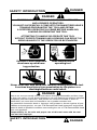
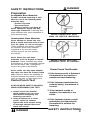
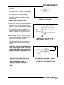
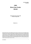
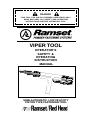
DANGER
THIS TOOL FOR USE BY LICENSED OPERATORS ONLY.
READ AND OBEY ALL SAFETY AND OPERATING
INSTRUCTIONS BEFORE OPERATING TOOL.
VIPER TOOL
OPERATOR’S
SAFETY &
OPERATING
INSTRUCTION
MANUAL
SEMI-AUTOMATIC, LOW VELOCITY
PISTON TYPE FASTENING TOOL
DANGER
SAFETY INTRODUCTION
DANGER
THIS TOOL IS TO BE USED ONLY BY PROPERLY TRAINED
AND LICENSED OPERATORS.
YOU MUST SUCCESSFULLY COMPLETE ITW RAMSET/RED HEAD’S
TRAINING PROGRAM FOR THE TOOL AND OBTAIN
A CERTIFIED OPERATOR’S LICENSE BEFORE HANDLING,
LOADING OR OPERATING THIS TOOL.
ATTEMPTING TO HANDLE OR OPERATE THIS TOOL
WITHOUT PROPER TRAINING AND LICENSING CAN RESULT IN
SERIOUS INJURY TO THE OPERATOR OR BYSTANDERS.
Operator’s and bystanders
must wear eye and hearing protection.
Read manual before
operating tool.
Never close tool with hand over fastener loading end of the tool.
A serious hand injury from penetration by the piston or a
discharged fastener could result.
DANGER
Just as no one can merely read a book about driving an automobile and then hope
to drive one safely, no one should attempt to use any Ramset tool without adequate,
competent personal instruction. And just as one must be licensed to drive an
automobile, one must also be licensed to use a powder actuated tool.
No automobile instruction book or instructor can forewarn a learner against all possibilities and emergencies, nor can ITW Ramset/Red Head instructors and printed
material detail all possible conditions surrounding the use of ITW Ramset/Red Head
tools and products.
Responsibility for the safe and proper use of this tool rests with the tool
user and the employer.
SAFETY INTRODUCTION
2
DANGER
SAFETY INSTRUCTIONS
DANGER
Preparation
Acceptable Base Materials
Powder actuated fastening is suitable for use in the following base
materials only:
• Poured Concrete
• Structural Steel
• Masonry Joints ( see page 8)
Never attempt to fasten into any
other type of material. Fastening into
other materials can cause blindness or
other serious injury.
NEVER FASTEN INTO VERY
HARD OR BRITTLE MATERIALS
Unacceptable Base Materials
Never attempt to fasten into very
hard or brittle materials such as cast
iron, tile, glass, or rock of any type.
These materials can shatter, causing
the fastener and/or base material
fragments to fly free and cause
serious injury to the tool operator
and others.
Never fasten into soft base
materials, such as drywall or lumber
products. These materials may allow
the fastener to travel completely through
and out the other side, endangering
those in the path of the fastener.
Never fasten into any base material
that does not pass the Center Punch
test. Failure to assure the suitability of
the base material can result in serious
injury to the eyes or other body parts.
Center Punch Test
ALWAYS WEAR SAFETY GOGGLES
WHEN PERFORMING THIS TEST.
1. Always check the material
being fastened into for hardness before attempting any
fastening operation.
2. Using a fastener as a center
punch, strike the fastener
against the work surface using
an average hammer blow and
check the results.
DANGER
NEVER FASTEN INTO SOFT
MATERIALS SUCH AS DRYWALL
Center Punch Test Results
1. If the fastener point is flattened,
the material is too hard for a
powder actuated fastening.
2. If the fastener penetrates the
material easily, the material is
too soft.
3. If the material cracks or
shatters, the material is too
brittle.
4. If the fastener makes a small
indentation into the material,
the material is suitable for
fastening.
SAFETY INSTRUCTIONS
3
DANGER
SAFETY INSTRUCTIONS
Loads & Load Selection Safety
1. Always make a test fastening
after being sure that the base
material is suitable for powder
actuated fastening. Failure to
determine the correct power level
to be used may result in the use
of excessive power, allowing the
fastener to pass completely
through the work material,
causing serious or fatal injuries to
others who may be in the path of
the fastener.
2. Color-blind operators must always select loads by load number
to prevent use of an incorrect
load for the same reasons as in #1
above.
Workplace Safety
1. Operators and bystanders must
always wear approved safety
goggles and approved hearing
protection. Failure to do so may
result in blindness or serious eye
injury from flying debris and loss
of hearing from constant or
repeated unprotected exposure to
fastening noise.
2. Always keep the work area clear
of bystanders and unnecessary
materials that could interfere with
safe tool operation. Operating the
tool in a congested or cluttered
area may affect your ability to
operate the tool safely.
3. Never operate tool if flammable or
explosive materials are nearby.
Powder loads burn and create
sparks when fired and could ignite
these materials or fumes.
4. Always post warning signs within
50’ of the area where fastening is
to be done. Sign must state:
“Caution- Powder Actuated Tool
In Use”. Failure to warn others may
result in serious injury to them. Contact ITW Ramset/ Red Head at
1-800-354-7432 to obtain this sign.
SAFETY INSTRUCTIONS
4
ALWAYS MAKE A TEST
FASTENING
4
COLOR-BLIND OPERATORS
MUST ALWAYS SELECT
LOADS BY NUMBER
KEEP WORK AREA CLEAR OF
BYSTANDERS AND CLUTTER
NEVER OPERATE TOOL
AROUND FLAMMABLE OR
EXPLOSIVE MATERIALS
ALWAYS POST WARNING SIGNS
DANGER
DANGER
SAFETY INSTRUCTIONS
Tool Handling Safety
1. Always be sure tool is operating
properly before attempting to
use it. Follow the “Daily
Function Check” shown to the
right and described on page 9.
2. Always load tool using a load
strip selected directly from a box
indicating the power load type
and number. Never attempt to use
loose strip loads that could be
mis-identified.
3. Never carry loose strip loads in
pockets with pins or other hard
objects.
4. Never load a tool unless you
intend to immediately make a
fastening. Loading a tool and
leaving it unattended in the work
area can result in the tool being
accidentally discharged by others.
5. Never place your hand or any
other body part over the fastener
loading end of the tool. Serious
hand injury could result from being
struck by either a fastener or the tool
piston should the tool be accidentally
fired.
6. Always store the tool unloaded
and keep the tool and the loads
securely locked in a tool box.
Keep keys away from children
and unlicensed persons.
7. Always keep the tool pointed
away from yourself and others.
8. Never carry a loaded tool around
the work area.
9. Never allow anyone not trained to
use the tool.
10.Never engage in horseplay with
the tool.
11.Using tool in poorly ventilated
areas, cleaning tool or handling
loads may result in exposure to
lead or other substances known
to cause birth defects, and other
physical harm. Have adequate
ventilation at all times and wash
thoroughly after exposure.
DANGER
ALWAYS DO A DAILY
FUNCTION CHECK BEFORE
LOADING TOOL
NEVER LOAD TOOL UNLESS IT
IS TO BE USED IMMEDIATELY
NEVER PLACE HANDS OR
BODY OVER MUZZLE OPENING
KEEP TOOL LOCKED & OUT OF
THE REACH OF CHILDREN
SAFETY INSTRUCTIONS
5
DANGER
FAILURE TO FOLLOW
INSTRUCTIONS CAN CAUSE
INJURY TO THE TOOL OPERATOR OR TO BYSTANDERS.
SAFETY INSTRUCTIONS
Fastener Driving Safety
1. Only use the tool for fastening
into a suitable base material.
2. Never fire the tool without a
fastener. Firing a tool without a
fastener will cause the piston to
strike the work surface, and may
cause serious injury to you and
others in the work area.
3. Always use the spall guard
whenever possible to minimize
flying particles or debris.
4. Always hold the tool perpendicular to and firmly against the
work surface when making a
fastening. Failure to do so could
allow a fastener to ricochet.
5. Never attempt to drive a fastener
close to an edge or to another
fastener. See page 8 for guidelines.
6. Always use the correct piston
and nosepiece for the fastener
being used. Failure to do so can
result in serious injury to the
user and bystanders.
ALWAYS FOLLOW THE MISFIRE
PROCEDURE
If tool does not fire after the normal
firing sequence, continue to hold the
depressed tool against the work
surface for at least 30 seconds. Then
carefully lower the tool, remove the load
strip and put it in a can of water or other
non-flammable liquid. Never carelessly
discard a strip with live loads into a trash
container.
If the tool becomes stuck or jammed
with a live powder load, keep the tool
pointed in a safe direction, and immediately tag it, “Danger-defective-do not
use”. Lock the tool in a tool box and call
your local Ramset Distributor for assistance.
SAFETY INSTRUCTIONS
6
USE SPALL GUARD
WHENEVER POSSIBLE
ALWAYS HOLD THE TOOL
PERPENDICULAR TO
THE WORK SURFACE
NEVER DRIVE A FASTENER
CLOSE TO AN EDGE
HOLD THE TOOL FIRMLY
AGAINST THE WORK SURFACE
FOR AT LEAST 30 SECONDS.
DANGER
FASTENERS / LOADS
Your Ramset Viper tool uses only the Ramset fasteners and loads shown
below or listed for the tool in the Product Catalog.
DANGER
Never use any other types of fasteners or strip loads in the Viper tool.
Use of other types of fasteners or loads may cause unintentional load discharge,
damage the tool, cause poor fastening performance, or create a risk of seroius
injury to the operator or bystanders.
FASTENERS AND FASTENER ASSEMBLIES
CEILING CLIP ASSEMBLIES - .300 HEAD DIA.
CAT. NO.
2202
SDC100
SDC125
SPC100*
SPC114*
SHANK DIA.
.145
.145
.145
.150/.180
.150/.180
LENGTH
1 1/4”
1”
1 1/4”
1”
1 1/4”
Note: * For Hard Concrete
LOADS
Ramset RS 27 strip loads are specially made for use in the Viper
Tool.
RS 27 10 SHOT
STRIP LOAD
POWER CATALOG
LEVEL
NUMBER
3
4
5
3RS27
4RS27
5RS27
LOAD
CASE
COLOR COLOR
Green
Yellow
Red
Brass
Brass
Brass
The power level of the loads is indicated by the number marked
on each box, the color of the box and the color on the tip of each
load. As the number increases, the power level also increases.
Always peform the center punch test described on page 3 to test
the base material.
Always make a test fastening using the # 3, Green power level
first. If more power is required to set the fastener, use the next
higher power level necessary to drive the fastener is reached
FASTENERS / LOADS
7
FASTENING APPLICATIONS
FASTENING APPLICATIONS
Your Ramset tool can be used for a wide
range of fastening needs in a variety of
base materials. Reading and following
these important fastening guidelines will
help you get the best results from your
tool, fasteners, and powder loads, as
well as help you perform these fastening
operations safely and effectively.
SPACING - FASTENING
INTO CONCRETE
Powder actuated fastenings are permanent fastenings so attempting to
remove a fastener from concrete or
steel may result in a serious injury.
Fastening to Concrete
When fastening into concrete, always
maintain a minimum spacing of 3"
between fastenings and 3" from any
free edge. Concrete thickness should
be at least three times the intended
penetration depth into the concrete.
FASTENER LOCATIONS IN
LIGHTWEIGHT PAN DECK
Driving fasteners too close to an edge
or too close to each other can cause
the concrete edge to fail or fasteners to
fly free.
FASTENER LOCATION IN
PRECAST CONCRETE
Fastening to Steel
Your Ramset tool can be used for
fastening on the flat surfaces of
structural steel.When fastening into
steel, always maintain a minimum
spacing of 1-1/2" between fastenings
and 1/2" from any edge.
PENETRATION INTO CONCRETE
SPACING IN STEEL
FASTENING APPLICATIONS
8
TOOL OPERATING INSTRUCTIONS
TOOL OPERATION
Daily Function Test
Always check the tool first to make
sure that it does not contain a load
strip or fastener.
Test the tool overhead several times by
completely depressing it on a hard
surface. You should hear an audible click
as the firing pin releases. Let up on the
tool and check to be sure that the barrel
assembly has opened to the starting
position.
Next, place the tool, pointing downward,
on a hard surface and firmly, completely
depress the tool. You must not hear the
firing pin release! If the firing pin
releases, STOP, DO NOT TRY TO USE
THE TOOL UNTIL THE PROPER
REPAIRS HAVE BEEN MADE. Contact
your Ramset Distributor for repairs.
OPERATING THE VIPER TOOL
1. Insert a fastener assembly into the
muzzle bushing end of the tool until
it is fully seated. If a clip assembly is
being used, be sure it is positioned
in the cutout section of the spall
guard.
2. Insert a load strip into the bottom of
the handle and push it in until your
finger is in firm contact with the
handle recess. Never try to insert
a load strip into the tool from
the top of the receiver.
3. Carefully raise the tool to the ceiling and depress the barrel
assembly where the fastening is to
be made. Hold the tool perpendicular and forcibly push upwards on
the pole handle to compress the
firing pin spring and release the
sear to fire the tool. If the tool
does not fire, continue to hold it
in place for at least 30 seconds
and then follow the misfire
procedure on page 6. Always
point the tool in a safe direction and
use care when raising it to the
ceiling to avoid bumping objects that
could cause the tool to fire.
PERFORM FUNCTION TEST
WITH EMPTY, UNLOADED TOOL
INSERT FASTENER INTO THE
MUZZLE END OF THE TOOL
INSERT LOAD STRIP INTO THE
OPENING IN THE BOTTOM OF
THE HANDLE
RAISE TOOL TO THE CEILING
AND DEPRESS THE BARREL
ASSEMBLY. THEN PUSH UP
FORCIBLY AGAINST THE WORK
SURFACE TO FIRE THE TOOL
TOOL OPERATING INSTRUCTIONS
9
TOOL OPERATING INSTRUCTIONS
4. Lower the tool, keeping it pointed in
a safe direction, and insert the next
fastener or fastener assembly.
Note: While the Viper tool is being
closed and fired, the advance lever
cam has caused the load advance
lever to be indexed downward to
pick up the next load. When the tool
is lowered and opens up, the next
unfired load is indexed upward to
the firing position. At the same time,
as the tool is lowered, the piston is
automatically reset for the next
fastening.
INSERT THE NEXT FASTENER OR
FASTENER ASSEMBLY INTO THE
MUZZLE BUSHING
NEVER PLACE YOUR HAND OR
FINGERS OVER THE MUZZLE
BUSHING WHILE AN UNFIRED
LOAD IS IN POSITION TO BE
FIRED.
5. After all 10 loads in the strip have
been fired, pull the used load strip
from the top of the tool. NEVER try
to pull a load strip from the bottom
of the tool.
REMOVE THE LOAD STRIP FROM
THE TOP OF THE TOOL
6. If you are working in an area where
dirt or debris can fall onto the tool
while making fastenings, check the
tool frequently to be sure the
muzzle bushing and load strip track
are clear.
CHECK THE MUZZLE BUSHING AND
LOAD STRIP TRACK FOR DEBRIS
NOTE: Use of partially used load strips.
The design of the Viper tool is such that the next load to be fired is
automatically indexed into the firing position during the tool closing, firing
and tool opening sequence of operation. If it is necessary to use a
partially used load strip, the end of the strip containing the live loads
should be placed into the bottom of the tool handle just as if it were a new
strip. By counting the number of unfired loads in the strip before inserting
it and keeping count as the fastenings are being made, one can easily
determine when all of the loads have been used.
TOOL OPERATING INSTRUCTIONS
10
TROUBLESHOOTING
REFER TO PARTS SCHEMATIC FOR PROPER ASSEMBLY OF PARTS
- Overdriving of fasteners
- Excessive power
- Change to next lower
power level load strip
color and number.
- Soft base material
- Check base material
(see page 3)
- Failure to depress
completely
- See “ Tool does not
completely depress”
- Excessive dirt buildup
on breech face not allowing proper penetration of
firing pin
- After following misfire
procedure, check firing
pin indentation on load.
Clean breech face
- Firing pin and/or firing pin
assembly damaged
- Replace damaged parts
- Tool does not completely
depress
- Misassembled or damaged
parts
- Check all parts in the
receiver for damage or
improper assembly.
- Reduction or loss of
power
- Piston not being returned
to the full rear position
- Disassemble and clean
barrel, piston and
nosepiece
- Worn or damaged piston
- Replace damaged piston
- Strip not inserted in tool
correctly or is damaged
- Check load strip
Properly dispose of
damaged strip.
(See page 6)
- Tool fails to fire
- Failure to index strip
- Damaged indexing mechanism - Contact your Ramset
Distributor for assistance
TROUBLESHOOTING
11
PARTS SCHEMATIC
PARTS SCHEMATIC
12
PARTS LISTING / MAINTENANCE
VIPER TOOL PARTS LIST
KEY
PART NO.
1
2
3
4
MVP100A
MVP140
MVP150
MVP21A
5
6
7
8
9
10
11
12
13
14
15
16
MVP110A
17
316540
2VP18
MVP500AP
MVP600A
MVP028
2VP11
2VP29
MVP130
2VP30
2VP33
2VP3A
DESCRIPTION
MUZZLE BUSHING ASSEMBLY
PISTON
BARREL
SPRINGS (barrel, firing pin & firing pin
assembly)
BUFFER (package of 3)
TOOL HOUSING (not a spare part)
FIRING PIN ASSEMBLY
ADVANCE LEVER AND PIN
ADVANCE LEVER CAM AND SCREW
POLE CONNECTOR
LOCKOUT BALL (PKG. OF 3)
HANDLE CONNECTOR
RETAINING COLLAR
SPALL GUARD
WAVE WASHER
LINER BALLS AND SPRINGS (not
shown)
PAWLS (package of 2)
MAINTENANCE
IMPROPERLY MAINTAINED TOOLS CAN CAUSE SEROIUS INJURIES
TO TOOL OPERATORS AND BYSTANDERS
CLEAN TOOL DAILY
Always make sure the tool is not loaded before performing any service or
repair and always wear safety goggles when cleaning or servicing the tool.
NORMAL CLEANING
All front end parts shown in the disassembly section are to be cleaned daily, or
more often if necessary, to maintain best tool function. Remove all dirt and carbon
buildup with detergent oil and wire brush and wipe parts dry with a clean rag. Check
all parts for wear or damage before reassembly and replace or repair any worn or
damaged parts.
COMPLETE CLEANING / GENERAL MAINTENANCE
Heavy use or constant exposure to dirt and debris may require that the tool be
cleaned more extensively. Complete disassembly and cleaning of all parts may be
necessary to restore the tool to normal operation. General maintenance should be
performed every six months or more often if the tool is subjected to heavy use.
Contact your authorized Ramset Distributor for assistance.
ALWAYS FUNCTION TEST THE TOOL AFTER PERFORMING ANY SERVICE.
SEE PAGE 9 FOR DETAILS ON THE FUNCTION TEST.
PARTS LISTING / MAINTENANCE
13
DISASSEMBLY
TOOL DISASSEMBLY
1. Unscrew and remove the barrel
retention collar. Handle the
tool carefully after the collar is
unscrewed to prevent the two
barrel pawls from falling out.
UNSCREW THE BARREL
RETAINING COLLAR
2. Remove the two pawls from the
slots on either side of the tool
housing.
REMOVE BOTH PAWLS
3. Slide the barrel assembly and the
barrel spring out of the tool body.
Note the position of the slots on the
sides of the barrel since the tip
ends of the pawls are inserted into
the barrel slots through the tool
housing in re-assembly.
SLIDE THE BARREL ASSEMBLY
AND BARREL SPRING OUT OF
THE TOOL BODY
4. Unscrew the muzzle bushing
assembly from the barrel. If this is
difficult to do by hand, grasp the
barrel and use a wrench on the flats
of the muzzle bushing assembly to
loosen it for complete removal.
UNSCREW THE MUZZLE BUSHING
FROM THE BARREL
5. Remove the piston from the
barrel.
PULL PISTON OUT OF THE
BARREL
DISASSEMBLY
14
DISASSEMBLY
6. Remove the buffer from the muzzle
bushing.
Inspect all parts for wear or damage
and clean or replace as required.
Use detergent oil and cleaning
brushes to remove dirt and powder
residues. Wipe all parts dry before
reassembly.
Wear safety goggles when
cleaning tool parts.
PULL THE BUFFER OUT OF THE
MUZZLE BUSHING
7. Check the piston tip for damage and
grind flat. The tip of the piston must
be 90° to the shank. Grinding should
only be done by qualified personnel.
The minimum overall length of the
piston must not be less than 4” long.
When less than 4” long, the piston
must be replaced.
8. Reassemble the tool in the reverse
order of disassembly. When sliding
the barrel and spring into the
housing, align the slot in the barrel
with the slot in the tool housing and
install both pawls and the retaining
collar
ALWAYS CHECK BEFORE USING
THE TOOL TO BE SURE THAT THE
ADVANCE LEVER CAM IS TIGHTENED SECURELY ON THE END OF
THE POLE CONNECTOR.
ALWAYS PERFORM THE DAILY
FUNCTION TEST DISCUSSED
AND SHOWN ON PAGE 9
BEFORE USING THE TOOL
AFTER CLEANING OR SERVIC
ING.
GRIND PISTON TIP FLAT
AND BEVEL EDGE AT 18°
FLUSH AND TIGHT
BE SURE THE ADVANCE CAM IS
TIGHTENED SECURELY AND IS
FLUSH WITH THE END OF THE
POLE CONNECTOR
DISASSEMBLY
15
WARRANTY
ALL WARRANTIES OF THE PRODUCTS DESCRIBED HEREIN,
EXPRESSED OR IMPLIED, INCLUDING THE WARRANTY OF
MERCHANTABILITY AND FITNESS FOR PARTICULAR PURPOSES, ARE SPECIFICALLY EXCLUDED, EXCEPT FOR THE
FOLLOWING: Ramset will repair or replace, at its sole option, any
tool, part, or fastener which, within 90 days after sale by Ramset,
is found by Ramset to be defective in material or workmanship,
normal wear and tear excluded. THIS IS THE SOLE WARRANTY OF
RAMSET AND THE SOLE REMEDY AVAILABLE TO THE BUYER
AND IN NO EVENT WILL ANY DIRECT OR INDIRECT INCIDENTAL
OR CONSEQUENTIAL DAMAGES, OR ANY OTHER DAMAGES,
BE AVAILABLE.
Copyright 2000 ITW Ramset/Red Head
THE VIPER TOOL COMPLIES WITH OSHA REQUIREMENTS
AND WITH ANSI A10.3 SPECIFICATIONS
FOR TOOL REPAIR SERVICE CONTACT YOUR LOCAL
AUTHORIZED ITW RAMSET/RED HEAD DISTRIBUTOR OR CALL
THE ITW RAMSET/RED HEAD TOOL REPAIR DEPARTMENT AT
1-800-354-7432
Wood Dale, IL 60191
(630) 350-0370
Buy With Confidence ....
Buy From Your Authorized Diistributor
© ILLINOIS TOOL WORKS 2000
PRINTED IN THE U.S.A.
REVISED 10/00