1
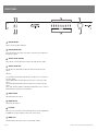
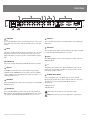
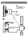
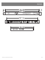
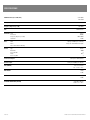
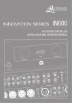
IN400
AV SWITCHING AMPLIFIER
INSTALLATION AND OPERATION MANUAL
IMPORTANT SAFETY INFORMATION
PRÉCAUTIONS DURANT UTILISATION
1.
Read these instructions.
1.
LISEZ ces instructions.
2.
Keep these instructions.
2.
Tenez ces instructions.
3.
Heed all warnings.
3.
Notez tous les avertissements.
4.
Follow all instructions.
4.
Suivez toutes les avertissements.
5.
Do not use this apparatus near water.
5.
N’utilisez pas ce produit près de l’eau (la piscine, la plage, le lac, etc.).
6.
Clean only with dry cloth.
6.
Nettoyez seulement avec une étoffe sèche.
7.
Do not block any ventilation openings. Install in accordance with the
manufacturer’s instructions.
7.
Ne bloquez aucuns troux de ventilation. Installez en accord avec
les instructions du manufacturier.
8.
Do not install near any heat sources such as radiators, heat registers,
stoves, or other apparatus (including amplifiers) that produce heat.
8.
N’installez près aucunes sources de chaleur comme radiateurs,
registres de chaleur, fours ou les autres équipements (y compris
amplificateurs) qui produisent la chaleur.
9.
Do not defeat the safety purpose of the polarized or grounding-type
plug. A polarized plug has two blades with one wider than the other.
A grounding type plug has two blades and a third grounding prong.
The wide blade or the third prong are provided for your safety. If the
provided plug does not fit into your outlet, consult an electrician for
replacement of the obsolete outlet.
9.
Ne défaites pas le but de sécurité de la fiche polarisée ou base-type.
Une fiche polarisée a deux tranchants avec un plus large que l’autre.
Une fiche de base type a deux a deux tranchants et une troisième
pointe de base, le tranchant large ou la troisième pointe est fourni
pour votre sécurité. Si la fiche donnée ne conforme pas votre prise
de contact, consultez un électricien pour remplacement de la prise
de contact obsolète.
10. Protect the power cord from being walked on or pinched particularly
at plugs, convenience receptacles, and the point where they exit from
the apparatus.
11. Only use attachments/accessories specified by the manufacturer.
12. Use only with the cart, stand, tripod, bracket, or table
specified by the manufacturer, or sold with the
apparatus. When a cart is used, use caution when
moving the cart/apparatus combination to avoid injury
from tip-over.
13. Unplug this apparatus during lightning storms or when
unused for long periods of time.
14. Refer all servicing to qualified service personnel. Servicing is required
when the apparatus has been damaged in any way, such as powersupply cord or plug is damaged, liquid has been spilled or objects have
fallen into the apparatus, the apparatus has been exposed to rain or
moisture, does not operate normally, or has been dropped.
15. This appliance shall not be exposed to dripping or splashing water and
that no object filled with liquid such as vases shall be placed on the
apparatus.
16. Plug this apparatus to the proper wall outlet and make the plug to be
disconnected readily operable.
17. Main plug is used as disconnected device and it should remain readily
operable during intended use. In order to disconnect the apparatus from
the mains completely, the mains plug should be disconnected from the
mains socket outlet completely.
10. Protegez le cordon de secteur contre être marchée dessus ou pincez
en particulier aux fiches, aux douilles de convenance, et au point où ils
sortent de l’appareil.
11. Seulement utilisez attachements/accessoires spécifiés par le
manufacturier.
12. Utilisez seulement avec un chariot, un stand, un
trépied, un support ou une table indiquée par le
manufacturier, ou vendue avec l’appareil. Quand un
chariot est utilisé, faites attention en déplaçant la
combinaison d’appareil/chariot pour éviter de se
déséquilibrer.
13. Arrachez la fiche du dispositif durant éclair et orage ou quand
pas utilisé pour longues périodes de temps.
14. Référez au personnel qualifié de service pour toutes réparations.
La réparation est donnée quand le système a été endommagé à
n’importe façon, par exemple un fil ou une fiche endommagé(e)
de la source d’alimentation. Avoir été exposé à pluie ou humidité,
n’opère pas normalement, ou avoir été tombé.
15. L’appareil ne doit pas être exposé aux écoulements ou aux
éclaboussures et aucun objet ne contenant de liquide, tel qu’un vase,
ne doit être placé sur l’objet.
16. Branchez l’appareil à une source appropriée et faire que la prise à
débrancher soit facilement accessible.
18. WARNING: To reduce the risk of fire or electric shock, do not expose this
apparatus to rain or moisture.
17. La prise du secteur ne doit pas être obstruée ou doit être facilement
accessible pendant son utilisation. Pour être complètement déconnecté
de l’alimentation d’entrée, la prise doit être débranchée du secteur.
19. An appliance with a protective earth terminal should be connected to a
mains outlet with a protective earth connection.
18. AVERTISSEMENT: Pour éviter le risque d’incendie ou de chocs
électriques, ne pas exposer cet appareil à la pluie ou à l’humidité.
19. Un appareil avec la borne de terre de protection doit être connecté au
secteur avec la connexiion de terre de protection.
INTRODUCTION AND CONTENTS
The Innovation series from AMAV is a huge step forward in the interfacing and
management of audio and visual sources. Integrating a host of smart, high end
features in a compact package that offers the end user extremely simple control
over their complex audio visual system. The Innovation series is as ground
breaking as it is simple to operate.
The IN400 is a compact AV switching amplifier with a host of extra features
available to the AV integrator. With 8 AV inputs as well as mix in, stereo line
output, 2 composite video outputs, VGA video output, 80 watt per channel
powered outputs, IR control, RS485 control and video away from audio split the
IN400 is perfect for boardroom, lecture theatre or training facility installations as
a stand alone control unit or as part of a larger system interfacing with a third
party control system.
INTRODUCTION
3
FRONT PANEL
4
REAR PANEL
5
SETUP
6
INSTALLATION
7
BLOCK DIAGRAM
8
DIMENSIONS
9
SPECIFICATIONS
10
AUS, EUR, USA
Copyright 21st Aug 2008
REV A 21st Aug 2008
REV B 9th Dec 2008
REV C 8th Apr 2010
REV D 7th June 2010
WARNING!
TO PREVENT FIRE OR SHOCK HAZARD, DO NOT USE THE PLUG WITH AN EXTENSION CORD, RECEPTACLE OR
OTHER OUTLET UNLESS THE BLADES CAN BE FULLY INSERTED TO PREVENT BLADE EXPOSURE.
TO REDUCE THE RISK OF FIRE OR ELECTRIC SHOCK, DO NOT EXPOSE THIS APPLIANCE TO RAIN OR MOISTURE.
TO PREVENT ELECTRICAL SHOCK, MATCH WIDE BLADE PLUG TO WIDE SLOT, FULLY INSERT.
CAUTION
RISK OF ELECTRIC SHOCK
DO NOT OPEN
The lightning flash with arrowhead symbol,
within an equilateral triangle, is intended
to alert the user to the presence of
uninsulated “dangerous voltage” within
the product’s enclosure that may be of
sufficient magnitude to constitute a risk
of electric shock to persons.
WARNING: TO REDUCE THE RISK
OF ELECTRIC SHOCK, DO NOT
REMOVE COVER (OR BACK).
NO USER SERVICEABLE PARTS INSIDE.
REFER SERVICING TO QUALIFIED
SERVICE PERSONNEL.
The exclamation point within an equilateral
triangle is intended to alert the user to
the presence of important operating and
maintenance (servicing) instructions in the
literature accompanying the appliance.
Rating plate and caution marking are marked on the back enclosure of the apparatus
IN400 INSTALLATION AND OPERATION MANUAL
PAGE 3
FRONT PANEL
6
8
4
5 7
3
2
1
1 MASTER VOLUME
This pot controls the audio output level.
2 MASTER VOLUME LEDS
These LED’s indicate the position of the volume control. They do not indicate the
strength of the signal.
3 SOURCE SELECT SWITCHES
These switches select the input that is routed to the audio and video outputs.
4 SOURCE SELECT LEDS
The LED above the switch indicates when the channel is being routed to the
outputs.
LED State
1. A solid LED means that both audio and video from that source is routed to the
respective outputs.
2. A long flasing LED means that audio from that source is routed to the audio
output.
3. A short flasing LED means that video from that source is routed to the video
output.
Source audio and video splitting is achievable through RS485. See the section on
Communications on page 6 for more information.
5 POWER SWITCH
This switch switches the unit on.
6 POWER ON LED
This indicates the unit is on.
7 IR SENSOR
This is the sensor used for IR control. A hand held remote control is supplied with
the IN400. Line of sight is required for the remote control to work.
8 COMMS LED
This LED indicates when data is sent or revceived via IR or RS485.
PAGE 4
IN400 INSTALLATION AND OPERATION MANUAL
REAR PANEL
4
11
1
2
3
5
6
10 9
1 AUDIO INPUT
Sources
These are the RCA unbalanced line level audio inputs for each of the 8 sources.
The top RCA connector is the left channel, bottom RCA connector is the right
channel.
7
8
7 VGA INPUT
These are high densisty 15pin D connector VGA inputs for the PC1/PC2/AUX3/
AUX4 sources.
8 VGA OUTPUT
2 MIX IN
This input is not switched but mixes with the selected audio source. The bass/
treble/volume controls do not affect this input. This feature can be used in
paging environments or emergency systems in conjuction with the L1 trigger
input.
3 AUDIO OUTPUT
These are the left (top) and right (bottom) RCA unbalanced line level outputs.
4 AMP OUT
The IN400 has a built in audio stereo power amplifier. The input signal is
parallelled from the AUDIO OUTPUT. The power amp is rated at 2 x 80W into
4 ohm, 2 x 50W into 8ohm. The minimum load is 4ohm. The outputs are on a
5.08mm pluggable connector.
5 VIDEO INPUT
These are RCA unbalanced 75ohm composite video inputs for the DVD1/DVD2/
AUX1/AUX2 sources.
6 VIDEO OUTPUT
These are the RCA unbalanced 75ohm composite video outputs. OUT1 and
OUT2 output the same signal but they are individually buffered. These outputs
only output the signal from DVD1/DVD2/AUX1/AUX2 sources if selected.
IN400 INSTALLATION AND OPERATION MANUAL
This is the high densisty 15pin D connector VGA output. This output only outputs
the signal from PC1/PC2/AUX3/AUX4 sources if selected.
9 RS485
This 5.08mm pluggable connector socket is provided for external control of the
IN400 using RS485.
10 L1
This input is used to mute the audio outputs. The MIX IN is not affected. This
feature can be used in paging environments or emergency systems. Short it to
the RS485 ground pin to activate it.
11 IEC MAINS INPUT SOCKET
This is a standard IEC 3 pin socket (IEC320-C14). It accepts a standard
IEC mains cable, provided. The fuse draw contains the mains fuse and a spare.
The mains fuse is a time lag (slow blow) HRC 20mm x 5mm fuse.
The ratings are:
230V Model T3.15A
120V Model T6.3A
Always replace the fuse with one of the same value and type.
Note: Always disconnect power to the amplifier before replacing fuses.
PAGE 5
SETUP
RS485 Settings
Word Structure
RS485 Setup
Baud Rate:
No. of Bits:
Stop Bit:
Parity Bit:
! - Start byte
XXX - 3 byte command
: - delimiter
XXX - 3 byte data
<CR> - carriage return
All bytes are ASCII
characters.
The IN400 data port is an RS485 serial data port. Twisted pair cabling should be used when connecting
RS485 devices, such as CAT3, CAT5, CAT5e or CAT6 UTP cabling. RS485 data networks should be wired
in a ‘daisy chain’ configuration with a maximum of 32 devices in the chain. The IN400 is not terminated
so may be inserted anywhere in the data network. If the IN400 is being used at the end of a chain,
a 120ohm (characteristic impedance of UTP) terminating resistor should be connected between
the + and - connections.
9600
8
1
None
The IN400 has built in failsafe bias circuitry so there are no need for external biasing resistors.
The maximum length of the chain is 500m.
Data Commands
COMMS
DESCRIPTION
!VER:???<CR>
Version request. Device replies with !VER=xyz where xyz is the version ID of the firmware.
!GMD:???<CR>
Global Mode request. Device replies with !GMD=00x, where x is 0 if global mode is not active and 1 if global mode is active.
!LOK:???<CR>
Panel Lock request. Device replies with !LOK=00x, where x is 0 if panel lock is not active and 1 if panel lock is active.
!PWR:???<CR>
Soft Power request. Device replies with !PWR=00x, where x is 0 if soft power state if off and 1 if soft power state is on.
!BAS:???<CR>
Bass request. Device replies with !BAS=0xy, where xy is the current setting of bass.
!TRE:???<CR>
Treble request. Device replies with !TRE=0xy, where xy is the current setting of treble.
!VOL:???<CR>
Volume request. Device replies with !VOL=xyz, where xyz is the current setting of volume.
!MUT:???<CR>
Mute request. Device replies with !MUT=0xy, where x represents the audio mute and y represents the video mute.
!SRS:???<CR>
Source request. Device replies with !SRS=0xy, where x represents the audio source and y represents the video source.
!GMD:000<CR>
Global Mode set. Global mode is deactivated. Device replies with !GMD=000 when done.
!GMD:001<CR>
Global Mode set. Global mode is activated. Device replies with !GMD=001 when done.
!LOK:000<CR>
Panel Lock set. Panel lock is deactivated. Device replies with !LOK=000 when done.
!LOK:001<CR>
Panel Lock set. Panel lock is activated. Device replies with !LOK=001 when done.
!PWR:000<CR>
Soft Power set. Device is put into soft power off. Device replies with !PWR=000 when done.
!PWR:001<CR>
Soft Power set. Device is put into soft power on. Device replies with !PWR=001 when done.
!MUT:0xy<CR>
Mute set. If x is 0, the audio is muted. If y is 0, the video is muted. If x is 1, the audio is unmuted. If y is 1, the video is unmuted. Device
replies with !MUT=0ab, where a represents the new audio mute state and b represents the new video mute state.
!SRS:0xy<CR>
Source Select set. The audio source is set to x. The video source is set to y. Device replies with !SRS=0ab, where a represents the new
audio source and b represents the new video source.
!VOL:xyz<CR>
Volume set. The volume is set to xyz. The device replies with !VOL=abc where abc is the new volume.
!VOL:+++<CR>
Volume increment. The volume is incremented by 1. The device replies with !VOL=abc where abc is the new volume.
!VOL:---<CR>
Volume decrement. The volume is decremented by 1. The device replies with !VOL=abc where abc is the new volume.
!BAS:0xy<CR>
Bass set. The bass is set to xy. The device replies with !BAS=0ab where ab is the new bass.
!BAS:+++<CR>
Bass increment. The bass is incremented by 1. The device replies with !BAS=0ab where ab is the new bass.
!BAS:---<CR>
Bass decrement. The bass is decremented by 1. The device replies with !BAS=0ab where ab is the new bass.
!TRE:0xy<CR>
Treble set. The treble is set to xy. The device replies with !TRE=0ab where ab is the new treble.
!TRE:+++<CR>
Treble increment. The treble is incremented by 1. The device replies with !TRE=0ab where ab is the new treble.
!TRE:---<CR>
Treble decrement. The treble is decremented by 1. The device replies with !TRE=0ab where ab is the new treble.
Global Mode
When the IN400 is in global mode, changes to the volume and tone affect all the sources.
When not in global mode, changes to the volume and tone affects the selected source.
PAGE 6
IN400 INSTALLATION AND OPERATION MANUAL
INSTALLATION
All installation work should be done with the power disconnected. The following inforamtion will help with installation. After installation is complete power up all the
sources before turning on the IN400.
POWER CONNECTION
OUTPUT CONNECTIONS (cont.)
Ensure the mains voltage supply matches the rear of the IN400 (+/- 10%)
Video
Video outputs are on either unbalanced RCA sockets (composite) or 15 pin high
density female connectors D-connectors (VGA). The maximum cable length for
composite video is typically less than 3m for shielded wire and 10m for coaxial
before signal degradation. This will depend on the cable quality.
Ensure that all system grounds (earth) are connected to a common point. Avoid
powering equipment within a system from multiple power sources that may be
separated by large distances. This will eliminate ground loops that are heard as
50/60Hz humming or buzzing in speakers and seen as moving or stationary bars
on video equipment.
INPUT CONNECTIONS
Audio
All the inputs are unbalanced RCA sockets. Unbalanced RCA wiring should be
keep as short as possible. Typically less than 3m.
Video
Video inputs are on either unbalanced RCA sockets (composite) or 15 pin high
density female connectors D-connectors (VGA). The maximum cable length for
composite video is typically less than 3m for shielded wire and 10m for coaxial
before signal degradation. This will depend on the cable quality.
OUTPUT CONNECTIONS
Audio
The line level outputs are unbalanced RCA sockets. Unbalanced RCA wiring should
be keep as short as possible. Typically less than 3m.
The amplifier outputs are 5.08mm pluggable connectors. Use the following table
for selecting a suitable guage wire for the cable you are running over a particular
distance. The table is for a 1dB drop in level which is generally considered
acceptable.
AWG10 AWG13 AWG14 AWG16 AWG17 AWG18 AWG20 AWG22 AWG24 AWG26
Speaker
16
279
125
100
75
51
38
26
17
11
6
8
139
62
50
37
26
19a
13
9
6
3
4
70
31
25
19
13
10
There are two composite outputs for running to 2 different monitors without the
need for an external distribution amplifier.
VGA pin out
1
Red out
2
Green out
3
Blue out
4
Monitor ID 2 in
5
Ground
6
Red return
7
Green return
8
Blue return
9
no pin
10 Sync return
11 Monitor ID 0 in
12 Monitor ID 1 in
13 Horizonal Sync out
14 Vertical Sync out
15 reserved (monitor ID 3)
Only pins 1,2,3,5,6,7,8,10,13,14 are used in the IN400.
RS485 CONNECTIONS
The RS485 data port is on a 5.08mm pluggable connectors. Twisted pair cabling
should be used When connecting RS485 devices, such as CAT3, CAT5, CAT5e
or CAT6 UTP cabling. RS485 data networks should be wired in a ‘daisy chain’
configuration with a maximum of 32 devices in the chain. The IN400 is not
terminated so may be inserted anywhere in the data network. If the IN400 is
being used at the end of a chain, a 120ohm (characteristic impedance of UTP)
terminating resistor should be connected between the + and - connections.
The maximum length of the chain is 500m.
Do not connect a total impedance of less than 4ohm per channel.
IN400 INSTALLATION AND OPERATION MANUAL
PAGE 7
BLOCK DIAGRAM
PAGE 8
IN400 INSTALLATION AND OPERATION MANUAL
DIMENSIONS
IN400 INSTALLATION AND OPERATION MANUAL
PAGE 9
SPECIFICATIONS
POWER OUTPUT (0.5%THD, 1kHz)
8ohm 50W,
4ohm 80W
THD (20-10kHz, 8ohm, -2dBr)
Better than 0.1%
Frequency Response(+/-3dB)
20-20kHz
Gain
24dB @ 8ohm
Line Audio THD
Noise Floor
Frequency Response(+/-3dB)
Headroom
Video
VGA
Video
Video follows Audio switching
Comms
Type
Baud Rate
No of Data Bit
Parity
No of Stop Bits
Power Consumption
Thermal output
SIZE (WXHXD)
<0.5%
-90dBu
20Hz-20kHz
+5dBu
High speed RGB+Sync switching
Composite 75ohm Buffered outputs
RS485
9600
8
None
1
1/8th power 150VA (0.65A)
1/8th power 100W (341.2Btu/hr)
482 x 44 x 325mm
19 ” x 1.75” x 12.8”
NET WEIGHT
7.0kg
15.4lb
SHIPPING WEIGHT
9.0kg
19.8lb
SHIPPING DIMENSIONS (WXHXD)
PAGE 10
520 x 90 x 420 mm
19.0” x 3.5” x 16.5”
IN400 INSTALLATION AND OPERATION MANUAL
NOTES
IN400 INSTALLATION AND OPERATION MANUAL
PAGE 11
AUSTRALIA AND NEW ZEALAND
www.australianmonitor.com.au
SYDNEY
MELBOURNE
ADELAIDE
AUCKLAND
(NSW SALES)
(VIC & TAS SALES)
(SA & NT SALES)
(NZ SALES)
1 Clyde Street
Silverwater
NSW 2128
Private Bag 149
Silverwater NSW 1811
Phone: (02) 9647 1411
Fax: (02) 9648 3698
Email:
[email protected]
22/277
Middleborough Road
Box Hill VIC 3128
PO Box 151 Blackburn
South VIC 3130
Phone: (03) 9890 7477
Fax: (03) 9890 7977
Email:
[email protected]
31 Walsh Street
Thebarton
SA 5031
PO Box 157
Hindmarsh SA 5007
Phone: (08) 8352 4444
Fax: (08) 8352 4488
Email:
[email protected]
9C Piermark Drive
Albany 0752
New Zealand
PO Box 300-512
Albany 0752
Phone: (09) 415 9426
Fax: (09) 415 9864
Email:
[email protected]
CANBERRA
BRISBANE
PERTH
(ACT SALES)
(QLD SALES)
(WA SALES)
1st Floor,
Campion Street
Deakin ACT 2600
PO Box 109
Deakin West ACT 2600
Phone: (02) 6260 4544
Fax: (02) 6260 4744
Email: gordon.anderson@
hillssvl.com.au
42 Commercial Road
Fortitude Valley
QLD 4006
PO Box 2578 Fortitude
Valley BC QLD 4006
Phone: (07) 3852 1312
Fax: (07) 3252 1237
Email:
[email protected]
3/11 Howe Street
Osborne Park WA 6017
PO Box 1281
Osborne Park BC
WA 6916
Phone: (08) 9204 0200
Fax: (08) 9244 3783
Email:
[email protected]
EUROPE / ASIA / MIDDLE EAST
www.australianmonitor.com.au
INTERNATIONAL SALES
1 Clyde Street Silverwater NSW 2128 Australia
Private Bag 149 Silverwater NSW 1811
Phone: + 61 2 9647 1411
Fax: + 61 2 9748 2537
Email: [email protected]