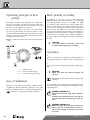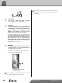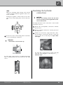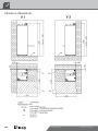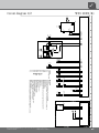
1
Operati ng Manual UK BRINE/WATER HEAT PUMPS Heat station brine WZS Series We reserve the right to modify technical specifications without prior notice. UK830501/200520 © Alpha-InnoTec GmbH Please read first Symbols This operating manual provides important information on the handling of the unit. It is an integral part of the product and must be stored so that it is accessible in the immediate vicinity of the unit. It must remain available throughout the entire service life of the unit. It must be handed over to subsequent owners or operators of the unit. The following symbols are used in the operating manual. They have the following meaning: Information for operators. Information or instructions for qualified technicians. Read the operating manual before working on or operating the unit. This applies in particular to the chapter on safety. Always follow all instructions completely and without restrictions. DANGER! Indicates a direct impending danger resulting in severe injuries or death. It is possible that this operating manual may contain instructions that seem incomprehensible or unclear. In case of questions or uncertainty, contact the factory customer service department or the manufacturer’s local service partner. WARNING! Indicates a possibly dangerous situation that could result in severe injuries or death. Since this operating manual was written for several different models of the unit, always comply with the parameters for the respective model. CAUTION! This operating manual is intended only for persons assigned to work on or operate the unit. Treat all constituent parts confidentially. The information contained herein is protected by copyright. No part of this operating manual may be reproduced, transmitted, copied, stored in electronic data systems or translated into another language, either wholly or in part, without the express written permission of the manufacturer. Indicates a possibly dangerous situation that could result in medium or light injuries. CAUTION. Indicates a possibly dangerous situation, which could result in property damage. NOTICE. Emphasized information. € ENERGY SAVING TIP Indicates suggestions that help to save energy, raw materials and costs. Reference to other sections of the operating manual. Reference to other instructions of the manufacturer. 2 We reserve the right to modify technical specifications without prior notice. UK830501/200520 © Alpha-InnoTec GmbH Contents INFORMATION FOR OPERATORS AND QUALIFIED SPECIALISTS PLEASE READ FIRST ..................................................................2 SYMBOLS .....................................................................................2 INTENDED USE..........................................................................4 EXCLUSION OF LIABILITY......................................................4 EC CONFORMITY .....................................................................4 SAFETY .........................................................................................4 CUSTOMER SERVICE ................................................................5 Bleeding the heat source for a unit without cooling function .............................................24 Bleeding the heat source for a unit with cooling function ...................................................24 INSULATING THE HYDRAULIC CONNECTIONS ..........25 OVERFLOW VALVE ..................................................................26 Inspecting and setting up the overflow valve .................26 INSTALLATION OF THE CONTROL ELEMENT ...............26 INSTALLATION AND REMOVAL OF THE SCREEN .........28 WARRANTY / GUARANTEE ...................................................5 INSTALLATION OF THE ROOM THERMOSTAT FOR THE COOLING FUNCTION..................................29 DISPOSAL ....................................................................................5 HOT-WATER TANK.................................................................29 INFORMATION FOR OPERATORS OPERATING PRINCIPLE OF HEAT PUMPS ..........................6 AREA OF UTILIZATION ...........................................................6 HEAT QUANTITY RECORDING ............................................6 OPERATION................................................................................6 COOLING FUNCTION ............................................................7 CARE OF THE UNIT..................................................................8 MAINTENANCE OF THE UNIT ..............................................8 Cleaning and rinsing of unit components..........................9 MALFUNCTIONS .......................................................................9 INSTRUCTIONS FOR QUALIFIED TECHNICIANS SCOPE OF DELIVERY ......................................................9 INSTALLATION AND ASSEMBLY .........................................10 Installation area...................................................................10 Transport to installation location ....................................10 Installation............................................................................ 11 Installation of the module box..........................................12 Installation of the hydraulic connections ........................ 13 Opening the angle ball valves on the module box.........18 Safety component ...............................................................18 Expansion vessels................................................................18 ELECTRICAL CONNECTIONS .............................................18 RINSING AND FILLING THE UNIT .....................................21 Cleaning and rinsing of unit components........................21 Rinsing and filling the heat source ...................................21 Rinsing and filling the hot water and heating water circuits ..................................................22 RINSING, FILLING AND BLEEDING THE HOT WATER TANK ...........................................23 COMMISSIONING ...................................................................30 Safety temperature limiter ................................................30 DISMANTLING .........................................................................31 TECHNICAL DATA / SCOPE OF DELIVERY WZS 60H(/K) – WZS 100H(/K).......................................32 PERFORMANCE CURVES Heating capacity/COP / Power consumption / Free compression WZS 60H(/K) ......................................................................34 WZS 80H(/K) ......................................................................35 WZS 100H(/K) ....................................................................36 DIMENSIONAL DRAWINGS AND CLEARANCE DIMENSIONS Dimensional drawings ........................................................37 Clearance dimensions ........................................................38 TERMINAL DIAGRAM.............................................................39 CIRCUIT DIAGRAMS ............................................................. 40 WZS 60H(/K) – WZS 80H(/K)........................................ 40 WZS 100H(/K) ....................................................................42 APPENDIX EC DECLARATION OF CONFORMITY ............................. 44 GENERAL CHECKLIST ...........................................................45 COMPLETION REPORT FOR HEAT PUMP SYSTEMS ......47 CUSTOMER SERV R ICE Addresses in the event of a service call ..........................50 BLEEDING..................................................................................23 Bleeding the circulating pump of the heating circuit ....23 Bleeding the module box ...................................................23 Bleeding the circulating pump of the heat source .........24 We reserve the right to modify technical specifications without prior notice. UK830501/200520 © Alpha-InnoTec GmbH 3 Intended use EC conformity The unit bears the CE mark of conformity. means: EC declaration of conformity r for heating. r for heating hot water. r for cooling. (Availability of the cooling function depends on the model). “Cooling function” section. The unit may be operated only within its technical parameters. Overview “Technical data/scope of delivery”. NOTICE. Notify the responsible power supply company of the use of a heat pump or heat pump system. Safety The unit is operational safe when used for the intended purpose. The construction and design of the unit conform to the state of the art, all relevant DIN/VDE regulations and all relevant safety regulations. Every person who performs work on the unit must have read and understood the operating manual prior to starting any work. This also applies if the respective person has already worked with such a unit or a similar unit or has been trained by the manufacturer. Every person who performs work on the unit must comply with the applicable accident prevention and safety regulations. This applies in particular to the wearing of personal safety gear. DANGER! Exclusion of liability The manufacturer will not be liable for damage resulting from unauthorized use of the unit. The manufacturer’s liability will also be voided in the following cases: r if work is performed on the unit and its components in a manner that does not comply with the terms of this operating manual; Unit operates under high electric voltage! DANGER! Danger of fatal injury due to electric current! Electrical connections may be installed only by qualified electricians. Before opening the unit, disconnect the system from the power supply and secure it from being switched back on! rif work is performed on the unit and its components in an improper manner; r if work is performed on the unit that is not described in this operating manual, and this work was not expressly approved in writing by the manufacturer; r if the unit or components in the unit are modified, redesigned or removed without the express written permission of the manufacturer. DANGER! Only qualified technicians (trained heating, cooling, refrigerant and electrical technicians) may perform work on the unit and its components. WARNING! Observe safety labels on and in the unit. DANGER! Unit contains refrigerants! 4 We reserve the right to modify technical specifications without prior notice. UK830501/200520 © Alpha-InnoTec GmbH WARNING! Leaking refrigerant could result in personal injury or material damage. – Shut down unit. – Ventilate installation location. – Notify the manufacturer’s authorized service center. CAUTION. For safety reasons: Never disconnect the unit from the power supply, unless the unit is being opened. Customer service For technical assistance, please contact your qualified technician or the manufacturer’s local service partner. Overview “Customer service”. Warranty / Guarantee For warranty and guarantee conditions, please refer to the purchase documents. NOTICE. Please contact your dealer concerning warranties and guarantees. Disposal When decommissioning the unit, always comply with applicable laws, directives and standards for the recovery, recycling and disposal of materials and components of cooling units. “Dismantling”. We reserve the right to modify technical specifications without prior notice. UK830501/200520 © Alpha-InnoTec GmbH 5 Operating principle of heat pumps Heat pumps operate on the principle of a refrigerator: the same technology, only with the opposite effect. The refrigerator extracts heat from foods, which is released into the room through fins on the back. The heat pump extracts heat from our environment: air, earth or ground water. The extracted heat is conditioned in the unit and supplied to the heating water. Even when it is extremely cold outside, the heat pump draws enough heat to heat a house. Example: drawing of a brine/water heat pump with floor heating: Heat quantity recording In addition to the proof of the unit’s efficiency, EEWaermeGalso meets the demand for a heat quantity recording (hereafter refered to as HQR). The HQR is mandatory with air/water heat pumps. With brine/ water and water/water heat pumps, a HQR may only be set up when a forward flow temperature of ≥ 35 °C has been reached. The HQR must record the total warm energy release (heating and hot water) in the building. In heat pumps with heat quantity recording, the analysis is conducted by the regulator. The regulator displays the thermal energy that is exchanged from the heating system in kWh. NOTICE. Variant models are available, either with or without heat quantity recording. Operation Your decision to purchase a heat pump or a heat pump Y system is a long-term contribution to protecting the environment through low emissions and reduced primary energy use. You can operate and control the heat pump system with Y the control element of the heating and heat pump regulator. 4 ⁄4 = usable energy ca. 3 ⁄4 = environmental energy ca. 1 ⁄4 = external electrical energy NOTICE. Make sure that the control settings are correct. Operating manual of the heating and heat pump regulator. Area of utilization Taking into consideration the ambient conditions, limits of application and the applicable regulations, every heat pump can be utilized in new or existing heating systems. Overview “Technical data/scope of delivery”. To ensure that your heat pump or heat pump system operates efficiently and ecologically, the following are especially important: € ENERGY SAVING TIP Avoid unnecessarily high flow temperatures. A lower flow temperature on the hot water side increases the efficiency of the system. € ENERGY SAVING TIP When letting in fresh air, do not leave windows open for an extended period in order to save energy and reduce your heating costs. 6 We reserve the right to modify technical specifications without prior notice. UK830501/200520 © Alpha-InnoTec GmbH Cooling function The cooling function is available only for heat pumps with the model designator K. THE ROOM THERMOSTAT FOR THE COOLING FUNCTION The room thermostat is used to switch the cooling function on and off: It is not possible to retrofit heat pumps for cooling without this designator. For the model designator, please refer to the purchase documents. It is also on the rating plate attached to the outside of the unit. I Cooling function on Cooling function off UTILIZATION OF THE COOLING FUNCTION The cooling function is based on the principle of passive cooling. An existing low temperature level is mixed to a temperature above the dew point and transferred to the heating medium by means of a heat exchanger. The heat pump remains switched off during cooling; only the circulating pumps for the heating circuit and the heat source are in operation. The cooling power depends on the heat source temperature, which varies seasonally. For example, if the ground stored more heat toward the end of the summer, the cooling power of a brine/water pump is reduced. The effectiveness of passive cooling is generally not comparable to that of an air conditioning system. NOTICE. The use of the passive cooling function requires floor or wall heating. The heating and heat pump regulation program activates the cooling function only if the following conditions are fulfilled: r Heat pump model must have integrated cooling function. r Room thermostat for the cooling function must be switched on. r Temperature of the heat source must be ≥ +5 °C. r Heat pump must not currently be occupied with “heating” or “water heating”. If the heat pump regulation program sends the command “water heating” to the heat pump, the cooling function of the heat pump automatically stops as long as the water is heating. r The “Automatic” setting must be selected on the control element under “Operating mode: cooling”. r The outdoor temperature release set on the control element must be exceeded. Operating manual of the heating and heat pump regulator. The cooling function can be used in two variants: Variant 1: Manual switching from heating to cooling operation (and vice versa). This variant operates at a pre-set forward flow temperature. Operating manual of the heating and heat pump regulator. We reserve the right to modify technical specifications without prior notice. UK830501/200520 © Alpha-InnoTec GmbH 7 Variant 2: Automatic switching from heating to cooling operation (and vice versa). This variant can operate using a cooling curve. NOTICE. Variant 2 is possible only if a Comfort board (available at extra charge) is built into the heating and heat pump regulator. Comfort board operating manual. Care of the unit The outer surfaces of the unit can be cleaned with a damp cloth and household cleaning products. Do not use cleaning or care products that contain abrasives, acids and/or chlorine. Such products would destroy the surfaces and could also damage the technical components of the unit. Maintenance of the unit The cooling circuit of the heat pump requires no regular maintenance. According to EU regulation (EC) 842/2006 of May 17, 2006, leak inspections and maintenance of a log book are required by law for certain heat pumps! The criteria for conducting leak inspections and maintaining a log book are based on the hermetic impermeability of the cooling circuit and the refrigerant capacity of the heat pump! No log book is required for heat pumps with a refrigerant capacity of < 3kg. With all other heat pumps, the log book is included with all other delivered materials. Log book for heat pumps, Section “Information on use of the log book”. The components of the heating circuit and the heat source (valves, expansion vessels, circulating pumps, filters, dirt traps) should be inspected as well as cleaned as needed - at the very least annually - by a qualified heating or cooling system technician. The hot water tank should be cleaned once each year. by a qualified technician. To do this, first empty the hot water tank. Then remove the Styrofoam guard through the service hole of the hot water tank. Screw off the flange cover of the service hole. 1 Hot water tank service hole (under Styrofoam cover) 2 Hot water tank emptying valve Check the safety valve (provided by customer) for the hot water tank at regular intervals. Since an external current anode is built in, the anode requires no maintenance. It is a good idea to have a maintenance contract with a heating installation company. The company will conduct all required maintenance at regular intervals. 8 We reserve the right to modify technical specifications without prior notice. UK830501/200520 © Alpha-InnoTec GmbH CLEANING AND RINSING OF UNIT COMPONENTS CAUTION! Scope of delivery Example of scope of delivery: Unit components may be cleaned and rinsed only by customer service personnel authorized by the manufacturer. Use only liquids recommended by the manufacturer. Rinsing of the liquefier with chemical cleaning agents must be followed by neutralization of residue and intensive rinsing with water. Always observe the technical data of the manufacturer of the heat exchanger. Malfunctions In the event of a malfunction, you can detect the cause of the malfunction via the diagnostic program of the heat pump and heating regulator. Operating manual of the heat pump and heating regulator. DANGER! Service and repair work on the components of the unit may be performed only by customer service personnel authorized by the manufacturer. Overview “Customer service”. Note that no fault is displayed if the safety temperature limiter has triggered at the heating element (depends on device). Commissioning”, “Safety temperature limiter” section. We reserve the right to modify technical specifications without prior notice. UK830501/200520 © Alpha-InnoTec GmbH 1 Compact unit with integrated hot water tank, electric heating element, integrated circulating pump heating circuit and sensors 2 Screen 3 Vibration decouplers for heat source connection 4 Control element of the heating and heat pump regulator 5 Safety component for heating circuit 6 Package with 4 feet, 1 outdoor sensor, 1 insulating set, 2 ball valves (model with designator K: 1 ball valve), 8 seals, 1 service hose, 1 cap valve, 1 mount for expansion vessel of heating circuit, (model with cooling function: room thermostat) 7 Expansion vessel of heating circuit, 25 l 8 Expansion vessel of heat source, 12 l 9 Connection assembly for heat source 10 Module box with integrated circulating pump of heat source 9 Proceed as follows: Inspect delivery for outwardly visible signs of damage… Check to make sure that delivery is complete. Any defects or incorrect deliveries must be claimed immediately. NOTICE. Note the model. Overview “Technical data/scope of delivery” or rating plate on unit. TRANSPORT TO INSTALLATION LOCATION To avoid damage during transport, you should transport the unit to the final installation location (secured on a wooden pallet) using a lifting truck. If it is not possible to transport the unit to the final installation location using a lifting truck, you can also transport the unit using a hand truck. DANGER! Several people are required to transport the unit. Do not underestimate the weight of the units. Overview “Technical data/scope of delivery”, “General unit data” section. Installation and assembly CAUTION! Wear safety gloves. Observe the following when performing all work: NOTICE. Always comply with applicable accident prevention regulations, statutory regulations, ordinances and directives. WARNING! The heat pump or heat pump system may be installed and assembled only by a qualified technician! NOTICE. Observe the sound levels of the respective model. DANGER! Unit is not fastened to the wooden pallet. The unit can tip when being lifted down and during transport with a hand truck. This can result in personal injury and damage to the unit. – T Take suitable precautionary measures to eliminate the danger of tipping. Proceed as follows if transport with a lifting truck is not possible: Remove packaging and transport material. Remove extra box and module box from the wooden pallet and bring to installation location… Use straps to lift and carry the module box… Overview “Technical data/scope of delivery”, “Sound” section. INSTALLATION AREA CAUTION. Install the unit only indoors. The installation area must be frost-free and dry. It must meet the requirements of DIN EN 378. It must also fulfill applicable local regulations. 10 We reserve the right to modify technical specifications without prior notice. UK830501/200520 © Alpha-InnoTec GmbH CAUTION. CAUTION. Do not tilt the module box more than a maximum of 45° (in any direction). Do not damage the hydraulic connections under any circumstances. CAUTION. Never use components, pipes of the cooling circuit or hydraulic connections on the module box for transport purposes. – Push hand truck only beneath back of unit for transport. NOTICE: Without the module box, the unit can be transported horizontally. CAUTION. Do not damage the hydraulic connections under any circumstances. Dispose of angle bracket, transport and packaging material properly and in accordance with ecological principles. We recommend removing the front panel to reduce the weight of the unit for further transport… 1 Recessed grips 2 Carrying strap Loosen quick-release screws for the front panel. Turn counter-clockwise 90°… CAUTION. Never use components and hydraulic connections on the unit for purposes of transport. Lift front panel and set aside in a safe place… DANGER! The carrying strap attached to the back of the unit is an aid for tipping the unit onto a hand truck! Always secure the unit on the hand truck with a tension belt! The carrying strap can also be used as a transport aid so that the unit without the module box can be carried by two persons (see illustration)! Do not lift or transport the unit using only the strap! – The strap could break! – Persons could be injured! – Persons beneath the load could be fatally injured! – The unit and other objects could be damaged! Transport unit to installation location using a hand truck or have two persons carry it… We reserve the right to modify technical specifications without prior notice. UK830501/200520 © Alpha-InnoTec GmbH INSTALLATION DANGER! Several people are required to install the unit. Do not underestimate the weight of the unit. NOTICE. The heat source can be connected either on the left or right side of the unit. Maintain the required clearance between the connection side and the wall. “Installation of the hydraulic connections”, “Connection of module box to the heat source” section. CAUTION. Always comply with required clearance dimensions. “Dimensional drawings” and “Clearance dimensions” overviews. 11 Proceed as follows at the installation location: CAUTION. Set unit on a solid and level, preferably sound-insulated surface. Mount feet… CAUTION. Place unit at final installation location. Compensate for minor unevenness using the four adjusting screws. Then tighten the lock nuts. INSTALLATION OF THE MODULE BOX The entire cooling circuit of the heat station is contained in the module box. Moving the unit without the feet mounted can damage the floor. CAUTION. Mount the feet before installing the module box in the unit. Do not tilt the module box more than a maximum of 45° (in any direction). Proceed as follows to mount the feet on the unit: Place module box in front of the unit… r Tip the unit slowly and carefully to one side… Secure unit in raised position so that it cannot accidentally tip back into the original position… CAUTION! Hands and fingers could be crushed during the following tasks! r Mount one foot each on the front and back of the unit… 1 2 3 4 Unit Plug for electrical connection Front edge of bottom of unit Module box Use straps to lift module box and initially place in unit so that the rubber feet of the module box that are facing the unit come to rest on the centering plate behind the front edger of the bottom of the unit… 1 Foot 2 Lock nut 3 Adjusting screw r Slowly and carefully tip the unit back into the original position… Push module box into the unit until the front rubber foot of the module box contacts the front edge of the bottom of the unit and has to be lifted over it… When pushing in the box, make sure that the plugs for the electrical connection are not pinched and damaged. r Repeat procedure on the other side of the unit… 12 We reserve the right to modify technical specifications without prior notice. UK830501/200520 © Alpha-InnoTec GmbH WZS 80… and WZS 100…: Raise module box, push it further into the unit and lower the box as soon as the rubber feet contact the corresponding stops of the centering plate… Set the front left rubber foot of the module box between the guide elements… The module box is positioned correctly in the unit when the rubber feed are placed as shown in the following sketch: WZS 60…: 1 Stops on centering plate 2 Rear rubber feet of module box 3 Centering plate for module box on bottom of unit 4 Front rubber feet of module box 5 Guide element CAUTION. Once the module box has been placed in the unit, it can no longer be transported. INSTALLATION OF THE HYDRAULIC CONNECTIONS CAUTION. The heat source system must be designed according to the specifications of the heat pump guide. 1 Stops on centering plate 2 Rear rubber feet of module box 3 Centering plate for module box on bottom of unit 4 Front rubber foot of module box 5 Guide element Heat pump guide and “Hydraulic connection” instructions. NOTICE. Check to make sure that the diameters and lengths of the pipes for the heating circuit and the heat source are sufficiently dimensioned. The free compression of the circulating pumps must be able to deliver at least the minimum flow rate required for your model. Overview “Technical data/scope of delivery”, “Heat source” and “Heating circuit” sections. We reserve the right to modify technical specifications without prior notice. UK830501/200520 © Alpha-InnoTec GmbH 13 DANGER! CONNECTIONS ON THE MODULE BOX Danger of fatal injury due to electric current! Before opening the unit, disconnect the system from the power supply and secure it from being switched back on! Proceed as follows: Install shut-off devices at the heating circuit… Install shut-off devices at the heat source… NOTICE. During installation of the shut-off devices, the evaporator and liquefier of the heat pump can be rinsed, if necessary. CAUTION! The condenser may be rinsed only by customer service personnel authorized by the manufacturer. CAUTION. During connection of components, secure connections on the module box and on the compact unit against twisting in order to prevent damage to the copper pipes in the inside of the module box and the compact unit. 1 2 3 4 Heat source inflow Heat source outflow Electric/sensor lines Heating circuit outflow (forward flow) 5 Heating circuit inflow (return flow) CONNECTING THE MODULE BOX TO THE HEATING CIRCUIT The vibration decouplers for the connection of the heating circuit to the module box are pre-mounted in the unit. They are located to the right of the module box after it has been inserted. Proceed as follows: Place a bleeder at the highest point of the heat source in the heat source outflow… Remove two seals from the extra box and place them in the angle ball valves… If necessary, place a bleeder at the highest point of the heat source in the heat source inflow… Screw angle ball valves of the vibration decouplers to the heating circuit connections… Place a bleeder at the highest point of the heating circuit in the heating circuit outflow (forward flow)… If necessary, place a bleeder at the highest point of the heating circuit in the heating circuit inflow (return flow)… We recommend installing a contamination filter (screen size 0.9 mm) on the heat source inflow connection… 14 Heating circuit outflow (forward flow) connection We reserve the right to modify technical specifications without prior notice. UK830501/200520 © Alpha-InnoTec GmbH Heating circuit inflow (return flow) connection for models without cooling function. 1 Connection on left side of unit 2 Connection on right side of unit Proceed as follows: Cut out round plates on the desired connection side… Heating circuit inflow (return flow) connection for models with cooling function. NOTICE. Always note which is the inflow (return flow) and outflow (forward flow) of the heating circuit. They are marked with colors, as are the vibration decouplers: red = hot water outflow (forward flow) blue = hot water inflow (return flow) CONNECTING THE MODULE BOX TO THE HEAT SOURCE Make sure that no metal burrs remain. Cut foam with a knife… Insert included plastic rosettes in the holes… Vibration decouplers are included for the connection to the pipes of the heat source. They must be installed in order to prevent damage from vibrations to the pipes. The pipes of the heat source can be connected either on the right or left side of the unit. We reserve the right to modify technical specifications without prior notice. UK830501/200520 © Alpha-InnoTec GmbH 15 Insert vibration decouplers in unit from outside and guide them inside the unit to the connections on the module box. CAUTION. When tightening the connections on the module box, always secure connections against twisting. CONNECTION OF THE VIBRATION DECOUPLERS ON A UNIT WITH COOLING FUNCTION Proceed as follows: Arrange vibration decouplers in a quarter circle in the unit… CONNECTION OF THE VIBRATION DECOUPLERS ON A UNIT WITHOUT COOLING FUNCTION Example of hose installation for connection on right side of unit (top view): Proceed as follows: Arrange vibration decouplers in a quarter circle in the unit to the connections on the module box… Example of hose installation for connection on right side of unit (top view): 1 Heat source inflow 2 Heat source outflow 3 Connecting pipe to and from cooling function for heat source inflow Example of hose installation for connection on left side of unit (top view): 1 Heat source inflow 2 Heat source outflow Example of hose installation for connection on left side of unit (top view): 1 Heat source inflow 2 Heat source outflow 3 Connecting pipe to and from cooling function for heat source inflow, pre-mounted in unit 1 Heat source inflow 2 Heat source outflow Screw included angle ball valves to vibration decouplers. Use seals from the extra box… Screw angle ball valves to the connections provided on the module box. Use seals from the extra box… 16 We reserve the right to modify technical specifications without prior notice. UK830501/200520 © Alpha-InnoTec GmbH CONNECTING THE COMPACT UNIT TO THE HEATING CIRCUIT The connections for the pipes of the heating circuit and the hot water supply are located on the top of the unit. 1 Connection of heat source inflow to cooling function (not insulated at time of delivery) 2 Connection of heat source inflow from cooling function to module box (not insulated at time of delivery) Screw vibration decoupler (with elbow) of heat source inflow to provided connecting pipe. Use seals from the extra box… 1 Vibration decoupler without elbow 2 Vibration decoupler with elbow Screw included angle ball valve to vibration decoupler (without elbow) of heat source outflow. Use seals from the extra box… Screw angle ball valve to the connection for the heat source outflow on the module box. Use seals from the extra box. 1 Heating circuit inflow (return flow) 2 Connection for heating circuit safety component 3 External current anode (under plastic cap) 4 Hot water connection, warm 5 Hot water connection, cold 6 Heating circuit outflow (forward flow) Proceed as follows: Bleeding valves have to be installed above the heat station for connection of the heating circuit and the hot water supply… Connect hot water tank according to DIN 1988 and DIN 4753, Part 1 (or the local applicable standards and directives). CAUTION. When tightening the connections on the module box and the connecting pipe, always secure connections against twisting. We reserve the right to modify technical specifications without prior notice. UK830501/200520 © Alpha-InnoTec GmbH CAUTION. Do not exceed the operating pressures specified on the rating plate. Install a pressure reducer, if necessary. 17 OPENING THE ANGLE BALL VALVES ON THE MODULE BOX Open all angle ball valves on the module box by turning them 90° counter-clockwise. Electrical connections Observe the following when performing all work: DANGER! Danger of fatal injury due to electric current! Electrical connections may be installed only by qualified electricians. Before opening the unit, disconnect the system from the power supply and secure it from being switched back on! DANGER! Observe the relevant EN, VDE and/or applicable local safety regulations during the installation and during all electrical work. SAFETY COMPONENT The safety component for the heating circuit is in the extra box. Proceed as follows: Mount the safety component on the connection provided on the top of the unit.… The safety drain of the safety valve must lead into the drain via a funnel siphon in accordance with the applicable standards and regulations. Comply with technical connection requirements of the responsible power supply company (if required by the latter)! NOTICE. All live wires must be stripped before they are installed in the cable duct of the switch cabinets! Proceed as follows: Remove front panel of unit, if necessary… EXPANSION VESSELS The expansion vessel of the heat source is included in delivery and must be installed with the connection assembly. Transport to installation location, . Obtain overview of the interior of the unit… The expansion vessel for the heating circuit, the corresponding cap valve and the wall mount are included in the scope of delivery. They must be integrated in the heating circuit on-site in compliance with the applicable standards and directives. We recommend installing a suitable expansion vessel (not included in delivery) in the hot water circuit. This equalizes pressure fluctuations or water shocks in the cold water network and prevents unnecessary loss of water. 1 Ducts for electric/sensor cables with strain relief screws 2 Electrical switch cabinet 3 Intermediate floor of unit 18 We reserve the right to modify technical specifications without prior notice. UK830501/200520 © Alpha-InnoTec GmbH Connect connecting plug of module box… CAUTION. Insert all three connecting plugs of the module box in the plug-in connections on the bottom of the intermediate floor of the unit. Watch out for retaining nose. Plugs must be mounted for easy movement. CAUTION. Make sure to equip the power supply of the heat pump with a 3-pole automatic cut-out with at least 3 mm contact gap. Note the level of the release current. Overview “Technical data/scope of delivery”, “Electric” section. Open electrical switch cabinet of unit… To do this, only loosen the two upper screws of the cover plate. Remove the remaining screws. Now the cover plate can be removed… Insert load lines and external control and sensor wires in unit through holes at top for electric/sensor wires. Guide wires via the cable duct to the terminals. Tighten strain relief screws… Install electrical connections according to the terminal diagram and the circuit diagrams… “Terminal diagram” and “Circuit diagrams”. DANGER! Install electric connections only according to the terminal diagram and the circuit diagrams that apply to your model. 1 Connection for control unit 2 Connection for output compressor 3PE 3 Connection for additional heating 3NPE 4 N/PE 5 Only for units with cooling function: 3 additional terminals for room thermostat and dew point sensor 6 Contactor for heating element CAUTION. Ensure clockwise rotary field of the load power supply (compressor). – An incorrect rotary field of the compressor during operation can cause serious, irreparable damage to the compressor. We reserve the right to modify technical specifications without prior notice. UK830501/200520 © Alpha-InnoTec GmbH 19 Close the front panel of the unit if no further installation work inside the unit is to be performed immediately. CAUTION. The sensor cable for heat quantity recording may not be shortened! NOTICE. The control element of the heat and heat pump regulator can be a connection with a computer or network using an network cable designed for such pruposes, thus allowing the heating and heat pump regulator to be controlled remotely. If such a connection is desired, install a screened network cable (category 6, with RJ-45 plug) through the unit when installing the connections and run it through the front facade of the unit, parallel to the already-present heating and heat pump regulator control cable. NOTICE. Electric heating element is connected for 6 kW at factory. It can be connected for 2 or 4 kW on the contactor. For further information, see the adhesive label on the electric heating element. 1 Adhesive label on electric heating element After completion of all electrical installation work, close the switch cabinet inside the unit… 20 We reserve the right to modify technical specifications without prior notice. UK830501/200520 © Alpha-InnoTec GmbH Rinsing and filling the unit DANGER! Danger of fatal injury due to electric current! The electric switch cabinet inside the unit must be closed with the cabinet’s cover! 6 7 8 9 10 11 Overflow valve Electric heating element Rinsing ball valve Electrical switch cabinet Sensor for hot water tank Hot water tank service hole (under Styrofoam cover) 12 Hot water tank emptying valve Proceed as follows: Open unit if this has not already been done… Transport to installation location, . Obtain overview of the interior of the unit. DANGER! The electric switch cabinet inside the unit must be closed with the cabinet’s cover! CLEANING AND RINSING OF UNIT COMPONENTS CAUTION! Unit components may be cleaned and rinsed only by customer service personnel authorized by the manufacturer. Use only liquids recommended by the manufacturer. Rinsing of the liquefier with chemical cleaning agents must be followed by neutralization of residue and intensive rinsing with water. Always observe the technical data of the manufacturer of the heat exchanger. RINSING AND FILLING THE HEAT SOURCE Contamination and deposits in the heat source can cause malfunctions. Proceed as follows: Rinse heat source system thoroughly… Thoroughly mix the anti-freeze agent, available as an accessory, with water at the required ratio. Add only anti-freeze mixed with water to the heat source… Check concentration of anti-freeze in the mixture… CAUTION. 1 3-way switching valve for heating circuit/hot water 2 Circulating pump for heating circuit/hot water 3 Pump ball valves 4 Hot-water tank 5 Reset knob of electric heating element We reserve the right to modify technical specifications without prior notice. UK830501/200520 © Alpha-InnoTec GmbH The concentration of anti-freeze in the water must be at the level specified for your model. Overview “Technical data/scope of delivery”, “Heat source” section. Fill heat source with anti-freeze mixture. 21 RINSING AND FILLING THE HOT WATER AND HEATING WATER CIRCUITS Use the rinsing ball valves for rinsing and filling. Turn spindle 180° and rinse hot water circuit ca. 1 minute… Turn spindle 180° back to starting position (rounded side of spindle points to B)… Picture shows operating condition at time of delivery. Contamination and deposits in the heating circuit can cause malfunctions. CAUTION. Before rinsing and filling the device, the drain pipe of the safety valve must be connected.Do not exceed the response pressure of the safety valve. Rinse heating circuit! If necessary, heating and hot water circuit can be rinsed at the same time! To do so, turn spindle 30°… After completion of the rinsing and filling procedure, move spindle to starting position and mount the motor of the 3-way valve… NOTICE To ensure a good seat of the motor on the T valve, make sure that the U-bolt with the reduction is not pushed past the lug, because then the motor will not be held securely on the valve! Proceed as follows: Close rinsing ball valve 3… In order to be supported securely, the U-bolt must bear with both ends against the lug: Connect hose for water outlet to rinsing ball valve 1 and lead to a drain… Open rinsing ball valve 1… Connect hose for water inlet to rinsing ball valve 2… Open rinsing ball valve 2… Remove the motor of the 3-way valve. To do so, remove the U-bolt on the motor base and carefully pull the motor upward… Move rinsing ball valves to starting position. 22 We reserve the right to modify technical specifications without prior notice. UK830501/200520 © Alpha-InnoTec GmbH RINSING, FILLING AND BLEEDING THE HOT WATER TANK ION! The electrical conductivity of the hot water outflow must be > 100 μS/cm and must be comparable to water that is suitable for drinking. CAUTION. Before rinsing and filling the hot water tank, the drain pipe of the safety valve must be connected. Do not exceed the response pressure of the safety valve. Bleeding The unit is bled automatically when the bleeder (black cap) of the safety component of the heating circuit is open. If the heating circuit is filled or emptied, the bleeding valve of the safety component opens. BLEEDING THE CIRCULATING PUMP OF THE HEATING CIRCUIT Loosen the screw-on cap in the middle of the circulating pump for the heating circuit. Proceed as follows: Open valve for cold water inlet on the hot water tank… Open the hot water valves at the taps… Rinse the hot water tank until air no longer emerges from the valves at the taps… Close hot water valves at the taps BLEEDING THE MODULE BOX Proceed as follows: Attach service hose from the extra box to the angle ball valve… Bleed bleeding valves on the four angle ball valves using the bleeding key. We reserve the right to modify technical specifications without prior notice. UK830501/200520 © Alpha-InnoTec GmbH 23 BLEEDING THE CIRCULATING PUMP OF THE HEAT SOURCE Proceed as follows: Unscrew front panel of module box… Proceed as follows: Release the servo-motor at the mixing valve inside the unit… Push switch on servo-motor down… Loosen the screw-on cap in the middle of the circulating pump for the heat source… Adjust mixing valve… Use the wrench included in the scope of delivery. Alternatively: Use a size 6 Allen wrench. r Insert wrench in the servo-motor… Screw on front panel of module box after bleeding. BLEEDING THE HEAT SOURCE FOR A UNIT WITHOUT COOLING FUNCTION Use angle ball valves on the module box for bleeding. r Turn wrench counter-clockwise until the regulator of the servo-motor is at 0 %… BLEEDING THE HEAT SOURCE FOR A UNIT WITH COOLING FUNCTION Bleeding must be conducted manually on the servo-motor (next to the module box). r Switch on the circulating pump of the heat source and allow to run… r After 2 minutes, with the circulating pump running, turn wrench clockwise until the regulator of the servo-motor is at 100 %… Leave at this setting for 2 minutes… 24 We reserve the right to modify technical specifications without prior notice. UK830501/200520 © Alpha-InnoTec GmbH r With the circulating pump running, turn wrench counter-clockwise until the regulator of the servomotor is at 50 %… Turning the regulator to 50 % means an even mixture in the 3-way mixing valve from A and B to AB… Insulating the hydraulic connections NOTICE. Insulate the heating circuit and the heat source according to local applicable standards and directives. The angle ball valves of the connections on the module box must be opened. Check seals of all hydraulic connections. Conduct pressure test… Remove insulation material for internal piles from the extra box… Reset servo-motor of the mixing valve to automatic as soon as bleeding is completed. Insulate all connections, angle ball valves, vibration decouplers, connections and lines of the heat source in the unit so that they are vapor diffusion-tight… NOTICE. Push switch on servo-motor up. For units with cooling function, insulate angle ball valve and connecting pipe so that they are vapor diffusion-tight… For units with cooling function, an additional bleeding valve is installed above the servo-motor for the heat source. We reserve the right to modify technical specifications without prior notice. UK830501/200520 © Alpha-InnoTec GmbH 25 Overflow valve Installation of the control element INSPECTING AND SETTING UP THE OVERFLOW VALVE DANGER! NOTICE. Make sure to perform the following steps within a relatively short time. The heat pump switches to high-pressure fault if the maximum return flow temperature is exceeded. Make sure that the system is running in the heating mode (ideally in cold condition)… With the heating curve set low, switch the system to “Forced heating”… Danger of fatal injury due to electric current! Electrical connections may be installed only by qualified electricians. Before opening the unit, disconnect the system from the power supply and secure it from being switched back on! Situated at different heights in the front facade of the unit are recesses (each with 4 recesses) for fastening the control element: Operating manual of the heating and heat pump regulator. Shut off valves to heating circuit… Make sure that the volume flow is channeled 100% through the overflow valve… Read the forward flow and return flow temperatures in the heating and heat pump regulator… Operating manual of the heating and heat pump regulator. Turn the adjusting knob of the overflow valve until the temperature difference (= spread) between the forward and return flow is between 5 and 9 K… 1 four upper recesses 2 four lower recesses 4 hooks are located on the back side of the control element and can be used to hang the control element on the front facade of the unit: 1 Adjusting knob 2 Overflow valve NOTICE. Turning the adjusting knob: – clockwise = increases spread. – counterclockwise = decreases spread. Open valves to heating circuit. Reset the heating and heat pump regulator. 26 We reserve the right to modify technical specifications without prior notice. UK830501/200520 © Alpha-InnoTec GmbH roceed as follows: Hang the control element’s hooks on the recesses of the front facade (either in the upper or lower recesses)… NOTICE. A connection to a computer or a network can be installed via the left bushing on the bottom of the control element, thus allowing the heating and heat pump regulator to be controlled remotely. One pre-condition is that a screened network cable (category 6) be installed through the unit when installing the unit. Operating manual for the heating and heat pump regulator, version “Qualified technician”, “Web server” section. Example: Control element in upper recesses Push the control element down until it locks into position… If this network cable is available, insert the network cable’s RJ-45 plug into the left bushing of the control element. NOTICE. The network cable can be exchanged at any time. In order to be able to connect it, the screen must first be removed. Stick the heating and heat pump regulator’s control cable into the right bushing on the bottom of the control element… We reserve the right to modify technical specifications without prior notice. UK830501/200520 © Alpha-InnoTec GmbH 27 Installation and removal of the screen INSTALLING THE SCREEN NOTICE. The screen is provided at the time of delivery so that the control element may be inserted in the upper recesses of the front facade. If the control element has been inserted in the lower recesses of the front facade, you must first remove the screen’s temporary cover and then reinsert it above the logo. Next, on the opposite side, moving upwards. Lock the screen’s snap-in lugs in place in the slots provided on the front of the facade… Finally, press the screen’s upper snap-in lugs into the slots provided on the front of the facade. Screen at time of delivery: 1 recess for control element 2 logo 3 temporary cover First, insert the screen below, in the provided slots on the front of the facade… REMOVING THE SCREEN In order to remove the screen, the snap-in lugs must first be loosened by pressing one side completely toward the middle of the screen. Thereafter, remove the snap-in lugs from the opposite side. Beginning first on one side and moving upwards, lock the screen’s snap-in lugs in place in the slots provided on the front of the facade… 28 We reserve the right to modify technical specifications without prior notice. UK830501/200520 © Alpha-InnoTec GmbH Installation of the room thermostat for the cooling function This chapter is relevant for you only if you are using a heat station with a model designator K. CAUTION. If floor heating systems are to be used for cooling, the manufacturer must approve the floor structure (especially the screed) for use of the cooling function. Use the room thermostat of the cooling function in a reference room as a reference variable. If the temperature in the reference room falls below the set temperature, the cooling function of the heat station will automatically shut off. Operating manual of the heating and heat pump regulator, “Cooling” chapter. NOTICE. You must install the room thermostat in Y a reference room in addition to singleroom regulators. You must install single-room regulators for Y switching from heating to cooling (and vice versa). NOTICE. Always comply with the applicable local standards and directives. Hot-water tank The integrated hot water tank is enameled according to DIN 4753 and is suitable for normal drinking water. We reserve the right to modify technical specifications without prior notice. UK830501/200520 © Alpha-InnoTec GmbH 29 Commissioning Proceed as follows: Conduct a thorough installation inspection and go through the items on the general checklist. “General checklist”. The installation inspection will prevent damage to the heat pump system that could be caused by incorrect installation work. Make sure of the following… The initial filling and commissioning of the hot water tank must be carried out by a qualified technician. Make sure of the following… r The water supply to the hot water tank must be open. r The hot water tank must be filled. If the heat pump is switched on with an empty tank, the control element will indicate a malfunction. Operating manual of the heating and heat pump regulator. r Clockwise rotary field of the load power supply (compressor). r Installation and assembly of the heat pump according to the information in this operating manual. r All electric installation work must be properly completed. SAFETY TEMPERATURE LIMITER A safety temperature limiter is built into the electric heating element. In the event of a malfunction in the heat pump or air in the system, check whether the reset button of the safety temperature limiter has tripped. If this is the case, push in the button. r A 3-pole automatic circuit-breaker must be installed for the compressor. It must have a contact gap of at least 3 mm. r The heating circuit must be rinsed, filled and thoroughly bled. r All valves and shut-off devices of the heating circuit must be open. r All pipe systems and components of the system must be sealed. Carefully fill out and sign the completion report for heat pump systems… “Completion report for heat pump systems”. 1 Safety temperature button on electric heating element 2 Reset button In Germany: Send completion report for heat pump systems and general checklist to the manufacturer’s factory customer service department. Outside of Germany: Send completion report for heat pump systems and general checklist to the manufacturer’s local partner. Overview “Customer service”. The heat pump system will be commissioned by customer service personnel authorized by the manufacturer. There is a fee for commissioning! 30 We reserve the right to modify technical specifications without prior notice. UK830501/200520 © Alpha-InnoTec GmbH Dismantling REMOVAL OF THE MODULE BOX Proceed as follows: DANGER! Danger of fatal injury due to electric current! Electrical connections may be installed only by qualified electricians. Remove insulation… Close angle ball valves… Before opening the unit, disconnect the system from the power supply and secure it from being switched back on! DANGER! O nly qualified heating or cooling system technicians are allowed to remove the unit from the system. CAUTION. The anti-freeze mixture of the heat source must not be allowed to enter the sewer system. Collect anti-freeze mixture and dispose of properly. Attach service hoses from the extra box to the angle ball valves… Open bleeding valves of the angle ball valves using a bleeding key and completely empty the module box… DANGER! Only qualified cooling system technicians are allowed to dismantle the unit and its components. CAUTION. Recycle or provide for proper disposal of unit components, refrigerants and oil in accordance with the applicable regulations, standards and directives. Disconnect hydraulic and electric connections… Raise module box using the straps and lift and pull from the unit. REMOVAL OF THE BUFFER BATTERY CAUTION. Before scrapping the heating and heat pump regulator, remove the buffer battery on the processor board. The battery can be removed using a side cutter. Dispose of battery and electronic components in keeping with environmental considerations. We reserve the right to modify technical specifications without prior notice. UK830501/200520 © Alpha-InnoTec GmbH 31 Technical data / Scope of delivery Gerätebezeichnung Heat pump type %ULQHZDWHUÕ$LUZDWHUÕ:DWHUZDWHU DSSOLFDEOHÕ²QRWDSSOLFDEOH Installation location ,QGRRUVÕ2XWGRRUV DSSOLFDEOHÕ²QRWDSSOLFDEOH Conformity Performance data Limits of application CE +HDWLQJFDSDFLW\&23DW %: 6WDQGDUGSRLQWDFFWR(1 &RPSUHVVRU N:Õ« %: 6WDQGDUGSRLQWDFFWR(1 &RPSUHVVRU N:Õ« %: 6WDQGDUGSRLQWDFFWR(1 &RPSUHVVRU N: Õ « +HDWLQJFLUFXLW °C +HDWVRXUFH °C $GGLWLRQDORSHUDWLQJSRLQWV « 6RXQGOHYHOPHDVXUHGDWGLVWDQFHRIPDURXQGWKHGHYLFHLQIUHHILHOG Sound G%$ 6RXQGSRZHUOHYHODFFRUGLQJWR(1 Heat source dB 9ROXPHIORZPLQLPXPIORZUDWHÕQRPLQDOIORZUDWHÕPD[LPXPIORZUDWH OK 3UHVVXUHORVVKHDWSXPS¨SZLWKFRROLQJ¨S.ÕYROXPHIORZ EDUEDUÕOK )UHHFRPSUHVVLRQKHDWSXPS¨SZLWKFRROLQJ¨S.ÕYROXPHIORZ EDUEDUÕOK $QWLIUHH]HDJHQW PRQRHWK\OHQHJO\FRO PLQLPXPFRQFHQWUDWLRQÕIURVWSURRIGRZQWR Heating circuit General unit data Õ& 9ROXPHIORZPLQLPXPIORZUDWHÕQRPLQDOIORZUDWHÕPD[LPXPIORZUDWH OK 3UHVVXUHORVVKHDWSXPS¨SZLWKFRROLQJ¨S.ÕYROXPHIORZ EDUEDUÕOK )UHHFRPSUHVVLRQKHDWSXPS¨SZLWKFRROLQJ¨S.ÕYROXPHIORZ EDUEDUÕOK 'LPHQVLRQVVHHGLPHQVLRQDOGUDZLQJIRUWKHVSHFLILHGXQLWVL]H XQLWVL]H 7RWDOZHLJKWLQFOXGLQJFRROLQJ NJNJ $GGLWLRQDOZHLJKWPRGXOH kg $GGLWLRQDOZHLJKWPRGXOH kg &RQQHFWLRQV +HDWLQJFLUFXLW 5HIULJHUDQW 5HIULJHUDQWW\SHÕ4XDQWLW\ « +HDWVRXUFH Hot water tank « «ÕNJ 1HWFRQWHQWV O ([WHUQDOFXUUHQWDQRGH integrated +RWZDWHUWHPSHUDWXUH WLOO& 2XWSXW&_&DWUHPRYDORIOPLQ OÕO +RWZDWHUWDQN&RQQHFWLRQV Electric « 9ROWDJHFRGHÕDOOSROHFLUFXLWEUHDNHUKHDWSXPS «Õ$ 9ROWDJHFRGHÕFLUFXLWEUHDNHUFRQWUROYROWDJH «Õ $ 9ROWDJHFRGHÕFLUFXLWEUHDNHUHOHFWULFKHDWLQJHOHPHQW +HDW3XPS Õ $ (IIHFWLYHSRZHUFRQVXPSWLRQLQVWDQGDUGSRLQW%:DFFRUGLQJWR(13RZHUFRQVXPSWLRQÕFXUUHQWFRQVXPSWLRQÕFRVij N:Õ$Õ« 0D[LPXPGHYLFHFXUUHQWZLWKLQWKHOLPLWVRIDSSOLFDWLRQ $ 6WDUWLQJFXUUHQWGLUHFWÕZLWKVRIWVWDUWHU $Õ$ 3URWHFWLRQW\SH ,3 2XWSXWHOHFWULFKHDWLQJHOHPHQWÕÕSKDVH &RPSRQHQWV N: Õ N: Õ N: &LUFXODWLQJSXPSKHDWLQJFLUFXLWDWQRPLQDOIORZUDWH3RZHUFRQVXPSWLRQÕFXUUHQWFRQVXPSWLRQ N: Õ $ &LUFXODWLQJSXPSKHDWVRXUFHDWQRPLQDOIORZUDWH3RZHUFRQVXPSWLRQÕFXUUHQWFRQVXPSWLRQ N:Õ$ Passive cooling function 6SHFL¿FDWLRQRQO\IRUXQLWVZLWKGHVLJQDWRU.&RROLQJRXWSXWDWQRPLQDOYROXPHÀRZ&KHDWVRXUFH&KHDWLQJZDWHU Safety equipment 6DIHW\FRPSRQHQWKHDWLQJFLUFXLWÕ6DIHW\FRPSRQHQWKHDWVRXUFH Heating and heat pump regulator LQWHJUDWHG\HV²QR +HDWVRXUFH6FRSHRIGHOLYHU\Õ9ROXPHÕ,QLWLDOSUHVVXUH \HV²QRÕOÕEDU +HDWLQJFLUFXLW6FRSHRIGHOLYHU\Õ9ROXPHÕ,QLWLDOSUHVVXUH \HV²QRÕOÕEDU Overflow valve Vibration decouplers 8. F 32 ,QFOLQVFRSHRIGHOLY\HV²QR ,QFOLQVFRSHRIGHOLYHU\\HV²QR Electronic soft starter Expansion vessels N: LQWHJUDWHG\HV²QR +HDWLQJFLUFXLWÕKHDWVRXUFH ,QFOLQVFRSHRIGHOLYHU\\HV²QR FRPSO\ZLWKORFDOUHJXODWLRQVQQ QRWGHWHFWDEOH We reserve the right to modify technical specifications without prior notice. UK830501/200520 © Alpha-InnoTec GmbH WZS 60H(/K) WZS 80H(/K) WZS 100H(/K) Õ²Õ² Õ²Õ² Õ²Õ² Õ ² Õ ² Õ ² Õ Õ Õ Õ Õ Õ Õ Õ Õ ± ± ± ± ± ± ² ² ² ÕÕ ÕÕ ÕÕ ² Õ ² ² Õ ² ² Õ ² Õ Õ Õ Õ Õ Õ ÕÕ ÕÕ ÕÕ ² Õ ² ² Õ ² ² Õ ² Õ Õ Õ 5$* 5$* 5$* *h:0',1,62 *h:0',1,62 *h:0',1,62 5FÕ 5FÕ 5FÕ Õ Õ Õ 5$* 5$* 5$* a3(9+]Õ& a3(9+]Õ& a3(9+]Õ& a13(9+]Õ% a13(9+]Õ% a13(9+]Õ% a13(9+]Õ& a13(9+]Õ& a13(9+]Õ& ÕÕ ÕÕ ÕÕ Õ² Õ² ² Õ ÕÕ ÕÕ ÕÕ ÕQQ ÕQQ ÕQQ ÕQQ ÕQQ ÕQQ Õ Õ Õ ² ² ÕÕ ÕÕ ÕÕ ÕÕ ÕÕ ÕÕ Õ Õ Õ H I J We reserve the right to modify technical specifications without prior notice. UK830501/200520 © Alpha-InnoTec GmbH 33 WZS 60H(/K) Performance curves Qh (kW) COP 12 8 7 6 5 4 10 3 2 1 -10 8 -5 0 5 10 15 20 25 30 20 25 30 Temp„ (°C) Pe (kW) 6 4 3 4 2 35°C 50°C 1 65°C 2 0 -10 -5 0 5 10 15 20 25 30 -10 -5 0 5 10 15 Temp„ (°C) Temp„ (°C) ∆p (bar) ∆p (bar) 0,8 0,8 0,7 0,7 0,6 0,6 0,5 0,5 0,4 0,4 0,3 0,3 0,2 0,2 0,1 0,1 0,0 0,0 0,0 0,5 1,0 1,5 “” ǻpHW 2,0 0,0 0,5 1,0 1,5 2,0 2,5 3,0 “„ ǻpHW/K ǻpWQ ǻpWQ/K 823014 34 Le Legend: egend: U “” Vo “„ Vo Temp Te Temp„ p„ Te Qh H Pe Po COP C ∆p” ∆ p” / ∆p”† ∆ p”† ”† Free compression, heating circuit / free compression, heating Fr g circuit circ rc c uiit with with cooling c o oling ∆p„ ∆ p„ p „ / ∆p„† p„† „† Fr We reserve the right to modify technical specifications without prior notice. UK830501/200520 © Alpha-InnoTec GmbH Performance curves WZS 80H(/K) Qh (kW) COP 16 8 7 6 5 14 4 3 2 12 1 -10 -5 0 5 10 15 20 25 30 20 25 30 Temp„ (°C) 10 Pe (kW) 5 8 4 6 3 35°C 50°C 2 65°C 4 1 -10 -5 0 5 10 15 20 25 30 -10 -5 0 5 10 15 Temp„ (°C) Temp„ (°C) ∆p (bar) ∆p (bar) 0,8 0,8 0,7 0,7 0,6 0,6 0,5 0,5 0,4 0,4 0,3 0,3 0,2 0,2 0,1 0,1 0,0 0,0 0,0 0,5 1,0 1,5 0,0 2,0 0,5 “” ǻpHW 1,0 1,5 2,0 2,5 3,0 “„ ǻpHW/K ǻpWQ ǻpWQ/K 823015 Le Legend: egend: UK UK823000L/170408 L /17 /1704 0408 “ Vo „ h ti t Vo Temp„ mp p„ Te Qh He Pe Power consumption Po n COP Coefficient of performance Co r mance / efficiency effi fficienccy rating ra ating ∆ p” ∆p” ng ∆p„ ∆ p p„ „ We reserve the right to modify technical specifications without prior notice. UK830501/200520 © Alpha-InnoTec GmbH 35 WZS 100H(/K) Performance curves Qh (kW) COP 18 8 7 6 5 16 4 3 2 14 1 -10 -5 0 5 10 15 20 25 30 20 25 30 Temp„ (°C) 12 Pe (kW) 5 10 4 8 3 35°C 50°C 2 65°C 6 1 -10 -5 0 5 10 15 20 25 30 -10 -5 0 5 10 15 Temp„ (°C) Temp„ (°C) ∆p (bar) ∆p (bar) 0,8 0,8 0,7 0,7 0,6 0,6 0,5 0,5 0,4 0,4 0,3 0,3 0,2 0,2 0,1 0,1 0,0 0,0 0,0 0,5 1,0 1,5 “” ǻpHW 2,0 2,5 0,0 0,5 1,0 1,5 2,0 2,5 3,0 3,5 “„ ǻpHW/K ǻpWQ ǻpWQ/K 823016 36 Le Legend: egend: U “” Vo “„ Vo Temp Te Temp„ p„ Te Qh H Pe Po COP C ∆p” ∆ p” / ∆p”† ∆ p”† ”† Free compression, heating circuit / free compression, heating Fr g circuit circ rc c uiit with with cooling c o oling ∆p„ ∆ p„ p „ / ∆p„† p„† „† Fr We reserve the right to modify technical specifications without prior notice. UK830501/200520 © Alpha-InnoTec GmbH Dimensional drawings /H $O 8 LRQV LQ P E Z Z 5 & + + + +HDWLQJZDWHULQÀRZUHWXUQÀRZ5´ 5 ´ + +RWZDWHURXWÀRZIRUZDUGÀRZ5´ ´ + & ' & 6 We reserve the right to modify technical specifications without prior notice. UK830501/200520 © Alpha-InnoTec GmbH 37 Clearance dimensions P FZ FS 2.) U LH ULHV HV 9 9 38 We reserve the right to modify technical specifications without prior notice. UK830501/200520 © Alpha-InnoTec GmbH WZS 60H(/K) – WZS 100H(/K) Terminal diagram L 2 2 Y2 PE 24V -Y2 PE -T2 PE PE 230V 4 N 1 N -F12 2 5 2 N 5 -Y3 N 1 -F10 6,8,10 kW: C10 A 4 2 A3 N 2 L3 A1 L2 A2 L1 N EVU P L1 MOT 14 11 M BUP ZUP BUP Legend: Name A1 A2 A3 B1 F10 F11 F12 T2 Y2 Y3 Terminals ASD BUP EVU FP1 HUP MA1/MIS MZ1/MIS MOT PEX RFV TA TB1 TBW TRL VBO X0-X4 X7 X7:L1,N,PE X7:PE,N,L1,L2,L3 X7:PE,L1,L2,L3 ZUP ZIP ZW1 ZW2/SST MIS ZIP EVU FP1 GND PEX RFV TB1 6 - 10 kW TRL -X4 GND Brine pressure pressostat; provided by cust. if necessary Diverting valve for domestic hot water; internally wired Energy supplier contact; closed on release; bridge if no blocking interval Pump for mixing circuit 1 Heating circuit circulation pump; internally wired Charge/discharge/cooling mixer 1 open Charge/discharge/cooling mixer 1 closed Overload protection; internally wired Impressed current anode monitor Accessories: Remote control External sensor Sensor mixing circuit 1 Domestic hot water sensor/thermostat; internally wired External return sensor Brine circulation pump Terminal strips on controller board (see sticker) Terminal strip in switchbox of heat pump; N/PE distribution for external 230V units Control 230V Auxiliary heating 3 x 400V Power supply compressor 3 x 400V; Attention: Right-hand rot. field is mandatory! Auxiliary circulation pump Circulation pump Control signal of additional heat generator 1; internally wired Control signal of additional heat generator 2 (alternative is general malfunction) UK831136 Function Controller board; Attention: I-max = 6A/230VAC Terminals in heat pump switchbox Sub-distribution unit internal installation Only on 10 kW unit: Phase sequence relay; if phase sequence in the order of 11 + 14 is closed 3-pol. Cut out compressor; Attention: Right-hand rot. field is mandatory! Cut out controller unit Cut out auxiliary heating Accessories: Transformer for dewpoint monitor With cooling option: Room thermostat; bridge if not connected Accessories with cooling option: Dewpoint monitor; bridge if not connected ZIP M TA A1 ZW2/SST ZW1 GND -X3 MZ1 M MA1 ZW2/SST ZW1 -X2 B1 HUP FP1 VBO -X0 L1 Heat station brine 6 - 10 kW ASD ASD A2 3 2 L1 -X7 -F11 3 39 We reserve the right to modify technical specifications without prior notice. UK830501/200520 © Alpha-InnoTec GmbH GND TA TBW TBW GND TB1 GND RFV PE 1~N/PE/230V/50Hz PE L3 3~PE/400V/50Hz PE 3~N/PE/400V/50Hz N 6,8,10 kW: C10 A PE B10 A L1 N L2 L1 7 1 1 2 3 5 3 15 -K5 6 3 7 4 2 -M1 VD1 3 M T1 T2 T3 PE sw br gr 1 U V W R S T 2 -X7 1 4 3 6 5 4 -B1 L1 L2 L3 12 2 -R1 -X0 L N PE 2 -X1 -K1 VD1 -X200 sw bl 3 N.. b2 c4 a1 1 1 3 7 A2 A1 VD1 rt -X1 -X200 P 2 2 + -F2 NDP - 2 4 6 5 sw ND. 4 c4 b2 a1 L.. 8 sw -X0 L L -X2 9 230VAC L 10 -X3 L 1 N PE M HUP -M4 11 1 M br bl PE -M5 HUP br wt bl bk 12 GND 0-10V /2.14 /2.14 BUP -X3 -X200 br sw bl -X3 13 -Y1 14 6 7 -X3 -STB ϑ -K5 ZW1 8 N PE M 1 5 3 1 14 6 4 2 4 4 4 A2 A1 ZW1 13 -M3 L VBO 6 -X1 -X200 P + -F1 HDP - N PE 5 EVU MOT 5 14 -A1 11 -X7 L 1~N/PE/230V/50Hz HD. 2 UK817297 13 14 Function Power supply compressor; right-hand rot. field is mandatory! Power supply aux. heating Controller supply Controller board; Attention: I-max = 6A/230VAC Phase sequence relay; if phase sequence in the order of 11 + 14 is closed Energy supplier contact; closed on release; bridge if no blocking interval High-pressure switch Low-pressure switch Overload relay for compressor 1 Contactor for compressor 1 Contactor for auxiliary heating Compressor 1 Brine pump Heating pump; not applicable with optional integrated heat quantity meter Heating pump energy efficiency; installed with optional integrated heat quantity meter Mixer; installed with cooling option Starting current limit; accessories with 6-8 kW unit Auxiliary heating Safety temperature limiter heating element Terminal strip in switchbox of heat pump; N/PE distribution for external 230V units Diverting valve for domestic hot water 3~N/PE/400V/50Hz L1 L2 L3 N PE -K1 -N1 -X100 L1 L2 L3 N PE 3~PE/400V/50Hz Legend: Operating materials 3~PE/400V/50Hz 3~N/PE/400V/50Hz 1~N/PE/230V/50Hz A1 B1 EVU HDP F1 F2 NDP F4 K1 VD1 K5 ZW1 M1 VD1 BOSUP M3 HUP M4 M5 HUP M16 MIS N1 ZW1 R1 STB X7 Y1 BUP 15 -X3 MZ1 A 1 M Z L N N PE br sw bl MA1 MIS -M16 16 /2.1 /2.1 We reserve the right to modify technical specifications without prior notice. UK830501/200520 © Alpha-InnoTec GmbH 40 Circuit diagram 1/2 WZS 60H(/K) – WZS 80H(/K) ASD EVU WZS 60H(/K) – WZS 80H(/K) Circuit diagram 2/2 -A1 /1.16 /1.16 1 L N -T1 X1 2 X2 -X2 1 GND X4 0 - + X3 -X4 -X4 -R10 ϑ RFV 4 -X4 -R13 ϑ TB1 GND -Y2 5 -X7 TR 1 2 3 6 4 5 -Y3 Y2 -Y3 L -Y2 -X4 ϑ -R9 TBW -X4 TA ϑ -X5 ϑ -R5 TVL -X5 1 THG 2 5 TWA 6 -X5 11 CW. -CW GND -X5 -X300 ϑ -R7 3 TWE TWE 4 12 -A6 -B2 TBW TVL 13 -X6 white 14 /1.12 /1.12 AO1 Flow sensor 0-10V GND 15 AO2 10 -X5 ϑ -R11 -X300 GND GND GND UK817297 Function Controller board; Attention: I-max = 6A/230VAC Comfort plate; installed with optional integrated heat quantity meter Analogue input Analogue output 1 Analogue output 2 Flow sensor; installed with optional integrated heat quantity meter Return sensor Flow sensor Hot gas sensor Heat source input sensor External sensor Domestic hot water sensor Accessories: Remote control Heat source output sensor Heat pump coding; WZS - 1370 ohm Sensor mixing circuit 1; installed with cooling option Voltage supply for impressed current anode Anode connection With cooling option: Room thermostat; bridge if not connected Accessories with cooling option: Dewpoint monitor; bridge if not connected TWA AIn GND 9 GND -X300 ϑ -R6 THG Green Brown 8 -X5 ϑ -R4 TRL yellow 7 GND -R8 GND TRL Legend: Operating materials A1 A6 AIn AO1 AO2 B2 R4 TRL R5 TVL R6 THG R7 TWE R8 TA R9 TBW R10 RFV R11 TWA R12 CW R13 TB1 T1 X2 Y2 Y3 -R12 3 PEX 16 41 We reserve the right to modify technical specifications without prior notice. UK830501/200520 © Alpha-InnoTec GmbH GND GND RFV TB1 GND TA. GND 7 1 -N1 -K1 7 -X100 2 L1 L2 L3 A1 6 5 4 3 3 2 2 M 3 -M1 VD1 -X7 3 15 -K5 2 1 4 3 6 5 -R1 L1 L2 L3 N PE 3~N/PE/400V/50Hz L 5 N PE N PE -X1 -N1 14 12 11 2 N.. -X1 -K1 VD1 -X200 b2 c4 sw bl 3 HD. a1 1 7 A1 A2 rt -X1 -X200 2 P 4 2 2 + -F2 NDP 1 - 3 6 5 sw ND. 4 c4 b2 a1 L.. 8 sw -X0 L L -X2 9 230VAC L 10 -X3 L 1 N PE M HUP -M4 11 1 M br bl PE -M5 HUP br wt bl bk 12 GND 0-10V /2.14 /2.14 BUP -X1 -X200 br sw bl -X3 13 -Y1 14 7 8 -X3 -STB ϑ -X7 -K5 ZW1 9 N PE M 1 5 3 1 14 6 4 2 4 4 4 A2 A1 4 ZW1 13 -M3 L VBO 6 -X1 -X200 P + -F1 HDP - VBO 5 EVU MOT 4 -A1 -X0 -X7 L 1~N/PE/230V/50Hz VD1 2 UK817338a 13 14 Function Power supply compressor; right-hand rot. field is mandatory! Power supply aux. heating Controller supply Controller board; Attention: I-max = 6A/230VAC Phase sequence relay; if phase sequence in the order of 11 + 14 is closed Energy supplier contact; closed on release; bridge if no blocking interval High-pressure switch Low-pressure switch Overload relay for compressor 1 Contactor for compressor 1 Contactor for auxiliary heating Compressor 1 Brine pump Heating pump; not applicable with optional integrated heat quantity meter Heating pump energy efficiency; installed with optional integrated heat quantity meter Mixer; installed with cooling option Starting current limit Auxiliary heating Safety temperature limiter heating element Terminal strip in switchbox of heat pump; N/PE distribution for external 230V units Diverting valve for domestic hot water T1 T2 T3 PE sw br gr 1 1 T1 T2 T3 A2 L1 L2 L3 N PE 3~PE/400V/50Hz Legend: Operating materials 3~PE/400V/50Hz 3~N/PE/400V/50Hz 1~N/PE/230V/50Hz A1 B1 EVU HDP F1 F2 NDP F4 K1 VD1 K5 ZW1 M1 VD1 BOSUP M3 M4 HUP M5 HUP M16 MIS N1 ZW1 R1 STB X7 Y1 BUP 15 -X3 MZ1 A 1 M Z L N N PE br sw bl MA1 MIS -M16 16 /2.1 /2.1 We reserve the right to modify technical specifications without prior notice. UK830501/200520 © Alpha-InnoTec GmbH 42 Circuit diagram 1/2 WZS 100H(/K) ASD EVU WZS 100H(/K) Circuit diagram 2/2 -A1 /1.16 /1.16 1 L N -T1 X1 2 X2 -X2 1 GND X4 0 - + X3 -X4 -X4 -R10 ϑ RFV 4 -X4 -R13 ϑ TB1 GND -Y2 5 -X7 TR 1 2 3 6 4 5 -Y3 Y2 -Y3 L -Y2 -X4 ϑ -R9 TBW -X4 TA ϑ -X5 ϑ -R5 TVL -X5 1 THG 2 5 TWA 6 -X5 11 CW. -CW GND -X5 -X300 ϑ -R7 3 TWE TWE 4 12 -A6 -B2 TBW TVL 13 -X6 white 14 /1.12 /1.12 AO1 Flow sensor 0-10V GND 15 AO2 10 -X5 ϑ -R11 -X300 GND GND GND UK817338a Function Controller board; Attention: I-max = 6A/230VAC Comfort plate; installed with optional integrated heat quantity meter Analogue input Analogue output 1 Analogue output 2 Flow sensor; installed with optional integrated heat quantity meter Return sensor Flow sensor Hot gas sensor Heat source input sensor External sensor Domestic hot water sensor Accessories: Remote control Heat source output sensor Heat pump coding; WZS - 1370 ohm Sensor mixing circuit 1; installed with cooling option Voltage supply for impressed current anode Anode connection With cooling option: Room thermostat; bridge if not connected Accessories with cooling option: Dewpoint monitor; bridge if not connected TWA AIn GND 9 GND -X300 ϑ -R6 THG Green Brown 8 -X5 ϑ -R4 TRL yellow 7 GND -R8 GND TRL Legend: Operating materials A1 A6 AIn AO1 AO2 B2 R4 TRL R5 TVL R6 THG R7 TWE R8 TA R9 TBW R10 RFV R11 TWA R12 CW R13 TB1 T1 X2 Y2 Y3 -R12 3 PEX 16 43 We reserve the right to modify technical specifications without prior notice. UK830501/200520 © Alpha-InnoTec GmbH GND GND RFV TB1 GND TA. GND EC declaration of conformity confirms that the following designated device(s) as designed and marketed by us fulfill the standardized EC directives, the EC safety standards and the product-specific EC standards. In the event of modification of the device(s) without our approval, this declaration shall become invalid. DESIGNATION OF THE DEVICE(S) Heat Pump Unit model Number :=6+ :=6+ :=6+ :=6+.3 Unit model :=6+. :=6+. :=6+. :=6+.6 Number EC DIRECTIVES STANDARDIZED EN (* (* (:* (1 (1 (1,62 (1 (1 (1 (1 (1 Place, date: Kasendorf, 16.07.2008 NATIONAL STANDARDS/DIRECTIVES DE 899%*9' ',1 Company: AT CH 1(965 Signature: 8.D 44 Jesper Stannow Technical Director We reserve the right to modify technical specifications without prior notice. UK830501/200520 © Alpha-InnoTec GmbH General checklist FOR PREPARATION OF THE COMPLETION REPORT FOR HEAT PUMP SYSTEMS The general checklist is intended as an aid for the installation and assembly personnel. It makes no claim to be exhaustive. Nevertheless, all items must be checked carefully for compliance. Heat source air Channels closed and sealed Minimum cross-section is met Weather protection screen installed Rotary field of fan Heat source brine / heat source water Heat source volume flow 1) 2) Motor protection setting Rotary field of heat source circulating pump Heat source filled, air-free and sealed Brine Frost protection inspected down to Type of anti-freeze agent (please enter) Water Water quality OK 3) Well units Other heat source Heat pump Installation of condensate hose Decoupled from structure Vibration decouplers of heating circuit and heat source connections mounted Solar heat system No Solar heat system filled, air-free and sealed Frost protection inspected down to Type of anti-freeze agent (please enter) Hydraulic integration Integration of the heating heat pump into the heating system corresponds to the planning documents Shut-off devices are correctly set Yes Yes Yes O.K. O.K. A O.K. Yes °C Yes Yes Yes O.K. Yes Yes Yes Yes °C Yes Yes Heating Volume flow 1) 2) Heating system designed for maximum Heating system filled, air-free and sealed Low temperature heating High temperature heating All heating circuits can be opened Forward flow tank Return flow tank Separating tank Additional heating °C Yes Yes Yes Yes Yes Yes Yes kW Domestic hot water Type: Hot-water tank (please enter) 4) Yes Yes Yes O.K. Yes with heat pump Request with thermostat Request with sensor Volume flow 1) 2) Connections sealed Exchanger area Nominal contents Electric fl ange heating m² l kW Control / electrical connection All electrical components are permanently connected in accordance with the installation and operating instructions and the requirements of the electricity supply company (not a construction site connection) Clockwise rotating field observed All sensors are present and correctly installed Yes Yes Yes 1) checked with specifications. r 2) The minimum volume flow must be ensured through uncontrolled circulating pumps with constant volume flows. r 3) Report of water analysis must be submitted . r 4) No functional guarantee is given if tanks are used which are not made by AlphaInnoTec GmbH or are not approved for the heat pump type.. The heating system is filled and pressure tested; the circulating pumps function properly. The heat source system is completed, inspected and OK. The heating circuit, heat source system and circulating pumps have been bled. All volume flows and water flow rates have been checked and are OK. )$=:3)RUPEODWW8.L O.K. No No No No Yes Yes Yes Yes Checked on: ............................................................................. by: ............................................................................................... Signature: ........................................................................................ The following applies in Germany and Austria: Send this general checklist along with the completed report to the factory customer service. Sending the general checklist and the completion report also serves as a request for a technician authorized by the manufacturer to commission your heat pump. We reserve the right to modify technical specifications without prior notice. UK830501/200520 © Alpha-InnoTec GmbH 45 Completion report for heat pump systems in DE: Alpha-InnoTec customer service department 01803 003550 in AT: Alpha-InnoTec customer service department 0820 500644 (0,09 €/Min. aus dt. Festnetz, Mobilfunkpreise können abweichen) (0,15 €/Min. aus dem Festnetz und Mobilfunk) COMPLETION REPORT AND REQUEST FOR FACTORY COMMISSIONING During factory commissioning, the system will be inspected to ensure that it is functioning properly. This ensures that all factory specifications have been checked and that the system can operate reliably over an extended period. The factory commissioning involves costs and is mandatory for extension of the warranty services. INITIAL COMMISSIONING REPEAT COMMISSIONING Heat pump type / serial number Regulator type CONTRACTOR END CUSTOMER / OPERATOR electric other company heating Company Contact person Last name Street address Street address Postcode Head office Postcode Phone First name City Phone Preferred date: *) Alternate date: *) Date Time Date Time *) The contractor must submit the completion report along with the completely reviewed general checklist 14 business days prior to the desired date of commission. If there is a confl ict with the date, you will be contacted by phone.. I hereby confirm that all preliminary work required for commissioning has been carried out and completed. The system is ready for operation. Requested commissioning IBN (Art.-Nr. 160 001) IBN P5+ (Art.-Nr. 160 003) IBN 5+ (Art.-Nr. 160 002) IBN VP5+ (Art.-Nr. 160 004) IBN WP + LG (Art.-Nr. 160 008) IBN VP EW (Art.-Nr. 160 005) IBN L (Art.-Nr. 160 050) Free IBN on the basis of the sales campaign p g ...................................................................... I, the undersigned, hereby request commissioning in return for a fee. )$=:3)RUPEODWW8.L Invoice to Location Contractor Date End customer / operator Name (block letters) Signature Company stamp In the event that the system is not ready for operation and if installation work has to be performed on the system by the commissioning technician during commissioning, this will involve charges (billed separately) to the contractor. If the system is not ready for operation, the commissioning technician can request a repeat commissioning, which will involve additional costs. The contractor or an authorized representative must be present during commissioning. It is absolutely necessary that the operator is present for the one-time, free instruction that occurs during commissioning. A report will be prepared during commissioning. We reserve the right to modify technical specifications without prior notice. UK830501/200520 © Alpha-InnoTec GmbH 47 48 We reserve the right to modify technical specifications without prior notice. UK830501/200520 © Alpha-InnoTec GmbH We reserve the right to modify technical specifications without prior notice. UK830501/200520 © Alpha-InnoTec GmbH 49 Customer service ADDRESSES IN THE EVENT OF A SERVICE CALL For a current list and additional partners of the manufacturer, please visit www.alpha.innotec.com. DE Alpha-InnoTec GmbH Industriestrasse 3 95359 Kasendorf Tel.: +49 (0) 1803 003530 * Fax: +49 (0) 1803 003550 * [email protected] www.alpha-innotec.com * 0,09 € aus dem dt. Festnetz Mobilfunkpreise können abweichen AT Hans-Jürgen Layher Lottersberg 23 3122 Gansbach Tel.: +43 (0) 820 500643 * Fax: +43 (0) 820 500644 * [email protected] * 0,15 € aus dem Festnetz und Mobilfunk BE NATHAN Import/Export N.V.-S.A. Lozenberg 4 1932 Zaventem Tel.: +32 (0) 27 21 15 70 Fax: +32 (0) 27 25 35 53 [email protected] www.nathan.be BR THERMACQUA A . República Argentina AV 3021 Conj. 14 Piso L CEP 80610-260 Portao Curtiba PR Tel.: +55 (0) 41 301 566 59 Fax: +55 (0) 41 301 566 59 [email protected] www.thermacqua.com.br CH Alpha-InnoTec Schweiz AG Industriepark 6246 Altishofen Tel.: +41 (0) 62 74820 00 Fax: +41 (0) 62 74820 01 [email protected] www.alpha-innotec.ch 50 Suisse romande Alpha-InnoTec Schweiz AG ch. de la Venoge 7 1025 St. Sulpice Tel.: +41 (0) 21 661 31 43 Fax: +41 (0) 221 661 31 45 [email protected] www.alpha-innotec.ch Ticino Alpha-InnoTec Schweiz AG Via alla Torre 2 6850 Mendriso Tel.: +45 (0) 91 646 08 81 Fax: +45 (0) 91 646 09 91 [email protected] www.alpha-innotec.ch CZ / SK Tepelna Cerpadla AIT s.r.o nám. Republiky 15 614 00 Brno Tel.: +420 (0) 545 21 40 03 Fax: +420 (0) 545 24 20 90 [email protected] www.alpha-innotec.cz DK ASAP Energy Tinggaardvej 7 6400 Sønderborg Tel.: +45 (0) 74 4304 80 Fax: +45 (0) 74 4304 81 [email protected] www.asap.dk EE AIT-Nord OÜ Artelli 10 A 10621 Tallinn Tel.: +372 (0) 650 18 70 Fax: +372 (0) 650 18 69 [email protected] We reserve the right to modify specifications without prior notice. UK830501/200520 © Alpha-InnoTec GmbH FR Alpha-InnoTec France EURL Parc d‘activités economiques "les Couturiers" 16, rue des Couturières 67240 Bischwiller Tel.: +33 (0) 3 880 624 10 Fax: +33 (0) 3 880 624 11 [email protected] www.alpha-innotec.fr HU Geosolar Europe Ltd. Krisztina körút 27 1122 Budapest Tel.: +36 (0) 1 356 20 46 Fax: +36 (0) 1 214 28 68 [email protected] www.geosolar.hu IE PowerTech Ireland Ltd. 40 Dovesky Road BT79 9BU Omagh, Carrickmore Tel.: +44 (0) 28 8076 00 88 Fax: +44 (0) 28 8076 04 95 [email protected] www.powertechireland.co.uk IT Forti Consult Sas Zona Artigianale Nord, 8 39040 ORA - BZ Tel.: +39 04 71 811 460 Fax: +39 04 71 811 461 [email protected] LT L UAB TENKO Baltic Aukštaiciu g. 7 11341 Vilnius Tel.: +370 (8) 5 264 35 82 Fax: +370 (8) 5 264 35 83 [email protected] www.grindinissildymas.lt LV L SIA „EVA-SAT“ V Krasta iela 44 1003 Riga Tel.: +371 (6) 75 054 80 Fax: +371 (6) 75 053 99 [email protected] www.evasat.lv NL NATHAN Import/Export B.V. Impact 73 6921 RZ Duiven Tel.: +31 (0) 26 445 98 45 Fax: +31 (0) 26 445 93 73 [email protected] www.nathan.nl NO Alpha-InnoTec Norge AS Langgaten 59 4306 Sandnes Tel.: +47 (0) 51 6605 95 Fax: +47 (0) 51 6605 94 [email protected] www.alpha-innotec.no PL Hydro-Tech ul. Zakladowa 4d 62-510 Konin Tel.: +48 (0) 63 245 34 79 Fax: +48 (0) 63 242 37 28 [email protected] www.alpha-innotec.pl www.hydro-tech.pl PT GudEnergy Energias Renováveis, Lda. Av. O Século, 21 r/c D.to 2135-231 Samora Correia Tel.: +351 (0) 263 652 727 Fax: +351 (0) 263 652 528 [email protected] www.gudenergy.pt SE VKG Fastighetsvärme AB Industrivägen 20 19 162 Sollentuna Tel.: +46 (0) 8 444 5085 Fax: +46 (0) 8 920 640 [email protected] www.vkg.se SI Zeus Solar d.o.o. Mace 6 4205 Preddvor Tel.: +3864 (0) 2 555 780 Fax: +3864 (0) 2 555 782 [email protected] www.zeussolar.si We reserve the right to modify specifications without prior notice. UK830501/200520 © Alpha-InnoTec GmbH 51