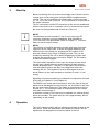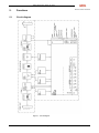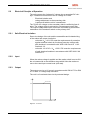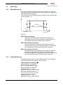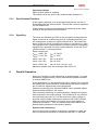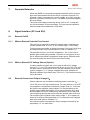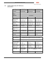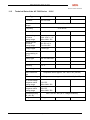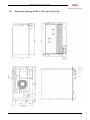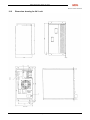
1
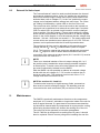
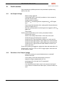
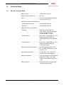
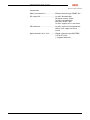
Operating Instructions
Switch Mode Power Supply
AC 7000
AEG SVS Power Supply Systems GmbH
Department: SVS V131
Name: Schenuit / Wes
Alteration state: 09
Date: 09.01.2008
Operating Instructions
0208 BAL, en
Switch Mode Power Supply AC 7000
Table of Contents
Notes on these operating instructions ............................................3
1.
1.1
1.2
1.3
1.4
1.5
Safety Regulations!................................................................5
Important Instructions and Explanations ..................................5
Accident Prevention Regulations .............................................5
Qualified Personnel..................................................................5
Liability .....................................................................................6
Regulations ..............................................................................6
2.
2.1
General Information ...............................................................7
Type Overview .........................................................................7
3.
Start-Up ...................................................................................8
4.
Operation ................................................................................8
5.
5.1
5.2
5.2.1
5.2.2
5.2.3
5.2.4
5.2.5
5.2.6
5.3
5.3.1
5.3.2
5.3.3
5.3.4
Functions ................................................................................9
Circuit diagram .........................................................................9
Electrical Principle of Operation .............................................10
Safe Electrical Isolation..........................................................10
Input .......................................................................................10
Output ....................................................................................10
Dynamic Response of the Output Voltage .............................11
Emitted Interference...............................................................11
Setting the Output Voltage and the Output Current ...............11
Monitoring ..............................................................................12
Mains Monitoring....................................................................12
Output Monitoring ..................................................................12
Reset Buttons/Functions ........................................................13
Signalling ...............................................................................13
6.
Parallel Operation ................................................................13
7.
Separate Networks...............................................................14
8.
8.1
8.1.1
8.1.2
8.2
8.3
Signal Interface (X13 and X14)............................................14
External On/Off ......................................................................14
With an External Potential-Free Contact................................14
With an External DC Voltage Source (Option) .......................14
External Sensor Lead Output Voltage UA..............................14
External Set Value Input ........................................................15
9.
Maintenance .........................................................................15
10.
10.1
10.2
Fault Location.......................................................................16
No Output Voltage..................................................................16
Deviation of the Output Voltage .............................................16
11.
11.1
11.2
11.3
Technical Data......................................................................17
General Technical Data .........................................................17
Technical Data of the AC 7000 Series 24 V to 106 V ............20
Technical Data of the AC 7000 Series 212 V......................21
12.
12.1
12.2
Dimension Drawings............................................................22
Dimension drawings for 48 V, 106 V and 212 V units............23
Dimension drawing for 24 V unit ............................................24
Page 2 of 24
0208 BAL, en
Switch Mode Power Supply AC 7000
Notes on these operating instructions
Instruction Obligation
These operating instructions must be read carefully by all persons
working with or on the switch mode power supply prior to installation
and initial start-up.
These operating instructions are a composite part of the switch mode
power supply.
The operator of this device is obliged to communicate these instructions to all personnel transporting or starting the switch mode power
supply or performing maintenance or any other work on the unit.
Validity
These operating instructions comply with the current technical specifications of the switch mode power supply at the time of publication.
The contents do not constitute a subject of contract, but serve information purposes only.
AEG reserves the right to make modifications with regard to contents
and technical data in these operating instructions without prior notification. AEG cannot be held liable for any inaccuracies or inapplicable
information in these operation instructions, as no obligation to continuously update the data and maintain their validity has been entered
into.
Warranty
Our goods and services are subject to the general conditions of supply for products of the electrical industry and our general sales conditions. We reserve the right to alter any specifications given in these
operating instructions, especially with regard to technical data, operation, weights and dimensions. Claims in connection with supplied
goods must be submitted within one week of receipt along with the
packing slip. Subsequent claims cannot be considered.
AEG will rescind all obligations such as warranty agreements, service
contracts etc. entered into by AEG or its representatives without notice in the event of maintenance and repairs being carried out with
anything other than original AEG parts or spare parts purchased by
AEG.
Handling
These operating instructions for the SMPS are structured so that all
work necessary for starting up, maintenance and repair of the unit
can be performed by qualified personnel.
Illustrations are provided to elucidate and facilitate certain worksteps.
If any work possibly involves danger to personnel and the unit, it is
highlighted accordingly by pictograms explained in Chapter 1, Safety
Instructions.
Page 3 of 24
0208 BAL, en
Switch Mode Power Supply AC 7000
Hotline
Our service department is at your disposal for any questions on the
Hotline number given below:
AEG SVS Power Supply Systems GmbH
Emil-Siepmann-Straße 32
D-59581 Warstein
(0049 2902) 763-100
FAX (0049 29 02) 763-680
http://www.aegsvs.de
Copyright
No part of these operating instructions may be reproduced or transmitted by any mechanical or electronic means without the express
prior written permission of AEG.
©
Copyright AEG 1996. All rights reserved.
Page 4 of 24
0208 BAL, en
Switch Mode Power Supply AC 7000
1.
Safety Regulations!
1.1
Important Instructions and Explanations
The instructions for operation and maintenance as well as the following safety regulations must be complied with to safeguard the safety
of personnel as well as the function of the unit. All personnel installing/dismantling, starting up, and servicing the unit must be familiar
with and observe these safety regulations. Only qualified personnel
may perform the described work with suitable and intact tools, equipment, test equipment and materials.
1.2
Accident Prevention Regulations
Compliance with the accident prevention regulations valid in the
country of application and the general safety regulations in accordance with IEC 364 is mandatory.
The following must be observed prior to any work on the switch mode
power supply:
disconnect the power supply,
secure against reactivation,
verify that the unit is disconnected from the power supply,
earth and short the circuit,
cover or isolate any neighbouring power-supplied units.
1.3
Qualified Personnel
The SMPS may only be transported, installed, connected, started,
serviced and operated by qualified personnel who are familiar with
the pertinent safety and installation regulations. All work performed
must be inspected by responsible experts.
The qualified personnel must be authorised to perform the work by
the competent safety officer.
Qualified personnel is defined as personnel
having completed training and gained experience in the respective field,
familiar with the pertinent standards, rules and regulations and
accident prevention regulations,
having received instruction on the mode of operation and operating conditions of the switch mode power supply,
capable of recognising and preventing dangers.
Regulations and definitions for qualified personnel are contained in
DIN 57105/VDE 0105, Part 1.
Page 5 of 24
0208 BAL, en
Switch Mode Power Supply AC 7000
1.4
Liability
No liability is accepted if the switch mode power supply is used for
applications not intended by the manufacturer. Any necessary measures for prevention of injury or damage to equipment is the responsibility of the operator or user. In the event of any claims in connection
with the switch mode power supply please contact us quoting:
-
1.5
the type designation,
works number,
reason for claim,
period of use,
ambient conditions,
operating mode.
Regulations
The SMPS devices comply with current DIN and VDE regulations.
VBG4 is met on the basis of compliance with the regulation VDE
0106, Part 100.
The specifications of VDE 0100, Part 410, "Functional extra-low voltage with safe isolation" are complied with when applicable.
The CE conformity symbol on the unit confirms compliance with EC
framework directive for 73/23 EEC - low voltage and for 89/339 EEC electromagnetic compatibility, if the installation and start-up instructions described in the operating instructions are observed.
Page 6 of 24
0208 BAL, en
Switch Mode Power Supply AC 7000
2.
General Information
The switch mode power supply type AC 7000 (also referred to as
SMPS) supplies an output capacity of approximately 7 kW. Typical
applications are installation as a mains power supply unit or as a secured power supply unit with a battery connected in parallel. The
positive dynamic control properties in the event of input voltage fluctuations and sudden load variations are particularly advantageous.
The switch mode power supply works in accordance with an IU curve
in accordance with DIN 41772 or DIN 41773. It is a preassembled
unit which is ready for connection. The connections are provided on
the front of the unit for easy access. The operating and indicating
elements are installed on the front of the unit.
Due to its high degree of efficiency (refer to the technical data sheet)
the unit is of compact design as a 19 inch panel mounting unit with
four height modules. It is ready for installation in a module rack according to DIN 41494.
2.1
Type Overview
Type designation
E number
Connection Output
voltage
voltage
Outputcurrent
D400 G24/220 BWrug-CFü 763 720 5602 3x400V AC
24 V DC 220 A
D400 G48/125 BWrug-CFü 763 720 5702 3x400V AC
48 V DC 125 A
D400 E106/60 BWrug-CFü 763 720 8202 3x400V AC 106 V DC
60 A
D400 G212/30 BWrug-CFü 763 720 5902 3x400V AC 212 V DC
30 A
Page 7 of 24
0208 BAL, en
Switch Mode Power Supply AC 7000
3.
Start-Up
Before connecting the unit to the mains supply ensure that the mains
voltage given on the rating plate complies with the supplied mains
voltage. The unit is connected to the mains with a 3-pole connector
(L1, L2, L3) on the front of the unit. A PE connection is not provided in
the mains connector.
The DC connection and the PE connection of the unit are established
with the connection bolt or connection rail or by a terminal link behind
the cover on the right-hand side of the front of the unit.
i
NOTE:
The discharge current exceeds 3.5 mA. Prior to start-up a PE
conductor connection must be established. Sole utilization of
r.c.c.b. devices is not permissible. Refer to Chapter 11, Technical
Data, for the set output voltage.
i
NOTE:
The unit has an amplified smoothing module with large electrolytic
capacitors on the output side. If the de-energized capacitors are
switched over to the battery by engaging the DC isolator or DC
fuse this causes a large surge of charging current. This can be
avoided by switching the unit on before engaging the isolator and
charging the capacitors to the unit output voltage. The DC isolator
or fuse can then be engaged.
The unit contains capacitors in the input and output circuits which
can still carry voltage when the mains voltage has been disconnected (discharge time > 1 minute). For this reason the terminals
must be tested to ensure that they are voltage-free before dismantling the unit. The capacitors must be discharged via an external resistor on the main terminals or terminals L+ and L- if necessary.
Signalling and external coupling is performed via connectors X13 and
X14 (refer to Chapters 5.1 and Chapter 8.) .
The SMPS is air cooled with a fan taking in air at the front of the unit
which is then discharged from the unit rear. Air circulation to and from
the fan must not be obstructed. The intake air temperature must not
exceed 45 °C. The maximum intake air temperature for the cabinet
must also not exceed 40 °C
A maximum number of five units may be installed in a cabinet directly
above one another. The power loss per unit is approximately 600 W
(depending on the model).
4.
Operation
The unit is operated solely with the operating elements located on the
front panel. These are described in the respective chapters and assigned with the designations on the front panel of the unit.
Page 8 of 24
0208 BAL, en
Switch Mode Power Supply AC 7000
5.
Functions
5.1
Circuit diagram
Figure 1: Circuit diagram
Page 9 of 24
0208 BAL, en
Switch Mode Power Supply AC 7000
5.2
Electrical Principle of Operation
The unit converts the 3-phase AC voltage into a smoothed DC voltage. Transistors convert this to an AC voltage at 75 kHz.
Electrical isolation and
voltage adjustment to the secondary side
is performed with the aid of a transformer.
The 75 kHz AC voltage on the secondary side is rectified by fast diodes. The voltage ripple is reduced by a downstream output filter.
The output voltage and output current are controlled by pulse widen
modulation of the transistor switch on the primary side.
5.2.1
Safe Electrical Isolation
Due to the design of the unit and the assemblies and isolated wiring
of the mains and output circuits the
units with UA ≤ 60 V DC meet the requirements of protection
against electrical shock by functional extra-low voltage with
safe isolation in accordance with VDE 0100 Part 410 11.83
Section 4.3.2 .
units with 110 V DC ≤ UA ≤ 220 V DC meet the requirements
of safe electrical isolation in accordance with VDE 0160 5.88
Section 5.6 .
5.2.2
Input
When the mains voltage is applied and the mains switch is set to ON
the unit starts with an acceleration stage which limits the make current to the rated input current level (soft start).
5.2.3
Output
The output curve is an IU curve in accordance with DIN 41772 or DIN
41773 with 1% voltage step inclination.
The unit is of continued short-circuit protected design.
U
o
1% Inc lina tio n
100%
I
ra te d
I
o
Figure 2: IU curve
Page 10 of 24
0208 BAL, en
Switch Mode Power Supply AC 7000
5.2.4
Dynamic Response of the Output Voltage
In the event of sudden load fluctuations between 10% and 90% Irated
or 90% and 10% Irated the voltage deviation is U < 3 % and is compensated within t < 1 ms.
5.2.5
Emitted Interference
The SMPS meets the specifications of the limit value class "B" in accordance with EN 55011/55022. (please also refer to Chapter 11,
General Technical Data).
5.2.6
Setting the Output Voltage and the Output Current
The setting values of the output voltage, the output current and the
monitoring devices are given in the pertinent technical data (refer to
Chapter 11).
i
NOTE:
In the case of battery voltage deviation the output voltage must be
adjusted. The output voltage is adjustable with the UA potentiometer within in a limited range.
Proceed as follows:
Disconnect the load and the battery if applicable on the output.
Set the required monitoring values with the UA> and UA< potentiometers with a screwdriver.
UA> Adjustment:
set the UA> potentiometer to the far right stop,
-
set the UA to the required UA > value,
-
turn the UA> potentiometer to the left until UA > responds
UA< Adjustment:
Performed as for UA> adjustment (observe the discharge time
of the output capacitors and monitoring delay).
Connect the load/battery
Set the UA output voltage to the required value with the UA
potentiometer.
The maximum output current is also adjustable within a limited range
with the IA potentiometer.
However, the factory setting must only be adjusted in exceptional cases!
Proceed as follows:
Increase the load until the set current limitation is triggered
Adjust the IA potentiometer with a screwdriver (IA smaller
when turned to the left).
Page 11 of 24
0208 BAL, en
Switch Mode Power Supply AC 7000
5.3
Monitoring
5.3.1
Mains Monitoring
The mains monitoring assembly fulfils various functions. It ensures
the intrinsic safety of the unit against overloads and overvoltages with
fixed switching point settings.
The response values (switching points) are given in the technical data
(refer to Chapter 11).
On
Hysteresis
(Shutd ow n hysteresis ra ng e)
Off
Und ervolta g e
U ma ins[V]
Overvolta g e
Figure 3:
Phase failure monitoring
The mains monitoring device detects phase failure and
switches the unit off. When the phase is registered the unit
automatically resumes operation with a "soft start".
Mains undervoltage monitoring
The unit is switch off if the mains supply drops below the
switching point. When the hysteresis voltage is exceeded the
unit automatically resumes operation with a "soft start".
Mains overvoltage monitoring
When the maximum permissible mains voltage is exceeded
the SMPS is stopped for the duration of the overvoltage.
When the voltage level drops below the hysteresis voltage the
unit automatically resumes operation with a "soft start".
5.3.2
Output Monitoring
The setting potentiometers and the LED indicators for the following
monitored functions are located on the front plate:
Overtemperature monitoring ϑG
with deactivation and latching.
DC-overvoltage indicator UA>
with deactivation and latching
(response delay t = 10 ms)
Adjustment with UA> potentiometer
DC-undervoltage indicator UA<
without delay, without latching
(response delay t = 2,8 s)
Adjustment with UA< potentiometer
Page 12 of 24
0208 BAL, en
Switch Mode Power Supply AC 7000
Operating indicator
lights up when power is supplied
The setting values are given in the technical data (Chapter 11).
5.3.3
Reset Buttons/Functions
A fault signal (response of an output monitoring device) can be acknowledged with the "Reset" button. The unit then resumes operation
if it was switched off.
A fault signal can also be acknowledged by switching off the mains
voltage or with the external on/off function.
5.3.4
Signalling
The faults are indicated by LEDs on the front panel and signalled on
signal connector as a collective signal via a potential-free relay contact (changeover contact) on signal connector X14. The contact between X14:8 and X14:9 is closed in the event of unit failure or a fault.
The response of the overtemperature monitoring device is separately
signalled via a potential-free relay contact between X14:6 and X14:7
(contact closed--> overtemperature).
Relay contact load:
Umax = 250 V DC
Iper <0,2 A DC
Umax = 110 V DC
Iper <1 A DC
Umax = 60 V DC
Iper <0.45 A DC
Umax = 24 V DC
Iper <8 A DC
Umax = 250 V AC
Iper <8 A AC, at cos ϕ >0.6
Maximum isolation from the secondary side: 250 V AC
6.
Parallel Operation
Due to the inclination of the voltage step of approximately 1% a load
distribution of approximately 10% is achieved with parallel operation
of several SMPS units.
If load distribution is to be optimized the output voltage of the unit with
the lowest load current should be increased and the output voltage of
the unit with the highest load current decreased.
Selective monitoring of the individual SMPS units is possible without
external isolating diodes in the output.
This is done by monitoring an internal auxiliary voltage that is generated in parallel to the output voltage. This monitoring is only used for
unit monitoring (accuracy ±1 V of the actual unit output voltage). If
accurate output voltage monitoring is required, then DIP-Fix switch
S503 on printed circuit board A1 must be moved from position 2
(standard) to position 1. This only makes sense when SMPS units
with decoupling diodes are connected in parallel.
Systems with redundancy:
As the units can be connected in parallel it is possible to create systems for redundant operation in accordance with the n+1 principle.
Page 13 of 24
0208 BAL, en
Switch Mode Power Supply AC 7000
7.
Separate Networks
When the SMPS is connected to separate networks, mains overvoltages must be expected which can last for a period of seconds. For
example if rotary converters are used for supply, up to 20% overvoltage over a period of seconds occurs. The SMPS is protected against
this overvoltage.
The mains overvoltage monitoring device (refer to 4.3.1) stops the
unit for the duration of the overvoltage. The unit resumes operation
when the peak has resided with a "soft start".
8.
Signal Interface (X13 and X14)
8.1
External On/Off
8.1.1
With an External Potential-Free Contact
The unit can be switched on and off externally with a potential-free
contact (contact load 12 V DC / 6 mA, contact open = "Unit Stop").
To this purpose the bridge on signal connector X14:1 and X14:2 must
be removed and a relay contact looped in (refer to Chapter 5.1).
The potential of X14:1 and X14:2 is applied to - UA. In the case of
positive pole earthing the potential - UA which is now higher (in relation to reference potential) is applied to these inputs. Electrical isolation must therefore be carried out by the external relay.
8.1.2
With an External DC Voltage Source (Option)
It is also possible to switch the unit on and off with a DC voltage
source U = 5 - 24 V DC (maximum load 20 mA at 24 V DC). The positive pole must be connected to X14:1 and the negative pole to X14:2
(refer to Chapter 5.1). If voltage is applied the unit is switched off.
Electrical isolation is provided (max. 250 V AC). This function must be
set at the works!
8.2
External Sensor Lead Output Voltage UA
Sensor leads are not provided for switching power units with UA ≥
110 V DC due to the high voltage levels. For units with UA ≤ 60 V DC
it is possible to compensate a maximum voltage drop of 1 V on both
the positive and negative output cables. For compensation on the
positive output cable the bridge 9-10 on signal connector X13 must
be interrupted and X13:9 connected to the positive pole of the load.
The monitoring devices then still monitor the positive pole of the unit.
For monitoring the negative output cable, bridge 7 - 8 on signal connector X13 must be interrupted and X13:7 connected to the negative
pole of the load (refer to Chapter 5.1).
If the sensor lead is interrupted the output voltage increases by approximately 1.5 V in each case.
Page 14 of 24
0208 BAL, en
Switch Mode Power Supply AC 7000
8.3
External Set Value Input
The "internal/external" switch is used to switch between the internal
and external voltage set value. In the "int" position the unit works in
basic mode with the output voltage and current values stated in the
technical data (refer to Chapter 11). In the "ext" position the output
voltage can be adjusted with an external set value input. The "external" setting is indicated by a yellow LED on the front of the unit.
The current set value function is set at the works to the internal set
value and can be switched to an external set value input if required.
(DIP-Fix switch S501 on printed circuit board A1 must be changed
over to position 2 for this purpose.) The set value setting for voltage
and/or current is performed on signal connector X13 with the signals
shown in the circuit diagram. It must be ensured that the voltage drop
between - UA and - Uset does not exceed 1 V. The rated voltage and
current values are reached at a set value input of 4.0 V DC. Fine adjustment can be performed with the UA and IA potentiometers.
The monitoring devices must be adjusted to the respective output
voltage with the UA> and UA< potentiometers (refer to Chapter
5.2.6). The inputs for external set values are galvanically connected
to the - UA output! In order to obtain defined conditions the earth
connection of the external set value inputs (X11:3 and X11:5) must be
connected to the unit earth X13:1.
9.
i
NOTE:
There is no electrical isolation of the unit output voltage UA, i.e. if
the positive pole is earthed the output voltage potential is applied
to these inputs! To avoid a short circuit the external set value input must be electrically isolated from the SMPS.
With the SMPS it is also possible to address an external voltage
divider with the unit voltage of +7.5 V in order to achieve the external set value input. The maximum load current of the +7.5 V
voltage must then not exceed 10 mA.
i
NOTE for sections 8.1.2 and 8.3::
To obtain noise immunity to high-frequency fields, screened cables must be used for analogue signals. The shielding must be
connected to the earth connection (PE) on the front of the unit.
Maintenance
The SMPS is practically maintenance-free due to the components
employed. It is, however, advisable to inspect the inside of the unit for
dust at regular intervals. If a great deal of dust has accumulated the
unit should be cleaned with dry compressed air to prevent the cooling
effect being impaired which can shorten the working life of the unit.
The unit must not be operated in corrosive atmospheres.
The AC 7000 fan is designed for a working life of 8 years. It should
then be replaced. Ensure correct poling when installing the new fan.
Page 15 of 24
0208 BAL, en
Switch Mode Power Supply AC 7000
10.
Fault Location
Only trained and qualified personnel are permitted to perform any
work on the unit.
10.1
No Output Voltage
Mains voltage applied?
Is the bridge X14:1 and X14:2 provided or is the contact for
external on/off closed?
Output poled incorrectly?
Has the UA> monitoring device responded (UA> LED lights
up)?
Press reset and check the UA> setting with UA potentiometer
(refer to Chapter 5.2.6).
Has the overtemperature monitoring device triggered (LED ϑG
lights up)?
Press reset!
If all the points listed above are in order, proceed as follows:
Unscrew the cover!
Observe the safety instructions on the front of the unit!
Check the plug connections for correct fit!
Check fuse F1 (Type 6x32 M 2 A 500 V) on circuit card A1.
Check fuse F2 (Type 5x20 T 0.25 A 250 V) on circuit card A1.
Check fuse F3 (Type 5x20 T 0.25 A 250 V) on circuit card A1.
Check fuse F1 (Type 6,600 CP URD 22x58 63 A 660 V) on
circuit card A10.
If one of the fuses has triggered, replace the fuse and restart the unit.
If fuses A1-F1, A1-F2, A1-F3 or A10-F1 trigger again, return the unit
to the works for repair.
-
10.2
Deviation of the Output Voltage
-
Is the unit running in current limitation due to overload?
Reduce the load!
Is the setting of the UA potentiometer incorrect?
Adjust the output voltage (refer to 5.2)!
Are bridges X13:9-10 and X13:7-8 provided?
Fit the bridges!
If an external sensor lead is used, is the sensor lead open?
In the case of an external set value input, is the set value correct?
Page 16 of 24
0208 BAL, en
Switch Mode Power Supply AC 7000
11.
Technical Data
11.1
General Technical Data
Make current.................................. ≤ Rated input current
Required mains protection............. gL 16 A
Curve ............................................. IU curve in accordance with DIN
41772 or DIN 41773
Emitted interference to EN 50081-1
- Conducted interference ............... to EN 55022 Class "B"
- Emission...................................... to EN 55022 Class "B"
Noise immunity to EN 50082-2
- Housing ....................................... ESD test to EN 61000-4-2,
6 kV contact, 8 kV air discharge
HF field to EN 61000-4-3,
10 V/m (30 MHz - 1 GHz)
- Power cables ............................... Burst test to EN 61000-4-4, 2 kV
Surge test to EN 61000-4-5,
4 kV asymmetrical 2 kV symmetrical
- Control cables ............................. Burst test to EN 61000-4-4, 2 kV
Surge test to EN 61000-4-5,
2 kV asymmetrical
Functional extra-low voltage .......... with safe isolation at UA ≤ 60 V
DC to VDE 0100 Part 410 11.83
Section. 4.3.2
Safe electrical isolation.................. at 110 V DC ≤ UA ≤ 220 V DC :
to VDE 0160 5.88 Section 5.6
Dynamic response......................... ≤ 3% with sudden load fluctuations
between 10%-90%-10% rated
output current (adjustment time t <
1 ms)
Short circuiting............................... continued short-circuit protected,
1 x rated output current
Page 17 of 24
0208 BAL, en
Switch Mode Power Supply AC 7000
Monitoring:..................................... - Phase failure, self- acknowled
ging
- Mains undervoltage with deacti
vation, self-acknowledging
- Mains overvoltage with deactiva
tion, self-acknowledging
- Overtemperature with
deactivation and latching
- DC undervoltage without
deactivation, self-acknowledging
- DC overvoltage with deactivation
and latching,
Indication ....................................... - Operation with LED
- Set value internal/external with
LED
- UA and IA with analogue
measuring instruments
External functions .......................... - Collective fault signal via
potential-free relay contact
- Overtemperature via
potential-free relay contact
- ON/OFF via external
potential-free contact
- External sensor cable output
voltage UA
- External set value input 0 to 4
V DC for UA and IA, with LED
indication
Parallel operation........................... - Unlimited number, load distribu
tion approximately 10%
Design ........................................... 19" panel mounting unit for installation in module rack to DIN 41494
Protection category........................ IP 20
Cooling .......................................... Forced cooling
Ambient temperature ..................... 0°C to 45°C
0°C to 40°C for cabinet installation
Storage temperature - 30°C to +
70°C
Environmental conditions .............. IEC 721 Part 3-3 Class 3K3 / 3Z1 /
3B1 / 3C2 / 3S2 / 3M2
Site altitude.................................... up to 1000 m above sea level.
Mechanical stability and
and vibration resistance................. to VDE 0160 Version 5.88 Item
7.2.2
Surface painted with ...................... RAL 7032 (Front plate)
Page 18 of 24
0208 BAL, en
Switch Mode Power Supply AC 7000
Connections
Mains connection X1: .................... Elbow connector type GDME 313*
DC output X2: ................................ for 48 V threaded bolt
M10 max. torque 10 Nm
for 220 V threaded bolt
M6 max. torque 3 Nm
for 24 V copper rail 11 mm bores
PE conductor: ................................ for 48 V, and 220 V threaded bolt
M6 for 24 V copper rail 9 mm
bores
Signal interface X13, X14: ............. Signal connector type MVSTBW
2.5/10-ST-5,08*
(* supplied with unit)
Page 19 of 24
0208 BAL, en
Switch Mode Power Supply AC 7000
11.2
Technical Data of the AC 7000 Series
24 V to 106 V
Type
E number
G24/220
G48/125
G106/60
763 720 5602
763 720 5702
763 720 8202
Rated connection
voltage
3 x 400 V AC ± 10%
Frequency
47 to 63 Hz
Current input
3 x 10.5 A AC
3 x 11.3 A AC
3 x 12.0 A AC
Output voltage
Set value
Setting range
26.8 V DC ± 1 %
18 to 32 V DC
53.5 V DC ± 1 %
35 to 62 V DC
118.2 V DC ± 1 %
105 to 135 V DC
Output current
Set value
Setting range
220 A DC ± 2 %
150 to 220 A DC
125 A DC ± 2 %
75 to 125 A DC
60 A DC ± 2 %
25 to 60 A DC
Voltage ripple
< 10 mV pp
< 10 mV pp
< 20 mV pp
Interference voltage according to
CCITT
< 1.0 mV
< 1.8 mV
Battery type
11-12 lead cells
23-24 lead cells
53-55 lead cells
Power factor
0.92
0.94
0.92
Efficiency
89 %
91 %
91.0 %
Monitoring:
Mains undervoltage
Response values approx. 325 / 300 V AC (On/Off)
Mains overvoltage
Response values approx. 445 / 460 V AC (On/Off)
DC undervoltage
Response value
Setting range
24 V DC
18 to 28 V DC
48 V DC
35 to 60 V DC
106 V DC
95 to 125 V DC
DC overvoltage
Response value
Setting range
29.5 V DC
18 to 32 V DC
56.5 V DC
35 to 62 V DC
123,5 V DC
120 to 135 V DC
Dimensions (mm)
(W x H x D)
483x265.9x400
(19" x 6 height
modules)
Weight
32.5 kg
Page 20 of 24
483 x 221.4 x 400 (19" x 5 height
modules)
31.5 kg
30.2 kg
0208 BAL, en
Switch Mode Power Supply AC 7000
11.3
Technical Data of the AC 7000 Series
Type
E number
212 V
G212/30
763 720 5902
Rated connection
voltage
3 x 400 V AC ± 10%
Frequency
47 to 63 Hz
Current input
3 x 12.0 A AC
Output voltage
Set value
Setting range
236.4 V DC ± 1 %
180 to 280 V DC
Output current
Set value
Setting range
30 A DC ± 2 %
17 to 30 A DC
Voltage ripple
< 20 mV pp
Interference voltage according to
CCITT
Battery type
106-110 lead cells
Power factor
0.93
Efficiency
91.5 %
Monitoring:
Mains undervoltage
Response values approx. 325 / 300 V AC (On/Off)
Mains overvoltage
Response values approx. 445 / 460 V AC (On/Off)
DC undervoltage
Response value
Setting range
212 V DC
180 to 280 V DC
DC overvoltage
Response value
Setting range
255 V DC
180 to 280 V DC
Dimensions (mm)
(W x H x D)
Weight
483 x 221.4 x 400 (19" x 5 height modules)
30.0 kg
Page 21 of 24
0208 BAL, en
Switch Mode Power Supply AC 7000
12.
Dimension Drawings
Figure 4 Front view
Page 22 of 24
0208 BAL, en
Switch Mode Power Supply AC 7000
12.1
Dimension drawings for 48 V, 106 V and 212 V units
Page 23 of 24
0208 BAL, en
Switch Mode Power Supply AC 7000
12.2
Dimension drawing for 24 V unit
Page 24 of 24
0208 BAL, en