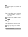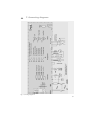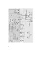
1
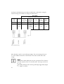
SVS POWER SUPPLY
S
THYRO-A
THYRISTOR-LEISTUNGSSTELLER
THYRO-A 1A...H RL1, 2A...H RL1
T H Y R O - A 1 A . . . H R L P, 2 A . . . H R L P
THYRISTOR POWER CONTROLLER
THYRO-A 1A...H RL1, 2A...H RL1
T H Y R O - A 1 A . . . H R L P, 2 A . . . H R L P
➜➜➜
Betriebsanleitung
Operating Instructions
Y
S
T
E
M
S
S A F E T Y
I N S T R U C T I O N S
The safety instructions and operating manual are to be carefully
read prior to installation and commissioning
Obligation to give instructions
The following safety and operating instructions must be carefully read before initial
assembly, installation and commissioning of Thyro-A by those persons working with
or on Thyro-A.
These operating instructions are part of the Power Controller Thyro-A.
The operator of this device is obliged to provide, without restriction, these operating
instructions to all persons transporting, commissioning, maintaining or performing
other work on this device.
In accordance with the Product Liability Act, the manufacturer of a product has an
obligation to provide explanations and warnings as follows:
· the use of the product other than for the intended use,
· the residual product risk,
· operating error and its consequences.
The information given below must be understood in this respect. It is to advise the
product user and protect him and his systems.
Proper use
• The Thyristor Power Controller is a component which may only be used for
control and regulation of electrical energy.
• The Thyristor Power Controller may at most be operated using the maximum
admissible connected load according to information on the type plate.
• The Thyristor Power Controller may only be operated in connection with a
suitable and series connected power supply disconnecting device (e.g. switch,
VDE 0150 T1).
• As a component, the Thyristor Power Controller is unable to operate alone and
must be projected for its intended use to minimize residual risks.
56
The Thyristor Power Controller may only be operated in the sense of its intended
use; otherwise personal hazards, (e.g. electric shocks, burns) and hazards for
systems (e.g. system overload) may arise.
Residual hazards of the product
• Even in proper use, should a fault occur, it is possible that control of currents,
voltages and power is no longer performed in the load circuit by the Thyristor
Power Controller.
In case of destruction of the power components (e.g. break-down or high resistance), the following situations are possible: power interruption, half-wave operation, continuous power flow.
If such a situation occurs, then load voltages and currents are produced from the
power circuit. It must be ensured by system design that no uncontrolled large
currents, voltages or power occur.
Malfunction and the results
With malfunction it is possible that power, voltage or flow levels which are higher
than planned reach the Thyristor Power Controller or load. In principle, this can
lead to the Power Controller or load being damaged.
Transport
Thyristor Power Controllers are only to be transported in their original packaging
(protection against damage e.g. due to jolting, knocking, soiling).
Installation
If the Thyristor Power Controller is brought into the operation room from a cold environment, moisture due to condensation can occur. Prior to it being commissioned,
the Thyristor Power Controller must be absolutely dry. Therefore, wait for a minimum of two hours before commissioning.
Connection
Prior to connection, it must be ensured that the voltage information on the type
plate corresponds with the mains voltage.
• The electrical connection is carried out at the designated points with the required
cross section cable and the appropriate screw cross sections.
57
Operation
The Thyristor Power Controller may only be connected to the mains voltage if it has
been ensured that any hazard to people and system, especially in the load section,
has been eliminated.
• Protect the device from dust and moisture
• Do not block vents.
Maintenance, service, malfunctions
CAUTION
For maintenance and repair work the Power Controller must be
disconnected from all external voltage sources and protected against
restarting. The voltage-free state is to be determined by means of suitable measuring instruments. This work is only to be carried out by a
skilled electrician. The electrical regulations which are locally valid
are to be adhered to.
CAUTION
The Thyristor Power Controller contains dangerous voltages. Repairs
may only be carried out by qualified and trained maintenance personnel.
CAUTION
Danger of electric shocks. Even after disconnection from the mains
voltage, capacitors may still contain a dangerously high power
level.
CAUTION
Danger of electric shocks. Even when the Thyristor Power Controller is
not triggered, the load circuit is not disconnected from the mains.
ATTENTION
Different components in the power section are screwed into place
using exact torques. For safety reasons, power component repairs
must be performed by AEG SVS Power Supply Systems GmbH.
S A F E T Y
58
I N S T R U C T I O N S
CONTENTS
➜
➜
➜
Safety instructions
56
Safety regulations
62
Remarks on the present operating instructions and Thyro-A 64
➜
1.
1.1
1.2
1.3
Introduction
General
Specific characteristics
Type designation
66
66
66
67
➜
2.
2.1
2.2
2.3
2.3.1
2.3.2
2.3.3
2.4
2.4.1
2.4.2
2.5
2.5.1
2.5.2
2.5.3
2.5.4
2.6
2.7
Functions
Operating modes
Set point control characteristic
Control types
Controlled value
Limitations
Controller response
Indications
LED indications
Alarm relay K1
Monitoring
Monitoring of load and mains voltage
Absolute value monitoring current
Equipment temperature monitoring
Ventilator monitoring
Set point processing when employing a bus module
Additional functions for Thyro-A
67
67
68
69
70
70
70
70
70
71
71
71
71
71
72
72
73
➜
3.
3.1
3.1.1
3.1.2
3.1.3
3.1.4
3.1.5
3.2
3.2.1
3.2.2
3.2.3
3.2.4
3.2.5
3.3
Operation
Configuration switch S1
Operating mode
Control types / analog output
Live zero set point
Set point input
Analog output
Potentiometer
Phase angle 1. half wave operation TAKT
Control end set point input
Current limitations
Increased analog output
Load monitoring (undercurrent monitoring)
Diagnosis / status indications
75
75
75
75
75
76
76
76
76
77
78
78
78
83
59
➜
4.
4.1
4.2
4.3
4.4
4.5
4.6
4.7
4.8
4.9
4.10
4.11
4. External connections
Power supply for Thyro-A
Power supply for the control device
Additional control voltage input
Pulse lock
Analog set point value input
Digital set point value input
Analog output
Current transformer
Voltage transformer
Block connection diagram
Operating elements and terminal strips
83
83
83
84
84
84
84
85
85
85
86
87
➜
5.
Interfaces
89
➜
6.
6.1
6.2
6.3
Mains load optimization
Synchronization SYT-9 (operating mode TAKT)
Synchronization in operating mode QTM (1A)
Software synchronization (operating mode TAKT)
89
90
90
90
➜
7.
Connecting plans
91
➜
8.
8.1
8.2
8.3
8.4
Special remarks
Installation
Commissioning
Service
Checklist
94
94
94
95
96
➜
9.
9.1
9.2
Type overview
Thyro-A 1A...H RL 1, ...H RLP
Thyro-A 2A...H RL 1, ...H RLP
96
97
97
➜
10.
Technical data
98
➜
11.
Dimensional drawings
101
➜
12.
Accessories and options
107
➜
13.
Approvals and conformities
107
Addresses
112
60
List of illustrations and tables
Fig.
Fig.
Fig.
Fig.
Fig.
Fig.
Fig.
Fig.
Fig.
Fig.
Fig.
Tab.
Tab.
Tab.
Tab.
Tab.
Tab.
Tab.
Tab.
1
2
3
4
5
6
7
8
9
10
11
1
2a
2b
2c
2d
3
4
5
Control characteristic
Set point inputs and total set point
Block connecting diagram
Terminal plan
Operating elements
Thyro-A...H RL1, ...H RLP
Connecting diagram 1A
Connecting diagram 2A
Connecting diagram for auxiliary supply and bus module
Connecting diagram for QTM
Connecting diagram for SYT9
68
69
86
87
88
89
91
92
93
93
93
Behaviour with load change
Load monitoring
Load monitoring
Load monitoring
Load monitoring
Allocation of message register
Default values DIP switch S1
Default values potentiometer
70
79
80
81
82
83
94
95
61
➜
Safety regulations
Important instructions and explanations
Operation and maintenance according to regulations, as well as observance of the
listed safety regulations is required for the protection of the staff and to maintain readiness to operate. Personnel assembling/disassembling the devices, commissioning
them, operating them and maintaining them must know and observe these safety
operations.
In the present operating instructions important instructions are marked using the
terms “CAUTION”, “ATTENTION” and “REMARK” as well as using the icons
explained below.
CAUTION
This instruction indicates work and operating procedures to be observed exactly to exclude hazards to persons.
ATTENTION
This instruction refers to work and operating procedures to be observed exactly to avoid damage or destruction of Thyro-A or parts thereof.
NOTE
This is where remarks on technical requirements and additional information is given which the user must observe.
Accident prevention rules
It is imperative that the accident prevention rules of the country of application and
the generally applicable safety regulations are observed.
CAUTION
Before starting any work on Thyro-A, the following safety regulations
must be observed:
• switch voltage-free
• secure against switching on
• determine voltage-free state
• ground and short-circuit device
• cover or block neighbouring parts under voltage
62
Qualified personnel
Thyro-A may only be transported, installed, connected, commissioned, maintained
and operated by specialists in command of the respective applicable safety and installation regulations. All work must be monitored by the responsible specialist personnel.
Intended use
CAUTION
The Thyristor Power Controller may only be employed in the sense of
its purpose of use (see the section of the chapter on safety instructions
under the same name), otherwise hazards to persons (e.g. electric
shocks, burns) and systems (e.g. overload) may occur.
Any unauthorized reconstruction and modification of Thyro-A, use of spare and exchange parts not approved by AEG SVS as well as any other use of Thyro-A is not
permitted.
The person responsible for the system must ensure that:
- safety and operating instructions are available and observed,
- operating conditions and specifications are observed,
- protective installations are used,
- maintenance personnel are immediately notified or Thyro-A is immediately put out
of commission if abnormal voltages or noises, higher temperatures, vibrations or similar occur to determine the causes.
These operating instructions contain all information required by specialists for the
use of Thyro-A. Additional information and notes for unqualified persons and for the
use of Thyro-A outside of industrial installations are not contained in these operating
instructions.
The warranty obligation of the manufacturer applies only if these operating instructions are observed.
Warranty
No liability is assumed when using Thyro-A for applications not provided for by the
manufacturer. The responsibility for the necessary measures to avoid hazards to persons and property is borne by the operator or the user. In case of complaints on
Thyro-A, please notify us immediately stating:
Type name, production number, complaint, ambient conditions, operating mode,
duration of use.
63
➜
Remarks on the present operating instructions
and Thyro-A
Validity
The following operating instructions describe the type range Thyro-A of models
...H RL and H RLP. Product characteristics which are only available for the type
range Thyro-A...H RLP are marked with (H RLP).
These operating instructions correspond to the technical state of Thyro-A at the time
of publication. The contents are not subject matter of the contract, but serve only as
information. Modification of information contained in these operating instructions,
especially technical data, operation, dimensions and weights, remain reserved at
any time. AEG SVS reserves the right to content modifications and technical changes within the present operating instructions without obligation of notification. AEG
SVS is not obliged to update these operating instructions constantly.
Handling
These operating instructions for Thyro-A are set out so that all work required for commissioning, maintenance and repair may be performed by corresponding specialist
personnel.
Abbreviations
In this description the following specific abbreviations are used:
AEG SVS
SYT
TAKT
VAR
=
=
=
=
AEG SVS Power Supply Systems GmbH
synchronized clock
full wave switch mode Thyrotakt
phase-angle mode Thyrovar
Loss of warranty
Our supplies and services are subject to the general terms and conditions of delivery
of the electrical industry as well as our general sales conditions. Any complaints on
goods delivered are to be submitted, together with the delivery note, within eight
days of receipt.
All guarantees made by AEG SVS and its dealers will be cancelled without prior
notice if other than original AEG SVS spare parts or spare parts purchased by
AEG SVS are used for maintenance and repair.
64
Copyright
Passing on, duplication and/or takeover of these operating instructions by electronic
or mechanical means, including excerpts, is subject to the express prior written
approval of AEG SVS.
Copyright AEG SVS Power Supply Systems GmbH 2003.
All rights reserved.
Further Copyright advice
Thyro- is an internationally registered trademark of AEG SVS Power Supply Systems
GmbH.
Windows and Windows NT are registered trademarks of the Microsoft Corporation.
All other companies and product names are the (registered) trademarks of the
respective owners.
65
➜
1. Introduction
Thyro-A has been conceived to meet the demands for simple assembly, speedier
commissioning and safer operation.
For transport, assembly, installation, commissioning, operation and decommissioning, it is essential that the safety instructions included in these operating instructions
are observed and made available to all persons handling this product.
In case of uncertainties or missing information, please contact your supplier.
The described operating mode QTM is in preparation.
1.1 General
Thyro-A is a Thyristor Power Controller with the ability to communicate. It will also
simply be referred to as Power Controller or Controller. It can be used wherever voltages or currents need to be controlled or regulated in processing technology.
Thyro-A’s distinguishing features are its several operating and control modes, good
coupling ability to process and automation technology, high control precision and
simple handling through a 16-Bit processor.
1.2 Specific characteristics
Thyro-A has a wide range of distinguishing features, for instance:
➜ easy handling
➜ type range 230-500V, 8-280A, single and double phase with additional 24V
24V control voltage power supply also for mains voltages 0.43 x Unom
➜ ohmic load and transformer load, as well as load with large Rhot /Rcold ( 6)
peak current limit to 3 x Inom
➜ soft start function for transformer load
➜ channel separation, required with countervoltage
➜ load circuit monitoring
➜ relay indication
➜ control modes U, U2, I, I2 as well as P-control with H RLP)
➜ operating modes TAKT, as well as VAR and QTM with Thyro-A 1A
➜ control with analog set points and / or via optional bus adapter
➜ series system interface
➜ electrical separation according to EN 50178 chapt. 3
Options:
➜ bus connections via bus adapter.
Coupling to different bus systems, e.g. Profibus DP, Modbus RTU, other bus
systems on request.
66
1.3 Type designation
The type designation of the Thyristor Power Controllers is derived from the construction of its power section:
Thyro-A 1A Thyristor controller with single phase power section
suited for single phase loads
Thyro-A 2A Thyristor controller with double phase power section
suited for symmetrical loads in three phase operation in
three phase saver circuit
Example
Thyro-A 1A Thyristor controller with single phase power section
...400with 400 Volt type voltage
...280
with 280 Ampere type current
H
with integrated semi-conductor fuse
F
with ventilator (only 280 Ampere types)
R
with indication relay
L with load monitoring
P with additional power control
1 designation Thyro-A, 2002 series
The complete type range can be found in chapter 9, TYPE OVERVIEW.
➜
2. Functions
To enable Thyro-A to adjust optimally to the desired application, it is equipped with
a wide range of functions. These are described below. Further functions are possible
by applying Thyro-A within a bus system. See also chapter 5 INTERFACES.
2.1 Operating modes
For optimum adjustment to different applications and production processes, as well
as different electrical loads, the most favourable operating mode can be set.
Full wave switch TAKT (for 1A, 2A)
Depending on the prescribed set point, the mains voltage is periodically switched. In
this operating mode almost no harmonics are created. Whole multiples of the mains
periods are switched, thus avoiding d.c. components. The full wave switch mode is
especially suited for loads with thermal inertia. Depending on the function angle 1.
half wave, the phase frequency is adjusted independently to 5 or 50 mains
periods = T0.
67
The TAKT operating mode creates minimal mains reactions. Should there be a
flicker, this can be minimized with the aid of the mains load optimization.
Phase-angle principle VAR (for 1A)
Depending on the prescribed set point, the sine oscillation of the mains voltage is
gated using a larger or smaller control angle . This operating mode is characterized by high control dynamics. With phase-angle control harmonics of the mains
voltage occur. It is possible to compensate these by using circuit variants.
Half-wave switch mode QTM (Quick-Takt-Mode for 1A)
QTM is the patented fast operating mode which works on the half wave switch principle. Depending on the prescribed set point, mains half waves are switched. D.c.
components are avoided for the phase duration. The fast phase control is particularly suited for IR beams as an alternative to phase-angle control. When using several
controllers it is possible, by synchronisation, to keep the mains reactions small.
2.2 Set point control characteristic
The set point control characteristic of Thyro-A can easily be adapted to the control
output signal of an upstream process controller or automation system. All signals
customary on the market may be used. The adaption is made by changing the
starting and ending points of the control characteristic.
1,6 k
1,4 k
1,2 k 1,0 k
0,8 k
0,6 k
0,4 k
Fig. 1 Control characteristic
68
If the controller is within a limit (Umax, Imax, Pmax), both LED PULSE INHIBIT and LOAD
FAULT blink alternatively in second intervals (chapt. 3.3).
Input set points
The Power Controller Thyro-A is equipped with two input set points which are
isolated from the mains, of which only one is always active.
• Set point 1 analog (X2.4 – X2.3 ground)
• Set point 2 via bus module
The analog input can be adapted to the various process controllers by means of
the set point and live zero switches as well as the potentiometer controlling set point
input. The following signal ranges can be set:
0(4)-20 mA (Ri = ca. 250 ), 0-5 V (Ri = ca. 44 k), 0-10 V (Ri = ca. 88 k).
+5V supply voltage can be taken for a set point potentiometer from terminal X2.8.
(5 k RPoti 10 k)
The effective set point is the patched through set point. Within the stated input
ranges these values with the control characteristic may be adjusted to any common
signal characteristic.
Fig. 2 Set point inputs and total set point
2.3 Control types
Thyro-A has four control types Thyro-A...H RLP with additional P-control). Mains
voltage variations and load changes are directly and quickly adjusted by bypassing
the sluggish temperature control system.
Before commissioning the Power Controller and selecting a control mode, familiarisation with the operating procedure and the effect upon the application is important.
69
2.3.1 Controlled value
The controlled value effective on the load is proportionate to the total set point,
depending on the control type:
Control type
U
U2
I
I2
P
Control value (proportionate to the total set point)
Voltage output, Urms
Voltage output, U2rms
Current output, Irms
Current output, I2rms
Power output (only with H RLP type)
2.3.2 Limitations
Independent of the voltage output control, limiting current values can additionally be
set (chapt. 3.2.3).
2.3.3 Controller response
If the load resistance changes, e.g. due to temperature effect, ageing or load break,
the values effective on the load change as follows:
Underlying
control
limit
Load resistance decreases
P
ULoad
Load resistance increases
ILoad
P
ULoad
ILoad
Effective
limitations
U
Urms max
larger
=
larger
smaller
=
smaller
Irms max
Pmax*
U (UxU)
Urms max
larger
=
larger
smaller
=
smaller
Irms max
Pmax*
I
Irms max
smaller
smaller
=
smaller
larger
=
Urms max
Pmax*
I2 (IxI)
Irms max
smaller
smaller
=
smaller
larger
=
Urms max
Pmax*
P*
Pmax
2
=
smaller
larger
Tab. 1 Behaviour with load change
=
larger
smaller
Irms max Urms max
* (H RLP)
2.4 Indications
2.4.1 LED indications
The LEDs on the front signal the following states:
• ON
green
• PULSE INHIBIT red
• LOAD FAULT
red
operating indication, power supply for controller device
pulse lock active
fault present
Blinking indications are described in chapter 3.3.
Activation of the integrated semiconductor fuse can be signalled using the K1 fault
indicating relay (undercurrent detection).
70
2.4.2 Alarm relay K1
The relay K1 is deactivated if a fault is detected in the system (Chapt. 3.3).
This has a relay. The following table shows the configuration of the corresponding
terminals.
Alarm relay K1
Root
X3.1
Closer
X3.2
Opener
X3.3
2.5 Monitoring
Faults occurring in the Power Controller and the load circuit are signalled. Signalling
ensues via LED (LOAD FAULT) and via the K1 relay.
2.5.1 Monitoring of load and mains voltage
The limiting values of the voltage are -57% of the type voltage for undervoltage
monitoring and +10% of the type voltage for overvoltage monitoring. This produces
the following absolute limiting values:
Type
230V
400V
500V
Undervoltage
99V
172V
215V
Overvoltage
253V
440V
550V
NOTE
When operating below the type voltage (-15%), the devices may only be
operated down to the undervoltage limit if the electronics are supplied
by an ext. 24V voltage. If the undervoltage limit is undercut, the pulse
lock is activated internally and relay K1 is released.
2.5.2 Absolute value monitoring current
This function allows monitoring of a freely selectable absolute current limit. The
value is set by potentiometer R205. During the setting procedure an instrument
connected to the analog output indicates the monitoring value. (Chapt 3.2) This
absolute value monitoring lends itself to one or more load resistances arranged in
parallel. Generally, the effective current value measured is continuously compared
with a presettable absolute current limit for undercurrent. If this limit is undercut, an
indication shows. In the case of resistance elements arranged in parallel, it is possible to select a partial load interruption by setting the undercurrent limit accordingly.
(Chapt 3.2.5).
2.5.3 Equipment temperature monitoring
The control board is equipped with a temperature monitor.
71
If a fault occurs the LED LOAD FAULT blinks and the alarm relay K1 is released.
2.5.4 Ventilator monitoring
The separately ventilated Power Controllers (..F..) are fitted with thermal monitoring.
The temperature of the heat sink is measured. In case of a temperature overrange a
fault indication ensues and relay K1 switches default settings.
2.6 Set point processing when employing a bus module
The set point processing depends on how the bus module is connected to the Power
Controller. Different variations can be realized depending on the requirements. The
circuit of Thyro-A’s terminal X22.1 controls the procedures (Chap. 2.2, fig. 2).
• No connection to X22.1
The bus module is fully functional, the set point value is, however, only accepted at
the controller via the control terminal as analog signal.
• Connection to X22.1 with ground potential
The setpoint value is only accepted by the bus module. The controller’s terminal
X22.1 can be directly connected to earth if an alternative operation is excluded.
• Connection to X22.1 is switched
• Thyro-A’s circuit X22.1 is connected to one of the terminals X1.1 to X8.1
of the bus module (Fig. 2). In case of malfunctions on the bus line, the set point
value will be taken automatically from the Power Controller analog input
(2 000 000 848 / 849).
• Thyro-A’s circuit X22.1 is connected to one of the terminals X1.5 to X8.5 of the
bus module (Fig. 2). In case of malfunctions on the bus line, the set point value
will be taken automatically from the Power Controller analog input, as indicated in Chapter 3.2, or the last set point value is held.
Additionally, every controller connected to the bus module can be released by
”hand” (Chapter 3.2 ”set output data=0”).
72
2.7 Additional functions for Thyro-A
Applying the bus module provides access to further data on the controller (e.g. parameters, actual values). It is thus possible to perform additional application functions.
The data, which can be accessed via the bus module, is specified in the corresponding bus module operating instructions.
Examples:
In order to achieve a narrower line width with a line recorder the output signal can
be smoothed as required.
Sliding mean value for the analog output
MEAN
100
(Default setting: with VAR mains periods, with TAKT 100 pulse periods)
For the operating modes TAKT and VAR control limits (final position limit) can be
set:
Control limits
Ts max, Ts min
V_IE, H_IE
with TAKT
with VAR
If required the controller’s parameters can be adjusted to the route:
Control parameters
TI
20
(default value)
KP
60
(default value)
A function of Thyro-A which is often used in the TAKT operating mode is the software
synchronization (mains load optimization). A numerical value can be entered via INDEX 38 (SYNC_ADR) which is multiplied by 10ms or 8.33ms (duration of a mains
half wave) and results in a delay time up to the first connection.
Mains load optimization with SYNC_ADR
(50Hz) => delay time after mains recovery 10ms * 100 = 1000ms
(60Hz) => delay time after mains recovery 8.33ms * 100 = 833ms
(Default setting: 100)
73
Controller parameters
InAddr.
dex
38
36
Symbol
R/W
Name
SYNC_ADR Synchrotakt address
Value ComboRange Opt.
0...
Unit
S
period/2
A
De- Refault mark
r/w 100
Thye SYNC address contents of the individual controllers then contain different
values. As a result, the time up to the initial switch-on varies. This makes staggered
switching possible, particularly with the slow pulse time of 1 sec. Values with an
interval of 100 mean a delayed switch-on by one pulse period T0 (group formation).
This function also allows switch-on to, for instance, an emergency power
generator (step-by-step switch-on of the load).
Mains load
Contents Sync. Addr.
Controller a, b, c, d with a load
level control of 30%
Example: 4 controllers e.g. with 100 A, load level control ca. 30%
contents of Sync_Adr: 0 (100), 25, 50, 75
NOTE
The mains load optimizations with SYT9 and QTM are not dependent on connection of a controller to a bus module.
74
➜
3. Operation
This chapter describes the operating elements of Thyro-A. For default settings see
chapter 8.2.
3.1 Configuration switch S1
A 10-pole DIP switch is situated at the front behind the hood. The individual switches
are marked from 1-10 starting from the bottom and must be set before operation
according to application. They are only read in by the Power Controller once when
switched on or with mains recovery. For safety reasons further operation is carried
out with the hood closed. (3.2).
3.1.1 Operating mode
S1-
1
0
1
0
1
2
0
0
1
1
Operating mode
none
TAKT - full wave switch operation
VAR - phase-angle operation
QTM - Quick takt operation
3.1.2 Control types / analog output
S1-
3
0
1
0
1
0
1
0
1
4
0
0
1
1
0
0
1
1
5
0
0
0
0
1
1
1
1
U
U
I2
I
I
P
P
2
Control types
(UxU) Control
(U) Control
(IxI) Control
(I) Control
(I) Control
P Control
P Control
configurable
with Thyro-Tool
Analog output
U - Display
U - Display
I - Display
I - Display
U - Display
P - Display
(H RLP)
I - Display
(H RLP)
configurable
with Thyro-Tool
With 2-phase devices the highest value of phase voltage or phase current is used for
control and display. All values are available through the bus module.
3.1.3 Live zero set point
S1-
6
0
1
Signal level
0 - (20) mA
4 - (20) mA
75
3.1.4 Analog input
S1-
7
0
1
0
1
8
0
0
1
1
Signal level
0 - 10V
undefined
0 - 5V
0 - 20mA
Input resistance
88k
undefined
44k 44 (e.g for set point potentiometer)
250
3.1.5 Analog output
The analog output allows the display of Urms or P (H RLP) as in 3.1.2
S1-
9
0
1
0
1
10
1
1
0
0
Output signal level
0 - 10V
2 - 10V
0 - 20mA
4 - 20mA
3.2 Potentiometer
The description of the settings proceeds from the upper (R201) to the lower (R205)
potentiometer. A 19 mm potis with 20 revolutions is being referred to.
A setting guide exists for all potentiometers via the analog output (X2:9 against X2:5
ground). If a poti is changed, this is recognised by the Thyro-A. It then switches the
analog output over so that instead of the actual value, the poti value is read out.
During the setting procedure the red LEDs flicker. As the analog output is designed
for 0-20mA / 10V, 10mA (=5V) = 100% is set. This allows the set points to be read
directly or in a percentage of the nominal value:
Analog output (setting guide)
10
V or
20.0mA =
200%
5
V or
10.0mA =
100% or
100°el.
2.5 V or
5.0mA =
50% or
50°el.
1.25V or
2.5mA =
25% etc.
If the poti is not substantially changed within 30 seconds, the Thyro-A automatically
switches back to the output of the chosen actual value.
3.2.1 Phase angle 1. half wave operation TAKT
Potentiometer R201 serves to set the transformer load. At works it is set at
60° el with Thyro-A 1A and at 90° el with Thyro-A 2A.
Transformer loads with a nominal induction 1.2 T, as well as wound core and toroidal core transformers optimization is necessary. With Thyro-A 1A generally 80°el
turn (to the right), with Thyro-A 2A turn at smaller angles (to the left). An optimal
setting is achieved when the rush current is minimal.
76
The soft start time SST is set at the same time. The also applies to the operating
mode VAR. Depending on AN1 the soft start time has the following value:
AN [1°el]
30
SST [ms]
0
33.7 =33.7 =41.2 =48.7 =56.2 =61.5 =64.5 =67.4 =70.5 =73.5
120
140
160
180
200
220
260
300
400
600
With an ohmic resistance load the poti can be turned to the left limit stop, at
30°el Thyro-A independently switches to a faster pulse operation with
T0 = 5 periods without SST.
NOTE
In this configuration the terminal X2.7 can be used as an additional
digital “set point value” (24V d.c.). This also enables the controller to
be driven, for example, by a two-position controller.
Analog output (setting guide)
5 V / 10.0mA = 100 °el (Maximum value)
3 V / 6.0mA = 60 °el
1.5V / 3.0mA = 30 °el
1.25V / 2.5mA =
0 °el
3.2.2 Control end set point input
Potentiometer R202 allows the control characteristic to be adapted to the operation.
In central position the factor is = 1, right-hand stop = 2, left-hand stop = 0.
Default setting.
With set point full modulation (20mA, 10V, 5V see 3.1.4) wird Urms max, i.e. nominal voltage + 10% or Irms max, i.e. nominal current is reached, depending on the
type of underlying control.
Analog output (setting guide)
10 V
5
V
2.5 V
1.25V
or
or.
or.
or
20.0mA
10.0mA
5.0mA
2.5mA
=
=
=
=
Factor
2
1
0.5
0.25
Control
20 V
10 V
5 V
2.5V
end
or
or
or
or
40mA (theor.)
20mA
10mA
5mA
Factors 1 result in a shallower characteristic. Full modulation can no longer be
reached. See also Fig. 1 Control characteristic.
77
3.2.3 Current limitations
Potentiometer R203 enables the load current to be limited to a given value. Default
setting: nominal current as on type plate.
At reduced ambient temperature the controller can be operated with up to 110% of
its nominal current (effective value).
Analog output (setting guide)
5,5 V / 11.0mA = 200% - values 110% are limited to 110%
5
V / 10.0mA = 100%
2.5 V / 5.0mA = 50%
1.25V / 2.5mA = 25%
The permissible peak currents are derived from the fuse layout.
See type table and text: definitions and dimensions of Thyristor Power Controllers.
If the limit has been reached, the red LEDs blink in 1 sec. intervals.
3.2.4 Increased analog output
The analog output is adjusted to 0-20mA. 20mA corresponds to the actual r.m.s. current which corresponds to the maximum permissible current of the Power Controller.
It is possible to adapt with potentiometer R204, e.g. if the scaling does not correspond to the nominal data or the output is set to voltage reading. The increase can
be set to between 0 and 2.
Analog output (setting guide)
Factor Remark
10 V / 20.0mA =
2
e.g. for 50A scale of a 100A device
5 V or 10.0mA =
1
see previous table
2.0V or
4.0mA =
0.4
e.g. for 100A scale of a 40A device
With voltage display the factor 1 corresponds to 110% of the type nominal voltage.
With output display (H RLP) with Thyro-A 1A the analog output signal corresponds to
Utype * Itype * 1.2.
With output display (H RLP) with Thyro-A 2A the analog output signal corresponds
to the total output of both power paths: Type power * 2 (type power according to
Table 9.1).
NOTE
Control characteristic and limitation Pmax work with Utype * Itype * √3
(enlarged by a factor of 1.2 to permit full drive at 10% overvoltage).
78
3.2.5 Load monitoring (undercurrent monitoring)
Thyro-A is suited for monitoring loads which consist of one or several resistors in parallel or in series parallel connection.
Thyro-A recognises an increase in load resistance. The load monitor works as an
undercurrent monitor and is suitable for application in all operating and control
modes. Load monitoring is delivered with the default setting OFF = left stop R205.
For all other settings the following applies:
If the load current undercuts the set level, the fault relay is released. The incident is
indicated through a bus system which can optionally be installed.
For Thyro-A 1A and Thyro-A 2A (load with separate neutral point without N)
a setting for load monitoring can be made according to the table below:
Thyro-A 1A
Thyro-A 2A
load with separate neutral point without N
e.g.
parallel
load
resistances
Number
1
1
1
1
1
2
2
2
2
2
3
3
3
3
4
4
4
4
5
5
5
5
Iload nom.
/
Itype contr.
100%
80%
60%
40%
20%
100%
80%
60%
40%
20%
100%
80%
60%
40%
100%
80%
60%
40%
100%
80%
60%
40%
Resistance
increase
in case
of fault
Infinite
100%
50%
33%
25%
Recommended
setting
for poti
R205
X2.9 [V]
X2.9
[0-20mA]
ca.
Revolutions
50.0%
40.0%
30.0%
20.0%
10.0%
75.0%
60.0%
45.0%
30.0%
15.0%
83.3%
66.7%
50.0%
33.3%
87.5%
70.0%
52.5%
35.0%
90.0%
72.0%
54.0%
36.0%
5.0
4.0
3.0
2.0
1.0
7.5
6.0
4.5
3.0
1.5
8.3
6.7
5.0
3.3
8.8
7.0
5.3
3.5
9.0
7.2
5.4
3.6
10.0
8.0
6.0
4.0
2.0
15.0
12.0
9.0
6.0
3.0
16.7
13.3
10.0
6.7
17.5
14.0
10.5
7.0
18.0
14.4
10.8
7.2
8.5
7.0
6.0
4.5
2.5
12.0
9.5
7.5
6.0
3.5
13.0
10.5
8.5
6.0
13.5
11.5
9.0
6.0
14.0
11.5
9.0
6.5
Tab. 2a Load monitoring
79
For Thyro-A 2A (load with joint neutral point without N-conductor) a setting for load
monitoring can be made according to the table below:
Thyro-A 2A
load with joint neutral point without N
e.g.
parallel
load
resistances
Number
1
1
1
1
1
2
2
2
2
2
3
3
3
3
4
4
4
4
Iload nom.
/
Itype contr.
100%
80%
60%
40%
20%
100%
80%
60%
40%
20%
100%
80%
60%
40%
100%
80%
60%
40%
Tab. 2b Load monitoring
80
Resistance
Recommended
increase
setting
in case of fault
for poti
(L1,L3)
R205
Infinite
67%
33%
22%
50.0%
40.0%
30.0%
20.0%
10.0%
80.0%
63.0%
48.0%
32.0%
16.0%
87.0%
70.0%
52.0%
35.0%
90.0%
72.0%
(54%)
-
X2.9 [V]
X2.9
[0-20mA]
5.0
4.0
3.0
2.0
1.0
8.0
6.3
4.8
3.2
1.6
8.7
7.0
5.2
3.5
9.0
7.2
5.4
10.0
8.0
6.0
4.0
2.0
16.0
12.6
9.6
6.4
3.2
17.4
14.0
10.4
7.0
18.0
14.4
10.8
ca.
Revolutions
8.5
7.0
6.0
4.5
2.5
12.0
10.0
8.0
5.5
3.5
13.5
11.5
8.5
6.0
14.0
11.5
9.0
.
For Thyro-A 2A (wih load in delta connection) a setting for load monitoring can be
made according to the table below:
Thyro-A 2A
load in delta connection
e.g.
parallel
load
resistances
Number
1
1
1
1
1
2
2
2
2
2
3
3
3
-
Iload nom.
/
Itype contr.
100%
80%
60%
40%
20%
100%
80%
60%
40%
20%
100%
80%
60%
-
Resistance
Recommended
increase
setting
in case of fault
for poti
(L1,L2L3)
R205
73%
31%
20%
-
79.0%
63.0%
48.0%
32.0%
16.0%
88.0%
66.0%
50.0%
33.0%
17.0%
90.0%
72.0%
(54%)
-
X2.9 [V]
X2.9
[0-20mA]
ca.
Revolutions
7.9
6.3
4.8
3.2
1.6
8.8
6.6
5.0
3.3
1.7
9.0
7.2
5.4
-
15.8
12.6
9.6
6.4
3.2
17.6
13.2
10.0
6.6
3.4
18.0
14.4
10.8
-
12.0
10.0
8.0
5.5
3.5
13.5
10.5
8.5
6.0
4.0
14.0
11.5
9.0
-
Tab. 2c Load monitoring
81
For Thyro-A 2A (load with joint neutral point without N conductor) the setting for
load monitoring can be made according to the table below:
Thyro-A 2A
load with joint neutral point without N
Resistance
Recommended
increase
setting
in case of fault
for poti
(L2)
R205
100%
80%
60%
-
90.0%
72.0%
(54%)
-
X2.9 [V]
X2.9
[0-20mA]
ca.
Revolutions
9.0
7.2
5.4
-
18.0
14.4
10.8
-
14.0
11.5
9.0
-
Resistance
increase 20%
Resistance
increase 20%
Number
1
1
1
Iload nom.
/
Itype contr.
Load break
e.g.
parallel
load
resistances
Tab. 2d Load monitoring
Value deviations can be converted by percentage. The set monitoring value must
lie “in the middle” between the nominal load current value and the value after
outage.
NOTE
Settings above 90% and below 10% are not practical. If low load currents are required, check if a controller with a lower type current can
be used.
In the VAR operating mode monitoring with large trigger delay angles
140°el. is locked.
C
82
3.3 Diagnosis / status indications
Faults can occur in the load circuit and in the controller itself or from the mains.
Diagnosis of unexpected operating behaviour is performed by LEDs on the front
panel of the control device.
Description
Frequency fault
LEDs
PULSE INHIBIT blinks
Relay K1
open
SYNC fault
PULSE INHIBIT blinks
open
Temperature monitoring
LOAD FAULT blinks
open
Temp. monitoring responded
(control board or control
section)
Load fault
Flash values invalid
Correction values invalid
Undervoltage
LOAD FAULT on
2 red LEDs
synchron. blinks
open
open
Load fault: none or under current
Controller fault
open
Mains fault
-closed
Mains fault
Bridge X2: 1.2
opened
2 red LEDs blink
slowly, alternatively
2 red LEDs blink
slowly, alternatively
none
U limit value exceeded
none
I limit value exceeded
2 red LEDs blink
slowly, alternatively
none
P limit value exceeded
Overvoltage
Pulse lock active
PULSE INHIBIT
U-limitation
I-limitation
P-limitation
(H RLP)
Description
Outside 47Hz to 63 Hz
when switching on or
Zero crossing outside
permissible tolerance range
in operation
Tab 3 Allocation of message register
➜
4. External connections
4.1 Power supply for Thyro-A
Connecting the power supply is carried out as shown in the figures and technical
data. With Thyro-A 2A a right rotational field in the power circuit is required.
4.2 Power supply for the control device
The control device is supplied directly from the power section (terminals U1, X1.1
and X1.2). This voltage also serves as mains synchronization. The mains connection
is equipped for input voltages of UNnom -15% to +10% and nominal frequencies
of 47Hz to 63Hz. Both terminals (X1.1 and X1.2 1.5mm2 grid 3.81) are internally
bridged. If a phase is connected to X1, a fused connection is necessary
(figs. 3,7).
83
4.3 Additional control voltage input
The Thyristor Power Controller Thyro-A is equipped with an additional 24V a.c./d.c.
power supply input (X11.1 and X11.2 1. 5mm2 grid 3.5).
If required, the control device can additionally be supplied with 24V a.c. or d.c.,
when operating with bus, for instance, or with voltages below the tolerance
(e.g. with undervoltage of a 440V supply with a 500V Thyro-A).
When in operation with SELV, the 24V supply must be ungrounded. For EMV reasons a connection with the control ground is not permitted. Several Thyro-A devices
can be operated from a 24V supply. The input is reverse protected. The connection
output for the control device is ca. 2W (5VA) with Thyro-A 1A or 4W (10VA) with
Thyro-A 2A per controller.
The 24V connecting lines must be fuse protected under valid regulations. A soldered
1A fuse protects the device should internal short circuits occur.
4.4 Pulse lock
The pulse lock (PULSE INHIBIT; terminals X2.1 - X2.2 1.5mm2, grid 3.5) is activated
by opening the pulse-lock bridge, i.e. the power section is no longer triggered. If the
pulse lock is activated the LED “PULSE INHIBIT” lights up red. A mains outage sets
off the pulse lock internally.
It is imperative to use the pulse lock with transformer load in order to activate the
Soft Start function. It may only then be released when there is a voltage supply to the
power section. With Thyro-A 2A the pulse lock is only wired to the master (L1, left).
NOTE
The contact for actuating the pulse lock must be light-duty
contact.
4.5 Analog set point value input
The set point value input (terminal X2: 3 ground - X2:4 + 1.5mm2 grid 3.5) is
suitable for process controllers with output signals of 0(4) - 20mA, 0-5V, 0-10V.
4.6 Digital set point value input
Under particular conditions terminal X2.7 can be used as additional digital “set
point value input” (24V d.c.) so that, for instance, Thyro-A can be triggered by a
2-point regulator. Further information is available on this in chapter 3.2.1.
84
4.7 Analog output
The electrical values for current and voltage at the load are recorded by the Thyro-A
Power Controller and can be displayed using an external measuring device or a
graph recorder. Connection to terminals X2:9 (+), against X2:5 ground 1.5mm2
grid 3.5. The selectable signal levels are 0-10V, 0-20mA, 4-20mA. The analog output is updated in every supply period (refer to 3.2.4).
The following values may be given:
• load voltage
• load current
• Actual output
4.8 Current transformer
All Thyro-A types have one current transformer per path in their power section.
The current transformer only has local mode wiring.
4.9 Voltage transformer
The load voltage is recorded by the measuring signal given by the supply voltage.
This value is linked with the control angle or the pulse ratio
Urms = Umains * √ (TS/T0). The voltage transformer only has local mode wiring.
C
85
ϑ
ϑ
System-Interface
4.10 Block connection diagram
Fig. 3 Block connecting diagram
The above block connection diagram shows the essential functions of Thyro-A.
86
4.11 Operating elements and terminal strips
This chapter describes all terminal strips and connectors.
(K1)
Opener, in case of fault closed
Closer, in case of fault open
Root, common connection
RM 5.08
System interface
Control ground
RM 3.5
Connection to slave with 2A
Connection to slave with 2A
Control ground
RxD / connection to bus module
TXD / connection to bus module
Bus module recognition
Earth potential or if necessary screen tripping device
RM 3.5
Analog output 0-10V or 0(4)-20mA
+ 5V output e.g. for an actual value poti (5k RPoti 10k)
Sync. In (SYT-9 / QTM, see also chapt. 4.4)
Sync. Out (QTM)
Control ground
Analog set point input max. 10V, max. 20mA
Control ground
Pulse lock (PULSE INHIBIT)
Control ground
24V additional voltage supply a.c. or d.c.
24V additonal voltage supply a.c. or d.c.
L2/N supply connection - synchr. voltage supply freq.
L2/N supply connection . synchr. voltage supply freq.
RM 3.5
RM 3.81
RM 3.81
X4 internal current transformer connection
X350 test jumper
X2 is not applicable with the slave components of Thyro-A 2A
Fig. 4 Terminal plan
87
LED
gn
ON
LED
rt
PULSE INHIBIT
LED
rt
LOAD FAULT
Analog output 10V / 20 mA
Live zero analog output
Set point value input
Set point value input
Live zero set point
Control type
Control type
Control type
Operation mode
Operation mode
Fig. 5 Operating elements
88
Chap. 3.1.5
Chap. 3.1.4
Chap. 3.1.3
Chap. 3.1.2
Chap. 3.1.1
Phase angle
TRAFO ADAPTION
Chap. 3.2.1
Control ende
SCALE SETPOINT
Chap. 3.2.2
Current limit
CURRENT LIMIT
Chap. 3.2.3
Increase
SCALE OUTPUT
Chap. 3.2.4
Load monitoring
LOAD FAULT
Chap. 3.2.5
➜
5. Interfaces
S1-10
..
..
..
S1-1
R
R
R
R
R
201
202
203
204
205
X1
X11
X2
X22
X3
Mains
Control voltage
In / outputs
System interface
Indicator relay
Fig 6 Thyro-A...HRL 1, ...H RLP
With its system interface terminal strip X22 the Power Controller Thyro-A can be
connected via an optional bus module to, for example, Profibus DP or Modbus RTU
(other bus modules available on request). Description and connections can be taken
from the instructions of the respective components.
NOTE
The access to set value, actual values and parameters made possible
through bus provides further useful functions for application
(see chap. 2.6).
➜
6. Mains load optimization
The application of mains load optimization offers substantial advantages, e.g.
reduction of mains load peaks and mains reactions.
Mains load optimization is possible in multiple controller applications in which either
the operating mode TAKT (slow pulse at AN_1 = 30°el) or operating mode QTM
is applied.
89
6.1 Synchronization SYT-9 (operating mode TAKT)
SYT-9 is a process for static load optimization. It minimizes main load peaks and
associated mains reaction shares. Set points and load changes are not automatically
included in mains load optimization.
The SYT-9 process requires an additional component. It can also be employed in
connection with controllers already installed of type Thyro-P. Then the pulse must be
connected to terminal X2.7 and the +5V for the SYT-9 card must be connected to
X2.8.
The operating mode TAKT contains a high pulse frequency (AN1 30°el for ohmic
load, T0 = 5 supply periods) as well as a low pulse frequency (T0 = 50 supply
periods).
The low pulse frequency is also suitable for switching transformers and is activated
independently at phase angle 30°el.
Only in this operating mode is the input X2:7 scanned. Is a pulse recognised, the
Power Controller switches onand the pulse time T0 applies from here.
The impulse is switched by the Synchrotakt component via an optoelectronic coupler.
Energy comes from its own controller X2.8.
Please observe the operating instructions of the SYT-9 component.
6.2 Synchronization in operating mode QTM (1A)
In the QTM operating mode a synchronization of 2-12 controllers is possible.
The operating mode QTM works in rapid half-wave frequency with a pattern of switched and locked half waves at particular intervals 1 sec, also designated as T0.
T0 achieve a balance in supply from the outset (not after T0) the individual controllers
synchronize themselves by staggering by one supply period. With the first connected controller the SYT input X2.7 is jumped to +5V X2.8.
The following controllers receive their impulses at X2.7 from sync. output X2.6 of the
previous controller. With the last controller X2.6 remains free (series connection).
This synchronization method is only possible with Thyro-A (refer to Fig. 9).
6.3 Software synchronization (operating mode TAKT)
The application of an optional bus module activates the software synchronization.
90
7. Connecting diagrams
System-Interface
➜
Fig. 7 Connecting diagram 1A
91
System-Interface
Fig. 8 Connecting diagram 2A
92
System - Interface
Fig. 9 Connecting diagram for auxiliary supply and connection to bus module
Mains load optimization with QTM
Fig. 10 Connecting diagram for QTM
Mains load optimization with SYT9
Abb. 11 Connecting diagram for SYT9
93
➜
8. Special remarks
8.1 Installation
Thyro-A requires a vertical fitting position. With cabinet mounting sufficient ventilation of the cabinet must be ensured. The distance between the Power Controller and
the cabinet ceiling or other mountings should be at least 150mm. The distance below the Power Controller should be at least 100mm. Heating up of the device by
heat sources must be avoided. The dissipation of the Power Controller is stated in
the Type overview table.
ATTENTION
Grounding must be carried out according to local regulations! (a grounding screw is provided for protective conductor connection on fastening
adapter). The grounding also serves EMV devices (Y capacitor 4.7 nF).
For single-phase devices with type currents 8, 16 or 30A an adapter can be delivered for the 35mm top-hat rail assembly.
8.2 Commissioning
The device must be connected to the mains and the associated load according to the
corresponding connecting plans.
On delivery the device is parameterized and adjusted to the respective power section. The operating mode TAKT (S1-1, S1-2) for transformer load (R201) is set. If a
different operating mode is desired, then it must be set by the user. The following
table shows the default settings of the DIP switch.
Analog output
S1-10
Signal level
S1-9
Set point value
S1-8
Signal level
S1-7
S1-6
Live Zero
Control mode
S1-5
Control mode
S1-4
S1-3
Operating mode
S1-2
Oper. Mode
S1-1
Tab. 4 Default values DIP switch S1
94
Default
Setting
act. Setting
Chapter
No.
0-10mA
3.1.5
0-20mA
3.1.4
0mA
3.1.3
U2
3.1.2
TAKT
3.1.1
The default settings of the potentiometer can be taken from the following
table.
Setting
Phase angle 1. half wave
Default
Thyro-A 1A: 60°el
R201
Thyro-A 2A: 90°el
Set point value input control end
R202
Current limit
R203
Load monitoring
R205
act. Setting
Chapter
No.
3.2.1
U-Control: UType +10%
3.2.2
IType
3.2.3
OFF
3.2.5
Tab 5 Default values potentiometer
All standard settings should be checked by the user as a matter of course and
adjusted to the operating conditions (e.g. operating mode, control mode, limits,
monitoring, control characteristics, actual value output, fault indications etc.)
ATTENTION
Apart from the load and current supply to X1.1, certain control signals
must be connected too. The following signals are essential for operating the device:
• Set point (terminal 4 or by bus option)
• Pulse lock (on ground, on terminal 1,2; jumper)
If the pulse lock jumper is not connected, the device is in a locked state and will not
operate. Communication via interface is still possible. Further details on the pulse
lock are described in the chapter of the same name.
ATTENTION
Heat sinks and neighbouring plastic parts are hot during
operation!
8.3 Service
The devices delivered have been produced under quality standard ISO 9001.
Should nevertheless faults or problems occur, our 24-hour service hotline is at your
service: Tel. +49(0)2902 / 763-100.
95
8.4 Checklist
• LED ON green does not light up
- Check fuse control 500V 1.6A, if defective check external wiring, also applies to
faults of external fusing, check Power Controller fusing.
- If fuse is defective then check load and wiring to load. Synchronization voltage is
supplied to X1.1 supply(load) voltage must also be supplied by 24V current supply.
- With transformer load, check phase angle 1 (TRAFO ADAPTION) - fuse release
caused by rush current is possible if setting is incorrect.
- Check 5V to X2.8. If this voltage is absent or too low, there is a defective component.
• Supply available but no load current
- Check that pulse lock is cleared (jumpered) terminal X2.1,2
- Check set point
- Check for load interruption
- Check blinking LED indications (chapt. 3.3))
• Load current does not have expected value
- Check set point Terminal X2.4 against X2.3 ground or
Bus set point (with optional bus module)
- Set point/controller value, max. value correctly parameterized (Poti R203)
- Check all parallel load resistances for current conduction
- Checkthat end control setting is correct
• Load current flows without triggering
- Check that current transformer is correctly connected with I / I2 control (X4)
- Check limit values for correct setting
- Check control characteristic adjustment (U, I, live-zero)
- Check control end for correct setting
➜
9. Type overview
The type key comprises from left to right:
Type range
Thyro-A
Number of controlled phases
1A, 2A
Mains supply voltage
230, 400, 500 (V)
Type current
30 ... 280 (A)
and designations for incorporated semiconductor (H), with ventilator (F), indication
relay (R), load current recording (L), power recording (P) and characteristic 1 for
”series 2002”.
96
9.1 Thyro-A 1A...H RL1, ...H RLP
Thyristor controller with integrated semiconductor fuse, system bus interface, additional 24VDC/AC control voltage supply, relay indication, load current monitoring and
analog output, channel separation, synchronization option (for TAKT: with SYT9 for
QTM integrated), with operating modes TAKT, VAR, Quick-Takt Mode and the control types U - U2 - I - I2 as well as P control with (H RLP).
Thyro-A
1A
Current
[A]
8
16
30
45
60
100
130
170
280
Type power [kW]
230 V 400 V 500 V
1.8
3.7
6.9
10
14
23
30
39
64
3.2
6.4
12
18
24
40
52
68
112
4
8
15
22.5
30
50
65
85
140
Dissipation
[W]
14
30
47
48
80
105
150
210
330
Dimensions in mm/kg
W
H
D Weight Dim.
draw.
40
45
45
52
52
75
125
125
125
121
121
121
190
190
190
320
320
370
127
127
127
182
182
190
237
237
237
0.5
0.7
0.7
1.7
1.7
1.9
4
4
5
910
911
911
943
944
944
946
946
947
Current
transf.
Fuse
F1
12
40
40
100
100
100
150
200
300
12.5
20
40
63
100
200
200
315
350
9.2 Thyro-A 2A...H RL1, ...H RLP
Thyristor controller with integrated semiconductor fuse, system bus interface, additional 24VDC/AC control voltage supply, relay indication, load current monitoring and
analog output, channel separation, synchronization option (for TAKT: with SYT9).
Suitable for 3-phase operation in rotary current saver circuit with operating mode
TAKT (T) and the control types U - U2 - I - I2 as well as P control with (H RLP).
Thyro-A
2A
Current
[A]
8
16
30
45
60
100
130
170
280
Type power [kW]
400 V 500 V
5.5
11
21
31
42
69
90
118
194
7
14
26
39
52
87
112
147
242
Dissipation
[W]
28
60
94
96
160
210
300
420
660
Dimensions in mm/kg
W
H
D Weight Dim.
draw.
85
90
90
104
104
150
250
250
250
121
121
121
190
190
190
320
320
393
127
127
127
182
182
190
237
237
237
1
1.4
1.4
3.4
3.4
3.8
8
8
11
000
001
001
002
003
003
004
004
005
Current
transf.
Fuse
F1
12
40
40
100
100
100
150
200
300
12.5
20
40
63
100
200
200
315
350
97
➜
10. Technical data
Type voltage
230V -15% +10% 99V with addit. 24V supply
400V -15% +10% 172V with addit. 24V supply
500V -15% +10% 200V with addit. 24V supply
Additional gate voltage input
The additional gate voltage supply can take place with a.c. or d.c.
24VAC +10% / -20%
24VDC +18V to +32V
Mains frequency
all models 47Hz to 63Hz;
max. frequency change 5% per half wave
Load description
ohmic load
ohmic load with Rhot / Rcold ratio up to 6,
limit to î = 3 x Inom
transformer load
Thyro-A 2A: symmetrical load
ATTENTION
The induction of the load side transformer should not exceed 1.45T
in case of mains overvoltage when using grain-oriented, cold-rolled
plates = 1.2T nominal induction.
Betriebsarten
TAKT = full wave pulse = default (T0: 0.1 sec / 1.0 sec)
VAR = phase-angle control (only for types 1A)
QTM = fast half wave pulse (only for types 1A)
Set point inputs
The Power Controller Thyro-A has 2 set point inputs. The set point inputs are
indirectly connected to the mains (SELV, PELV).
Set point 1: External set point input signal ranges:
0(4) - 20mA Ri = ca. 250k
0 - 5V
Ri = ca. 44k
0 - 10V
Ri = ca. 88k
Set point 2: Optional bus interface, connection from superset PC or automation
system.
Analogue output
Output: Signal level 0-10V, 0-20mA, 4-20mA
Maximum burden voltage 10V
98
Control characteristic
The control characteristic is established by the maximum value of the dimensions to
be controlled and the key values of the set point. Using these key values, the linear
control characteristic may be set as desired.
Each controller (e.g. temperature controller) whose output signal lies within the
range 0-20mA / 0-5V / 0-10V, can easily be adapted to the Power Controller.
Control types
Voltage control Urms, U2rms = standard setting
Current control Irms, I2rms
Precision of control
Voltage
±3 %
Current
± 1,5%
both with reference to the end value
Limitations
Current limitation Irms
Voltage limit
Urms
Power limit
P (H RLP)
Thyro-Tool
Thyro-Tool
Thyro-Tool
Bus
Bus
Bus
R203
Relay outputs
Change-over contact, contactor material: AgSn02 / Au plated
The relay can be used for weak load circuits ( 5V 20mA),
but not after a prior load with 230V a.c.
Max. values: 250V 6A 180W, 1500VA
Insulation strength 4kV / 8mm
Ambient temperature
35°C external cooling (F model with integrated ventilator)
45°C self air cooling
At higher temperatures it is possible to operate with reduced type current:
Temperature range up to 55°C: type current -2% / °C
Connector data
Connector U1,W1,U2,W2 Earthing screw
8A
Screw plug-in terminal
Bracket / M4
16 / 30A
Bracket / M4
Bracket / M4
45A
M6
M6
60 / 100A
M6
M6
130 / 170A M 8
M 10
280A
M 10
M 10
With UL applications only use 60°/75° copper conductors!
Conductor cross sect.
max. 4mm2
max. 6mm2
max. 50mm2
max. 50mm2
95 / 120mm2
150 / 185mm2
99
Torques in Nm
Screw
Min
M2
0.22
M4
0.85
M6
2.95
M8
11,5
M 10
22
Rated
0.25
1.3
4.4
17
33
Ventilation data
230V, 50-60Hz
Thyro-A
Type current 50Hz
1A 280 F
0.13A
2A 280 F
0.25A
The ventilators must run with Thyro-A
100
Max
0.28 (Phönix Screws)
1.7
5.9
22.5
44
Type current 60Hz
Air volume
0.13A
120m3/h
0.26A
200m3/h
switched on, connection to X7
➜
11. Dimensional drawings
Thyro-A 1A (8 H)
Dimensional drawing 910
Thyro-A 1A (16 H, 30 H)
Dimensional drawing 911
101
Thyro-A 1A (45 H, 60H)
Dimensional drawing 943
Thyro-A 1A (100 H)
Dimensional drawing 944
102
Thyro-A 1A (130 H, 170 H)
Dimensional drawing 946
Thyro-A 1A (280 HF)
Dimensional drawing 948
103
M 4 for
protective
earthing
Thyro-A 1A (130 H, 170 H)
Dimensional drawing 000
M 4 for
protective
earthing
Thyro-A 1A (280 HF)
Dimensional drawing 001
104
M 6 for
protective
earthing
Thyro-A 2A (45 H, 60H)
Dimensional drawing 003
M 6 for
protective
earthing
Thyro-A 2A (100 H)
Dimensional drawing 004
105
M 10 for
protective
earthing
Thyro-A 2A (130 H, 170 H)
Dimensional drawing 006
M 6 for
protective
earthing
Thyro-A 2A (280 HF)
Dimensional drawing 008
106
➜
12. Accessories and options
Order no. 8000 006 763 Support for 35mm snap-on assembly
for 8A, 16A and 30A
Order no. 8000 010 791 Support for 35mm snap-on assembly for 45A and 60A
Order no. 2000 000 841 Bus module Profibus DP
Order no. 2000 000 842 Bus module Modbus RTU
Order no. 2000 000 848 Bus module connector cable for 4 conntrollers, 2.5m long
Order no. 2000 000 849 Bus module connector cable for 4 conntrollers, 1.5m long
➜
13. Approvals and conformities
The following approvals and conformities are available for Thyro-A
• Quality standard according to DIN EN ISO 9001
• UL registration, file no. E 135074, under preparation, with consideration to
Canadian National Standard, project no. 02ME08043
• CE conformity
• Low voltage directive 73/23 EEC
• EMV directive 89/336 EEC; 92/31 EEC
• Marking directive 93/68 EEC
Guidelines
The CE mark on the device confirms observation of the EC general guidelines for
72/23 EEC - low voltage and for 89/339 EEC electromagnetic compatibility if the
instructions on installation and commissioning set out in the operating instructions
are observed.
There is no product norm for Thyristor Power Controllers so that a sensible norm
structure must be set up which ensures safe application and opportunity for comparison.
CAUTION
Thyristor Power Controllers are not devices for disconnection in the
sense of DIN VDE 0105 T1 and may therefore be operated only in
connection with a suitable mains isolating device (e.g. switch, isolating
link).
Additional to the following table further norms are adhered to, e.g. voltage dips
according to 61000-4-11:8.94 are ignored by the control device or registered by
triggering off monitoring. Generally an automatic start is made after the mains
returns within the tolerances.
107
In detail
Conditions for use
Built-in unit (VDE 0160)
General requirements
Design, vertical installation
Operating conditions
Operating location, industry sector
Temperature behaviour
Storage temperature
D
Transport temperature E
Operating temperature better B
Load class
Humidity class
Overvoltage category
Degree of pollution
Air pressure
Protection class
Safe isolation
Up to 500 V mains voltage
Air and creeping distances
Mechanical impact
Test voltage
Tests according to
EMV noise emission
Noise suppr. control device
EMV noise resistance
Compatibility level
ESD
Electromagnetic fields
Burst mains lines
control lines
Surge mains lines
control lines
Line-conducted
108
1
B
III
2
I
Class A
DIN EN 50 178
DIN EN 60146-1-1:12.97
DIN EN 60 146-1-1; K. 2.5
CISPR 6
DIN EN 60 146-1-1; K 2.2
-25°C - +55°C
-25°C - +70°C
-10°C - +35°C
with external cooling (280A)
-10°C - +45°C for self air cooling
-10°C - +55°C
with reduced type current -2%/°C
DIN EN 60 146-1-1 T.2
DIN EN 50 178 Tab. 7 (EN 60 721)
DIN EN 50 178 Tab. 3 (849V)
DIN EN 50 178 Tab. 2
900 mbar * 1000m above NN
DIN EN 50178 Chap. 3
DIN EN 50 178 Chap. 3
casing / mains potential 5.5 mm
casing / control potential 1 mm
mains voltage /contr. potent. 10 mm
mains volt. interactive 2.5 mm
DIN EN 50 178 Chap. 6.2.1
DIN EN 50 178 Tab. 18
DIN EN 60 146-1-1 4.
EN 61000-6-4
DIN EN 55011:3.91 CISPR 11
EN 61000-6-2
EN 61000-2-4:7.95
EN 61000-4-2:3.96
EN 61000-4-3:3.95
EN 61000-4-4:.95
Class 3
8 kV (A)
10 V/m
2 kV (A)
2 kV (A)
2 kV unsym. EN 61000-4-5:.95
1 kV sym.
EN 61000-4-5:.95
0.5 kV
EN 61000-4-6
Weltweit ist AEG SVS auf allen wichtigen
Märkten durch Vertriebspartner vertreten.
Die aktuellen regionalen Adressen finden Sie im Internet: http://www.aegsvs.de
You can find the current adresses on the Internet: http://www.aegsvs.de
AEG SVS
Power Supply Systems GmbH
A company of Saft Power
Systems
Emil-Siepmann-Straße 32
D-59 581 Warstein-Belecke
Tel.
+49 (0 ) 29 02 / 7 63 - 5 09
Printed in Germany · Änderungen vorbehalten · Druckerei Hecker, Inh. Andrea Koerdt · Brilon
AEG SVS is represented by sales partners
in all important markets world wide.
+49 (0 ) 29 02 / 7 63 - 12 01
http://www.aegsvs.de
D 8000007116
Fax
02/2003
Phone +49 (0 ) 29 02 / 7 63 - 2 78