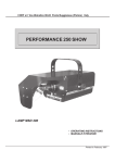
1
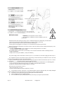
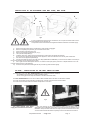
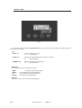
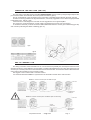
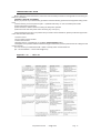
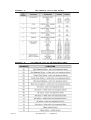
COEF srl.
Via Albinatico, 80-82
51019 Ponte Buggianese (PT)
ITALY
Sirio 1800DV / 2500DV
Graphic & pagination PC CAD & VIDEO
www.coef.it / www.coef.net
•
Code 02B012 - Sirio 1800 DV
•
Code 02B013 - Sirio 2500 DV
• OPERATING INSTRUCTIONS
Revision 1
INTRODUCTION
Thank you for using the Sirio 1800DV/2500DV !
The Sirio 1800DV/2500DV projects, thanks to an extremely efficient optic system (international patent n. WO99/40361), a
powerful light beam which can create numberless color shades. Its performances, in terms of luminousity and lighted surfaces, can
reach incredible levels.
The Sirio 1800DV/2500DV comes in two versions:
• Cod. 02B012 Sirio 1800DV for MHD 1200W discharge lamp
• Cod. 02B013 Sirio 2500DV for MHD 2500W discharge lamp or HMD 2500W discharge lamp
The Sirio 1800DV/2500DV can work in automatic mode or in synchro mode, otherwise may be controlled by 8 bit DMX controllers. The input protocol is the DMX 512. To drive the Sirio 1800DV/2500DV we suggest to use our controller MasterShow 512.
To make the most of its possibilites and for a correct functioning of this unit in the years to come, we suggest you to read
carefully this manual before connecting or putting the spot into use. By doing so you will gain experience with its commands and
connections and you will be easily able to use it.
ATTENTION: carefully read the directions of this manual. Exclusively follow the safety rules in force and do not carry
out assembly and/or maintenance operations without taking all precautions as indicated in the different sections or
without the necessary specialization.
This manual must always accompany the equipment, therefore it must be available and readable at any moment if
necessary. Also in case of sale, rent, change of place and/or ownership, these documents shall be enclosed with the
relative equipment.
ADVICES FOR A CORRECT INSTALLATION
This equipment is destined to an exclusively Professional use.
READ ALL CAUTIONS AND WARNINGS PRIOR TO OPERATE THIS EQUIPMENT.Instruction to prevent injury or damage
due to electric shock, fire, mechanical hazards and UV radiation hazards.
• PROTECTION AGAINTS FIRE
1) This equipment is designed for use with the following lamps only: MSD 1200W MSR 1800W.
DO NOT USE ANY OTHER TYPE LAMP!
2) Maintain minimum distance of 0.5 meter from walls or any other type flammable surfaces.
3) Maintain minimum distance to lighted objects of 5.0 meter.
4) Replace fuses only with the specified type and rating.
5) Do not install the spot close to heat sources. Do not lay the connection cable on the spot when it is warm.
• PROTECTION AGAINST ELECTRIC SHOCK
1) This equipment must be earthed.
2) Class I equipment. The power supply cord includes a protective earthing conductor as part of the cord.
3) For connection to the supply mains proceed as pict.1 page 3. The equipment must be connected to branch circuit having a
circuit- breacker (Code 02B012 In=16A Id=0.03A 230VAC) (Code 02B013 In=32A Id=0.03A 230VAC).
4) Disconnect power before lamp’s replacement or servicing (service personnel).
• PROTECTION AGAINST MECHANICAL HAZARDS
1) Use secondary safety chain when fixing this equipment.
2) Hot lamp explosion hazard. Do not open the equipment for 300 seconds after switching off.
3) Equipment surface may reach temperature up to 100°C. Allow about five minutes before handling.
4) Replace the lamp if it is damaged or thermally deformed.
• PROTECTION AGAINST UV RADIATION HAZARDS
1) Do not start on this equipment without lamp enclosure or if the protection screens, or ultraviolets screens are damaged.
2) The protection screens, the lenses, or the ultraviolet filters must be replaced if they are visibly damaged and their effectiveness has been reduced, for example, by cracks or deep scratches.
3) Do not look directly at the lamp while lamp is on.
Declaration of CE conformity
COEF srl. Via Albinatico, 80-82 / 51019 Ponte Buggianese (Pistoia) ITALY
Declare that the product Sirio 1800/2500DV is in conformity with 89/336 EEC-EMC directive and
with the actual required safety standars in accordance with LVD 73/23 EEC
Pag. 2
http://www.coef.it
-
[email protected]
DANGER SIGNAL: Generic dager signal and electric shock danger signal.
GENERAL WARRANTY CONDITIONS
•
•
•
•
•
•
•
•
The guarantee is valid for a period of 12 months from the date of purchase of the equipment.
The guarantee is not valid in case a wrong voltage or frequency is selected.
The parts which are proved to have manufacturing defects are also covered by the guarantee.
The external parts of the equipment, its removable elements and lamps are excluded from the guarantee; for these
parts we recommend to follow the directions supplied by their manufacturers.
The guarantee is not valid in case of tampering or repairs carried out by non-authorized personnel.
The replacement of the equipment during the validity of the guarantee is not provided for.
The transport freights from and to the manufacturer for repairs under guarantee are at Customer’s charge.
When applying for the repair, always mention the serial number and the model of the equipment.
PACKING CONTENTS
Carefully check the contents of the packaging and the completeness of the components. If any of the parts listed hereunder is
missing, please contact your Dealer immediately:
•
•
•
•
•
Sirio 1800DV/2500DV complet unit
This user manual
Termination resistor
1 connector POWER
2 plane reflectors “C”
PROTECT NATURE.
DO NOT DISPOSE OF THE PACKAGING IN THE ENVIRONMENT.
CAREFULLY KEEP THE BOX AND THE COMPONENTS OF THE PACKAGING FOR ANY DISPLACEMENT
OR RE-SHIPMENT OF THE EQUIPMENT.
Do not leave the packaging elements (polystyrene, nylon, metal parts, etc.) unattended.
TECHNICAL NOTES
Sirio 1800DV discharge lamp 1800W
•LAMP: discharge lamp MHD 1800W, Burning position: Horizontal (+/- 15°)
•COLORS: CYM color mixing continuously variable (256 steps)
•DIMMER: 0-100% continuously variable (256 steps)
•POWER INPUT: Rated voltage: 230Vac 50Hz; 230Vac 60Hz,
On request: 208Vac 60Hz; 200Vac 50Hz
Rated power: 2200 VA, Rated current: 10A (230Vac)
Sirio 2500DV discharge lamp 2500W
•LAMP: discharge lamp MSR 1800W , Burning position: Horizontal (+/- 15°)
•COLORS: CYM color mixing continuously variable (256 steps)
•DIMMER: 0-100% continuously variable (256 steps)
•POWER INPUT: Rated voltage: 230Vac 50Hz; 230Vac 60Hz,
On request: 208Vac 60Hz; 200Vac 50Hz
Rated power: 3000 VA, Rated current: 14A (230Vac)
http://www.coef.net - [email protected]
Pag. 3
INPUT CONNECTOR
FOR 1800W
CONNETTORE 3 POLI PER L’INGRESSO
RETE ALIMENTAZIONE
INPUT CONNECTOR
FOR 2500W High Power
BEFORE USING
fig.1
WARNING: The equipment must be earthed.
IP 54 grade: the equipment must be installed on the horizontal plane.
Read all cautions and warnings to page 1 prior to install this equipment. Particularly, read the follow:
1) Disconnect power before lamp’s replacement or servicing (service personnel)
2) Do not open the lamp cover for 300 seconds after switching off
3) Wear gloves and goggles to re-lamping or to work inside the unit (service personnel)
Before connecting the equipment to the power system: make sure that the mains voltage and frequency correspond to rated values.
• The Sirio 1800DV/2500DV can be equipped for a mains voltage 230VAC, 50 or 60Hz
on request: 208Vac, 60Hz; 200Vac, 50Hz
For a power supply of 100V-120V it is necessary to use one auto transformer with the following features:
• Output voltage 230V
• Output current 15A (Cod. 02B012) - 20A (Cod. 02B013)
The power supply cords construction is shown in pict.1. For connection to the mains supply proceed as pict.1.
The equipment must be connected to branch circuit having a circuit-breacker (Cod. 02B012 In=16A • Id=0.03A
230VAC) or (Cod. 02B013 In=32A • Id=0.03A 230VAC).
a) Do not install the spot close to the heat sources. Observe minimum distance between the spots of 1.5 meters.
Do not lay the
connection cable on the spot when it is warm.
b) This unit must be positioned as to allow its ventilation. Be careful not to acclude the in-out ventilating grilles.
c) The unit must be positioned at least 50cm. from walls or other flammable surfaces.
d) Observe minimum distance to lighted objects of 5 meters.
External surface temperature Ta 35°C:
• After 5 minutes work; Tc=75°C.
• Once the thermic balance has been obtained; Tc=100°C.
4)
The protection screens, the lenses, or the ultraviolet filters must be replaced if they are visibly damaged
and their effectiveness has been reduced, for example, by cracks or deep scratches.
5)
The lamp must be replaced if it has been damaged or thermally deformed.
6)
Clean regularly the in-out ventilating grilles.
7)
Do not handle the spot by taking it by the head, but always by using the special handles.
Pag. 4
http://www.coef.it
-
[email protected]
INSTALLATION OF THE DISCHARGE LAMP MSD 1200W, MSR 1800W
E
C
A
C1
G
D
C
fig.2
In case of replacement of the lamp or maintenance, do not open the fixture unless 5 minutes have passed from the switching off.
This operation has to be done when the apparatus is disconnected from the mains supply.
1)
2)
3)
4)
5)
6)
Disconnect power before lamp’ s replacement. Wear gloves and goggles.
Remove completely the pommels (A) on the base of the head
Open the base of the lamp room (G)
Remove the two lateral reflectors (C1) or (C)
Lift up the two lampholder (D)
Install the new lamp. Taking care that protuberance of the bulb is set towards the reflector
Do not touch the quarz bulb with fingers. If this happenes, clean the bulb before use with dry cloth and alcohol.
7)
Put down the two upper lampholders (D)
8)
Connect the cables (E) to the two ends of the lamp (MHD1800 or MHD2500) or connect the two cables of the lamp to
the two red insulators on the rear panel of the head.
9)
Put in again the two lateral plane reflectors. To obtain a wider optic (beam) use the C1 shaped reflectors. For a narrow optic (beam) use the C flat reflectors.
10) Close the rear panel and install again the two pommels (A) and hold them tightly.
IP RATE - INSTALLATION OF THE DUST PROOF FILTERS
The declared IP rate of the Sirio 1800DV/2500DV comes supported at these conditions:
• the installation of the fixture on a wide and stable surface
• the air cooling input and output are located on the base of the side-shell,
The Sirio 1800DV/2500DV has a IP rate 44 without filters installed and an IP RATE 54 with filters installed.
You must use the filters in critical working conditions and, normally, when the fixture works outdoor.
You must remove the filters when the ambient temperature is over 35°C.
fig.3
You must operate with power
supply disconnected from the fixture.
You must remove the two side protective shells. The two filters must be
assembled on the bulkheads at the bottom of the side brackets.Pay attention to the
installation: dust proof filters must stick correctly to prevent the entrance of the dust.
You must control that the two filters completely cover the overall of the air entrance.
http://www.coef.net - [email protected]
Pag. 5
CONTROL PANEL
fig.4
On the control panel of the Sirio 1800DV/2500DV (pict.4) you can find, besides the display, the leds and the buttons to use to set the spot.
LED
• “DMX” led
flashing: DMX input present
off:
no DMX input
• ”LAMP” led
flashing: the lamp switching off is remotely controlled
off:
lamp switched on
• ”DIMMER” led
flashing: the lamp is 33% dimmered
off:
lamp switched on
BUTTONS
Four buttons are used to programme the spot:
• MENU
• DOWN
• UP
• ENTER
to select the programming options
to go backward in the selected options
to go forward in the selected options
to confirm the selected options
DISPLAY
Shows the various menus and the selected options.
Pag. 6
http://www.coef.it
-
[email protected]
SUMMARY OF THE PROGRAMMING FUNCTIONS OF THE Sirio 1800DV/2500DV
About twenty seconds after the switching on, the number of the software version will be shown on the display in
“X_00” format. Afterwards the first of the nine available menus will appear:
Addr
Mode
LHrS
FHrS
nChn
FOCU
teSt
FLIP
rSEt
to assign the DMX-512 address
DMX512 mode, master with pre-set selection, slave
lamp working hours
fixture total working hours
channels number
parabole position
auto-test
display inversion
reset of the spot
To select any of the given options, press the MENU button up to when the required one is shown.
Addr (Address)
To visualise the DMX address press ENTER.
To modify the address press Down and Up buttons and, once the required address has been selected, press
and keep ENTER pressed up to when the display stops flashing (it flashes to indicate that the selected option is different from the pre-set one). To go back to the options without making any change, press the MENU button.
Mode (Mode)
To visualise this mode press ENTER.
Use Down and Up buttons to change the mode and, once the required one has been selected, press and keep
ENTER pressed up to when the display stops flashing (it flashes to indicate that the selected option is different from
the pre-set one). The available options are: no (normal) for the functioning in DMX reception; Pr01…Pr27 (pre-set
01…27) for the master functioning with the respective game, SL (slave) for the functioning as slave. To go back to
the options without any change, press the MENU button.
LHrS (Lamp Hours)
To visualise the number of working hours of lamp press ENTER.
The maximum countable number of hours is 3000. Exceeding this number, the display will show gr3t (greater
than 3 thousands). To reset the counter press simultaneously buttons Down and UP: the display will show CLLH
(clear lamp hours). To go back to the options without making any change, press the MENU button.
FHrS (Fixture hours)
To visualise the number of working hours of fixture press ENTER. The maximum countable number of hours is
3000. Exceeding this number, the display will show gr3t (greater than 3 thousands). To reset the counter press simultaneously buttons Down and UP. A control of the memory will be run and all the default settings will be stored: the
display will then show Init. If the memory is damaged, the display will show the message FAIL. To go back to the options without making any change, press the MENU button.
http://www.coef.net - [email protected]
Pag. 7
nChn (Number of Channel)
To visualise the number of channel press ENTER.
Use Down and Up buttons to change the channel and, once the required one has been selected, press and keep
ENTER pressed up to when the display stops flashing (it flashes to indicate that the selected option is different from
the pre-set one). It is possible to set 6 channels or 7 channels ( remote reset and remote lamp switch off ). To go back
to the options without making any change, press the MENU button.
teSt (Autotest)
To insert the auto-test press ENTER and keep it pressed up to when the display shows the flashing message ton (test on). To take off the auto-test press the MENU button. To go back to the options without making any change,
press the MENU button.
FLIP (Display overturning)
The display visualisation can be standard or overturned: by pressing the ENTER button the two modes will be alternatively visible. The selected one will be immediately stored in the spot setting.
To go back to the options without making any change, press the MENU button.
rSEt (Reset)
To run the complete reset press ENTER and keep it pressed up to when the display shows the flashing message
r-on (reset on). Once the reset procedure has been completed the spot will go back to the normal setting. To go back
to the options without making any change, press the MENU button.
DRIVING THE Sirio 1800DV/2500DV WITH A DMX REMOTE CONTROLLER
• Select the requested DMX starting address by operating on the Addr option
• Select the requested number of channel with NChn option
• Connect the DMX signal between the fixture and the controller
• Check that the DMX led is flasing. (DMX signal present)
• If there is no signal, you must manually reset by operating on the RESET option%
6/7 CHANNELS MODE SELECTION
Press the MENU button on the control panel up to when the option nChn is shown on the display, select it by
pressing ENTER and the set indication will appear (6 or 7 channels). If you want to activate channel 7 you must set 6
channels on the display. Pass through the numbers by pressing the buttons UP and DOWN: once you have set the
required number, store it by pressing the ENTER button and keep it pressed up to when the display stops flashing
(the flashing shows that the selected option is different from the one previously stored). To exit from the selected option without making any change press the MENU button.
Here below is shown the complete list of the functions of the Sirio 1800DV/2500DV.
The complete list of the DMX values can be found in appendix “A”
7 CHANNELS
CH 1=
CH 2=
CH 3=
CH 4=
CH 5=
CH 6=
CH 7=
Pag. 8
6 CHANNELS
Speed
Cyan
Yellow
Magenta
Dimmer
Basic colors+rainbow
Reset/Lamp Off
CH 1=
CH 2=
CH 3=
CH 4=
CH 5=
CH 6=
http://www.coef.it
-
Speed
Cyan
Yellow
Magenta
Dimmer
Basic colors+rainbow
[email protected]
CONNECTION THE DATA LINK (DMX 512)
The connection of the DMX signal to the Sirio 1800DV/2500DV must be made by using the signal input XLR 5
pin connectors which are located on the control panel of the fixture. (pict.5)
The pin nomenclature of the connectors for the connection to the DMX signal is listed in the table. (pict.5a)
In order to avoid any problem in the signal transmission, it is warmly suggested to use a cable for high speed data
transmission (sect. 2x0.25 + gnd).
If the lines have a total length over 150-200 mts it is suggested to use a signal amplifier.
The usage of a normal microphonic or audio cable is suggested only for lines max 100 mts long.
To ensure the IP54 rate you must connect the DMX cable inside the base. Use the given cables fixing (pict. 5b)
and connect by following the cables numbering (pict. 5c).
fig.5c
fig.5
fig.5a
fig.5b
DMX 512 TERMINAL LINE
The wrong connection of the terminal line or its non-connection are probably the most frequent reasons for the
defective functioning of the DMX line. The terminator is a resistor fitted between the two “data” lines (pins 2 and 3 of
an XLR 5 pin connector) at the end of the cable furthest from the transmitter. The terminator resistor should have the
same value as the impedance of the connection cable.
We suggest to use a terminal with a 100 Ohm resistor.
It is recommanded that all DMX 512 systems have the termination resistor at the and of the line.
EXAMPLE 1: connection controller-spot with 1 DMX 512 output
LAST SPOT
SPOT
SPOT
SPOT
CONTROLLER DMX
TERMINATION
RESISTOR
EXAMPLE 2: connection controller-spot to one DMX 512 output over 150mts long
LAST SPOT
SIGNAL
AMPLIFIER
SPOT
CONTROLLER DMX
TERMINATION
RESISTOR
http://www.coef.net - [email protected]
Pag. 9
USE OF THE Sirio 1800DV/2500DV IN AUTO-MODE
MASTER
A short list of the games can be found in appendix “B”.
Press the MENU button on the control panel up to when the option MODE (pict. 7) is shown on the display, select
it by pressing ENTER and the set indication will appear (no...SL). Use Down and Up buttons to change the mode
and, once the required one has been selected, press and keep ENTER pressed up to when the display stops flashing (it flashes to indicate that the selected option is different from the pre-set one). The available options are: no
(normal) for the functioning in DMX reception; Pr01…Pr27 (pre-set 01…27) for the master functioning with the respective game, SL (slave) for the functioning as slave.
To go back to the options without any change, press the MENU button.
Mode no
use of the Sirio 1800DV/2500DV in DMX-512
Pr1..Pr27
master functioning with execution of the 27 stored programme
SL
use of the Sirio 1800DV/2500DV in SLAVE MODE
EXAMPLE OF CONNECTION AND SETTING OF 4 “SIRIO 1800DV/2500DV” IN SYNCHRO - MODE
MASTER
SLAVE
SLAVE
SLAVE
WARNING: the cables are the same as the DMX standard cable
EXAMPLE OF CONNECTION AND SETTING OF 4 “SIRIO 1800DV/2500DV” IN INDIPENDENT AUTO - MODE
MASTER
Pag. 10
MASTER
http://www.coef.it
MASTER
-
[email protected]
MASTER
TROUBLESHOOTING GUIDE
Before calling for technical assistance, follow the recommended procedures in this appendix to solve many problems on your fixture.
CAUTION! • BEFORE YUO BEGIN:
Before you perform any troubleshooting procedures read the following personnel and equipment safety precautions:
1) Refer servicing to service personnel (Q.T.= qualified technician); no user serviceable parts inside
2) Wear hand and eye protection
3) Wait at least five minutes before accessing the lamp after operation
4) Disconnect the unit from power before removing any cover (Q.T.)
If the procedures do not solve your problem and you need to call for assistance, please provide the support technician with the follow information:
• Customer name
• Phone number and fax number
• Fixture serial number
• Message that are you displayed on your Sirio 1800DV/2500DV display
• Description of the problem and the troubleshooting procedures that you have performed so far to diagnose and
resolve the fault.
You can contact your authorized COEF dealer or directly COEF Technical Service.
(fax. +39.0572.636535 - e-mail: [email protected])
Appendix “C” - Table A1
http://www.coef.net - [email protected]
Pag. 11
DATA LINK (DMX 512) TROUBLESHOOTING
Appendix “C” - Table A2
Pag. 12
http://www.coef.it
-
[email protected]
MAIN BOARD CONNECTIONS
U11 VIPER SWITCHING
C65
U5 U6 U7 U8 U9 L6219
MOTOR DRIVER
U4 MICRO SLAVE MOTOR
CCSLAVEXX
LED +5V
LED +5V OPTO DMX
U3 MICRO MASTER
MOTOR CC3DRVXX
U13 78M05
OPTO DMX
TO DISPLAY
PCB PAN IP
LED
320VDC
MAIN POWER
INPUT
TO CC250
MOT3
TO HEAD FAN
MOT2
DIMMER
LED +28V
TO PCB
CC250
D1 OFF LINE BRIDGE
RECTIFIER
MOT1
FOCUS
TO BASE FAN
VRI VARISTOR 275V
(OVERVOLTAGE PROTECTION)
MOT4
YELLOW
U12 7805
+5V
MOT5
CYAN
TO LAMP BOX, CYM BOX
SAFETY SWITCH
D3
U10 MICRO PWM
FAN CONTROLLER
TO HEAD THERMAL
SENSOR AND SWITCH
• POWER SUPPLY +30V Led On, +5V Led, +320V Led, +5V DMX Led
• DMX signal
Led flashing:
the DMX signal is operating on the board
Led off:
check the U1 (6N137) and the DMX connecting cable (from PCB PAN IP)
• STEPPER MOTOR channel not working: (i.e. YELLOW):
1)
Switch off the fixture and disconnect the YELLOW and CYAN cables
2)
Connect the YELLOW cable on the CYAN connector
3)
Switch on the fixture:
3a)
If the YELLOW motor works normally it is necessary to replace the U6 (L6219)
3b)
If the motor is still not working check with extreme attention the motor and the interconnecting circuits (cables and connectors). To
check the cables and the motors you can measure the resistance as follows: between PIN 1 and PIN21 (on IC U6)r=~18ohm; between PIN 2
and PIN5 (on IC U6) r=~18ohm
• If the led +5V OPTODMX is off:
1)
Disconnect TO DISPLAY PCB PAN IP connector; if the led is on check PCB PAN IP
2)
Check U13 (78M05), L3, D6
1)
2)
1)
1a)
1b)
1c)
1d)
2)
2a)
2b)
2c)
2d)
• If the led +5V is off:
Disconnect TO DISPLAY PCB PAN IP connector; if the led is on check PCB PAN IP
Check D4, L2, U12
•If the led +28V is off:
Check if the led +320V is on, if it is ok:
Check if U11 is in thermal drift (ATTENTION on the heat dissipator there is dangerous tension!!!!)
Check if U5, U6, U7, U8, U9 are in short-circuit. Switch off the fixture. Remove all the chips from the socket.
Switch on the fixture: if the led is on, insert the chips one by one in the sockets to find out which is in short-circuit.
Check D3
If all the operations described above have not given any positive result, change U11
If the led +28V is off together with the led +320V
Check the MAIN POWER INPUT where you can measure the working voltage
Check the main fuse, if it is blown check VR1 (normally it has a resistance = ¥). If it is in short circuit you must change it.
Check D1 (Bridge Rectifier), if it is ok check C65.
If the fuse is still blown, change U11
http://www.coef.net - [email protected]
Pag. 13
APPENDIX -A-
APPENDIX -B-
Pag. 14
THE COMPLETE LIST OF DMX VALUES
THE COMPLETE LIST OF THE AVAILABLE GAMES
http://www.coef.it
-
[email protected]