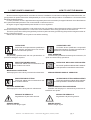
1
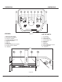
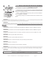
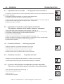
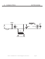
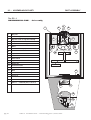
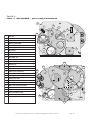
COEF srl Via Albinatico 80-82 Ponte Buggianese (Pistoia) Italy
PERFORMANCE 250 SHOW
LAMP MSD 200
• OPERATING INSTRUCTIONS
• MANUALE ISTRUZIONI
Printed in February 1997
DIMENSIONI
DIMENSIONS
1
2
5
4
3
4
7
6
1
DMX 512
POWER
CAUTION:
OFF
IN
OUT
DO NOT OPEN THE LAMP COVER BEFORE
HAVING DISCONNECTED THE POWER
ON
200-240 V.AC
FUSE
50Hz
T
60Hz
PIN1: GND
PIN2: SIGNALPIN3: SIGNAL+
REPLACE THE FUSE WITH SAME TYPE AND RATING
PISTOIA ITALY
TEL. ++39 572 636536 a.r.
CHECK
S/N
390
Figure 21
LEGENDA
LIST OF PARTS
1 - Manopole bloccaggio
2 - Interruttore accensione
3 - Presa con fusibile
4 - Pomelli sportello lampada
5 - Sportello lampada
6 - DMX IN
7 - DMX OUT
8 - Pomelli regolazione lampada
9 - Pomello blocco obiettivo
10 - Obiettivo
1 - Lock knobs
2 - Power switch
3 - Outlet with fuse
4 - Screws lamp door
5 - Lamp door
6 - DMX IN
7 - DMX OUT
8 - Lamp adjustment screws
9 - Screw objective
10 - Objective
590
1
9
10
214
8
Figure 20
COEF srl Via Albinatico 80-82 51019 Ponte Buggianese (Pistoia) Italy - tel +39-572-636537 a.r Fax 636535
®
COEF srl. Via Albinatico, 80-82 Ponte Buggianese 51019 ( Pistoia ) ITALY
tel. (+39) 0572-636536 r.a.
Fax (+39) 0572 - 636535
Tutti i diritti di riproduzione, diffusione del presente manuale
sono riservati all COEF srl.
Le descrizioni ed illustrazioni fornite nella presente pubblicazione non sono impegnative.
La COEF srl. si riserva il diritto di apportare in qualsiasi momento tutte le modifiche che riterrà opportune.
Il presente manuale non può essere ceduto in visione a terzi
senza specifica autorizzazione scritta dalla COEF srl.
All rights for reproduction of this catalogue are reserved for
COEF srl.
Descriptions and illustrations are not binding.
COEF srl. reserves the right to make all necessary modifications at any time.
This manual can not be inspected by third party, without written autorization by COEF srl.
Les droits de reproduction de ce catalogue sont entiérement
réservés à la Société COEF srl.
Les descriptions et les illustrations fournies dans ce manuel
n’engagent acunement notre Société.
COEF srl. se réserve le droit d’apporter, à tout moment, les
modifications qu’elle jugera utiles.
Ce manuel ne peut être remis à des tiers sans l’autorisation
préalable de la Société COEF srl.
Alle Rechte vorbehalten. Nachdruck verboten.
Die in diesem Handbuch enthaltenen Beschreibungen und
Abbildungen sind nicht verbindilich.
Die Firma COEF srl. behält sich das Recht auf Änderungen
zu jedem Zeitpunkt vor.
Diese Bedienungsanleitung darf ohne schriftliche Genehmigung der Firma COEF srl. dritten Personen nicht zugänglich
gemacht werden.
pag. 3
COEF srl. Via Albinatico 80-82 - 51019 Ponte Buggianese ( Pistoia ) ITALY
INDICE
INDEX
1.0 COME USARE IL MANUALE - HOW TO USE THE MANUAL
.............
2.0 INSTALLAZIONE - INSTALLATION
......................................................
2.1
Montaggio
o
sostituzione
specchio........................................................................................
Mirror mounting or replace ...................................................................................................
2.2
Montaggio
o
sostituzione
lampada
........................................................................................
Lamp mounting and re-lamping ...........................................................................................
2.3
Montaggio
dell’apparecchiatura
............................................................................................
Machine mounting ................................................................................................................
2.4
Dettaglio
componenti
staffa
di
fissaggio
................................................................................
Bracket components’ details ................................................................................................
2.5
Consigli
per
una
corretta
installazione
...................................................................................
Advices for a correct installation ..........................................................................................
3.0 COLLEGAMENTI - CONNECTIONS
.....................................................
3.1
Collegamento
alimentazione
rete
.........................................................................................
Power supply connection .....................................................................................................
3.2
Collegamento
DMX
512
........................................................................................................
DMX 512 connection ...........................................................................................................
pag. 5
pag. 6
pag. 6
pag. 6
pag. 7
pag. 7
pag. 7
pag. 7
pag. 8
pag. 8
pag. 8
pag. 8
pag. 9
pag. 9
pag. 9
pag. 9
pag. 9
pag. 10
pag. 10
pag. 10
pag. 10
pag. 10
pag. 11
pag. 11
4.0 POSIZIONAMENTO E REGOLAZIONI - POSITIONING AND
REGULATIONS
pag. 11
pag. 11
4.1
Posizionamento
...................................................................................................................
Positioning ...........................................................................................................................
pag. 12
pag. 13
4.2
Regolazione
del
fuoco
..........................................................................................................
Focus Adjustment ................................................................................................................
pag. 14
COEF srl Via Albinatico 80-82 - 51019 Ponte Buggianese ( Pistoia ) ITALY
pag. 4
7.0 MANUTENZIONE - MAINTENANCE
...................................................
pag. 16
7.1
Manutenzione
ordinaria
........................................................................................................
Ordinary maintenance .........................................................................................................
pag. 16
pag. 16
pag. 16
pag. 16
7.2
Manutenzione
straordinaria
.........
........................................................................................
Extraordinary maintenance .................................................................................................
pag. 18
pag. 18
7.3
Manutenzione
elettrica
/
elettronica.......................................................................................
Electronic maintenance.........................................................................................................
pag. 19
pag. 19
pag. 19
8.0 PROBLEMI - TROUBLESHOOTING
.....................................................
pag. 19
pag. 19
8.1
Il
proiettore
non
si
accende
....................................................................................................
The projector doesn’t switch on.............................................................................................
8.2
Il
proiettore
si
accende
ma
non
risponde
ai
comandi...............................................................
The projector switch on but doesn’t answer to commands......................................................
8.3
Proiezione
difettosa
..............................................................................................................
Defecting projection .............................................................................................................
pag. 19
pag. 19
pag. 19
pag. 19
pag. 19
pag. 19
pag. 20
8.4
Proiezione
con
alone
............................................................................................................
Projection with halo ..............................................................................................................
pag. 20
8.5
Il
colore
o
altri
effetti
non
corrispondono
al
valore
impostato
...................................................
The color or other effects doesn’t coincide to the selected value ..........................................
pag. 22
9.0 ALLEGATI - ENCLOSURES
................................................................
Dichiarazione di conformità - Conformity declaration ..............................................................
Schema elettrico - Electric diagram..........................................................................................
Assemblaggio parti - Part assembly..........................................................................................
Dimensioni
..........................................................................................................
pag. 5
Dimensions
COEF srl. Via Albinatico 80-82 - 51019 Ponte Buggianese ( Pistoia ) ITALY
pag. 21
pag. 24
1 - COME USARE IL MANUALE
HOW TO USE THE MANUAL
Questo manuale è organizzato in modo tale che l’utente, l’installatore o il manutentore dell’apparecchiatura descritta, venga supportato da quelle informazioni indispensabili per un uso corretto delle procedure di installazione e di funzionamento
dell’apparecchiatura stessa.
Le varie procedure verranno appositamente segnalate (dove sarà necessario) da segnali indicatori che evidenzieranno
sia le pericolosità dell’operazione che le necessità di un intervento tecnico.
Di seguito vengono rappresentati questi simboli con il loro significato.
This manual has been organized in order support the user, the installer or the maintenance operator of the described unit
with those necessary informations for a correct use of the installation and working procedures of the same unit.
The various procedures will be just signalled by indicators (when necessary) evidencing the operation dangers and the necessity of technical support.
Please find here below a list of symbols and relative meaning:
OPERATORE
Personale non espressamente qualificato in
grado di eseguire operazioni dove non è richiesta una conoscenza specifica.
OPERATORE COEF
Personale tecnico qualificato e responsabilizzato dal costruttore, per tutte le operazioni di riparazione o interventi straordinari.
OPERATOR
COEF OPERATOR
Not particulary qualified staff, that can operate when no
Technical staff, qualified and trained by the constructor, for
specific knowledge is required.
repair and extraordinary operations.
MANUTENTORI MECCANICI
Personale addetto alla manutenzione ordinaria di natura meccanica.
MECHANICAL OPERATORS
Staff employed in the ordinary mechanical maintenance.
MANUTENTORI ELETTRICI
Personale addetto alla manutenzione ordinaria di natura elettrica.
ELECTRIC OPERATORS
Staff employed in the ordinary electric maintenance.
SEGNALE DI PERICOLO
Segnalazione di parti sotto tensione.
DANGER SIGNAL
Electric shock danger signal.
TI
OPERATORI MECCANICI SPECIALIZZA-
Personale qualificato addetto alla installazione o alle riparazioni straordinarie autorizzate.
SPECIALIZED MECHANICAL OPERATOR
OPERATORI ELETTRICI SPECIALIZZATI
Personale qualificato addetto alla installazione o alle riparazioni straordinarie autorizzate.
SPECIALIZED ELECTRIC OPERATORS
Qualified staff employed in extraordinary authorized installations and repairs.
SEGNALE DI PERICOLO
Segnalazione di pericolo generico.
DANGER SIGNAL
Generic danger signal.
COEF srl Via Albinatico 80-82 - 51019 Ponte Buggianese ( Pistoia ) ITALY
pag. 6
2 - INSTALLAZIONE
INSTALLATION
Il Fabbricante si ritiene sollevato da eventuali responsabilità in caso di:
•
•
•
•
•
•
•
•
•
uso improprio della apparecchiatura o da parte di personale non addestrato
uso contrario alla direttive in materia di sicurezza sul lavoro
installazione non corretta
difetti di alimentazione
gravi carenze nella manutenzione prevista
modifiche o interventi non autorizzati
utilizzo di ricambi non originali o non specifici per il modello
inosservanza totale o parziale delle istruzioni
eventi eccezionali
The constructor is not to be considered responsible in the case of:
•
•
•
•
•
•
•
•
•
improper use of the unit or use by not trained staff
use in contrast with the directions on work safety
wrong installation
defective power supply
serious lacks in the necessary maintenance
unauthorized modifications and interventions
use of spare parts that are not original or not specific for the unit
total or partial inobservance of instructions
unusual events.
2.1 - Montaggio o sostituzione specchio - Mirror mounting or replacement
Rimuovere con cura la corda elastica che tiene bloccato il motore del gruppo scansione.
In caso di sostituzione dello specchio C, svitare le due viti B e rimuovere lo
specchio rotto o da sostituire. Procedere in senso inverso applicando il ricambio con il supporto già montato in fabbrica sul motore A (vedi Fig. 2 e Fig. 3).
ATTENZIONE! Lo specchio è molto delicato e quindi deve essere maneggiato con cura.
Figure 1
Remove the elastic band that’s blocking the motor of scansion group. For
the mirror replacement (C), screw the two screws (B) and remove the broken
mirror. Install the new spare part (its support is already mounted by the factory)
on the motor A, carefully closing, using an hexagonal screwdriver (see fig. 2
and Fig. 3).
WARNING! The mirror is very delicate, so you must handle it with great
care.
Figure 2
pag. 7
COEF srl. Via Albinatico 80-82 - 51019 Ponte Buggianese ( Pistoia ) ITALY
2.2 - Montaggio o sostituzione lampada - Lamp mounting and replacing
ATTENZIONE: disconnettere l’alimentazione al proiettore prima dell’operazione
WARNING: switch off the projector before operating.
Svitare le due viti (part. B fig. 4) e rimuovere il coperchio rotondo che supporta
la lampada. Inserire la lampada (HSD 200) nello zoccolo. Inserire delicatamente
la lampada nell’alloggio del proiettore guidandola con il coperchio rotondo (fig.5).
Fare attenzione che i fili del portalampada ritornino correttamente all’interno
del proiettore.
Bloccare il coperchio riavvitando le viti (part. B fig.4).
Figure 3
Screw the two screws off (part. B fig.4) and remove the round cover that’s
supporting the lampholder. Insert the lamp (HSD 200) in the socket. Insert delicately the lamp in the projector support, driving it with the round cover (fig.5).
Pay attention: the lampholder’s wires must correctly reenter in the projector. Block the cover screwing the screws up ( part. B fig.4).
Figure 4
2.3 - Montaggio dell’apparecchiatura - Machine installation
Per il fissaggio del PERFORMANCE 200 SHOW è indispensabile, quando l’installazione è prevista su di una
attrezzatura dI sostegno sollevata da terra, bloccare la staffa di fissaggio dell’apparecchio con una adeguata vite
con dado e controdado di misura non inferiore a M10X50, da inserire nel foro centrale predisposto sulla staffa di
fissaggio.
Per garantire una sicurezza essenziale e nel rispetto delle attuali norme di sicurezza per l’installazione delle
apparecchiature, consigliamo di installare una catena di sicurezza (o cavo d’acciaio) con moschettoni che collega il corpo
macchina del PERFORMANCE 200 SHOW alla struttura di ancoraggio.
ATTENZIONE: COEF non risponde di installazioni scorrette od effettuate senza il rispetto delle suddette indicazioni, e
quindi considerate pericolose.
To fix the PERFORMANCE 200 SHOW is necessary, when the installation has to be on a raised-from-the
ground support, to block the fixing bracket of the unit by means of a screw provided with nut and locknut measuring not less than M10X50, to insert in the central pre-arranged hole on the fixing bracket. To guarantee a necessary security and in respect of the actual safety rules about the units’ installation, we advise to install a security
chain (or a steel cable), provided with hooks, linking the body of the PERFORMANCE 200 SHOW to the fixing
structure .
ATTENTION: COEF is not responsible for installations not correctly made or made without respecting the above indications: those installations are considered dangerous..
COEF srl Via Albinatico 80-82 - 51019 Ponte Buggianese ( Pistoia ) ITALY
pag. 8
2.4 - Dettaglio componenti staffa -
Bracket components’ details
Figure 5
In caso di smontaggio della staffa di fissaggio del PERFORMANCE 200 SHOW, usare la Fig. 6 come riferimento per poter
rimontare correttamente la staffa con tutti i suoi componenti, senza pregiudicarne il funzionamento e la sicurezza.
When you need to disassemble the fixing bracket of the PERFORMANCE 200 SHOW, refer to Fig.6 to re-assemble correctly the bracket with all its components, without damaging its functionality and security.
2.5 - Consigli di corretta installazione - Advices for a correct installation
Per un corretto funzionamento dell’apparecchiatura rispettare le seguenti condizioni:
1)
Non installare il proiettore all’esterno dove è possibile l’influenza di agenti atmosferici dannosi al funzionamento
dell’apparecchiatura stessa (pioggia, vento, sole intenso ecc. ).
2) Non eseguire la pulizia del proiettore con getti di acqua o immersione in altri liquidi, ma attenersi scrupolosamente a
quanto indicato nel capitolo MANUTENZIONE.
3) Eseguire i collegamenti elettrici e la installazione / sostituzione della lampada in assenza di tensione di alimentazione
e con l’interruttore di accensione in posizione OFF.
4) Non manomettere in alcun modo le parti interne ed esterne del proiettore senza preventiva autorizzazione del fabbricante e senza che le modifiche vengano eseguite da personale qualificato.
5) Assicurarsi del corretto fissagio del proiettore alla struttura di sostegno come indicato al paragrafo 2.3.
The following conditions have to be respected for a correct operation:
1) Do not install the projector outside where the influence of atmospheric factors could damage the unit working (rain,
wind, intense heat etc.).
2) Do not clean the projector using water jets or immersion in different liquids. Scrupulously follow the indications given in
the chapter MAINTENANCE.
3) Make the electric connections and the installation / replacement of the lamp after having disconnected the power supply and after haved positioned the power switch to OFF.
4) Do not touch in any case the internal and external parts of the projector without previous authorization of the constructor and make modifications only by the intervention of qualified staff.
5) Make sure that the projector is correctly fixed on the support as indicated in par.2.3.
pag. 9
COEF srl. Via Albinatico 80-82 - 51019 Ponte Buggianese ( Pistoia ) ITALY
3 - COLLEGAMENTI
CONNECTIONS
3.1 - Collegamento alimentazione rete - Power supply connections
Alimentare il proiettore collegandolo come indicato in Fig. 7 con tensione e frequenza indicati sul retro del proiettore.
Supply the projector by connecting it as indicated in Fig. 7 with Voltage and Frequency as indicated on the rear of the projector.
CHECK
S/N
CHECK
S/N
CHECK
S/N
PHASE
GROUND
NEUTRAL
Figure 6
3.2 - Collegamento DMX 512 - DMX 512 connection
Collegare il proiettore e l’unità di controllo con un ottimo cavo schermato bipolare, corredato di spine e prese Cannon 3 Pin
XRL. Rispettare, secondo la serigrafia riportata sul pannello, gli ingressi e le uscite del segnale DMX 512.
Connect the projector to the control unit by means of a RG58 or RG59 coaxial cable supplied with 3 Pin XRL Cannon plugs
and connectors. Respect, according to the indications on the panel, the input and the output of the DMX 512 signal.
S/N
CHECK
S/N
CHECK
S/N
CHECK
FROM CONTROL UNIT
Figure 7
COEF srl Via Albinatico 80-82 - 51019 Ponte Buggianese ( Pistoia ) ITALY
pag. 10
4 - POSIZIONAMENTO E REGOLAZIONI
4.1 - Posizionamento
POSITIONING AND REGULATIONS
- Positioning
Per posizionare il proiettore occorre predisporre i canali come segue:
CANALE 1 - OTTURATORE
CANALE 2 - COLORE
CANALE 3 - GOBOS
CANALE 4 - ROT.GOBOS
CANALE 5 - EFFETTI
CANALE 6 - ROT. PRISMI
CANALE 7 - PAN / TILT
CANALE 8 - TILT / PAN
Aperto
Neutro
Nessuna figura
Nessuna rotazione
Neutro
Nessuna rotazione
Regolato al 50%
Regolato al 50%
Posizionare il proiettore ruotandolo sulla sua staffa di sostegno, quindi bloccarlo con le manopole (part.1 Pag. 23). La posizione del fascio luminoso corrisponderà al centro della Vostra scena.
The projector can be positioned by pre-arranging the channels in this way :
CHANNEL 1 - SHUTTER
CHANNEL 2 - COLORS
CHANNEL 3 - GOBOS
CHANNEL 4 - GOBOS ROT.
CHANNEL 5 - EFFECTS
CHANNEL 6 - PRISM ROT.
CHANNEL 7 - PAN / TILT
CHANNEL 8 - TILT / PAN
Open
White
No figure
No rotation
Neutral
No rotation
Regulated on 50%
Regulated on 50%
Position the projector by rotating it on its support bracket, then block it using the knobs 1 (part. 1 Pag. 23). The position of
the light beam will correspond to the centre of your scene.
4.2 - Regolazione del fuoco - Focus adjustment
Per regolare l’obiettivo occorre predisporre i canali come indicato al punto 4.1 ad eccezione di:
CANALE 3 - GOBOS
co.
Posizionato sulla figura desiderata
Allentare la vite 9 (Pag. 23) e muovere assialmente l’obiettivo 10 (Pag.23) fino a che l’immagine proiettata non risulti a fuo-
To adjust the focus you must pre-arrange the channels as indicated at par.4.1, except:
CHANNEL 3 - GOBOS
Has to be positioned on the desired figure
Loosen the screw 9 (Pag.23) and axially move the objective 10 (Pag.23) until the projected image is focused.
pag. 11
COEF srl. Via Albinatico 80-82 - 51019 Ponte Buggianese ( Pistoia ) ITALY
4.3 - Regolazione lampada
-
Lamp adjustment
La regolazione della lampada è indispensabile per ottenere un fascio luminoso uniforme e potente. Accendere il proiettore ed impostare i canali come specificato al paragrafo 4.1. Regolare i 3 pomelli A (Fig.9) fino a raggiungere la condizione ideale tra potenza del fascio ed omogeneità.
ATTENZIONE! La lampada è pre-regolata in fabbrica. Regolare solo finemente. Non portare i pomelli al punto
estremo inferiore o superiore.
Figure 8
Lamp adjustment is necessary to obtain a uniform and powerful light beam. Switch on the projector and set the channels
as specified in par. 4.1. Adjust the three screws A (Fig. 9) until you reach the ideal condition between power and homogeneity.
Warning! The lamp is pre-regulated by the factory. Only fine-adjustment. Don’t move the screws A up to upper or
lower extremities.
4.4 - Sostituzione gobos
-
Gobos sostitution
La ruota gobos del Performance 200 SHOW contiene sia gobos in acciaio che gobos dicroici. I due tipi di gobos risultano intercambiabili semplicemente rimuovendo l’anello elastico in acciaio dal suo alloggio.
Raccomandiamo di non sostituire un gobos in acciaio con uno dicroico e
viceversa, data la diversità dei supporti in bronzo dei gobos stessi.
Per la sostituzione rispettare le seguenti indicazioni:
Spessore per gobos in acciaio: 2/10 mm.
Spessore per gobos dicroici: min.1mm. / max. 1,2 mm.
The gobos wheel of Performance 200 SHOW, contains both steel gobos and glass/dichroic gobos. These two types of gobos are interchangeable by simply taking off the steel elastic ring from its place. Pay Attention: don’t replace a steel gobo with a
dichroic one and viceversa, because there is a difference in the gobos bronze support.
For the replacements, respect the following indications:
Thickness for steel gobos: 2/10 mm.
Thickness for dichroic gobos: min. 1mm. / max. 1,2mm.
COEF srl Via Albinatico 80-82 - 51019 Ponte Buggianese ( Pistoia ) ITALY
pag. 12
5 - CODIFICA E FUNZIONI SPECIALI
B
A
C
D
E
Nel pannello frontale del PERFORMANCE 200 SHOW troviamo una sezione
dedicata al settaggio del proiettore e alle funzioni accessorie.
Una chiara legenda permette di comprendere in modo intuitivo le operazioni
da compiere per le varie regolazioni e/o settaggi senza l’ausilio di un manuale, ma
in questa pagina potrete trovare una esposizione più chiara ed esauriente circa le
procedure di regolazione. Seguendo la Fig. 10 vediamo in dettaglio tutte le varie
possibilità offerte.
Tutte le operazioni si effettuano tramite i pulsanti C, D, E, indicati rispettivamente come SELECT e SEARCH.
Premendo C ripetitivamente selezioniamo la funzione desiderata indicata dal
display A.
Figure 9
FUNZIONE 1
Permette di assegnare il proiettore come n. macchina ( 1, 2, 3 ecc. ) tenendo conto del canale di partenza (settato con la
funzione 2) e del numero dei canali del proiettore. La ricerca avviene in modo ascendente con il pulsante E ed in modo discendente con il pulsante D.
FUNZIONE 2
Permette di assegnare il proiettore ad un determinato canale DMX di partenza, a seconda dell’apparecchiatura di controllo usata. Se desideriamo assegnare tutti i proiettori con questo sistema, è importante verificare che nella FUNZIONE 1 il
proiettore sia settato come macchina 001.
FUNZIONE 3
Scambia il senso di direzione del Canale PAN. Il display B indicherà Std per “Standard” o OPP per “Opposta”.
FUNZIONE 4
Scambia il senso di direzione del Canale TILT. Il display B indicherà Std per “Standard” o OPP per “Opposta”.
FUNZIONE 5
Commuta l’assegnazione del canale 7 al TILT e 8 al PAN o viceversa. Std = 7,PAN 8,TILT
FUNZIONE 6
Cambio colore con otturatore inserito. Std = Colore senza otturatore.
FUNZIONE 7
Cambio gobos con otturatore inserito. Std = Gobos senza otturatore.
FUNZIONE 8
Indica le ore di funzionamento della lampada. Resettare a 000 le ore lampada con uno dei due pulsanti D o E.
FUNZIONE 9
Indica le ore di funzionamento del proiettore.
FUNZIONE t
Viene eseguito un test per ogni canale del proiettore.
FUNZIONE d
Questa funzione dà la possibilità di spengere il display dopo due minuti dal momento in cui è stata inserita. Premendo un
pulsante ( C, D o E ) il display si riaccenderà permettendo modifiche sui settaggi del proiettore.
FUNZIONE h
Pedispone la macchina per la configurazione a 6 o 8 canali.
ATTENZIONE! Settare il proiettore attraverso la FUNZIONE h a seconda del pilotaggio a disposizione.
Es: nel caso in cui venga usato MASTERSHOW 512 settare il proiettore a 8 canali.
pag. 13
COEF srl. Via Albinatico 80-82 - 51019 Ponte Buggianese ( Pistoia ) ITALY
5 - SPECIAL FUNCTIONS AND PROJECTOR ASSIGNMENT
B
A
On the projector’s front panel of the PERFORMANCE 200 SHOW you will find a
section dedicated to the projector setting and accessory functions.
C
D
E
The legend shows in a very simple way how to operate the different settings and
controls, without the need of reading a manual, but we will give you herewith a clearer
explanation of the settings procedure.
See Fig. 11. All the operations are executed by means of push-buttons C, D, E, indicated with SELECT and SEARCH.
By repeatedly pushing C you can select the desired function, indicated on the display A.
Figure 10
FUNCTION 1
Gives the possibility to address the projector as a number (projector n. 1, 2, 3 etc.) considering the starting channel (setted
with function 2). To go up use push-button E and to go down use push-button D.
FUNCTION 2
Gives the possibility to address the projector to a specific DMX starting channel, according to the used controller. If needed
all the projectors can be addressed in this way but you have to make sure that in Function 1 each projector is assigned as projector n. 001.
FUNCTION 3
Exchange the way of direction for the PAN channel. Display B will show Std when “Standard” or OPP when “Opposite”
FUNCTION 4
Exchange the way of direction for the TILT channel. Display B will show Std when “Standard” or OPP when “Opposite”
FUNCTION 5
It changes over the assignment of the TILT to channel 7 and PAN to channel 8 and vice-versa. Std=8 TILT, 7 PAN.
FUNCTION 6
Color change in black-out position. Std = without black-out
FUNCTION 7
Gobos change in black-out position. Std = without black-out
FUNCTION 8
It will show the lamp life. To reset the time meter to 000, push either push-button D or E.
FUNCTION 9
It will show the projector ‘s working hours.
FUNCTION t
A test is executed for each projector’s channel indicated on display B.
FUNCTION d
Gives the possibility to have the display on or off. You choose to have the display off than the display will remain alight only
for 2 minutes in order to allow you the different setting. Press one push botton ( C, D or E ) to have the display on again.
FUNCTION h
Set the projector for a configuration at 6 or 8 channels.
ATTENTION! Set theprojector by the FUNZION h related to the control unit.
Example: as regards MASTERSHOW 512 set the projector at 8 channels.
COEF srl Via Albinatico 80-82 - 51019 Ponte Buggianese ( Pistoia ) ITALY
pag. 14
6 - CANALI E VALORI DIGITALI
CHANNEL 1
0-5
6 - 100
101 - 130
131 - 150
151 - 250
251 - 255
pag. 15
COLOR
WHITE
WHITE / YELLOW
YELLOW
YELLOW / BLUE
BLUE
BLUE / MAGENTA
MAGENTA
GREEN
GREEN / ORANGE
ORANGE
ORANGE / CYANO
CYANO
CYANO / PINK
PINK
RED
RED / PURPLE
PURPLE
PURPLE / GREEN SEA
GREEN SEA
WOOD
SLOW ROTATION
AVERAGE SLOW ROTATION
AVERAGE FAST ROTATION
FAST ROTATION
CHANNEL 3
0-5
6 - 30
31 - 45
46 - 60
61 - 75
76 - 90
91 - 105
106 - 120
121 - 135
136 - 150
151 - 175
176 - 200
201 - 225
226 - 250
251 - 255
SHUTTER / STROBE / DIMMER
CLOSED SHUTTER
DIMMER ADJUSTMENT
DIMMER TEMPORIZED FROM 0 TO 100%
DIMMER TEMPORIZED FROM 100% TO 0
STROBE ADJUSTMENT
OPENED SHUTTER
CHANNEL 2
0-9
10 - 19
20 - 29
30 - 39
40 - 49
50 - 59
60 - 69
70 - 79
80 - 89
90 - 99
100 - 109
110 - 119
120 - 129
130 - 139
140 - 149
150 - 159
160 - 169
170 - 179
180 - 189
190 - 199
200 - 213
214 - 227
228 - 240
241 - 255
CHANNELS AND DIGITAL VALUES
GOBOS
NEUTRAL
REDUCTION
GOBO 1
GOBO 2
GOBO 3
GOBO 4
GOBO 5
GOBO 6
GOBO 7
GOBO 8
SLOW ROTATION
AVERAGE SLOW ROTATION
AVERAGE ROTATION
AVERAGE FAST ROTATION
FAST ROTATION
COEF srl. Via Albinatico 80-82 - 51019 Ponte Buggianese ( Pistoia ) ITALY
CHANNEL 4
0 - 10
11 - 180
181 - 218
219 - 255
NO ROTATION
POSITIONING
C.W. ROTATION
C.C.W. ROTATION
CHANNEL 5
0 - 10
11 - 50
51 - 100
101 - 150
151 - 200
201 - 250
251 - 255
FROST / COLOR CONV. / PRISM
NEUTRAL
COLD CONVERSION FILTER
WARM CONVERSION FILTER
3 FACETS PRISM
INFINITY PRISM
FADING FROST EFFECT
FROST EFFECT
CHANNEL 6
0 - 10
11 - 132
133 - 255
GOBOS ROTATION
PRISM ROTATION
NO ROTATION
C.W. ROTATION
C.C.W. ROTATION
CHANNEL 7
PAN MIRROR MOVEMENT
CHANNEL 8
TILT MIRROR MOVEMENT
COEF srl Via Albinatico 80-82 - 51019 Ponte Buggianese ( Pistoia ) ITALY
pag. 16
7 - MANUTENZIONE
7.1 - Manutenzione ordinaria
MAINTENANCE
- Ordinary maintenance
La manutenzione ordinaria sui proiettori PERFORMANCE 200 SHOW è indispensabile per
mantenere in perfetta efficenza l’apparecchiatura ed evitare l’insorgere di difetti come ad esempi la scarsa resa luminosa del fascio oppure il movimento
irregolare dello specchio o di altre parti rotanti.
Nella due figure vengono evidenziate le parti più sottoposte ad accumulare polveri e grassi. Procedere alla loro pulizia con un panno morbido e normali
prodotti per la pulizia dei vetri. Per quanto riguarda la Fig. 13 va precisato che
l’intervento dovrà essere effettuato da un addetto alla manutenzione meccanica che provvederà a ripulire il filtro anticalore accessibile solo all’interno del
proiettore.
Figure 11
Ordinary maintenance on the projectors PERFORMANCE 200 SHOW is
necessary to maintain the perfect efficiency of the unit and to avoid defects like
the low luminosity of the light beam, irregular motion of the mirror or other rotating components. In the figures you can see those components that can easily
accumulate dust and grease. Clean them using a soft cloth and common glasscleaners. As regard fig. 13, the intervention must be effected by a mechanical
maintenance operator, who will clean the anti-heat filter, reachable only from
the inside of the projector.
Figure 12
7.2 - Manutenzione straordinaria -
Figure 13
Extraordinary maintenance
Figure 14
Per eseguire una manutenzione straordinaria è richiesto l’intervento di un manutentore meccanico semplice o di uno qualificato, a seconda del tipo di intervento da eseguire. Per semplicità consigliamo di estrarre completamente la meccanica del
PERFORMANCE 200 SHOW dal suo contenitore, seguendo queste indicazioni. Fare riferimento alla figura 14 dove vengono
indicate le 4 viti a testa esagonale (A)da rimuovere affinchè si possa estrarre tutta la parte meccanica che supporta i motori
con le varie ruote colore, gobos. In questo modo risulterà molto più semplice osservare le varie parti da manutenere e/o sostituire. Nelle figure a seguire è possibile osservare i vari punti indicati come punti di pulizia e nello stesso tempo potremo avere
una vista d’insieme della meccanica montata con tutte le sue parti.
pag. 17
COEF srl. Via Albinatico 80-82 - 51019 Ponte Buggianese ( Pistoia ) ITALY
To make an extraordinary maintenance, it is necessary the presence of a generic or qualified mechanical operator, according to the type of the needed intervention. To make it simple, we advice to completely extract the mechanical part of the PERFORMANCE 200 SHOW from its box : look at fig. 14 where you can see the 4 hexagonal screws (A) that have to removed, so
that you can extract the whole mechanical part, supporting the motors and the various wheels ( effects, color, gobos). In this
way it will be much more easy to observe the components to maintain and/or replace. In the following figures it’s possible to
observe the different particulars that have to be cleaned and, at the same time, the whole mechanical structure mounted with
all its components is shown.
Figure 15
Figure 16
Una particolare attenzione andrà
dedicata ai sensori che rivestono un
ruolo fondamentale nel funzionamento dell’apparecchiatura.
I sensori sono indispensabili nel
momento del reset generale del
proiettore, funzione che se non eseguita correttamente, pregiudica in
modo totale il funzionamento regolare del proiettore stesso, almeno per
quanto riguarda il gruppo associato
al sensore stesso. Es: ad un reset irregolare della ruota colore, tutti i colori
impostati
risulteranno
non
corrispondenti alle caratteristiche dichiarate nel capitolo dedicato ai valori
digitali da impostare nel canale DMX
per ottenere il colore desiderato.
La stessa identica situazione si
presenterà nel caso della ruota gobos
o della ruota effetti.
La sezione otturatore/strobo/dimmer, non usa sensori per il posizionamento in fase di reset ma è
condizionata da una battuta meccanica delle palette d’oscuramento.
Una accurata pulizia deve essere
effettuata anche per la lente fissata
meccanicamente sulla piastra (Fig.
17) che assolve ad un importante
compito per la generazione, e conseguente efficenza, del fascio luminoso.
Su questa lente, dopo diverse ore di
funzionamento nel locale ove è installata l’apparecchiatura, si depositeranno strati di polvere e grassi, portati
all’interno del proiettore dalle ventole
di raffreddamento.
You must particularly take care of
the sensors which are really fundamental in the unit working.
The sensors are absolutely necessary when a general reset of the
projector is needed. If this function is
not correctly executed, it will totally
compromise the regular working of
the projector, at least for the group referred to the sensor itself. Es : when
there’s an irregular reset of the color
wheel, all the setted colors will not correspond to the colours listed in the
chapter about DMX digital values.
The same situation will occur in
the case of the gobos wheel or the effects wheel.
The section shutter/strobo/dimmer doesn’t use sensors during the
reset positioning but it’s conditioned
by a mechanical beat of the shutter
shovels.
You must carefully clean also the
lens that’s mechanically fixed on the
unit (Fig. 17) and that’s very important
for the generation, and consequent
efficiency, of the light beam. After several working hours dust and grease
will be stored on this lens, carried inside the projector by the cooling fans.
Figure 17
COEF srl Via Albinatico 80-82 - 51019 Ponte Buggianese ( Pistoia ) ITALY
pag. 18
7.3 - Manutenzione elettrica/elettronica - Electronic maintenance
Questa sezione è dedicata al dettaglio dei collegamenti elettronici tra la scheda e le parti meccaniche montate all’interno del proiettore. Queste informazioni risultano indispensabili nel caso in cui la piastra meccanica venga rimossa dall’interno del proiettore per manutenzione e/o riparazione.
I collegamenti effettuati attraverso comodi connettori vengono dettagliati nella Fig. 19 dove è indicata la corrispondenza di
un determinato connettore ad una determinata parte componente della piastra meccanica, che incorpora i motori e i sensori
delle ruote dei vari effetti ( colore, gobos, prismi, otturatore ecc. ).
ATTENZIONE! Un uso improprio di questa documentazione, od effettuato da personale non espressamente qualificato,
può danneggiare in modo irrimediabile le parti elettroniche e/o meccaniche del proiettore su cui vengono eseguite delle operazioni di manutenzione straordinaria e/o riparazioni.
Figure 18
This section is dedicated in detail to the electronic connections between the card and the mechanical components, assembled in the projector. These informations will be absolutely necessary when the mechanical unit has to be removed from
the projector for maintenance and/or repair.
The connections are made using handy connectors and are detailed in fig. 19 where you can find indications about the
connection between a specific connector and a specific component of the mechanical unit. This includes the motors and the
sensors of the various effects wheels ( color, gobos, prisms, shutter etc.).
ATTENTION!
An improper use of this documentation made by not specifically qualified staff can damage irremediably the electronic
and/or mechanical components of the projector.
pag. 19
COEF srl. Via Albinatico 80-82 - 51019 Ponte Buggianese ( Pistoia ) ITALY
8.0 - PROBLEMI
TROUBLESHOOTING
8.1 - Il proiettore non si accende
- The projector doesn’t switch on
1 - Controllare che l’alimentazione di rete sia presente verificando l’accensione della spia sull’interruttore luminoso ( part. 2 pag.23).
2 - Controllare il fusibile e sostituirlo con altro di eguali caratteristiche.
3 - Sostituire la lampada seguendo le indicazione a pag. 5.
1 - Check the power supply, checking if the luminous indicator is lighted or not (detail 2 pag.23).
2 - Check the fuse (detail 3 pag.23) and replace it with a similar one .
3 - Replace the lamp as at pag.5.
8.2 - Il proiettore si accende ma non risponde ai comandi
The projector switches on but doesn’t answer to commands
1 - Assicurarsi della esatta configurazione del proiettore ( vedi pag. 12).
2 - Verificare i collegamenti e lo stato dei cavi (probabile cavo interrotto o in corto-circuito).
3 - Controllare l’unità di pilotaggio con altri proiettori funzionanti.
4 - Intervento di assistenza tecnica.
1 - Make sure that the projector is correctly configurated ( see pag. 12 ).
2 - Check connections and cables ( probably there’s an interrupted or short-circuited cable ).
3 - Check the control unit by means of other working projectors.
4 - Technical aid is required.
8.3 - Proiezione difettosa - Defecting projection
1 - Aprire il coperchio e controllare che la lente non sia rotta.
2 - Strati di grasso e/o polvere sullo specchio e/o sulle lenti.
1 - Open the cover and check that the lens are not broken.
2 - Check if there is dust or grease stored on mirror and lenses.
8.4 - Proiezione con alone
-
Projection with halo
1 - Effettuare una accurata pulizia del proiettore e di tutte le sue parti ottiche.
1 - Carefully clean the optical group lenses and the projector’s components.
8.5 - Il colore o altri effetti non corrispondono al valore impostato
The color or other effects doesn’t coincide to the selected value
1 - Fare riferimento a quanto enunciato a pag. 17
2 - Intervento di assistenza tecnica
1 - Refer to pag. 17.
2 - Technical aid is required.
COEF srl Via Albinatico 80-82 - 51019 Ponte Buggianese ( Pistoia ) ITALY
pag. 20
9.0 - ALLEGATI
ENCLOSURES
9.1 - DICHIARAZIONE DI CONFORMITA’
CONFORMITY DECLARATION
DECLARATION OF CE CONFORMITY
COEF SRL
We
Via Albinatico, 80-82
51019 Ponte Buggianese ( PISTOIA )
ITALY
Declare on our responsability that the machine:
name:
kind :
PERFORMANCE 200 SHOW
intelligent lighting fixture
serial number :
____________________________
year of construction :
_____________
is in conformity with the:
- EMC Council Directive 89/336
- LV Council Directive 73/23
Name :
Alfonso
Surname : Ceccarelli
Position: Managing Director
Ponte Buggianese, _______________
pag. 21
Signature:
COEF srl. Via Albinatico 80-82 - 51019 Ponte Buggianese ( Pistoia ) ITALY
9.2 - SCHEMA ELETTRICO
ELECTRIC DIAGRAM
POWER
SWITCH
LAMP
TR2
AC IN
COND
40mF
FAN
IGNITER
FUSE
TR1
TO ELECTRONIC BOARD
COEF srl Via Albinatico 80-82 - 51019 Ponte Buggianese ( Pistoia ) ITALY
pag. 22
9.3 - ASSEMBLAGGIO PARTI
PART ASSEMBLY
Tav. PS - 1
PERFORMANCE 200 S HOW - Part assembly
1
1
Rear panel
2
S crews for lamp- panel
3
Adjustment screws for a light beam uniformity
4
Lampholder
5
Transformer for electronicequipment
6
Ballast
7
Power factor correcting capacitors
8
Igniter
9
Ellipticreflector
10
Fan
11
Electronicboard
12
Objective
13
Objective lens
14
Pan movement motor
15
Tilt movement motor
16
Mirror
17
Tilt motor arm
18
Pressure pin
3
2
2
4
6
5
7
9
8
10
S UB PS - 2
11
S UB PS - 2 ~ Mechanical plate (see Tav. PS - 2)
Note:
12
17
13
16
18
15
14
pag. 23
COEF srl. Via Albinatico 80-82 - 51019 Ponte Buggianese ( Pistoia ) ITALY
Tav. PS - 2
S UB PS - 2 PERF. 200 S HOW - parts assembly of mechanical unit
1
2
8
7
14
9
5
10
1
Plate unit
2
Motor for color wheel
3
Motor for converts, frost and prisms wheel
4
Motor for prisms rotation
5
Motor for gobos change
6
Motor for gobos rotation
7
Effects wheel
8
Optical sensor effects wheel
9
Optical sensor for rotating gobos position
10
Prism with its gear
11
Prisms rotation gear
12
Prisms rotation pinion
13
Condenser lens
14
Plate for condenser lens
15
Optical sensor for gobos wheel
16
Optical sensor for color wheel
17
G obos wheel
18
Rotating gobos gear
19
Rotating gobos pinion
20
Colors wheel
21
Motor n.1 for S hutter/S trobe/Dimmer
22
Motor n.2 for S hutter/S trobe/Dimmer
23
Anti- heat filter
24
S topper for S hutter/S trobe/Dimmer blade
25
S hutter/S trobe/Dimmer blade
26
G obos locking spring
Note:
11
13
3
6
12
4
24
17
20
21
25
26
23
18
16
22
15
25
19
24
COEF srl Via Albinatico 80-82 - 51019 Ponte Buggianese ( Pistoia ) ITALY
pag. 24