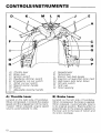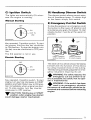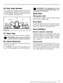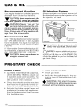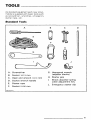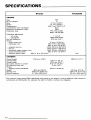
1
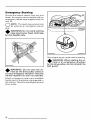
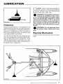
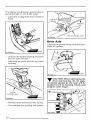
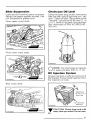
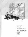
operator's manual 1987 414 5982 00 model V.I.N. purchase date warranty expiry date To be completed by dealer at time of sale DEALER IMPRINT AREA AFTER SALES SERVICE BOMBARDIER INC. VALCOURT (QUEBEC) CANADA, JOf 2LO H Litho'd in Canada ~ Duality Service The following are trademarks of Bombardier Inc. ALPINE® BLIZZARD® BOMBARDIER® CARRY-BOOSE® CITATION® ELAN® ELITE® ESCAPADE* EVEREST® FORMULA* FUTURA® GRAND PRIX SPECIAL® MIRAGE® MOTO-SKI® NORDIK® NUVIK® OLYMPIQUE® ROTA X® ®*Trademarks of Bombardier Inc. SAFARI* SKANDIC® SKI-DOO® SONIC® SPIRIT® STRATOS* T'NT® TUNDRA* All rights reserved © Bombardier. Inc. FOREWORD The operator manual and the Snowmobile Safety Handbook have been prepared to acquaint the owner/operator or passenger of a new snowmobile with the various vehicle controls, maintenance and safe operating instructions. Each is indispensable for the proper use of the product, and should be kept with the vehicle at all times. Should you have any questions pertaining to the warranty and its application, please consult the ''Often Asked Questions'' section of this manual, or your authorized dealer. This manual uses the following symbols. WARNING: Identifies an instruction which, if not followed, could • cause serious personal injuries including possibility of death. -.r CAUTION: Denotes an instruction T which, if not followed, could severely damage vehicle components. 0 NOTE: Indicates supplementary information needed to fully complete an instruction. Although the mere reading of such information does not eliminate the hazard, your understanding of the information will promote its correct use . WARNING: The engines and the corresponding components iden• tified in this manual should not be utilized on product(s) other th9n those mentioned on the cover page of this manual. The information, illustrations and components/system descriptions contained in this manual are correct at time of publication. Bombardier Inc. however, maintains a policy of continuous improvement of its products without imposing upon itself any obligation to install them on products previously manufactured. Bombardier Inc. reserves the right at any time to discontinue or change specifications, designs, features, models or equipment without incurring obligation. The illustrations show the typical construction of the different assemblies and, in all cases, may not reproduce the full detail or exact shape of the parts shown, however, they represent parts which have the same or a similar function. Most specifications are given in both metric and customary units. Where precise accuracy is not required, some conversions are rounded to even numbers for easier use. A shop manual can be obtained for complete service, maintenance and repair information. -.r CAUTION: Several components T of this vehicle are built with parts dimensioned in the metric system. Most fasteners are metric and must not be replaced by customary fasteners or vice versa. Mismatched or incorrect fasteners could cause damage to the vehicle or possible personal injury. SAFETY MEASURES Observe the following precautions: • Your snowmobile is not designed to be operated on public streets, road or highways. In most States and Provinces, it is considered an illegal operation. • Throttle mechanism should be checked for free movement before starting engine. • Installation of other than standard equipment, including ski-spreaders, bumpers, pack racks, etc., could severely affect the stability and safety of your vehicle. Avoid adding on accessories that alter the basic vehicle configuration. • The snowmobile engine can be stopped by activating the emergency cutout or tether switches or turning off the key. • Clean and check operation of the headlight tail light and brake light. • Engine should be running only when belt guard and/or pulley guard is secured in place. • Whenever the vehicle is parked outdoors, overnight or for a long period, it is suggested to protect it against the inclemency of the weather with a snowmobile cover. • Never run the engine without drive belt installed. Running an unloaded engine can prove to be dangerous. • Do not lubricate throttle and/or brake cables and housings. • Never run the engine when the track is raised off the ground. • Only perform procedures as detailed in this manual. Unless otherwise specified, engine should be turned OFF for all lubrication and maintenance procedures. • It can be dangerous to run engine with the hood removed. • Gasoline is flammable and explosive under certain conditions. Always manipulate in a well ventilated area. Do not smoke or allow open flames or sparks in the vicinity. If gasoline fumes are noticed while driving, the cause should be determined and corrected without delay. • The Stratos model is designed for the driver only. No provisions have been made for a passenger. • Should removal of a nylon lock nut be required when undergoing repairs/disassembly, always replace by new ones. Tighten as specified in the applicable Shop Manual. • Maintain your vehicle in top mechanical condition at all times. • Your snowmobile is not designed to be driven or operated on black top, bare earth, or other abrasive surfaces. On such surfaces abnormal and excessive wear of critical parts is inevitable. PLEASE READ AND UNDERSTAND ALL WARNINGS AND CAUTIONS IN THIS MANUAL AND ON THE VEHICLE. THIS MANUAL SHOULD REMAIN WITH THE VEHICLE AT THE TIME OF RESALE. 2 --------------------------- INDEX------------THE 1987 "LIMITED WARRANTY". 4 OFTEN ASKED QUESTIONS .. 6 LISTING OF AREA DISTRIBUTORS ...... . 8 9 HOW TO IDENTIFY YOUR SNOWMOBILE . CONTROLS/INSTRUMENTS Throttle lever, brake lever, ignition switch, headlamp dimmer switch, emergency cut-out switch, tether cut-out switch, rewind starter handle, primer, adjustable steering handle, speedometer, tachometer, electric fuel level gauge, injection oil level pilot lamp, high beam pilot lamp, hot grip switch, tank cap, hood opening, seat belt, tool box, fuse holders . . . . . . . . . . . . . . . . . . . . . 10 BREAK-IN PERIOD Engine and belt break-in, 10 hour-inspection, inspection check list 14 GAS & OIL Recommended gasoline, recommended oil, oil injection system . . 16 PRE-START CHECK 16 Check points .............. . STARTING PROCEDURE Manual starting, electric starting, before riding, emergency starting . . 17 LUBRICATION Frequency, steering mechanism, drive axle, slide suspension, chaincase oil level, oil injection system ................. 19 MAINTENANCE Maintenance chart, belt guard removal and installation, drive belt removal, drive belt condition, new drive belt, brake condition, brake adjustment, spark plugs, battery, suspension condition, stopper strap condition, suspension adjustment, stopper strap, track condition, track tension and alignment, drive pulley, steering mechanism, steering adjustment, muffler attachments, engine head nuts, engine mount nuts, carburetor adjustment, oil injection system, fan belt, headlamp beam aiming, bulb replacement, general inspection 22 STORAGE Track, suspension, skis, controls, chaincase, drive pulley, engine and primer lubrication, gas tank and carburetor, battery, chassis, general inspection, suspension stopper strap . . . ............................. 34 PRE-SEASON PREPARATION Pre-season preparation chart .... . 38 TROUEtLE SHOOTING GUIDE . . . 39 TOOLS .............. . 41 SPECIFICATIONS ........ . 42 WIRING DIAGRAMS ........ . 44 46 Sl INFORMATION GUIDE ...... . ---------------------------3 THE 1987 SNOWMOBILE LIMITED W A R R A N T Y - - - - - - - - - 1 -PERIOD BOMBARDIER® INC. as manufacturer, warrants FROM THE DATE OF FIRST CONSUMER SALES, every 1987 BOMBARDIER snowmobile, sold as NEW AND UNUSED, and predelivered by an authorized BOMBARDIER dealer for a period of: • 12 consecutive months. 2 - WHAT BOMBARDIER WILL DO BOMBARDIER will repair and/or replace, at its option, components defective in material and/or workmanship (under normal use and service,) with a genuine BOMBARDIER component without charge for parts or labour, at any authorized BOMBARDIER dealer during said warranty period. 3- CONDITION TO HAVE WARRANTY WORK PERFORMED Present to the servicing dealer, the hard copy of the BOMBARDIER Warranty Registration card or proof of purchase received by the customer from the selling dealer at time of purchase. 4- WARRANTY TRANSFER This warranty is transferable to subsequent owner(s) for remainder of warranty period from original date of sale. 5- EXCLUSIONS- ARE NOT WARRANTED • Normal wear on all items such as, but not limited to: - drive belts - bulbs - slider shoes - runners on skis - spark plugs • Replacement parts and/or accessories which are not genuine BOMBARDIER parts and/or accessories. • Damage resulting from installation of parts other than genuine BOMBARDIER parts. • Damage caused by failure to provide proper maintenance as detailed in the Operator's Manual. The labour, parts and lubricants costs of all maintenance services, including tune-ups and adjustments will be charged to the owner. • Vehicles designed and/or used for racing purposes. • All optional accessories installed on the vehicle. (The normal warranty policy for parts and accessories, if any, applies). • Damage resulting from accident, fire or other casualty, misuse, abuse or ne glect. • Damage resulting from operation of the snowmobile on surfaces other thar snow. • Damage resulting from modification to the snowmobile not approved in writ ing by BOMBARDIER. 4 ---------------------------- • Losses incurred by the snowmobile owner other than parts and labour, such as, but not limited to, transportation, towing, telephone calls, taxis, or any other incidental or consequential damage. 6 - BATTERY WARRANTY: • 12 consecutive months. (Pro-rated) 100% warranty coverage will start on the date the snowmobile was purchased and run to the following April 30th. The remainder of the 12 month period will be pro-rated as follows: - 50% from April 30th to December 1st. - 40% from December 1st to December 31st. - 30% from January 1st to end of warranty. 7 - EXPRESSED OR IMPLIED WARRANTIES This warranty gives you specific rights, and you may also have other legal rights which may vary from state to state, or province to province. Where applicable this warranty is expressly in lieu of all other expressed or implied warranties of BOMBARDIER, its distributors and the selling dealer, including any warranty of merchantability or fitness for any particular purpose; otherwise the implied warranty is limited to the duration of this warranty. However, some states or provinces do not allow limitations on how long an implied warranty lasts, so the above limitation may not apply. Neither the distributor, the selling dealer, nor any other person has been authorized to make any affirmation, representation or warranty other than those contained in this warranty, and if made, such affirmation, representation or warranty shall not be enforceable against BOMBARDIER or any other person. Some states or provinces do not allow the exclusion or limitation of incidental or consequential damages, so the above limitation or exclusion may not apply. BOMBARDIER INC. reserves the right to modify its warranty policy at any time, being understood that such modification will not alter the warranty conditions applicable to vehicles sold while the above warranty is in effect. 8 · CONSUMER ASSISTANCE If a servicing problem or other difficulty occurs, we suggest the following: 1. Try to solve the problem at the dealership with the Service Manager or Owner. 2. If this fails, contact your area distributor listed in the Operator's Manual. 3. Then if your grievance still remains unsolved, you may write to us: Bombardier Inc. Service Department Recreational Products Division Valcourt (Quebec). Canada, JOE 2LO February 1986 Bombardier Inc. Valcourt (Quebec). Canada, JOE 2LO ®*Trademarks of Bombardier Inc. ___________________________ 5 OFTEN ASKED QUESTIONS------------0: Why must my snowmobile be registered? After all I do have my original invoice as proof of when I purchased my snowmobile. A: Your warranty is valid at any authorized dealer of the product. Your registration is the key element in providing the servicing dealer with the necessary data to complete warranty claim forms. This information is also used to notify owners in the event of a safety recall. 0: Who should send the registration card to Bombardier Inc.? A: The dealer. However, It is important that the customer make sure that it has been sent. The company might contact you should your vehicle be recalled or in case of a particular warranty campaign. 0: I bought my snowmobile in O'King County but I snowmobile in Washington County. Can the dealer in Washington County accept to perform warranty work on my snowmobile? A: Yes, any authorized dealer in North America can perform warranty repairs, providing the customer warranty registration card is presented. 0: Where can I find information on the lubrication and maintenance of my snowmobile? A: In this Operator Manual prov1ded with the vehicle at the time of first sale. 0: Will the entire warranty be void or cancelled, if I do not operate or maintain my new snowmobile exactly as specified in the Operator's Manual? A: The warranty of the new snowmobile cannot be "Vo1ded" or "Cancelled': However, if a particular failure is caused by operation or maintenance other than is shown in the Operator Manual, THAT failure may not be covered under warrant)!. This includes service work performed by the customer, especially the critical adjustments to ignition, timing, carburation and oil injection/or oil mixture. 0: Would you give some examples of abnormal use or strain, neglect or abuse? A: These terms are general and overlap each other in areas. Some specific examples may include: running the machine out of 01/, chain fa1lure caused by a lack of lubrication, operating the machine with a broken or damaged part which causes another part to fa1/, and so on. If you have any specific questions on operation or maintenance, please contact your dealer for advice. 6 _ _ _ _ _ _ _ _ _ _ _ _ __ 0: What costs are my responsibility during the warranty period? A: The customer's responsibility includes all costs of normal maintenance services, non-warranty repairs, acc1dents and collision damage, as well as oils, and spark plugs, and incidental or consequential damages costs as explained in the warranty. 0: Are "Genuine" Bombardier replacement parts used in warranty repairs covered by warranty? A: Yes. When installed by an authorized dealer, any "genuine" Bombardier part used in warranty repairs assumes the remaining warranty that exists on the machine. 0: If I sell my snowmobile within the warranty period, will the new owner qualify for the balance of the warranty? A: Yes, prov1ded the unit has already been registered with the manufacturer. Note that the change of ownership card in this manual should be completed and sent to Bombardier Inc. 0: How can I receive the best owner assistance? A: The satisfaction and goodwill of the owners of Bombardier products are of primary concern to your dealer and Bombardier Inc. Normally, any problems that arise in connection with the sales transaction or the operation of your snowmobile will be handled by your Dealers Sales or Service Departments. It is recognized, however, that despite the best intentions of everyone concerned, misunderstandings will sometimes occur. If you have a problem that has not been handled to your satisfaction through normal channels, we suggest that you discuss your problem with a member of dealership management. Frequently, complaints are the result of a breakdown in communications and can quickly be resolved by a member of the dealership management. If the problem already has been reviewed with the Sales Manager or Service Manager, contact the Dealer himself or the General Manager. --------------------------- 7 LISTING OF AREA DISTRIBUTORS-----------CANADIAN DISTRIBUTORS AMERICAN DISTRIBUTORS Quebec Branch 1350 Nobel Boucherville (Quebec) J4B 1A1 (514) 655-6121 Province of Quebec BOMBARDIER CORPORATION All States (excluding Alaska) SERVICE OFFICES - East Main Street Road Malone, New York 12953 (518) 483-4411 Ontario Branch 230 Bayview Drive Barrie !Ontario) L4N 4Y8 (705) 728-8600 Province of Ontario Technical office P.O. Box 7060 Riverview (New Brunswick) E1B 1 VO (506) 386-6117 Atlantic Region BROOKS EQUIPMENT LIMITED 1 61 6 King, Edward Street P.O. Box 985 Winnipeg (Manitoba) R3C 2V8 1204) 633-7247 British Columbia, Manitoba, Saskatchewan, Alberta, Yukon CHARLES R. BELL LIMITED Newfoundland, Labrador Offices - Riverside Drive P.O. Box 1050 Corner Brook (Newfoundland) A2H 6J3 (709) 634-3533 Technical office (506) 386-6117 - 4505 West Superior Street P.O. Box 6106 Duluth, Minnesota 55816-016 1218) 628-2881 - P.O. Box 1569 Idaho Falls, Idaho, 83403 (208) 529-9510 NATIONAL SALES OFFICE - 0' Hare Lake Plaza 2350 Devon Avenue Suite 150 Des Plaines, Illinois 60018 1312) 298-9540 MILLER EQUIPMENT AND RECREATIONAL CENTER 1049 Whitney Road Anchorage, Alaska 99501 (907) 274-9513 Alaska - 81 Kenmount Road P.O. Box 8127 St-John's (Newfoundland) A 1 B 3N 1 (709) 722-6700 HUDSON'S BAY CO. LTD 165 Hymus Blvd Pointe-Claire (Quebec) H9R 1G2 1514) 697-8500 North-West Territories, Franklin District & Keewatin 8 -------------- HOW TO IDENTIFY YOUR SNOWMOBILE----------The main components of your snowmobile (engine, track and frame) are identified by different serial numbers. It may sometimes become necessary to locate these numbers for warranty purposes or to trace your snowmobile in the event of theft. A009005002 A019000001 Vehicle serial number meaning: 0000 00000 ---rModel no Vehicle no A000000013 0 NOTE: We strongly recommend that you take note of all the serial numbers on your vehicle and supply them to your insurance company. It will surely help in the event a snowmobile is stolen. ---------------------------- 9 CONTROLS/INSTRUMENTS A B ~~1-..1...-~---c ~...J....._____J.__ _ 0 ~'-------L--- G \----4l!J.4=j'------ Q L.....::::~~=--U--!----P Q A) 8) C) D) E) F) G) H) I) H Throttle lever Brake lever Ignition switch Head/amp dimmer switch Emergency cut-out switch Tether cut-out switch Rewind starter handle Primer Adjustable steering handle J) K) L) M) N) 0) P) 0) Speedometer Tachometer Electric fuel level gauge Injection oil level pilot lamp (red) High beam ptlot lamp (blue) Hot grip switch Tank cap Hood opening A019007002 A) Throttle Lever B) Brake Lever Located on the right side of handlebar. When compressed, it controls the engine speed and the engagement of the transmission. When released, engine speed returns automatically to idle. Located on the left side of handlebar. When compressed, the brake is applied. When released, it automatically returns to its original position. Braking effect is proportionate to the pressure applied on the lever and to the type of terrain and its snow coverage. 10 - - - - - - - - - - - - - C) Ignition Switch 0) Headlamp Dimmer Switch The lights are automatically ON whenever the engine is running. The dimmer switch allows correct selection of headlamp beam. To obtain high or low beam simply flick switch. Manual Starting E) Emergency Cut-Out Switch OFF A002007002 CB -ON -NOT IN USE To stop the engine in an emergency, push the button to the lower off position and simultaneously apply the brakes. To start engine, button must be at the upper on position. +OFF Key operated, 3 position switch. To start the engine, first turn the key clockwise to ON position. To stop the engine, turn the key counter-clockwise to OFF position. The 3rd position is not in use. Upper position before starting Electric Starting Lower position to stop engine A017006004 OFF A002007002 CB - ON -START Key, operated, 3 position switch. To start engine, turn key fully clockwise to START position and hold. Return key to ON position immediately when engine has started. To stop engine, turn key counterclockwise to OFF position. The driver of this vehicle should familiarize himself with the function of this device by using it several times on first outing. Thereby being mentally prepared for emergency situations requiring its use. WARNING: For safety reasons, the emergency cut-out switch is ea• sily accessible; be careful not to operate it inadvertently. WARNING: If the switch has been • used in an emergency situation the source of malfunction should be determined and corrected before restarting engine. , . , CAUTION: Holding key in START T position when engine has started could damage starter mechanism. 11 F) Tether Cut-Out Switch J) Speedometer Attach tether cord to wrist or other convenient location of the driver's clothing. Snap tether cut-out cap over receptacle before starting engine. The speedometer is linked directly to the drive axle. Direct-reading dial indicates the speed of the vehicle. Odometer records the total distance travelled in kilometers. If emergency engine "shut off" is required, completely pull cap from safety switch and engine power will be automatically shut "off". 0 NOTE: The cap must be installed on the safety switch at all times in order to operate the vehicle. WARNING: If the switch is used in an emergency situation the sour• ce of malfunction should be determined and corrected before restarting engine. G) Rewind Starter Handle Auto rewind type located on right hand side of vehicle. To engage mechanism, pull handle. H) Primer Pull and push button (2-3 times) to activate primer. The primer should always be used for cold engine starts. When engine is warm however, it is not necessary to use primer when starting. I) Adjustable Steering Handle - Remove steering pad. - Loosen the four (4) retaining screws. - Adjust the handle to the desired position. K) Tachometer The tachometer registers the impulses of magneto. Direct-reading dial indicates the number of revolutions per minute (RPM) of the engine. "W' CAUTION: The tachometer is proT tected by a fuse, if tachometer stops operating check fuse condition and if necessary replace. The fuse is 0.1 amp. Do not use a higher rated fuse as this can cause severe damage to the tachometer. L) Electric Fuel Level Gauge The electric fuel gauge is located in the dashboard and allows driver to observe the fuel level while riding the snowmobile. M) Injection Oil Level Pilot Lamp (Red) Will light up when injection oil level is low. Check level and replenish as soon as possible. "W' CAUTION: Do not run engine un- T til it is out of oil. Serious engine damage will occur. Whenever brake lever is compressed, oil level pilot lamp should light up. If not, replace lamp. WARNING: Do not adjust too high • as the brake lever may contact the windshield when turning. - Lock the steering handle in place by tightening the four (4) retaining screws to 26 N•m (19 lbf•ft). - Reinstall steering pad. N) High Beam Pilot Lamp (Blue) Lights up when headlamp is on high beam. 12 -------------------------- 0) Hot Grip Switch The 3 position toggle switch is located in dashboard underneath pilot lamps. Select the desired position to keep hands at a comfortable temperature. OFF WARM HOT WARNING: It is dangerous to run an engine with the hood open, un• fastened or removed. Seat Belt (Escapade only) Located on middle of seat. Provide a grip for the rear passenger. Tool Box Located under the hood. To gain access, tilt hood. Ideal location for spare plugs, rope, first aid kit, flashlight, etc. A019007003 Fuse Holders Starter (electric starting) P) Tank Cap Unscrew to fill up tank then fully tighten. • WARNING: Never use a lit match or open flame to check fuel level. Starting system is protected with a 30 amperes rated fuse. Fuse holder is located near the starter. If starter does not operate, check fuse condition and if necessary replace. Q) Hood Opening Tachometer Pull down the latches to unlock the hood from the anchor. The tachometer is protected with 0.1 ampere rated fuse. Fuse holder is located under the hood behind the tachometer. If it stops operating, check fuse condition and replace if necessary. 0 NOTE: Always lift hood gently up until stopped by restraining device. 13 BREAK-IN PERIOD Engine Belt With Bombardier-Rotax snowmobile engines, a break-in period is required before running the vehicle at full throttle. Engine's manufacturer recommendation is 10 to 15 operating hours. During this period, maximum throttle should not exceed 3/4, however, brief full acceleration and speed variations contribute to a good break-in. Continued wide open throttle accelerations, prolonged cruising speeds, and lugging are detrimental during the break-in period. NOTE: To assure additional protection during the initial engine breakin, 500 ml (18 imp. oz) of BLIZZARD OIL should be added to gas for the first full gas tank filling. A new drive belt requires a break-in period of 25 km (15 miles). 0 'W' CAUTION: Remove and clean spark T plugs after engine break-in. 1 0-Hour Inspection As with any precision piece of mechanical equipment, we suggest that after the first 10 hours of operation or 30 days after the purchase, whichever comes first, your vehicle be checked by your dealer. This inspection will give you the opportunity to discuss the unanswered questions you may have encountered during the first hours of operation. Remember that it is easier to remedy at this time than to allow the snowmobile to operate until a possible failure occurs. The 10 hour inspection is at the expense of the vehicle owner. 14 - - - - - - - - - - - - - 10-HOUR INSPECTION CHECKLIST .I Engine timing Fan belt tension Spark plugs condition: (Remove and clean) Carburetor adjustment Oil injection pump adjustment Engine head nuts Engine mount nuts Muffler attachment Chaincase oil level Injection system oil level Brake operation and lining condition Ski alignment (runner condition) Handlebar bolts, retorque to 26 N•m (19 lbf•ftl Pulley alignment and drive belt condition Track condition, tension and alignment Lubrication (steering, suspension, drive axle) Electrical wiring (loose connections, stripped wires, damaged insulationl. tighten all loose bolts, nuts and linkage Operation of lighting system (HI I LO beam, brake light, etc.), test operation of emergency cut-out switch and tether switch Battery electrolyte level (electric starting) We recommend that you have your dealer sign this inspection list. Date of 10 hour inspection Dealer signature ---------------------------- 15 GAS & OIL Recommended Gasoline Oil Injection System Use regular leaded or unleaded gasoline available from all service stations. Always maintain a sufficient amount of Bombardier Snowmobile injection oil in the injection oil tank. ,.,. CAUTION: Never experiment with T different fuel, never use naphtha, methanol, gasohol or similar products . WARNING: Never "top up" the gas tank before placing the vehi• cle in a warm area. At certain temperatures, gasoline will expand and overflow. Always wipe off any gasoline spillage from the snowmobile. Recommended Oil Use "Bombardier Snowmobile Injection Oil" (P/N 496 0133 00- 1 liter) available from the dealer. This type of oil will flow at temperatures as low as minus 40°C (-40°F). If "Bombardier Snowmobile Injection Oil" is unavailable, substitute with BLIZZARD OIL. (P/N 496 0135 00- 500 ml). ,.,- CAUTION: Never use outboard or T straight mineral oils. ,.,-CAUTION: Check level and refill T every time you refuel. Do not overfill. 0 NOTE: To assure additional protection during the initial engine breakin, 500 ml (18 imp. oz) of BLIZZARD OIL should be added to gas for the first full gas tank filling. PRE-START CHECK _ _ _ _ _ __ Check Points • Check injection oil level. • ACTIVATE THE THROTTLE CONTROL LEVER SEVERAL TIMES to check that it operates easily and smoothly. The throttle control lever must return to idle position when released. • Check gas level. • Check that the skis and the track are not frozen to the ground or snow surface and that steering operates freely. • Activate the brake control lever and make sure the brake fully applies before the brake control lever touches the handlebar grip. 16 _________________________ • Verify that the path ahead of the vehicle is clear of bystanders and obstacles. WARNING: Only start the snow• mobile once all components are checked and functioning properly. STARTING PROCEDURE ___________________________ Test throttle control lever. Check that the emergency cut-out switch is in the ON position. .,.,. CAUTION: To avoid starter overT heating, the cranking period should never exceed 30 seconds and a rest period should be observed between the cranking cycles to let starter cool down. Release key immediately when engine has started. If engine does not start on first try, key must be turned fully back to OFF each time. • A017ooaoo4 Upper position before starting engine Ensure the tether cut-out cap is in position and that the cord is attached to the clothing. Activate the primer (2 or 3 times). 0 NOTE: The use of the primer is not necessary when the engine is warm. Manual Starting Insert the key in the ignition and turn to ON position. Grasp manual starter handle firmly and pull slowly until a resistance is felt then pull vigorously. Slowly release the rewind starter handle . • WARNING: Do not apply throttle while starting. 0 NOTE: If for some reason the vehicle cannot be started electrically, place ignition key to ON position and start engine manually. Before Riding Check operation of the emergency cutout switch, and tether switch. Restart engine. WARNING: lfenginedoesnotshutoff when applying the emergency • cut-out switch and or when pulling the tether cut-out cap, stop the engine by turning off the ignition key. Do not operate the vehicle further, see the dealer. Allow the engine to warm before operating at full throttle. WARNING: Do not apply throttle while starting. Electric Starting .,.,. CAUTION: Never operate your T snowmobile with the battery removed or disconnected. Since the battery reduces voltage fluctuations, operating vehicle without battery might cause instrument or bulb failure. Turn ignition key clockwise until starter engages. - - - - - - - - - - - - - - 17 Emergency Starting Should the rewind starter rope fray and break, the engine can be started with an emergency starter rope supplied with the tool kit. 0 NOTE: The spark plug socket can be used as an emergency starter grip. • WARNING: Do not wind starting rope around your hand. Hold rope by the handle only. A019003001 A003003016 Start engine as per usual manual starting . A007003030 WARNING: Do not start the vehicle by the drive pulley unless it • is a true emergency situation. Have the vehicle repaired as soon as possible. Attach emergency rope to any available handle and to the starter clip supplied in the tool box. Wind the rope thightly around drive pulley. 18 - - - - - - - - - - - - - WARNING: When starting the vehicle in an emergency situation • by the drive pulley, do not reinstall the belt guard . LUBRICATION 0 NOTE: When lubricating grease fittings, grease until grease appears at joints. Always use low temperature grease (P/N 413 7061 00) . A000000007 Frequency Routine maintenance is necessary for all mechanized products, and the snowmobile is no exception. A weekly vehicle inspection contributes to the life span of the snowmobile as well as retains safe and dependable operation. It is recommended that the steering system and suspension be lubricated monthly or every 40 hours of operation. If the vehicle is operated in wet snow or in severe conditions these items should be lubricated more frequently. WARNING: Only perform such procedures as detailed in this manu• al. It is recommended that dealer assistance be periodically obtained on other components/systems not covered in this manual. Unless otherwise specified, engine should be turned OFF for all lubrication and maintenance procedures . WARNING: Do not lubricate throttle and/or brake cables and hous• ings. Steering Mechanism Oil ball joints and steering column bushings. A019006001 19 The following lubrication points have to be performed on LH & RH sides: - Lubricate ski leg shaft from inside of hood. Drive Axle Lubricate at grease fitting using low temperature grease. ... - Unhook ski leg boot spring and raise boot to gain access. - Lubricate ski pivot and ski leg lower bushing. ... A009003010 1lllr CAUTION: When lubricating the drive axle bearing, do not apply excessive grease as the seal will be pushed out of its housing. Check seal posi!ion with finger. T '-.... A019006003 I'' - Reinstall boot and secure the spring. - Coat stabilizer bar bushing with grease. 20 _________________________ Slide Suspension Chaincase Oil Level Lubricate the following parts at grease fittings until grease appears at joints. Use low temperature grease only. Using the spark plug socket, remove the filler cap then using a rigid wire as a "dipstick" check oil level. The oil level on the "dipstick" should be 50-65 mm (2" to 2 1/2"). Refill as required using Bombardier chaincase oil (P/N 413 8019 00200 ml). Front upper cross shaft. Front lower cross shaft. A009003011 0 NOTE: The chaincase oil capacity is approximately 200 ml (7 oz). Oil Injection System Always maintain a sufficient amount of Bombardier Snowmobile Injection Oil in the injection oil tank. Rear cross shaft. -,.,.CAUTION: Check level and refill T every time you refuel. Do not overfill. -------------------------- 21 MAINTENANCE The following Maintenance Chart indicates regular servicing schedules to be performed by the owner of the servicing dealer. If these services are performed as suggested, the snowmobile will provide many years of low-cost use. MAINTENANCE CHART WARNING: Only perform such procedures as detailed in this manual. • It is recommended that dealer assistance be periodically obtained on other components/systems not covered in this manual. Unless otherwise specified, engine should be turned OFF for all lubrication and maintenance procedures . .E .E 0 0 0 "'= >i::"E ::!20>~ ~a;o :s:~<t ON "' -'=' i::" E ..c.,.., §~o ~~o coo Q) Cl :o E ==~ ::-.., E "'c. B Q)~o8 UQ)Oo ~ OoM- c: C,_NN Q) Carburetor adjustment 0 NOTE: The ten hour inspection is a very important part of proper service and mamtenance. 22 __________________________ Belt Guard Removal WARNING: Engine should be running only when belt guard is se• cured in place. 1. Tilt the hood. 2. Pull out both retaining pins. 4. Slip slackened belt over the top edge of the sliding half. 3. Lift and remove the belt guard assembly. Drive Belt Removal and Installation WARNING: Never start or run engine without the drive belt install• ed. Running an unloaded engine is dangerous. 1. Remove the belt guard. A004003008 5. Slip the belt out from the drive pulley and remove completely from vehicle. 2. Unlock and raise driven pulley support. Driven pulley support A004003006 3. Open the driven pulley by twisting and pushing the sliding half. Hold in fully open position. A004003009 To install the drive belt, reverse the procedure, however pay attention to the following. - - - - - - - - - - - - - 23 The maximum drive belt life span is obtained when the belt has the proper rotation direction. Install it so the printed information on the belt is in the way to be read when standing face to pulleys. CORRECT .. -:. "'•'•''·' ''AI'A"-H "' · 1 Identification STANDING FACE TO PULLEYS A001003002 INCORRECT Check the drive belt width. If less than 32 mm (1 1/4 in), replace the drive belt. New Drive Belt When installing a new drive belt, breakin period of 25 km (15 miles) is strongly recommended. 0 NOTE: Always store a spare belt in a manner to allow its natural shape to be maintained . Brake Condition The brake mechanism on the snowmobile is an essential safety device. Keep this mechanism in proper working condition. Above all, do not operate the snowmobile without an effective brake system . WARNING: Brake pads less than 3 mm (1/8") thick must be replac• ed. Replacement must be performed by an authorized dealer. A001003003 -.r CAUTION: Do not force or use tools to pry the belt into place, as this could cut or break the cords in the belt. T Drive Belt Condition Inspect belt for cracks, fraying or abnormal wear (uneven wear, wear on one side, missing cogs, cracked fabric). If abnormal wear is noted, probable cause could be pulley misalignment, excessive R.PM. with frozen track, fast starts without warm-up period, burred sheave, oil on belt or distorted spare belt. Contact the dealer. 24 __________________________ A009003013 Brake pads 3 mm (118") MINIMUM thickness Brake Adjustment The brake mechanism is a self-adjusting type. If a quicker brake response is desired, strongly pull the brake lever several times, this will actuate the self adjusting mechanism. Fouled (black) Overheated (light grey) A000004010 Strongly pull Normal (brownish) ~CAUTION: A008006002 If spark plug condition is not ideal, contact your authorized dealer. T After the adjustment, brake should apply fully when lever is approximatively 13 mm ( 112") from handlebar grip. If not, do not tamper with the brake, contact the dealer. Check spark plug gap using a wire feeler gauge. Reinstall spark plugs and connect wires. Battery (Electric Starting) 13 mm (112") approx. Check electrolyte level weekly. Electrolyte level must be at upper level line on battery casing. A008006002 Spark Plugs Disconnect the spark plug wires and remove the spark plugs. Check the condition of the plugs. Maximum levei...LJ..J........,.__ Minimum level • A brownish tip reflects ideal conditions. Carburetor adjustments, spark plug heat range, etc., are correct). • A black insulator tip indicates fouling caused by: carburetor idle speed mixture and/or high speed mixture too rich, incorrect fuel mixture ratio, wrong type of spark plug (heat range), or excessive idling. • A light grey insulator tip indicates a lean mixture caused by: carburetor high speed mixture adjusted too lean, wrong spark plug heat range, incorrect fuel mixture ratio, or a leaking seal or gasket. A009004011 If necessary add distilled water. Battery connections must also be free of corrosion. If clroaning is necessary remove corrosion using a stiff brush then clean with a solution of baking soda and water. Rinse and dry well. ~CAUTION: Do not allow cleaning T solution to enter battery. It will destroy the chemical properties of the electrolyte. --------------------------- 25 After reconnecting battery, coat battery terminals and connectors with petroleum jelly to prevent corrosion. Check that battery is well secured and that battery vent tube is not kinked or blocked. Suspension Adjustment Front Suspension The preload of front suspension shock absorber spring can be adjusted as follows: POSITION WARNING: Vent tube must be free and open. If not, it will re• strict ventilation and create a gas accumulation that could result in an explosion. Avoid skin contact with electrolyte. CONDITION Lowest Soft riding, smooth trail Middle Normal riding Highest Hard surface Unhook ski leg boot spring and raise boot to gain access. To adjust, use special key supplied in the tool box and turn spring collar accordingly. 'W' CAUTION: Prior to charging the T battery, always remove it from the vehicle to prevent electrolyte spillage. A019001001 0 NOTE: Always keep battery fully charged. (To charge, refer to "Battery" in "Storage" section). Suspension Condition Visually inspect all suspension components including slider shoes, springs, wheels, etc. 0 NOTE: During normal driving, snow will act as a lubricant and coolant for the slider shoes. Extensive riding on ice or sanded snow, will create excessive heat build-up and cause premature slider shoe wear. Stopper Strap Condition Inspect strap for wear and cracks, bolt and nut for tightness. If loose inspect holes for deformation, replace as required. Torque nut to 10 N•m (89 lbf•in). 26 __________________________ A019005003 Reinstall boot and secure the spring. Rear Suspension ADJUSTER BLOCKS & SHOCK ABSORBER SPRINGS The rear suspension is adjustable. The front adjuster blocks for surface condition, the rear shock absorber springs for driver's weight. Use special keys supplied in tool box. ADJUSTER BLOCKS Use this key to adjust 0 NOTE: For deep snow condition or hill climbing, it is recommended to place the front adjuster blocks on the lowest position and set stopper strap to the shortest position. .._,CAUTION: Always turn the left T side adjuster blocks in a clockwise direction, the right side blocks in a counter-clockwise direction. Left and right adjuster blocks of each adjustment must always be set at the same elevation. SHOCK ABSORBER SPRINGS Use this key to adjust. A019001002 When the front adjuster blocks are at the lowest elevation more weight is distributed on the skis. A019001001 Adjuster blocks Driver's weight The preload of shock absorber springs can be adjusted as follow: POSITION DRIVER'S WEIGHT kg (lb) FROM UP TO Lowest - 68 (150) Middle 68 (150) 82 (180) Highest 82 (180) - To adjust, turn spring collar accordingly. A019000002 A021005001 At the highest position the weight is transferred from the skis to the track. Driver's weight Surface condition A019000002 - - - - - - - - - - - - - 27 STOPPER STRAP Track Tension and Alignment The function of the suspension stopper strap is to control the transfer of vehicle weight during acceleration. The longer the belt, the more the weight will be transferred to the track to provide a better traction. The shorter the belt, the lesser the weight transferred to the track, thus maintaining a more positive direction. Adjusting holes on the stopper strap allow to adjust it according to drivers' requirements, field and or snow conditions. Tension Lift the rear of vehicle and support with a mechanical stand. Allow the slide to extend normally. The gap should be 13 mm (112") between the slider shoe and the bottom inside of the track. If the track tension is too loose, the track will have a tendency to thump. For normal use, insert bolt through strap holes as shown: Torque to 10 N•m (89 lbf•inl A019000002 (13 mm (lt2") "1llr CAUTION: Too much tension will T result in power loss and excessive stresses on suspension components. If necessary to adjust; loosen the rear idler wheel retaining screw and the adjuster bolt lock nut; then loosen or tighten the adjuster bolts located on the inner side of the rear idler wheels. If correct tension is unattainable, contact the dealer. • WARNING: Always torque the nut to 10 N•m (891bf•in). Track Condition Lift the rear of the vehicle and support it off the ground. With the engine OFF, rotate the track by hand, and inspect condition. If worn or cut, or if track fibers are exposed, or if missing or defective inserts or guides are noted; contact the dealer. WARNING: Do not operate a snowmobile with a cut, torn or dam• aged track. A019005005 28 ________________________ Adjuster bolt 0 NOTE: Track tension and alignment are inter-related. Do not adjust one without the other. Alignment Start the engine and accelerate slightly so that track turns slowly. Check that the track is well centered; equal distance on both sides between edges of track guides and slider shoes. A019005005 WARNING: Before checking track alignment, ensure that the track • is free of all particles which could be thrown out while track is rotating. Keep hands, tools, feet and clothing clear of track. Ensure no-one is standing in close proximity to the vehicle. To correct, stop the engine, loosen the rear idler wheels retaining screws then loosen the lock nuts and tighten the adjuster bolt on side where the slider shoe is the farthest to the track insert guides. Tighten lock nuts and the idler wheel retaining screws. Restart engine, rotate track slowly and recheck alignment. Drive Pulley These vehicles are equipped with the latest in snowmobile transmission system. The TRA drive pulley (Total Range Adjustable). This pulley includes three (3) calibration screws that provide the opportunity to perform minor adjustments to the clutch in order to keep the engine at it's peak power R.PM., thereby maintaining optimal vehicle performance. The clutch is factory adjusted position three (3) to provide the best performance under most riding conditions at sea level. However certain conditions, such as deep snow, high altitude, pulling a load, etc. may allow the engine to run below it's peak power R.PM. at wide open throttle thus decreasing the vehicle performance. Should such conditions be encountered the calibration screws can then be reset to allow the engine to operate at it's peak power R.PM. (given in technical data as max. HP R.P.M.). The adjustment may be set at any one of six (6) positions, numbered from 1 to 6. Note that for casting purposes numeral one (1) appears as a dot. Each of these positions provides an increase or a decrease, in numerical order, of the engine speed by approximately 200 R.P.M. - - - - - - - - - - - - - 29 Example: 0 (vehicle at sea level during full accel~r ation in normal conditions). ADJUSTMENT SCREW Position no 2 Position no 3 Position no 4 ENGINE SPEED 6800 R.P.M. 7000 R.P.M. (standard position) 7200 R.P.M. Positions two (2) and four (4) allow the engine to run below or above it's power peak. Reducing vehicle performance. 0 NOTE: One must bear in mind that the purpose of these calibration screws is to maintain the engine R.P.M. at it's peak power, a lower or upper speed will actually result in less vehicle performance. The point of maximum power, in the 1987 Stratos/Escapade occurs at about 7000 R.P.M. while the maximum permissible engine speed (red line) is 7500 R.P.M. Adjustment Procedure To change the calibration screw position; back off its locking nut and change the position of the calibration screw head. The notch on the screw head must be aligned with the desired numeral position. See illustration. .,.,. CAUTION: Back off the calibration T screw locking nut only far enough to allow a change of position of the screw head. Never attempt to remove the locking nut or the calibration screw. Make sure the adjustment is set at the same position for all three (3) screws . • Steering Mechanism Inspect the steering mechanism for tightness of components (steering arms, tie rods, ball joints, spring coupler bolts, etc.). If necessary, replace or retighten. WARNING: Check the condition of the skis and the ski runners. • Replace if more than half worn. Steering Adjustment Skis should have a toe out of 3 mm (1/8"). To check, measure the distance between each ski at the front and rear of the ski. The front distance should be 3 mm (1/8") more than the rear when the handlebar is horizontal. IMPORTANT: Close the front of the skis manually to eliminate all slack from the steering mechanism. WARNING: Always retorque locking nut to 10 N•m (89 lbf•in). A019006001 30 _________________________ If adjustment is required: Muffler Attachment Loosen the lock nuts of the longest tie rod. Turn the tie rod manually until the skis are properly aligned. Firmly retighten the lock nuts. The engine/exhaust system parts are vital toward efficient muffler function. Check all attachments. Replace the springs and/ or tighten if necessary. The handlebar should also be horizontal when the skis are pointed toward the front. , . , CAUTION: Do not operate vehicle ... with muffler disconnected otherwise serious engine damage will occur. To adjust: Engine Head Nuts Loosen the lock nuts of the shortest tie rod. Turn the tie rod manually until the handlebar is horizontal. Retighten the lock nuts firmly. With the ENGINE COLD, check that the engine head nuts are tight and equally torqued to 21 N•m (15 lbf•ft). WARNING: The ball joint socket • must run parallel with the steering arm. The socket must be restrained when tightening the tie rod end lock nuts. Respect tightening sequence as follow: (Typical) A007002002 IMPORTANT: The engine head nut torque should be checked after the first 5 hours of operation. A019006005 (Typical) Restrain Tighten Engine Mount Nuts Check the engine mount nuts for tightness. Retighten if necessary. -------------------------31 'W' CAUTION: An obstructed injecT tion oil filter will cause oil starva- Carburetor Adjustment 'W' CAUTION: Never operate your T snowmobile with the air intake silencer disconnected. Serious engine damage will occur if this notice is disregarded. tion resulting in serious engine damage. 0 NOTE: After a storage period, it is important that the dealer replace the injection oil filter and that the oil flow of the injection pump be checked. Injection Pump Adjustment A Proper oil injection pump adjustment is very important. Any delay in the opening of the pump can result in serious engine damage. 'W' CAUTION: The carburetor must T be adjusted before adjusting the oil injection pump. Make sure idle speed is 1800-2000 R.P.M. A) Air Screw Adjustment Completely close the air screw (until a slight reseating resistance is felt) then back off screw: 1 1/4 turn. 8) Idle Speed Adjustment Turn the idle speed screw clockwise until it contacts the throttle slide then continue turning two (2) additional turns. This will provide a preliminary idle speed setting. Start engine and allow it to warm then adjust idle speed to 1800-2000 R.PM. by turning idle speed screw clockwise or counter-clockwise. 'W' CAUTION: Make sure both carT buretors start to operate simultaneously. To check adjustment: eliminate the throttle cable free-play by pressing the throttle lever until a light resistance is felt then hold in place. The aligning marks on the pump casting and lever must align perfectly. If not, contact the dealer. 'W' CA~TION: Do not attempt to set T the 1dle speed by using the air screw. Severe engine damage can occur. If idle speed is unattainable contact the dealer. Oil Injection System Injection Oil Filter Condition Inspect oil filter at least once a month. Insure that filter is not obstructed by foreign particles; if so, see the dealer. 0 32 ________________________ NOTE: Injection pump should be adjusted by the dealer. Fan Belt Headlamp center line c:ex Inspect belt for cracks, uneven wear, etc. Check fan belt tension a 9-10 mm (3/8") deflection should exist. t TI !oo--.,rt 14 7.6 m (25'1 ~~ tc~~ 50 mm (2"1 Below headlamp center A002004010 Light beam (high beam projected on the wall) If belt seems damaged or if tension is incorrect, contact the dealer immediately. WARNING: If fan protector is removed, always reinstall after ser• vicing. 50 mm (2"1 Light beam center A002004007 Headlamp Beam Aiming The angle of the head lamp beam has been pre-adjusted prior to delivery. Should a readjustment is necessary, place the vehicle on a flat surface 7.6 m (25') from a wall or screen. To adjust, remove the four caps, turn upper or lower adjusting screws to obtain desired beam position. r - - - - Adjusting-----, screw With the suspension correctly adjusted, the rider seated on the vehicle and the high beam ON check that the center of high intensity zone of high beam is 50 mm (2") below horizontal line of headlamp height. ,___ _ _ Adjusting _ ____. screw A007004002 -------------------------33 Bulb Replacement If taillight bulb is burnt, expose the bulb by removing the red plastic lens. To remove, unfasten the two (2) screws. If the headlamp bulb is burnt, tilt hood, unplug the connector from the head lamp. Remove the rubber boot and unfasten bulb retainer clips. Detach the bulb and replace. Retainer~' 0 clips \ ~ • WARNING: Always check light operation after bulb replacement. General Inspection Check the electrical wiring and components, retighten loose connections. Check for stripped wires or damaged insulation. Thoroughly inspect the vehicle and tighten loose bolts, nuts and linkage. Inspect skis and ski runners for wear. STORAGE It is during summer, or when a vehicle is not in use for any length of time that proper storage is a necessity. Storage of the snowmobile during long period of inactivity consists of checking and replacing missing, broken or worn parts, proper lubrication and treatment to insure that parts do not become rusted; cleaning items such as carburetor of oil mixtures, to prevent gum varnish formation within the carburetor; and in general, preparing the vehicle so that when the time comes to use the snowmobile again it will be in top condition. WARNING: Only perform such procedures as detailed in this manual. • It is recommended that dealer assistance be periodically obtained on other components/systems not covered in this manual. Unless otherwise specified, engine should be turned OFF. For all lubrication and maintenance procedures. Track Inspect the track for wear, cuts, missing track guides and broken rods. Make any necessary replacement. WARNING: Do not operate a snowmobile with a cut, torn or dam• aged track. Lift the rear of vehicle until track is clear of the ground then support with a brace or trestle. The snowmobile should be stored in such a way that the track does not stay in contact with the cement floor or bare ground . 0 NOTE: The track should be rotated periodically, (every 40 days). Do not release track tension. W' CAUTION: To prevent track damT age, temperature in the storage area must not exceed 38°C (100°F). 34 __________________________ To perform the storage procedures (engine and primer valve) proceed as follows: Suspension Remove any dirt or rust. Grease all components equipped with grease fittings. Wipe off surplus. Replace worn slider shoes. 1. Lift the rear of the vehicle and support it off the ground. WARNING: Ensure the track is free of ails particles which could be • thrown out while it is rotating. Keep hands, tools, feet and clothing clear of track. Ensure no-one is standing in close proximity to the vehicle. Skis Wash or brush all dirt or rust accumulation from the skis. Grease the ski legs at the grease fittings. WARNING: Check the condition of the skis, ski runners and springs • Replace if weak or worn more than half. Controls Lubricate the steering mechanism. Inspect all components for tightness, (spring coupler bolts, steering arm locking bolts, tie rods, ball joints, etc.) Tighten if necessary. Oil moving joints of the brake mechanism. 2. Start the engine and allow it to run at idle speed until the engine reaches its operational temperature. 3. Stop the engine. 4. Disconnect the inlet primer hose from the primer valve. ygl Inlet WARNING: Do not lubricate the • throttle and/or brake cables and housings. Avoid getting oil on the brake pads. (Oblique Coat all electrical connections and switches with a greaseless metal protector. If unavailable, use petroleum jelly. Chaincase Outlet hose Drain the chaincase and refill to proper level, using fresh chain case oil (P/N 413 8019 00-200 ml). To drain, remove the chaincase cover. (Straight coupling) A002002009 5. Plug inlet primer hose to prevent gasoline from draining. 6. Using an appropriate hose, connect one end of the hose to the inlet of the primer valve and place the other end in a Bombardier Snowmobile Injection Oil container. Engine and Primer Lubrication 7. Activate the primer in order to fill it with oil. Engine internal parts must be lubricated to protect them from possible rust formation during the storage period. 8. Restart engine and run at idle. Drive Pulley Inspection and cleaning must be performed by the dealer at the end of each season. ________________________ 35 9. Using the primer valve, inject oil until the engine dies or until a sufficient quantity of oil has entered the engine (approximately 25 complete strokes of the primer). Reinstall plug. Check all fuel lines, replace if necessary. Battery 10. The engine stopped, remove the spark plugs and pour approximately 85 ml (3 imp. oz.) of oil into the cylinders. (Electric Starting) 11. Crank the engine to allow the crank- W' CAUTION: Be careful not to ground T positive terminal with the chas- shaft to turn 2 or 3 revolutions. 12. Reinstall the spark plugs and the inlet primer hose. 1. Disconnect the battery cables and remove the battery retainer cover. sis. Always disconnect black negative cable first. Do not run engine during storage period. Gas Tank and Carburetors Remove the cap then using a syphon, remove the gasoline from tank . WARNING: Gasoline is flammable and explosive under certain • conditions. Always manipulate in a well ventilated area. Do not smoke or allow open flames or sparks in the vicinity. Carburetors must be dried out completely to prevent gum formation during the storage period. Once the fuel tank is emptied, remove the float chamber drain plug from carburetors. Drain carburetors. 2. 3. Remove the battery vent tube from the vent hole. Lift out the battery. 4. Clean outside surface of battery with solution of baking soda and water. Remove all deposits from posts then rinse with clear tap water. .,.,. CAUTION: Do not allow cleaning T solution to enter battery interior since it will destroy the electrolyte. 5. Check electrolyte level. Refill if necessary with distilled water. Fully charge battery at a maximum rate of 2.0 A. A002002010 .,.,. CAUTION: Prior to charging the T battery, always remove it from the vehicle to prevent electrolyte spillage. 36 __________________________ WARNING: Gases given off by a battery being charged are highly • explosive. Always charge in a well ventilated area. Keep battery away from cigarettes or open flames. Avoid skin contact with electrolyte. Touch up all metal spots where paint has been scratched off. Spray all bare metal parts with metal protector. Wax the hood and the painted portion of the frame for better protection. 0 6. Coat electrical connections and switches with a greaseless metal protector, if unavailable, use petroleum jelly. NOTE: Apply wax on glossy finish only. Protect the vehicle with a cover to prevent dust accumulation during storage. 7. Store unit in a cool, dry place. "W' CAUTION: 0 NOTE: To prevent battery from discharging, store it on a wooden shelf away from moisture. A stored battery must be recharged at least every 40 days. Chassis Clean the vehicle thoroughly, removing all dirt and grease accumulation. "W' CAUTION: Plastic alloy com poT nents such as fuel tank, windshield, controls, etc., can be cleaned using mild detergents or isopropyl alcohol. Do not use strong soaps, degreasing solvents, abrasive cleaners, paint thinners, etc. Inspect the hood and repair any damage. Clean the frame. For the unpainted aluminum portion use only "Aluminum cleaner" and follow instructions on the container. If for some reason the snowmobile has to be stored outside it is necessary to cover it with an opaque tarpaulin. This caution will prevent the sun rays and grime from affecting the plastic components and the vehicle finish. T General Inspection Check the electrical wiring and components, retighten loose connections. Check for stripped wires or damaged insulation. Thoroughly inspect the vehicle and tighten loose bolts, nuts and linkage. 0 NOTE: Leave the drive belt off the pulleys for the entire storage pe- riod. Suspension Stopper Strap Replace annually and/or as condition dictates. Torque nut to 10 N•m (89 lbf•in). _________________________ 37 PRE-SEASON PREPARATION-----------IMPORTANT: Observe all Warnings and Cautions mentioned throughout this manual which are pertinent to the item being checked. When component conditions seem less than satisfactory, replace with genuine Bombardier parts or suitable equivalents. To simplify the pre-season preparation we have drawn up a small chart. The chart indicates servicing points to be performed by you and your dealer. If these services are performed as suggested, your vehicle will give many hours of fun and low cost use. PRE-SEASON PREPARATION CHART TO BE PERFORMED BY DEALER • TO BE PERFORMED BY OWNER 0 Reinstall battery (electric starting) Change spark plugs* Check chaincase oil level Replace fuel filter (located inside fuel tank) Check track tension and alignment Lubricate suspension Inspect drive belt and install Check steering alignment and ski runner condition Inspect condition of starting rope Check tightness of all bolts, nuts and linkage Refill gas tank Check throttle cable for damage and free operation Check electrical wiring (broken wire, damaged insulation) Inspect seals for possible cuts or leaks Replace injection oil filter Refill injection oil tank Inspect brake condition and operation Set engine timing Check pulleys, verify components and clean. Lubricate Adjust carburetors Adjust oil injection pump 0T 0 0 0 0 0 0 0 0 0 0 0 • • • • • • • • • 0 *NOTE: Before installing new spark plugs, it is suggested to burn the excess storage oil by starting the engine, using the old spark plugs. CAUTION: Only perform this procedure in a well ventilated area. 38 - - - - - - - - - - - - - TROUBLE SHOOTING 0 NOTE: The possible causes have been listed in an order of frequency. Therefore items should be checked out in the same order as mentioned in the trouble shooting guide. SYMPTOMS POSSIBLE CAUSES SOLUTIONS Engine turns over but fails to start or starts with difficulty 1. No fuel to the engine Check the tank level and fill it up with correct gas oil mixture. Check for possible clogging of fuel line, item 4. 2. Flooded engine Remove wet spark plugs, turn ignition to OFF and crank engine several times. Install clean dry spark plugs. Start engine following usual starting procedure. If engine continues to flood, see your dealer. 3. Spark plug/faulty ignition Check that emergency cut·out switch is at the upper position IONI and the tether cut-out switch cap is snapped over the receptacle. Check for fouled or defective spark plug. Disconnect spark plug wire, unscrew plug and remove from cylinder head. Reconnect wire and ground exposed plug on engine cowl, being careful to hold away from spark plug hole. Follow engine starting procedure and check for spark. If no sparks appear, replace spark plug. If trouble persists, contact your dealer. 4. Clogged fuel line (water or dirt) 5. Incorrect carburetor Check condition and connections of fuel lines. Check the cleanliness of fuel tank. Contact your dealer. adjustment Engine will not turn manually 6. Too much oil in fuel See the dealer for oil injection pump adjustment. 7. Engine timing Engine timing may be defective or out of adjustment. Contact your dealer. 8. Poor engine compression Running with a lean fuel mixture may produce excessive engine wear resulting in poor engine compression. If this occurs, contact your dealer at once. 1. Seized engine In the case of a seized engine contact your dealer. 39 SYMPTOMS POSSIBLE CAUSES SOLUTIONS Engine lacks acceleration or power 1. Fouled or defective spark plug Check item 3 of "Engine turns over but fails to start or starts with difficulty" 2. Clogged fuel line (water or dirt) Check fuel line condition. !See item 4 of "En· gine turns over but fails to start or starts with difficulty"). 3. Carburetor Contact your dealer. 4. Ignition First check item 2 and 3 of "Engine turns over but fails to start or starts with difficulty". If the ignition system still seems faulty, contact your dealer. 5. Engine If unable to locate specific symptoms, contact your dealer. 1. Spark plug Check item 3 of "Engine turns over but fails to start or starts with difficult( 2. Overheated Carburetor too lean, see your dealer. 3. Engine timing incorrectly set Contact your dealer. 1. Drive Belt Check for damaged or worn drive belt. Replace if necessary. 2. Incorrect track adjustment Check track tension and alignment. Readjust to specifications. !See Maintenance Section). 3. Engine Check item 1 to 5 of "Engine lacks acceleration or power': 4. Pulley misaligned Contact your dealer. Engine continually backfires Snowmobile cannot reach full speed 40 _________________________ TOOLS As standard equipment each new snowmobile is supplied with basic tools such as screwdriver, wrenches, emergency starter rope, etc. Standard Tools A B c D E - F H G A. Screwdriver B. Socket 10/13 mm c. Open end wrench 10/13 mm D. Socket wrench handle E. Starter rope F. Socket 21/26 mm G. Hexagonal wrench (adjuster blocks) H. Starter grip I. Shock absorber spring collar adjustment key J. Emergency starter clip A001001016 --------------------------41 SPECIFICATIONS Escapade Stratos ENGINE 503 2 72 mm (2.835") 61 mm (2.402") 496.7 cm3 (30.27 in3) 6.2:1 7000 PTO: VM 34-364 MAG: VM 34-365 Type No of cylinders Bore Stroke Displacement Compression ratio (corrected) Maximum horsepower R.P.M.* Carburetor type Carburetor adjustment: -air screw - idle speed Fan belt deflection Torque: - engine head nuts - crankcase nuts - 1 1/4 turn 1800-2000 R.P.M. 9-10 mm (3/8") 21 N•m (15 lbf•ft) M6: 9 N•m (80 lbf•in) M8: 21 N•m (15 lbf•ft) M22: 85 N•m (63 lbf•ft) magneto ring nut M16: 65 N•m (48 lbf•ft) fan nut M10: 38 N•m (28 lbf•ft) crankcase engine support nuts M8: 21 N•m (15 lbf•ft) exhaust manifold bolts electrical starter bolts M8: 21 N•m (15 lbf•ft) N.A. CHASSIS Overall length Overall width Overall height Ski stance (center to center) Ski alignment (toe out) Torque: - steering column/handlebar Weight Bearing area Ground pressure 280.9 em (111") 276.9 em (109") 105.9 em (41.7") 124.9 em (49.2") 81.9 em (32.25") 3 mm (1/8") 26 N•m (19 lbf•ft) 190.5 kg (420 lb) 7064 cm2 (1095 in2) 2.7 kPa (.383 lb/in2) 215.5 kg (475 lb) 7594 cm2 (1177 in2) 2.8 kPa (.404 lb/in2) *The maximum horse power RPM is applicable with engine on the vehicle. It may be different under certain circumstances and Bombardier Inc. reserves the right to modify it without any obligation. 42 Escapade Stratos POWER TRAIN Track: -width - length - tension -alignment Standard gear ratio Drive belt: -number -Max. width -Min. width Chaincase oil 41.9 em (16 1/2") 290 em (114") 315 em (124") 13 mm (1/2") gap between slider shoe and bottom inside of track. Equal distance between edges of track guides and slider shoes. 19/39 414 6175 34.9 mm (1 31.7 mm (1 200 ml (7 00 v w 3/8") 1/4") oz) ELECTRICAL Lighting system (output) Bulb: - headlamp - tail/stop - speedometer - tachometer - electric fuel level gauge Fuse: - starter solenoid - tachometer Spark plug: -type - gap Ignition timing: - timing mark (B.T.D.C) - stroboscopic timing 12 160 60/55 W HAL. 5/21 w 5W 5W 2W 30 A .1 A BR9ES 0.4 mm (0.016") 2.29 mm (.090") (20°) 6000 R.P.M. FUEL Gas type Fuel tank capacity -51 -Imp. -u.s. Injection oil Type Tank capacity - Sl -Imp. -u.s. Regular leaded or unleaded 28.6 liters 6.3 gals 7.6 gals Bombardier snowmobile injection oil 2.6 liters 92 oz 88 oz BRAKE Type Lining minimum thickness Control lever adjustment Disc, self-adjusting 3 mm (1/8") 13 mm (1/2") minimum distance from handlebar grip when fully applied. N.A.: Not applicable HAL.: Halogen Bombardier Inc. reserves the right to make changes in design and specifications and/or to make additions to, or improvements in its product whithout imposing any obligation upon itself to install them on its products previously manufactured. - - - - - - - - - - - - - 43 -!'> -!'> ..... -~:e IGNITION SWITCH GENERATING COl. m:::a ~ cur.~G~H~~TICH VLIBKI EMERGENCY CUT·OUT SWITCH AMPlFEfl BRAKE LIGHT SWITCH oz enG) -c:1> G) :a 1 (S~~~~~&i: TAl. LIGHT Vl COLOUR CODES BK -BLACK WH- WHITE AD -RED BL - BLUE YL -YELLOW GN- GREEN GY- GREY VI -VIOLET OR- ORANGE BA -BROWN 1 1 I I I Ill I I I HEADLIGHT I I I HIGH BEAM INDICA TOR LIGHTS I 1 II I av ~)~ o·~~~~.~6'JJ1CH I OIL LEVEL WARNING: Ensure all terminals are properly crimped on the wires • and all connector housings are properly fastened. :1> ~ m:e en_ IGNITION SWITCH GENERATING COIL n:::a m_ "Cz ~ CUT-J~~Hi:.TICH EMERGENCY CUT -OUT SWITCH AMPLifiER BRAKE LIGHT SWITCH FUEL LEVEL SENDER I I. I I I~·~rg+= I I 1 Ill Ge~. ~ o·~~~~-~~CH BATTERY BULBWI 15·21 ~z;, ~ t; TAILLIGHT COLOUR CODES BK -BLACK WH- WHITE RD - RED BL - BLUE YL -YELLOW -I'> (Jl 1 1 IVt GN- GREEN GY- GREY VI -VIOLET OR- ORANGE BR -BROWN HEADLIGHT HIGH BEAM INDICATOR LIGHTS OIL LEVEL WARNING: Ensure all terminals are properly crimped on the wires • and all connector housings are properly fastened. ~Q me :1> Q :a :1> s: Sl* METRIC INFORMATION GUIDE ______________________________ BASE UNITS SYMBOL DESCRIPTION UNIT length mass force liquid temperature pressure torque speed meter kilogram Newton liter Celsius kilopascal Newton meter kilometer per hour m kg N I oc kPa N•m km/h PREFIXES PREFIX kilo centi milli SYMBOL MEANING k c m one thousand one hundredth of one thousandth of VALUE 1000 0.01 0.001 CONVERSION FACTORS TO CONVERT TOt lbf•ft imp. oz imp. gal. in in ft MPH in 2 in 3 imp. oz U.S. oz imp. gal. U.S. gal. oz lb lbf lbf•in lbf•ft PSI Fahrenheit Celsius lbf•in U.S. oz U.S. gal. mm em m km/h cm 2 cm 3 ml ml I I g kg N N•m N•m kPa Celsius Fahrenheit MULTIPLY BY 12 0.96 1.2 25.4 2.54 0.3 1.61 6.45 16.39 28.41 29.57 4.55 3.79 28.35 0.45 4.4 0.11 1.36 6.89 (°F- 32) X 5/9 (°C X 1.8) + 32 *The international system of units abbreviates "SI" in all languages. tTo obtain the inverse sequence, divide by the given factor. To convert "mm" to "in", divide by 25.4. 46 __________________________ NOTES ______________________ NOTES _____________________ CHANGE OF ADDRESS OR OWNERSHIP Any change in address or ownership should be brought to the attention of the manufacturer by completing and sending out the card supplied below. NOTICE TO ALL NEW OWNERS: Make sure to receive the warranty registration card from the previous owner, at the time the ownership is transferred. Also enclose a photocopy of this registration card when informing of a change of ownership. ~---------------------------CHANGE OF ADDRESS VEHICLE IDENTIFICATION NUMBER I I I I I I I I I OLD ADDRESS: NAME NO CITY APT. STREET STATE/PROVINCE ZIP/POSTAL CODE NEW ADDRESS: NAME NO Q... CITY APT. STREET STATE/PROVINCE ZIP/POSTAL CODE ~---------------------------CHANGE OF OWNERSHIP VEHICLE IDENTIFICATION NUMBER I I I I I I I I I I I The ownership of this vehicle is transferred FROM: NAME NO CITY STREET STATE/PROVINCE APT ZIP/POSTAL CODE TO: NAME NO CITY STREET STATE/PROVINCE APT. ZIP/POSTAL CODE BOMBARDIER INC. ATT.: WARRANTY DEPARTMENT VALCOURT, QUEBEC CANADA, JOE 2LO BOMBARDIER INC. ATT.: WARRANTY DEPARTMENT VALCOURT, QUEBEC CANADA, JOE 2LO