1
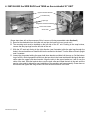
COMMERCIAL COOKING APPLIANCES Model LPG-30 & LPG-60 Self-Contained Propane Fueled Outdoor Charbroiler Use and Care Instructions Model # _________________________ Serial # __________________________ Date: ___________________________ Retain this Manual for future reference MAGIKITCH’N P.O. BOX 501 CONCORD NH 03302-0501 509 ROUTE 3A BOW NH 03304 603-225-6684 FAX 603-225-8497 WWW.MAGIKITCHN.COM L25-003 Rev 4 (09/12) TABLE OF CONTENTS L25-003 Rev 4 (09/12) 1. Safety Information 1 2. Charbroiler Assembly and Installation 4 3. Assembly Diagram 5 4. Installing the Side Rack & Propane Tank on a 30” Unit 6 5. Connecting the Gas Lines to the Propane Tanks 7 6. Operating, Lighting and Cleaning Instructions 8 7. Burner and Orifice Inspection 9 8. Charbroiler Illustration and Parts List 10 9. Tank Rack Illustration and Parts List 12 10. Options 12 11. Warranty 13 1. SAFETY INFORMATION Safety instructions should be obtained from your local gas supplier and posted in a prominent location near the area of operation. These instructions are to be followed in the event of a gas leak. FOR YOUR SAFETY Do not store or use gasoline or other flammable vapors or liquids in the vicinity of this or any other appliance. WARNING Improper installation, adjustment, alteration, service or maintenance can cause property damage, injury or death. Read the installation, operating and maintenance instructions thoroughly before installing or servicing this equipment. This unit shall only be operated outdoors. This commercial appliance must only be operated by adults. The area of operation must be free and clear of all combustible material. Never obstruct the flow of combustion and ventilation air into or out of this unit. Always lock the caster brakes to prevent movement while the appliance is in use. On the side of the caster, press downward the ‘ON’ pad to apply the brake and on the ‘OFF’ pad to release it. Allow adequate clearance for air openings into the combustion chamber of this unit. Units may be operated with 0” minimum clearance to non-combustible construction in areas that are non-combustible locations. Unit is not approved for installations in combustible constructions. L25-003 Rev 4 (09/12) 1 1. SAFETY INFORMATION (continued) Unit intended for mobile, non-permanent installation only. Adequate clearances (minimum of 3’) in front of the unit for servicing and proper operation must be maintained. Use only the legs and casters supplied with unit. Do not block the front or sides of unit. Check periodically to insure that the burners are fitted properly on the orifices (see burner/orifice inspection figure 9, Page 9), or when there is a performance problem. Inspect the flexible gas hose(s) prior to each use. If it is evident that there is excessive abrasion or wear, or the hose is cracked or damaged, it must be replaced before the appliance is put into operation. The replacement hose assembly shall be that specified by the manufacturer. Fuel cylinders used with the tank rack for this appliance must be constructed and marked in accordance with the specifications for propane cylinders of the U.S. Department of Transportation (DOT), or CAN/CSA B339. Such cylinders must be 20-pound vertical type, 12” in diameter and 18” in length, have a shutoff valve and a Type I, QCC1 service outlet connection. They must have a safety relief device that communicates directly with the vapor space of the cylinder. They must have a system arranged to withdraw vapor only in the vertical position. The tank or cylinder must have a collar to protect the service valve from physical damage. This unit is for outdoor use only, in a well ventilated space! Do not operate this unit in a building, garage or any other enclosed area. Propane cylinders must be safely secured during transit and oriented in accordance with instructions and warnings marked on the cylinders. Do not allow cylinders to remain in areas of high heat, such as a closed car, trunk, or in direct sunlight. Consult instructions and warnings marked on the cylinders. When the unit is not in use, the gas must be shut off at the supply cylinder(s). Storage of the appliance indoors is only permissible if the propane cylinders are disconnected from the appliance and left outdoors. Propane cylinders must be stored outdoors in a well ventilated area out of the reach of children. Disconnected cylinders must not be stored in a building, garage or any other enclosed area and must have protective dust caps installed over the outlet openings. The pressure regulator and gas hose assembly supplied with unit must be used. Use only replacement parts specified by the manufacturer. The handling, filling, use, storage and transportation of all sizes of LP gas cylinders must be in accordance with NFPA 58, Storage and Handling of LP Gases, or CAN/CGA B149.2, Propane Gas Installation Code. If your two-stage pressure regulator(s) are furnished with vent shields, they must be in place when the appliance is in use. The minimum ambient temperature for proper operation of this appliance is 50°F (10°C). L25-003 Rev 4 (09/12) 2 1. SAFETY INFORMATION (continued) Caution: The gas pressure regulator(s) provided with this appliance must be used. The regulator is set for an outlet pressure of 10 inches water column. Do not locate this appliance under overhead unprotected combustible surfaces. Do not allow dirt or foreign material to get into the gas line connectors when they are not attached to the fuel supply system. If the burners or runner tubes fail to light or remain lit, discontinue use of the unit. Shut off the unit and the gas supply and disconnect it. Have the unit checked and serviced, if necessary, before use again. If you smell gas, discontinue use of the unit and shut off the gas supply. Have a qualified person determine if there is a gas leak and have it repaired before operating the unit again. Propane gas is highly flammable and heavier than air. Treat it with the caution and respect it deserves. Surfaces of unit will become hot during normal operation and can cause burns and/or serious injury. Do not touch a hot unit without protective clothing. Allow the unit to cool before cleaning or disassembling. Do not use in high wind conditions. High winds may adversely affect burner performance. Use caution when rolling a charbroiler with loaded tank rack(s) over anything other than smooth terrain. Careless handling or excess speed could dislodge the tank causing equipment damage and/or personal injury. For installation or maintenance, contact your local dealer or the Authorized Service And Parts (ASAP) network. Installation or service by other than MagiKitch’n authorized service agencies or personnel may void warranty coverage. Consult the complete ASAP directory included with this manual, visit our website at magikitchn.com or call MagiKitch’n at 1-603-225-6684. L25-003 Rev 4 (09/12) 3 2. CHARBROILER ASSEMBLY and INSTALLATION These unassembled parts should be included in your charbroiler package (Figure 1): Item Number 1 2 6 8 9 10 25 Description Cooking Grid (s) Radiants Frame Assembly Runner Tube Cover(s) Water Tub(s) Base Leg & Swivel Lock Caster Assemblies ASSEMBLY INSTRUCTIONS (Refer to Figures 1 & 10, and Table 1) 1. Remove shipping bands from carton. 2. Remove top of carton. 3. Remove cooking grids(s), (1) from unit and set aside. 4. Remove and unwrap any small parts packages that are located inside beneath the cooking grid. NOTE: Parts made of stainless steel may be coated with a protective plastic film that must be removed before firing. 5. Lift frame assembly (6) from carton and set aside. 6. Lift water tub(s) (9) from carton and set aside. 7. Lift base (10) from carton and place upside down on ground. 8. Go to Section 4 or 5, on page 6, and mount the side tank rack(s) to the base unit. Then return to step 9 below. 9. Flip the base over, with the leg & caster assemblies installed, into the upright position. On a 30” appliance, the front of the base unit has the tank rack on the left side (See Figure 5). 10. Place the frame assembly (6) on base (10) with the shelf support brackets located in the notches on the front base assembly. 11. Place runner tube cover(s) (8) on their brackets to cover the runner tube(s). 12. Place the radiants (2) on their front and rear support pins over each burner. 13. Slide water tub(s) (9) into frame assembly (6). 14. Place cooking grid(s) (1) into frame assembly (6). L25-003 Rev 4 (09/12) 4 3. ASSEMBLY DIAGRAM Figure 1 L25-003 Rev 4 (09/12) 5 4. INSTALLING the SIDE RACK and TANK on the residential 30” UNIT Upper hold down bracket Tank rack body Pipe legs Regulator and hose assembly Lower tank bracket 20 lb. Tank (Some steps here will not be necessary if this is a new unit being assembled under Section 2) A. Remove the charbroiler from the base unit and turn the base unit over to work on it. B. The mounting rack must be installed on the left side of the 30” unit. Pushing in the snap buttons, remove the two pipe legs from the left side of the unit. C. With the 30” tank rack facing in the right direction (see illustration) slide the pipe legs through the holes in the rack and then re-install them into the sockets in the base. Turn the base unit back upright onto it’s casters. D. Loosen the wing studs holding the upper hold down bracket and slide it all the way up. Set the bottom ring of a 20 lb. vertical propane fuel tank into the two slots in the lower tank bracket and push the tank collar under the upper hold down bracket. Align the slots in the upper bracket so it will fit over the collar of the tank. Slide the bracket down over the tank collar and rotate the tank in the rack until the service valve outlet is aligned for easy installation of the regulator and hose assembly. Press down on the bracket and tighten the wing screws. Be sure the tank is secure in the rack. L25-003 Rev 4 (09/12) 6 Upper hold down bracket Left side tank rack installed Right side tank rack installed Lower tank bracket Left side tank, regulator and hose assembly, installed Right side tank, regulator and hose assembly, installed Note the orientation of the hose assembly in each case CONNECTING the GAS LINES to the PROPANE TANKS A. New propane tanks are shipped empty with no pressure and must be purged of air and filled with propane per NPGA (National Propane Gas Association) recommendations prior to initial use. B. Tank rack(s) must be mounted to the charbroiler base (See tank rack instructions). C. Tank(s) must be mounted securely to the tank rack(s) (See tank rack instructions). D. Install the black plastic gas connector onto the external thread on the tank valve. Turn it clockwise and hand tighten. Leak Testing E. The plumbing must now be tested for gas leaks before use. Turn all propane tank, burner control and runner tube control valve(s) to the “off” position. Wet all gas line fittings and connectors with a solution of soapy water (or commercial leak disclosing liquid). Slowly open the propane tank valve(s) and look for bubbles or foam at any of the joints in the system. If a leak is found, close the tank valves immediately and call your local dealer, the ASAP agency or the manufacturer. F. If the gas connections are leak-free, the unit is ready to use. Follow the lighting instructions in Sect. 7. L25-003 Rev 4 (09/12) 7 7. OPERATION, LIGHTING and CLEANING Assemble unit per installation and assembly instructions. Fill water tubs to within ½” of top edges (this will control grease flare-ups, provide for ease of cleaning and keep cooked foods moist). Re-fill tubs with water when they evaporate to within ½” of the bottom of the tubs. Failure to keep water in the water tubs will lead to grease fires and will void the warranty. Lighting Instructions A. Check that the side tank racks are securely mounted on the unit. B. Open the cooking hood, if so equipped. Turn all the burner knobs and red runner tube knobs clockwise to the ‘off’ position, and slowly open the gas tank valves. C. Push & turn the runner tube knob(s) fully counter-clockwise to the ‘on’ position. Insert a lit match with the matchstick holder or a gas lighter flame through the oblong hole in the front panel. D. Check that the entire runner tube is lit by looking through the sight hole(s) located between the end burner knobs on the front panel. If the runner tube(s) will not light or stay lit, shut off the gas supply and do not use the unit. Wait 5 minutes before attempting to re-light the unit. E. After lighting the runner tube(s), open the desired burner valves and observe that the burners light completely from the runner tubes(s). Warning: If the burners or runner tube(s) fail to light or remain lit, shut off and disconnect the gas supply tank(s) and discontinue use of the unit. Call for service to correct the problem. NOTE: If the tank valves are not opened very slowly, an excess flow valve in the tank connector fitting (a safety feature) may restrict the flow of gas to the unit resulting in little or no flame at the burners. Should this happen, follow the shutdown instructions and be sure to shut off tanks and remove and re-attach the tank connectors as instructed. This is necessary to re-set a closed excess flow valve. Repeat steps A through E of the lighting instructions. The appliance should now function normally. Failure to follow these guidelines may cause the excess flow valve to restrict gas flow. Shutdown Instructions To shut down the unit, turn all burner and runner tube knobs clockwise to the ‘off’ position. Close gas tank valve(s), disconnect propane tank(s) and leave them outdoors. Figure 8 L25-003 Rev 4 (09/12) 8 Cleaning the Unit Clean the unit regularly after use. After removing from the unit, use warm soapy water and a stiff bristled brush or Cooking Top Grid: plastic pad. Cooking grid (top grid) must be removed to steam clean or pressure wash. Do not use steel wool or abrasive pads as they may degrade the metal finish. Radiants/Covers: These will need little or no cleaning due to high in-use temperatures. necessary, clean as for the cooking grid. Frame Assembly: Use warm, soapy water and a stiff bristle brush or plastic pad. Be careful not to get water into the burners or runner tubes. Do not pressure wash. Water Tubs/Base Assembly: If Clean as per top grid. 8. BURNER/ORIFICE INSPECTION A.) Remove the service shelf by removing the two screws at the ends (29). B.) Slide service shelf forward and then lift it off the unit. C.) The front of the burners, the valve bodies, and orifices are now exposed for inspection. Looking down into the unit, compare each assembly with the diagram below (Figure 9) for alignment. D.) If the components ARE NOT aligned as shown in the diagram, DISCONTINUE USE and contact the appliance manufacturer. E.) If they appear as in the diagram, carefully replace the service shelf and re-insert and tighten the screws. Your unit is ready for use. Figure 9 L25-003 Rev 4 (09/12) 9 9. CHARBROILER ILLUSTRATION Figure 10 L25-003 Rev 4 (09/12) 10 CHARBROILER PARTS LIST Item # 1 2 3 4 5 6 7 8 9 10 11 12 13 14 15 16 17 18 19 20 21 22 23 24 25 26 27 28 30 N/S 32 33 34 36 37 38 39 40 41 42 43 44 45 46 Description Cooking Top Grid, Heavy Duty Cooking Top Grid, Std (shown) Radiant Screw & Nut, ¼-20 x 1-1/2” Screw & Nut, ¼-20 x ½” Main Burner Frame Assembly Runner Tube Bracket Runner Tube Cover Water Tub Base Assembly Runner Tube, LH Runner Tube, RH Runner Supply Tube Fitting, 1/8 MPT X 3/16 C Fitting, 90º, 1/8 FPT X 3/16 C Plug, Pipe, 1/8 NPT Valve, Main Burner Gas Left Manifold Assembly Right Manifold Assembly Elbow, 90º street, ¼ NPT, BMI Reducing coupling, ¾ x 3/8 NPT Regulator, two-stage, LP gas Valve, Pilot Gas Knob, Runner Tube Valve Leg w/Swivel Locking Caster Outer Front Knob, Main Burner Valve Center Support Service Shelf, stainless Steel Pilot Box Ignition Control Matchstick Holder Nipple, 3/8 NPT x L, BMI Orifice, #55, Short Grease Baffle End Cap, LH End Cap, RH Hose assembly only, LP gas, 20” Elbow, 90º street, 3/8 NPT, brass QCC1 tank connector Trim, back (optional) Trim, LH side (optional) Trim, RH side (optional) Hose / regulator ass’y, LP gas 37” Regulator, Appliance, LP gas Qty 2 2 8 16 52 8 1 5 2 2 1 1 1 2 2 2 1 8 1 1 2 2 2 2 2 Set 1 8 1 1 1 1 2 8 1 1 1 2 2 2 1 1 1 2 2 LPG-60 Part No. 3912-0525300 3912-0280400 5403-0500301-C 4001-0485100/0485200 4001-0049600/0485200 3003-0486000 5208-0983104-C 5403-0500201-C 5403-0510302-C 5106-0297401-FA-C 5105-0487502-C 3006-0292500 3006-0513800 60119002 2908-0981300 2902-0871500 2909-0540200 2802-0877500 5201-0989103 5201-0989104 2904-0483800 60136001 2701-1133800 2802-0983900 3501-0983201 5207-1175101 5405-1169001-C 3501-1032301 5199-0871600-C 5425-1513802-C 7225-2000600-C 3699-1115100 0801-1168000 2908-0977300 5414-0485601-C 5425-1513901-C 5425-1513902-C 7201-1176401 2904-1158700 4102-1315500 5405-0906801-C 5405-0985601-C 5405-0985602-C 4199-1151600 2701-1133900 Table 1 L25-003 Rev 4 (09/12) 11 Qty 1 1 4 8 28 4 1 3 1 1 1 1 — 1 1 1 1 4 1 — 1 1 1 1 1 4 1 4 — 1 1 1 1 4 — 1 1 1 1 1 1 1 1 1 1 LPG-30 Part No. 3912-0525300 3912-0280400 5403-0500301-C 4001-0485100/0485200 4001-0049600/0485200 3003-0486000 5208-0983101-C 5403-0500201-C 5403-0510302-C 5106-0297401-FA-C 5105-0487501-C 3006-0292500 — 60119002 2908-0981300 2902-0871500 2909-0540200 2802-0877500 5201-0989103 — 2904-0483800 60136001 2701-1133800 2802-0983900 3501-0983201 5207-1175100-C 5405-1168901-C 3501-1032301 — 5425-1513801-C 7225-2000601-C 3699-1115100 0801-1167900 2908-0977300 — 5425-1513901-C 5425-1513902-C 7201-1176401 2904-1158700 4102-1315500 5405-0917601-C 5405-0985601-C 5405-0985602-C 4199-1151600 2701-1133900 10. TANK RACK ILLUSTRATION 00000100001 TANK RACK PARTS LIST Item # 1 2 3 4 5 LPG-30 Residential Qty Part No. 2 5299-1154900 1 5414-1117600 1 5414-1117800 1 5414-1117700 3 4001-0049600/0044100 Description Wing Stud & Stop Nut Upper Hold Down Bracket Tank Rack Body Lower Tank Bracket Keps Screw & Acorn Nut Table 2 11. OPTIONS Some optional accessories for your MagiCater Gas Charbroiler include: Stainless Steel Service Shelf — Durable, smooth working surface; matches the optional SS trim kit. MagiGriddle — Heavy polished steel griddle for cooking breakfasts, sautéing, etc. Steamer Set — Holds full-size hotel pans for steaming and warming. Cutting Board —Full length custom fitted Richlite cutting board fits over the service shelf. Split Hood — Twin roll-up hoods keeps heat in for roasting and broiling. Windguard — Keeps grill firing properly in windy conditions. Stainless Steel Trim Kit — For a sleek appearance and easy cleaning exterior. Slip-on Stainless Steel Service Shelf — Adds another full-size worktop space at the back. Heavy Duty Top Grid — For serious cooking workloads. Waterproof Slipcover — Durable custom fit cover that protects against dirt and weather damage. L25-003 Rev 4 (09/12) 12 12. WARRANTY: ORIGINAL EQUIPMENT WARRANTY (For U.S. and Canada) MagiKich’n warrants to each original Buyer that its electrically-heated or gas-fired charbroilers / outdoor grills will be free from defects in material and workmanship for the period specified below. MagiKitch’n’s obligation under this warranty shall be limited to replacing or repairing, at its option, any part found to be defective within the specified warranty period. PRODUCT WARRANTY PERIOD One (1) Year Limited Parts and Labor for Indoor Charbroilers and Outdoor Grills NOT WARRANTED: Accident to, misuse of, harsh chemical cleaners, or natural wear of this appliance. IMPORTANT: Any defective parts must be returned for replacement under this warranty. When writing, be sure to mention the serial number and model number appearing on the nameplate on the front of your equipment. MAGIKITCH’N P.O. BOX 501 CONCORD NH 03302-0501 509 ROUTE 3A BOW NH 03304 603-225-6684 FAX 603-225-8497 WWW.MAGIKITCHN.COM L25-003 Rev 4 (09/12) 13