1
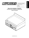
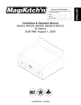
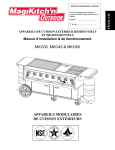
600 CE SERIES
GAS BROILER
INSTALLATION – OPERATION - MAINTENANCE
MAGIKITCH’N
P.O. BOX 501
CONCORD NH 03302-0501
509 ROUTE 3A
BOW NH 03304
603-225-6684
FAX 603-225-8497
WWW.MAGIKITCHN.COM
31-01-12962 rev B
L25-004 rev 1 (05/11)
IMPORTANT
INSTALLATION, SERVICING, OR CONVERSION OF THIS APPLIANCE
TO
BE
CARRIED
OUT
BY
QUALIFIED
SERVICE
TECHNICIANS/INSTALLERS IN CONFORMANCE WITH NATIONAL
AND LOCAL REGULATIONS.
WARNING: IMPROPER INSTALLATION, ADJUSTMENT, ALTERATION,
SERVICE OR MAINTENANCE CAN CAUSE PROPERTY DAMAGE,
INJURY OR DEATH. READ THE INSTALLATION, OPERATING AND
MAINTENANCE INSTRUCTIONS THOROUGHLY BEFORE INSTALLING
OR SERVICING THIS EQUIPMENT
INSTRUCTIONS TO BE FOLLOWED IN THE EVENT THE USER SMELLS
GAS MUST BE POSTED IN A PROMINENT LOCATION. THIS INFORMATION MAY BE OBTAINED BY CONTACTING YOUR LOCAL GAS
SUPPLIER.
FOR YOUR SAFETY
Do not store or use gasoline or other flammable vapors or liquids in the
vicinity of this or any other appliance.
The information contained in this manual is important for the proper
installation, use, and maintenance of this unit. Adherence to these
procedures and instructions will result in satisfactory grilling results
and long, trouble free service. Please read this manual carefully and
retain it for future reference.
THIS APPLIANCE IS INTENDED FOR PROFESSIONAL USE BY QUALIFIED
PERSONNEL ONLY, NOT FOR INDIVIDUAL/HOME USE.
WARNING: Improper installation, adjustment, alteration,
service or maintenance can cause property damage, injury or
death. Read the installation, operating and maintenance
instructions thoroughly before installing or servicing this
equipment.
1-01-12962 rev B L25-004 rev 1 (05/11)
2
For installation or maintenance, contact your local dealer or authorized service
agent. Installation or service by other than MagiKitch’n authorized service agencies
or personnel may void warranty coverage. Call Pitco Frialator Technical Support at
603-225-6684 who will put you in touch with the proper local service organization or
make service arrangements for you.
Installation
Delivery and Location
Broiler Assembly
Gas Connection and Conversion
Operation
Broiler Set Up
Lighting Instructions
General Charbroiling Tips
Maintenance
Cleaning and Preventative Maintenance
Accessory and Replacement Parts List
1-01-12962 rev B L25-004 rev 1 (05/11)
4
Installation
Delivery and Location
DELIVERY
Each broiler was carefully inspected and packaged before
being tendered to the carrier. Upon delivery of your new
broiler:
• Uncrate the broiler and check for damage. Most
carriers will accept claims for damage if they are
notified within seven days of delivery and the shipping
container is retained for inspection.
NOTE: The broiler top grid is shipped underneath the
unit. Be sure to remove it before disposing of the
packing crate.
MagiKitch’n cannot assume responsibility for loss or
damage suffered in transit. The carrier assumed full
responsibility for delivery in good order when the
shipment was accepted.
31-01-12962 rev B L25-004 rev 1 (05/11)
LOCATION
• Place the unit in a properly ventilated area.
• Keep the area free and clear of all combustibles such
as paper, cardboard, and flammable liquids and
solvents.
• This unit requires 0cm minimum clearance to non–
combustible construction. The unit is not approved for
installation in areas with combustible construction.
• Provisions must be made for an adequate air supply to
the broiler.
• Keep the area in front of the unit free from
obstructions that could block the flow of combustion
and ventilation air.
• Be sure there is sufficient clearance at the rear of the
unit for gas connections, regulator and any master
shutoff valve(s) to be installed.
• The location must provide adequate clearance for
servicing.
Before making any gas connections to this broiler, check
that the available gas supply meets the requirements for
supply pressure and gas type shown on the rating plate on
the front of the unit.
1
Installation
Broiler Assembly
NOTE: This appliance shall be installed in accordance CASTER INSTALLATION
with current regulations and used only in a well–
ventilated space. Refer to these instructions before A flexible hose/connector must be used on any broiler
installed on casters. The connector must meet National and
installing and using this appliance.
Local codes.
NOTE: Installation and connection must be performed by
A restraint must be used to limit the movement of the
a qualified installer only.
appliance. Limited movement cannot depend on the
COUNTERTOP MODELS
flexible connector. DO NOT attach the restraint to gas
Countertop models must be sealed to the counter surface in piping or electrical conduit!
compliance with National and Local Sanitation standards.
1. Apply a 13mm bead of silicone to the bottom of the
broiler. The silicone should run approximately 6mm
from the front, back and side edges of the unit.
LEG ATTACHMENT
1.
The 15 cm legs are packed in the top section of the broiler.
1. Screw the legs into the threaded holes in the corners
on the bottom of the broiler.
2.
2. Place the broiler onto the legs.
3. Turn the adjustable leg feet to level the oven.
WARNING!!
If the restraint is disconnected for any reason it
must be reconnected when the unit is returned to
its original position.
Screw the casters into the threaded holes in the corners
on the bottom of the broiler.
NOTE: The locking casters must be installed on the
front of the broiler.
Place the broiler onto the casters.
Figure 2
Figure 1
Non-locking
Caster
1-01-12962 rev B L25-004 rev 1 (05/11)
Locking
Caster
2
Installation
GAS CONNECTION
GAS CONVERSION
An adequate gas supply is required for proper broiler
performance. With all burners on “HIGH”, the manifold
pressure should not show any appreciable drop.
Fluctuations of more than 25% will create pilot problems
and affect burner operation.
All units are shipped with the appropriate orifices and
components required for the gas requested. If the unit
does not perform well or has unsatisfactory flame
characteristics (too high, yellow tips, lifting), check that
the supply pressure and orifice size are appropriate for
the gas used before making any adjustments.
WARNING!!
This unit must be connected ONLY to the type
of gas specified on the rating plate.
Remove the hairpin clips securing the burners. This
will allow for removal of the burners for inspection,
cleaning and servicing.
Attach the regulator supplied with the unit. The
regulator must be installed at the entry end of the gas
manifold.
Use the following directions to convert the unit to a
different type of gas if necessary. Each conversion kit
contains all the orifice sizes and markings required for
converting any size unit to any gas type in all countries.
Note that in Belgium units may not be converted. For
some conversions it may also be necessary to replace the
regulator or restrictor orifice.
1.
2.
3.
4.
5.
6.
NOTE: Be sure the regulator is installed so that the
gas flows in the same direction as the
arrow on the bottom of the regulator. Use
the supplied regulator only. Use of any
other regulator will invalidate the
warranty.
Adjust the regulator to the burner pressure listed on
the rating plate. Refer to the table on the following
page for proper pressure settings.
NOTE: A pressure regulator is not required for all
countries.
Use pipe joint compound suitable for use with LP
gas on all threaded connections.
Turn off all burner valves.
Turn on the gas supply. Check all connections for
gas leaks using soap and water. Never use an open
flame to check for gas leaks!
(05/11)
rev 01 5-2001
1
31-01-12962 rev B L25-004 rev
NOTE: Refer to the table on the following page to
determine gas requirements, pressure settings
and orifice sizes.
1. Shut off the gas supply to the unit.
2. Disconnect the unit from the gas supply.
3. Remove the top grids, radiants, runner tubes and
burners.
4. Remove the brass runner tube orifice. Replace with
the new orifice.
5. Remove all burner orifices. Replace with the new
orifices.
6. Adjust the air shutters on all the burners to the
correct opening. Mark the air shutter at the correct
setting. Re-install the burners.
7. Re-install the runner tubes, radiants, and top grids.
8. Adjust the regulator to the correct gas pressure. If a
restrictor orifice is required in place of the regulator
to meet your countries specific codes, remove the
old restrictor orifice and replace it with a new one
correctly sized to provide the burner pressure
specified for the gas type being used.
9. Adhere the appropriate conversion sticker to the
front of the unit, near the rating plate.
3
Operation
Gas Connection and Conversion Information for 600-CE Model Broilers
Country
NL
Appliance
Category
II2L3B/P
FR
II2L3P
I2E+
I3+
II2E+3+
DE
II2ELL3B/P
GB
II2H3P
IT
II2H3+
ES
II2H3+
PT
II2H3+
SE
II2H3B/P
DK
II2H3B/P
FI
II2H3B/P
AT
II2H3B/P
NO
IE
I3B/P
II2H3P
GR
II2H3B/P
LU
II2E3B/P
BE
Gas
Category
2L
3B/P
3P
2E+
3+
2E+
3+
2ELL
3B/P
2H
3P
2H
3+
2H
3+
2H
3+
2H
3B/P
2H
3B/P
2H
3B/P
2H
3B/P
3B/P
2H
3P
2H
3B/P
2E
3B/P
Runner Tube Orifice (mm)
Gas
Type
624/648
630/660
G20
G25
G30
G31
0.87
0.87
0.52
0.52
0.98
0.98
0.58
0.58
Gas
Type
G25
G30
G31
G20/25
G30/31
G20/25
G30/31
G20/25
G30
G20
G31
G20
G30/31
G20
G30/31
G20
G30/31
G20
G30
G20
G30
G20
G30
G20
G30
G30
G20
G31
G20
G30
G20
G30
Supply
Pressure
(mb)
25
30
50
20/25
30-37
20/25
30-37
20
50
20
50
20
30-37
20
30-37
20
30-37
20
30
20
30
20
30
20
50
30
20
50
20
50
20
50
Burner
Pressure
(mb)
10.7
29.5
36.5
16.6/20.6
29.5-36.5
16.6/20.6
29.5-36.5
16.6-10.7
29.5
16.6
36.5
16.6
29.5-36.5
16.6
29.5-36.5
16.6
29.5-36.5
16.6
29.5
16.6
29.5
16.6
29.5
16.6
29.5
29.5
16.6
36.5
16.6
29.5
16.6
29.5
open
open
open
9.0
open
9.0
open
9.O-open
open
9.0
open
9.0
open
9.0
open
9.0
open
9.0
open
9.0
open
9.0
open
9.0
open
open
9.0
open
9.0
open
9.0
open
1.065
1.065
0.63
0.63
630
636
648
660
Hs
Hi
25.2
22.7
29.3
26.4
41.1
37.1
50.1
45.2
1-01-12962 rev B L25-004 rev 1 (05/11)
1.85
1.02
1.02
1.5
1.02
1.5
1.02
1.5-1.85
1.02
1.5
1.02
1.5
1.02
1.5
1.02
1.5
1.02
1.5
1.02
1.5
1.02
1.5
1.02
1.5
1.02
1.02
1.5
1.02
1.5
1.02
1.5
1.02
Air
Shutter
(mm)
636/672
Heat Input (kW)
624
16.5
14.9
Main
Burner
(mm)
4
Operation
Broiler Set Up
Top Cooking Grid
Radiants and Grease Shield
The radiants must be in place prior to operating the unit.
The radiants provide protection for the burners, create a
surface for the flare–up required for charbroiling and
provide radiant heat to the product.
The cooking grid has two positions, flat or tilted.
Water Tubs
• To place the grid in the tilted position, push down on
the grid handle and pull forward to engage the grid
hook.
• To place the grid in the flat position, pull up on the
grid handle and push back to disengage the grid hook.
When broiling, the grid must be in the tilted position.
This allows some of the grease to drain into the front
trough, reducing both smoke and flare–up. The flat
position should only be used to heat soups, sauces, etc.
DO NOT use the flat position for broiling.
The tubs are designed to reduce flare–up and eliminate
flash back. Any flaming grease that drips down is
extinguished when it hits the water. The tubs should be ¾
full of water. NEVER allow the water tubs to run dry.
NOTE: After initial installation, the unit must be
thoroughly cleaned prior to operation. Refer to
the Maintenance section of this manual for
cleaning instructions.
Grease Box
The majority of the grease will travel down the front
trough and into the grease box. The grease box must be
in place while operating the unit
.
Radiant
Grid Hook
Top Cooking Grid
Top Grid
Tilt Block
Side View of Top Grid
In tilt position
Grease Box
Right Water Tub
Left Water Tub
Figure 3
31-01-12962 rev B L25-004 rev 1 (05/11)
5
Operation
Lighting Instructions
1.
2.
3.
4.
5.
Turn all burners to OFF.
Remove the top grid.
Remove the last radiant on the right.
Turn the shut off valve to ON.
Press and hold the reset (blue) button on the safety
pilot valve. Wait 15–30 seconds. Light the runner
tube. DO NOT release the reset button.
NOTE: If the runner tube does not light, wait a few
seconds, then try again.
NOTE: When lighting the runner tube for the first
time after connecting the unit to the gas
source, the light time will probably increase
to 1–2 minutes.
6.
Wait an additional 15–30 seconds. Release the reset
button. The runner tube should remain lit.
NOTE: If the runner tube fails to ignite, repeat step
5. If the runner tube fails to ignite after
three attempts, contact an authorized
MagiKitch’n service agent.
7. Replace the radiant and top grid.
8. Push and turn the burner valves to operate the
individual burners as needed.
Broiler Shut Down
1. Turn the shut off valve to OFF.
2. Turn all burners to OFF.
Off
On
Top Grid
Shut-off
Valve
Radiant
Thermocouple
(located on far
end of runner tube)
Reset Button
Safety Pilot Valve
Safety Pilot Valve
(located under
shelf)
Figure 4
1-01-12962 rev B L25-004 rev 1 (05/11)
6
Operation
General Charbroiling Tips
PREHEATING
FLARE–UP
The broiler must be preheated before cooking. We
recommend a preheat time of 10-15 minutes. After
preheating, the broiler will be hot enough to cook on
without sticking and will produce the proper searing
effect.
In charbroiling, a certain amount of flare–up is desirable
in order to flavor the product. However, excess flare–up
burns product and leaves a bitter taste. Generally, flare–
up increases with the heat of the broiler and the fat
content of the product.
COOK ZONES
There are three separate cooking zones on your
MagiKitch’n charbroiler:
• The front 1/3 of the broiler is the coolest section.
• The center 1/3 of the broiler has medium heat.
• The rear 1/3 of the broiler is the hottest. (even though
it is the farthest from the burner in the tilt position)
The three cook zones enable more efficient cooking
without flame adjustment. It is possible to cook a rare,
medium and well done steak in the same amount of time
simply by placing the product in different cook zones.
The cooking process can also be slowed or increased by
moving product between zones.
31-01-12962 rev B L25-004 rev 1 (05/11)
Heat
Product Fat Content
High
Low
High
High Flare–up
Moderate
Low
Moderate
Low Flare–up
The cook zones can be used to advantage during peak
periods. High fat product can be cooked in the cool front
section, while lean product is placed on the hotter rear
section. This allows for better control of flare–up and
product quality.
7
Operation
General Charbroiling Tips
MARKING PRODUCT
1. Place the product diagonally on the back 1/3 of a
clean broiler grid.
2.
NOTE: For white fleshed product (chicken, fish) be
sure Marking product to baste the product
and brush the grid with pure vegetable oil.
When the product is marked, rotate it ¼ turn to
provide the diamond pattern.
NOTE: This step can be eliminated if only one line
is desired.
Rear of Broiler
3.
When the diamond mark is achieved, turn the food
over and move to the middle cook zone to finish
broiling. DO NOT turn the food over to the marked
side or the pattern will be marred.
NOTE: For thicker and well done products, move
the product to the front cook zone.
4.
NOTE: Check the internal product temperature on
the unmarked side.
Serve the food with the pattern facing up.
Rear of Broiler
Rear of Broiler
Hot
Hot
Medium
Medium
Cool
Cool
Front of Broiler
Front of Broiler
Front of Broiler
Step 1
Step 2
Step 3
Figure 5
1-01-12962 rev B L25-004 rev 1 (05/11)
8
Maintenance
Cleaning and Preventative Maintenance
Proper maintenance of your broiler will prolong the life
of the appliance and ensure proper performance.
DAILY CLEANING
Top Grid
1. Remove the grid.
2. Use the MagiKitch’n scraper to remove any cooking
debris from the rods, especially the underside.
3. Clean the frame including the tubes and angles on
the sides, front and back with steel wool.
Cabinet, Shelves, Water Tubs, and Grease Boxes
These parts are stainless steel and can be cleaned with
any non–toxic industrial stainless steel cleaner.
1. Apply cleaners when the broiler is cold. Always rub
with the grain of the metal.
Water Tubs
Empty the excess grease and water. Wipe the tubs clean.
ANNUAL MAINTENANCE AND INSPECTION
The unit should be inspected annually by a qualified gas
appliance service personnel.
The main burner valves should be greased annually, or as
necessary, to maintain smooth operation and prevent gas
leakage.
1. Remove the knobs from the front of the unit.
2. Remove the outer front panel.
3. Loosen the two screws securing the collar to each
valve.
4. Carefully disassembly the valves. See Figure 6.
5. Clean all parts.
6. Apply high temperature valve grease to the rotor
assembly.
7.
NOTE: The valve grease must be suitable for all
gas types.
Reassemble the valves and broiler.
Grease Box
The grease box should be emptied daily.
WEEKLY CLEANING
Soak the top grid in a degreasing solution. The grid will
need to be re–seasoned after soaking.
Orifice
Body
Rotor
Spring
Stem
Collar
Figure 6
31-01-12962 rev B L25-004 rev 1 (05/11)
9
Maintenance
Accessory and Replacement Parts List
NOTE: This is a partial parts list for parts not shown here, call MagiKitch’n or a MagiKitch’n service representative.
Always give the Model and Serial Numbers of your unit when ordering parts and accessories.
Item
Description
Item
Description
1
Top grid
2
Radiant
26
Valve (push to turn)
3
Burner
27
Pressure tap orifice
4
Burner clip
28
Heat shield
5
Baffle, right side
29
6
Baffle, left side
30
Manifold, weld assembly
7
Outer side
31
Outer front
8
Inner side (right)
32
Knob
9
Inner side (left)
33
Grease trough
10
Drip cup
34
Service shelf
11
Outer back
35
Service shelf support
12
Inner back
36
Thermocouple (not shown)
13
Rear support angle
37
Thermocouple bracket (not shown)
14
Rear burner support
38
15
Water tub
39
16
Grease trough
40
17
Towel bar
41
½” NPT Jam nut
18
Lower shelf
42
½” FNPT Shut off valve
19
Upper shelf
43
½” NPT nipple
20
Base assembly
44
¾” MNPT x ½” FNPT adaptor
21
Upper shelf
45
180° return elbow
22
Inlet manifold
46
¾” close nipple
23
Runner tube
47
Safety pilot valve
24
Inner front assembly
48
Runner supply tube
25
90° elbow with clip
49
1-01-12962 rev B L25-004 rev 1 (05/11)
10
Maintenance
Figure 7
31-01-12962 rev B L25-004 rev
rev01 5-2001
(05/11)
11
SMB
600 SERIES-CE
GAS BROILER
MODEL SPECIFIC INSTRUCTIONS
MAGIKITCH’N
P.O. BOX 501
CONCORD NH 03302-0501
509 MAGIKITCH’N
ROUTE 3A
A MAYTAG
COMPANY
BOW
NH 03304
800-258-3708
180 Penn Am Drive
Quakertown, Pennsylvania 18951-2435 USA
Telepho603-225-6684
ne 800-441-1492 Fax: (215) 538-3644
FAX 603-225-8497
WEBSITE:
WWW.MAGIKITCHN.COM
WWW.BLODGETTCORP.COM
© 2000– MagiKitch’n
31-01-12962 rev B L25-004 rev 1 (05/11)
12
Table of Contents
1. Lighting Instructions
2. Initial Set Up
3. SMB 600 Series Illustration
4. Accessories and Parts List
31-01-12962 rev B L25-004 rev 1 (05/11)
13
1. LIGHTING INSTRUCTIONS
SMB 600 Series -CE Models with safety pilot
1.
2.
3.
4.
Turn all burners to OFF.
Remove the top grid.
Turn the shut off valve to ON.
Press and hold the reset (blue) button on the safety pilot valve. Wait 15–30 seconds. Light the runner tube.
DO NOT release the reset button.
NOTE: If the runner tube does not light, wait a few seconds, then try again.
NOTE: When lighting the runner tube for the first time after connecting the unit to the gas source, the light time
will probably increase to 1–2 minutes.
5. Wait an additional 15–30 seconds. Release the reset button. The runner tube should remain lit.
NOTE: If the runner tube fails to ignite, repeat step 5. If the runner tube fails to ignite after three attempts,
contact an authorized MagiKitch’n service agent.
5. Replace the top grid.
6. Push and turn the burner valves to operate the individual burners as needed.
Broiler Shut Down
1.
Turn the shut off valve to OFF.
2.
Turn all burners to OFF.
31-01-12962 rev B L25-004 rev 1 (05/11)
15
SMB 600 Series -CE Models with safety pilot
2. INITIAL SET-UP
SMB 600 Series-CE models
COAL SUPPORT - The coal support must be installed so that it is pushed against the back wall
of the unit. This creates an air gap over the runner tube to allow proper ventilation.
COALS - Use only Magicoals supplied by MagiKitch’n. Do not use lava rock or other replacement
coals. They do not perform as well or last as long as the Magicoals that were designed for this
application. Place the coals evenly across the surface of the coal support. Do not pile them up.
This will cause excessive flare up, reduce ventilation, and cause overheating of the valves and
other components.
PREHEATING - It is necessary to preheat a cold broiler each time before cooking. The recommended time is 15-20 minutes for
coal style charbroilers, at which time the cooking grid should be hot enough to cook on without sticking, and will produce the
proper searing effect.
31-01-12962 rev B L25-004 rev 1 (05/11)
16
3.
TYPICAL SMB 600 SERIES ILLUSTRATION
(Model SMB 636 shown)
Note: Your unit may vary from this typical diagram.
31-01-12962 rev B L25-004 rev 1 (05/11)
17
4.
ACCESSORY / PARTS LIST FOR SMB 600 SERIES MODELS
Not all parts are illustrated, nor are all parts are listed. If you need a part that is not listed here, call MagiKitch’n for a quote. Always
have your model and unit serial numbers available when phoning or ordering.
THESE PARTS SOLD THRU OUR DEALER NETWORK ONLY.
Ref. No.
Description
Ref. No.
Description
1
Top Grid, Standard
23
Gas valve, main burner
2
Radiant
24
Gas valve,runner tube (not shown)
3
Burner
25
Orifice, main burners (not shown)
4
Burner retaining clip (not shown)
26
Orifice, runner tube (not shown)
5
Runner tube (not shown)
27
Manifold assembly (not shown)
6
Water Tub, Left Hand
28
Manifold heat shield
7
Water Tub, Right Hand
29
Inner heat shield (not shown)
8
Grease Box
30
Inner front (not shown)
9
Leg, 6” (not shown)
31
Front burner support
10
Caster, 6” (not shown)
32
Outer side
11
Knob, main burner
33
Inner side
12
Knob, runner tube
34
Side baffle
13
Scraper (not shown)
35
Side baffle support (not shown)
14
Brush (not shown)
36
Top grid center support (not shown)
(48/60/72 only)
15
Regulator
37
Outer back (not shown)
16
Utility bar
38
Inner back
17
Service shelf
39
Back stiffener (not shown)
18
Service shelf support (not shown)
40
Back splash liner
19
LH Frame mtg brkt (not shown)
41
Rear burner support
20
RH Frame mtg brkt (not shown)
42
Shelf
21
Grease trough
43
Inner bottom (FM only, not shown)
22
Outer front
44
Outer bottom (not shown)
45
Coal Rack
46
Coals
31-01-12962 rev B L25-004 rev 1 (05/11)
18
Original Equipment Limited Warranty
MagiKitch'n appliances are designed to give you long and satisfactory service if
installed and operated in accordance with our instructions. We warrant this appliance
against defective workmanship and material for one year form installation or 15
months from ship date, and agree to replace free of charge and defective parts or
equipment returned to us. This warranty does include travel time not to exceed 2
hours and mileage not to exceed 50 miles.
WARRANTY LIMITATIONS OR EXCLUSIONS :
Radiants and coal support are warranted for 6 months only.
Accidental damage, misuse, harsh cleaning chemical usage, and normal
wear of this appliance are not warranted.
Conversion or adjusting of gas components (i.e.; pilots, orifices, burners, valves or
regulators) unless duly authorized by MagiKitch’n or it’s ASAP agent.
Not Warranted:
Accident to, misuse of, harsh chemical cleaners, or natural wear of this
appliance.
Conversion or adjusting of gas components (i.e.; pilots, orifices, burners, valves
or regulators).
IMPORTANT: DO NOT destroy any defective part – it must be returned for
replacement under this warranty.
When writing, be sure to mention the Serial Number and Model Number appearing on
the nameplate on the front of your equipment.
Keep for your records
This Warranty cannot protect you unless your MagiKitch’n appliance is registered at the factory.
For your own protection, mail the attached card WITHIN TEN DAYS after this appliance has been
installed, or the WARRANTY WILL BE VOID.
MAGIKITCH’N
P.O. BOX 501
CONCORD NH 03302-0501
509 ROUTE 3A
BOW NH 03304
603-225-6684
FAX 603-225-8497
WWW.MAGIKITCHN.COM
31-01-12962 rev B L25-004 rev 1 (05/11)
19