Download Bacharach MZ-RD Instruction manual
Transcript
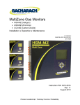
MultiZone Gas Monitors
x HGM-MZ
x AGM-MZ
x CO2-MZ
(Halogen)
(Ammonia)
(Carbon Dioxide)
Instruction 3015-5074
Installation / Operation / Maintenance
Rev. 9 – December 2011
UL 61010-1
CAN/CSA 22.2 No. 61010.1
EN 14624
Multi-Zone Gas Monitors
WARRANTY
!"#!##"#
""#!#"’s ap#.
Bacharach’’"! " "
Bacharach’####"#ture and
shown to Bacharach Inc.’##$!#
#!!%&'# #
#
!!’
’"! #""##
#"###
! #( that )
"#-#*"%#'
+,8),9);9<==;,=,,>?
@D,=;F=,9D,;=;F=??,,F;
,@)8%'
=;H=;F=
)+,<==;,,>,)J
,F;?
@F;9<+)@
J=);
+,J
,F<==;,)8J,?+=;=
H=;F8;,8)==?@
=
@),K=;F%'=;H)
9=);
=
H9+?
=J),J,FH;?);=?)
)<+,+,);)=;98)JB=?+==?+QS ;,9
9,;?,=?@=
)J
,F
"#"*#
"includ!"tion incidental or consequen";"
*#!""!
!R###
Register your warranty by visiting
www.MyBacharach.com
"""$## #"
""!
##nT"
in conn!##"#"
Patent VWXVX
?Y&XXX–&X((=
;#""!ut the
prior written #
®
=?+==?+ "[#="["
"[#!
ii
P/N: 3015-5074 Multi-Zone Gas Monitors
Table of Contents
SECTION 1. INTRODUCTION..................................................................................................................... 1
1.1.
1.2.
1.3.
1.4.
1.5.
1.6.
=J .............................................................................................................................. 1
<? ....................................................................................................................... 1
# .............................................................................................................................. 1
1.3.1. +R= .................................................................................................................... 1
1.3.2. ?"8""9 ...................................................................................... 2
1.3.3. =?! ................................................................................................................... 2
1.3.4. 9.............................................................................................................. 2
1.3.5. ,*="............................................................................................................ 2
1.3.6. ,*D ......................................................................................................... 2
1.3.7. =#J ...................................................................................... 2
1.3.8. JJ#" ........................................................................... 3
(] ?#J#............................................................................................................ 3
1.3.10. 8 ..................................................................................................................................... 3
1.3.11. ?............................................................................................................... 3
1.3.12. =
" ........................................................................................................................... 3
1.3.13. ? ................................................................................................................................. 3
^,*+!?" .................................................................................................. 4
8)! ............................................................................................................................ 4
1.5.1. 9F................................................................................................................ 4
1.5.2. ?"") ....................................................................................................... 5
1.5.3. @J
........................................................................................... 5
1.5.4. #J#%+9J)' .......................................... 5
1.5.5. #" ................................................................................ 5
1.5.6. "F%)' ................................................................................... 6
# ...................................................................................................................................... 7
SECTION 2. INSTALLATION ...................................................................................................................... 9
2.1.
2.2.
2.3.
2.4.
2.5.
2.6.
2.7.
2.8.
Installation Considerations .................................................................................................................. 2.1.1. <? .......................................................................................................... 2.1.2. Inspection ............................................................................................................................... 2.1.3. #J ........................................................................................................... 2.1.4. Moun ............................................................................................................. ?9"
.......................................................................................................... 10
2.2.1. )!............................................................................................................................... 10
2.2.2. ? ......................................................................................................... 11
2.2.3. ?
......................................................................................................... 11
2.2.4. ?,*
..................................................................................................... 11
2.2.5. ?"[
......................................................................................... 11
2.2.6. )^ .......................................................................................... 12
2.2.7. ?< .................................................................................................. 12
?" .......................................................................................................................... 13
,< ................................................................................................................................. 13
??""F .............................................................................................. 15
2.5.1. "FJ%F'? ........................................................................... 15
2.5.2. !J"" .................................................................. 15
2.5.3. " ................................................................................................... 15
2.5.4. ?"! .................................................................................. 16
2.5.5. ?" .............................................................................................................. 16
"JJ ........................................................................................................... 17
?J"" ................................................................................ 17
?#! ...................................................................................................................................... 18
2.8.1. Operation .............................................................................................................................. 18
P/N: 3015-5074 iii
Multi-Zone Gas Monitors
2.8.2. " ............................................................................................ 20
2.8.3. F ........................................................................................................................... 20
2.8.4. ?,;F*8J#,*8 .................................................. 20
2.8.5. ................................................................................ 20
2.8.6. @
............................................................................................................... 20
& )?
# ...................................................................................................... 21
&( Optional 4–20 "=F?) ............................................................................................. 21
&& 4-20 "=F??..................................................................................................... 22
2.10. ?,*=" .............................................................................................................. 23
2.10.1. )!............................................................................................................................... 23
2.10.2. Connection ........................................................................................................................... 23
SECTION 3. SETUP PROGRAMMING ..................................................................................................... 25
3.1.
3.2.
3.3.
3.4.
3.5.
3.6.
3.7.
Initial Power Up ................................................................................................................................. 25
FF .......................................................................................................................... 25
;( ................................................................................................... 25
;&Setup Screen ................................................................................................. 25
3.4.1. Location ................................................................................................................................ 26
3.4.2. ;"#_ ................................................................................................... 26
3.4.3. ="=[!J.................................................................................................... 26
3.4.4. ==" ....................................................................................................................... 26
3.4.5. _+ ............................................................................................................................. 27
3.4.6. F
" ...................................................................................................................... 27
3.4.8. Loop Mode ........................................................................................................................... 27
3.4.7. &8 ........................................................................................................................ 27
]` -Zero Mode ...................................................................................................................... 28
;] .................................................................................................. 28
3.5.1. )!............................................................................................................................... 28
3.5.2. ............................................................................................................................ 28
3.5.3. Node Address ....................................................................................................................... 28
3.5.4. Password .............................................................................................................................. 28
=8 .............................................................................................................. &
3.6.1. " ................................................................................................................... &
3.6.2. F,F .......................................................................................................................... &
3.6.3. Node Address ....................................................................................................................... 30
3.6.4. "?##%88@)' .................................................... 30
3.6.5. Password .............................................................................................................................. 30
3.6.6. =T"?##%88@)' ................................................. 30
3.6.7. F .............................................................................................................................. 30
,?)2 Sensor Baseline .............................................................................................. 30
SECTION 4. GENERAL OPERATION ...................................................................................................... 31
4.1.
4.2.
4.3.
4.4.
8)w .......................................................................................................................... 31
_ .................................................................................................................... 31
4.2.1. Location ................................................................................................................................ 31
4.2.2. 9b# ........................................................................................................... 31
4.2.3. F................................................................................................................................ 32
4.2.4. _"................................................................................................................ 32
4.2.5. ?F ................................................................................................... 32
4.2.6. ........................................................................................................................... 32
;&_ ........................................................................................ 32
4.3.1. [
............................................................................................................................ 33
4.3.2. ............................................................................................................................. 33
4.3.3. ,
.................................................................................................................. 33
4.3.4. -[JD .......................................................................................... 33
=" ............................................................................................................................................... 33
P/N: 3015-5074 Multi-Zone Gas Monitors
4.4.1. 8)! ............................................................................................................. 33
4.4.2. =" .......................................................................................................... 34
4.4.3. ="F ............................................................................................................. 34
4.4.4. =[!=" ......................................................................................................... 35
4.4.5. =" ............................................................................................................... 35
4.4.6. ?=",
.............................................................................................. 36
4.5. "8 .................................................................................................................................... 36
4.5.1. 8)! ............................................................................................................. 36
4.5.2. ;8 ............................................................................................. 37
4.5.3. ?8 ........................................................................................................................ 37
4.5.4. ;?8 ................................................................................................................ 38
4.5.5. 8F# ........................................................................................ 38
4.5.6. ?" 8 ........................................................................................................ 38
4.5.7. D!8
................................................................................................................. ]
4.5.8. D!8!
................................................................................................................. ]
4.6. ............................................................................................................................. 40
4.6.1. ; ........................................................................................... 40
4.7. ? ...................................................................................................................... 40
4.7.1. )!............................................................................................................................... 40
4.7.2. ;?.................................................................................... 41
4.7.3. ?%+9J=9J)' ...................................................................... 41
4.7.4. =f?8%+9J=9J)' ............................................................ 41
4.7.4. CO2 ="? .......................................................................................... 42
4.7.6. "";!Gases %+9J)' ................................................................................ 42
`g_+J .................................................................................................................................. 43
` F ...................................................................................................................... 44
`( ;Fstic Screen .................................................................................... 44
`& F)! ................................................................................................ 45
SECTION 5. MAINTENANCE.................................................................................................................... 47
5.1.
5.2.
5.3.
")! ............................................................................................................ 47
")= .................................................................................. 48
................................................................................................................................. 50
APPENDIX A. RECOMMENDED REFRIGERANT GAS ALARM SETTINGS ........................................ 53
APPENDIX B. RS-485 COMMUNICATIONS PROTOCOL ..................................................................... 55
B.1. )!............................................................................................................................................ 55
B.2. J)F@@ .................................................................................................................... 55
B.3. J_J)F@@) ........................................................................................................... 55
B.3.1. )!............................................................................................................................... 55
B.3.2. F .................................................................................................................... 55
B.3.3. J_J ............................................................................................................... 56
B.3.4. ;![ .............................................................................................................. 56
B.3.5. ^?"""s .......................................................................................... 56
B.3.6. ""# .......................................................................................................... 57
B.3.7. "FX*XX(X%(VF'%b<W`' .................................................... 58
B.3.8. X*XX(%(jF'%b<(X' ................................................................ 58
] 8? .................................................................................................................. W
B.3.10. _FX*(&**%b<jg' ....................................................................... W
B.3.11. ="and A"=[! .......................................................................................... 60
B.3.12. F"X*XX(W%&(F'%b<(`' ........................................................ 60
B.3.13. FX*XX(V%&&F'%g&' ....................................................... 61
B.3.14. _+X*XX(j%&]F'%<(X' ........................................... 61
B.3.15. +_X*XX(g%&]F'%<(X' .......................................................... 61
B.3.16. J_+J ...................................................................................................................... 61
P/N: 3015-5074 Multi-Zone Gas Monitors
B.3.17.
B.3.18.
](
B.3.20.
B.3.21.
B.3.22.
B.3.23.
B.3.24.
B.3.25.
B.3.26.
8
X*(XX-X(%V`XX-V`X(F'%]X&'.......................................... 62
8!
X*XX(8%](F'%(`&' ............................................................ 62
="
X*(=XX-X&%VVWV-WgF'%Wg&' ............................................ 62
JX*XX(%&jF'%<(X' ...................................................... 63
JX*XX(?%&gF'%<(X' ...................................................... 63
J_J ................................................................................................................. 63
JX*XX(,%]XF'%]&' ..................................................................... 63
_
X*]*%(WX&'........................................................................ 63
MOF@,* .......................................................................................... 64
J)F@9,"................................................................................................. 64
APPENDIX C. SYSTEM MENU MAP ....................................................................................................... 65
APPENDIX D. AGENCY APPROVALS ................................................................................................... 67
APPENDIX E. SERVICE CENTERS ........................................................................................................ 71
INDEX ......................................................................................................................................................... 73
P/N: 3015-5074 Multi-Zone Gas Monitors
SECTION 1. INTRODUCTION
1.1. About This Manual
[#Bacharach Multi-Zone Gas Monitor. # and the proper
#" please read "l. It s "#", operation,
" #" "
#![[!#"!#"##. #
!# ""#
#
1.2. Warnings and Cautions
<"al or as labeled on the gas monitor#!R"b
!##!.
WARNING: "b#!WARNING indicates a potential
R!#T"
[!##"
f
WARNING: "b#e word WARNING indicates a potential
R#"electrical shock. It calls attention to a procedure, practice, condition, or the
[!##"f
CAUTION: "b#!CAUTION R
!#T"
[!##""
"f
IMPORTANT: #!IMPORTANT "
[!##"
#"#" to the eT""
!.
1.3. Safety Precautions
1.3.1.
Hazardous Areas
WARNING: "not ##
#R8#DO NOT R%#'
locations.
P/N: 3015-5074 1
Multi-Zone Gas Monitors
1.3.2.
Combustible and Flammable Gases
WARNING: ;)# "!"
""b#"" <#"
"!*"# As such, it is the
Q""[
T";,D,""
!*"
1.3.3.
AC Power Supply
IMPORTANT: "! #
#(XX&`XD=?WXbVX +R"Q!"&X<
"""e AC power source,
#!!@ .
WARNING: =![ "installation
!"*""!#
!""[#T"
1.3.4.
Protective Grounding
WARNING: @""!
F[R #
# #T"
1.3.5.
Explosive Atmosphere
WARNING: FT"##""T
or aerosols)#""a
# R
1.3.6.
Proper Exhaust Venting
WARNING: "* "
"8"# R
1.3.7.
Accessing the Interior of the Monitor
WARNING: ,*"*!#"
)T#" "[ #"
f"=!"=?ower #"Q.
2
P/N: 3015-5074 Multi-Zone Gas Monitors
1.3.8.
Misuse and Modifications to the Instrument
WARNING: """#"
"#J# "*
! th!
NOTE: @);
H[[ #""!
F*! !
1.3.9.
In Case of Malfunction
WARNING: FT"#""#
"###-R! and
T# ?.
1.3.10. Fusing
WARNING: m8v# %8(8&'(X=&WXD=?
);
H!-#
1.3.11. Installation Category
IMPORTANT: #?F
#@
.
1.3.12. Altitude Limit
IMPORTANT: #!#VWV&#
%&XXX"'F".
1.3.13. Cleaning
NOTE: # [R and/or
T""F);)!
P/N: 3015-5074 3
Multi-Zone Gas Monitors
1.4. Key External Hardware Components
F
Screen
Solenoid
Connections
LED Indicators
,FK
="
H,
)<K"#
9,,;K
Monitor is
powered on
Figure 1-1. Multi-Zone Monitor Front View
NOTE: J [#"#"
inside the Multi-_"="" !"8
"#"#".
Standard Accessories for a 4-Point System
QTY
Description
5
Line-,8
1
?8 %+9J )'
3
End-#-<-8 ="
1
-[%+9J)'
1
Multi-Zone Instruction Manual
Part Number
3015-3420
3015-3125
3015-5512
3015-&V
3015-5074
1.5. Functional Overview
1.5.1. General Description
Gas "#"## ". =#T"""T"##
"#".
Bacharach Multi-Zone Monitor pr"# (V
R. """"# %"'
[ %"' %""' %'"#
R. " ##
=" and # indicators " # conditions
contacts *" #"##
4
P/N: 3015-5074 Multi-Zone Gas Monitors
lea[ %"' %""' %'#. ""#
with and optional two-channel 4-20 "= #""T".
"-R" T"" "#
#. " [ the "#.
A # indicator # ""#, # codes #caus##
1.5.2. Communications Options
"-R" ##!-!""-485 #. J)F@@ is
the "" protocol standard. "
J"" "-".
=-232C port #?. " #"
". #=* B #"#""" protocols.
1.5.3. Understanding Monitoring Levels
,###"T#!" set points
#s # ". M##!*"
# "%"'mv [!
!#TH" and needless
s #" ". ""
"#"=;b=+=,(W-2007 =+AE
#?]`-2007. # =* A.
"tor """ !##". +!
" le"["#"#
"R#["#.
"ints "f!##"
1.5.4. Response to the Presence of Multiple Refrigerants (HGM Only)
+9J-J_# "RH"""#
##!###
[ ##""
JT## "!
""##"#[
""R#!#""
"
1.5.5. Suggested Location of Sampling Points
=# [ . = "##,
#. "" "
collection point. ##"#*# [
unit will rea"*# air.
# r and tend !#
[. #" [#!#hat collected
#[. #"
sources # [. #"" set points f#R
"# # . "# "(&-(gv%]XW-`Wj"'
#. DO NOT block any of the zones. @R "
" R#R.
MZ " "" #
". "#" * should not
*(&XX #t %]VV"'#R. # s!#"
. *haust line should run to an outside location #.
P/N: 3015-5074 5
Multi-Zone Gas Monitors
NOTE: "# *ne *
500 #
![ !##. "
#""[ test #"" ". "[
s #""
J_"[<! """
the optional water stop ".
1.5.6. Locating a Remote Display (Optional)
"F Module "#"", f"’s
!##Qmv## #
F `WXX# %(]j&"'#"J_ "F""#
!"J_[!" #""
Note that ther!" F"""on [,
spill#, " conditions.
Figure 1-2. MZ/RD Gas Leak Monitor Placement in a Mechanical Room
NOTE: [#*"#
#which "#["
#"" #"
area%=x&gb"?)2x``Xb";+3x(jXb"x(XXyb"'
6
P/N: 3015-5074 Multi-Zone Gas Monitors
1.6. Specifications
HGM-MZ Specifications
Product Type
J# """#!
"#?8?+?8?+8?# """
#"""#"
T"#=;b=+=,(W-2007 =+=,#?]`-2007.
Sensitivity
All ("
Measuring Range
All X(XXXX"
1
Accuracy
Gas Library
z("z(X{##"X-(XXX"
%((&&((]z(X"z(W{#X-(XXX"'
CFC:
+8-((-(&-((]-((`-502
HFC:
(&W-(]`&]V8=&`W8]&-`X`%+V&'-`Xj-407c
%=?XXX'-`(X%=_&X'`&&`&&`&j-WXj%=_WX'-WXg
%@D=W'
HCFC: -(&]-1&`&(-&&&&j-&]-`X(%J]'-`X&%+gX'
-`X&%+g('-`Xg-`X-WXX-503
Halon: +(&((+(]X(+&`X&
Other: 8=(gg8?j&+(&]`H8;(&]X`&`=, `&V=`]g=?@)J
AGM-MZ Specifications
Product Type
=9J-J_"""#!
"#="" """"
Sensitivity
&X"
Measuring Range
&W(XXXX"
1
Accuracy
z(X"z(X{##"X-(XXXX"
Gas Library
=""%;+3'b-717
CO2-MZ Specifications
Product Type
?)2-J_""#!"#
*"""""
""T"#=;b=+,(W-(`
Sensitivity
(X"
Measuring Range
300-gXXX"
Accuracy
1
Gas Library
1
zWJzW{##"]XX-(XXX"z(X{##"(XX(-]XXX"
?F*%?)2'b-744
At #"%&W°C`W{+-(=J'
P/N: 3015-5074 7
Multi-Zone Gas Monitors
General Multi-Zone Specifications
Coverage
`*(V`"
Detector Type
#;-F
]K
9
J!
,F !"$#!
!"-"
="
,F #!*" H!
8
,F #!"#
Front Panel
Size (H x W x D)
(&&]|*(]j|*`V|%](XV"*]`gX"*(&VX"'
Weight
(W %Vg['
Sampling Mode
=""%'
Re-Zero
=R
Response Time
5 to 315 seconds – "#R
System Noise
Less than 40 %='}(X#%]"'
Monitoring Distance
(&XX#%]VV"'"*""#"#"y* %R'
Conditioned Signal
F`-20 "= F??(xR?&xJ
Alarms
8F" contacts rated 2A at 250 D=? %'W=&WXD=?%'
J""#.
Communications
8!-!""!"F Module J"
" -`gW#-&]&?"".
Power Safety Mode
8""="""eters retained.
Operating Temp
]&(&&~8%XWX~?'
Ambient Humidity
W{X{+%-'
AC Power
(XX&`XD=?WXbVX+R&X<
Certification
UL 61010-1, CAN/CSA 22.2 No. 61010-1 & C,J[
Warranty
&#" #"
Altitude Limit
VWV&#%&XXX"'
Sensor Life
7-(X
8
P/N: 3015-5074 Multi-Zone Gas Monitors
SECTION 2. INSTALLATION
2.1. Installation Considerations
2.1.1.
Warnings and Cautions
WARNING: ,*RF"J_""
#""T)#T"
"# R
WARNING: [R=!=?! #![
the "
CAUTION: F in the MZ enclosure "" the !
![[ #.
CAUTION: J_"" "F#"
2.1.2. Inspection
J_ " "#"#. ;
"""-[. #
"[# ". Open the enclosure #
the " #"""". #"
ce Center #
2.1.3. Location of the Monitor
MZ "##
". ?"#[" * *
1200 # %]VV"'" """" is proportional to the
"#".
F###J_". "
#f""*". Installation
#""" "*. I#
T#""#
#
NOTE: " #"!#
" 2.1.4.
Mounting Instructions
NOTE: J_""#
"#
P/N: 3015-5074 Multi-Zone Gas Monitors
R["[#¼ inch #. #!
!" !" " %b;3015-W(X'. Allow the screw
heads to protrude *"¼ inch.
Figure 2-1. MZ Monitor Mounting Specifications
+"# "#!!, !
[#"[. =f!"
"#.
2.2. Connecting Gas Sample Lines
2.2.1. Overview
" #"MZ "to ##".
= ##R. All air,
" line connections are ###
!
10
P/N: 3015-5074 Multi-Zone Gas Monitors
Figure 2-2. MZ Monitor Side View
2.2.2. Tubing Considerations
Use ¼v %V]W""'"%XX`Xv (X(V"" !'#* # %P/N 3015-3235'
T. ##" ". ! [#[
"" #". ",
press the plasti!, then !!!
= #Wv %(&j"'to ensure #!. #[[
#""#
2.2.3. Connecting Purge Line
= is [ that is T!#into "*
]XX#%(``""'. "
*!*#"". #
"#"
!" . ## "%b;]X(W-3125'
!+9J # # #". I""f
" A line-end #lter %P/N 3015-3420'# line when the
#. ;#";)in ""?)2
applications.
IMPORTANT (CO2 Only): Because CO2 "J@
BE run !#"[!#?)2 ="?)2
"?=
CO2
Atmospheric Concentration %42'
2.2.4. Connecting Exhaust Line
=*e !T"!#""
*]XX#%(``""'*" that is
"#" "##!
""*"
es not require a line-##*"
!" can enter it.
2.2.5. Connecting Sample Intake Lines
MZ " ""(V"[. ##"# #`[ (. Additional
P/N: 3015-5074 11
Multi-Zone Gas Monitors
"# " %# [P/N 3015-5171, and 4
R# [b;]X(W-3411'.
"[ o (&XX#%]VV"'!* is used. Otherwise, the
"#" * *(,200 # %]VV"'. All line
" #"!
"!". A line-end # %P/N 3015-3420'tached to the
# "[. Line-# (&v to 18v %30.5 cm to 45.7 cm) #
IMPORTANT: F);)[#R@R "
" RR.
F# #the end-#-line water stop # " can " #"[%]'-#-line water stop # are supplied with a
standard unit. #[ ##!
##
NOTE: )# "-# or end-#-line water stop, should
#
#section Suggested Location of Sampling Points %5'"
!#"[.
2.2.6. Installing an Optional Splitter Kit
Splitter [its "! allow the MZ ["#""
!RfR[#);
H#b#es
!#[#"#[" Bacharach’s
2-! %b;]X(W-5404' and 3-! %b;]X(W-5405' [ accessories#
to instruction 3015-W`(W%! the ['#installation instruction.
2.2.7. Connecting the Water Trap
! is an optional # that result in water or condensation #T
[. "%b;XXXj-1655'!"
""# Install the water trap #"##
[ " cut where the us#%# "',#the
[into the #!=
"# %b;XXXj-1656' #! and !
#!the #%!'!#
#!# "[ %XXXj-1657'"
used to secure the water trap in place.
NOTE: "# %b;]X(W-3420'-#-line water stop #%b;]X(W5512'##!.
IMPORTANT: ,*""""! A water trap ""#
12
P/N: 3015-5074 Multi-Zone Gas Monitors
2.3. Interior Components
Figure 2-3. MZ Monitor Interior Components
NOTE: " #
. Ple"#" #
# or repair" s
2.4.
Electrical Wiring
MZ " ! ##(XX&`XD=?
50/60 +R"Q!"&X <"""
=?! source#!=?!ld
"!@
listed 3-conductor wire %"""(V=<9' rated 300 D=?(XW~?
[[ and install electrical conduit "
Locate the AC input t"and round stud #". "=?!
neutral %!b'%[b!'!
;,( and LINE 2 "
@"-", washers"=?! wire
%'"Q=?input round stud!! and
9;F".
WARNING: Electrical installation should #"#"
"!;,?b?,? # codes.
P/N: 3015-5074 13
Multi-Zone Gas Monitors
WARNING: ?#"""
accordance with NEC/CEC and local codes.
WARNING: =?! wire "#"Q
stud@""!.
F[R##
#T"
IMPORTANT: F in the MZ enclosure "" !
![[ #.
=![ (X=&WXD=?" "Q=?! leads. !"*""#the operator. !"["Q"=? [
!"-%, land neutral'
Figure 2-4. Multi-Zone AC Input Power and Ground Connections
14
P/N: 3015-5074 Multi-Zone Gas Monitors
2.5. Connecting Communications Devices
2.5.1. Remote Display Module (RD) Connection
MZ is connected to the optional F !". "*""
!#st MZ and F `WXX#.
@#" [[ #". -485
"" ! !MZ and F "#!"K
1. -485 connector in the MZ %see 82-3 13'.
2. C#! mv. Note the wire color.
3. ?!m=v. Note the wire color.
4. ? m9;Fv point.
5. -485 connector "[m)J);)SvF %see this topic in the F "'.
his connector is located on the "#F ?#".
6. un the wire to the F and connect the twisted shielded pair -485 m)J);)Sv
"MZ.
2.5.2. Integrating with Building Management Systems
MZ "J"" !.
#"J""nnected to the -485 connector inside the MZ
". J)F@@ is the standard "" protocol.
@#" [[ #". Locate the -485
connector "#". !"
!" !. ?["[ "!
J"". <#[
2.5.3. Larger Integrated Systems
H"MZ " to a BuildiJ"" "F. In this
#MZ to the F . #! in the
Communications Connections section #the F " ##"!F to a
BJ"".
Figure 2-5. RS-485 Connector
P/N: 3015-5074 15
Multi-Zone Gas Monitors
2.5.4. Changing Terminator Switch Settings
" switch #"#m)@v %"'. #MZ "#![. #J_ " is connected as le
#![ """mINv.
Locate switch #4 ". #""!
%Note that switches 1-3 are # use.'
Figure 2-6. Termination Switches
2.5.5. Personal Computer
MZ "" -232 in# on the # #
the enclosure. #!!Tas a dow#" ! at
Kbb!!!J"b!".
NOTE: #m?#!v %2.8 18' #
16
P/N: 3015-5074 Multi-Zone Gas Monitors
2.6. Terminating Multiple Monitors
Figure 2-7. Termination Settings for a Network of Multiple Monitors and a Remote Display
NOTE: 8"J_!"F, tJ_F#
![ "" m;v"
" m)@v position.
NOTE: 8"J_!"F, t#-`gW cannot
*`WXX# %(]j&"'%@"&X"-strand shielded and
twisted pair – "T #8762.'
2.7. Connecting to a Building Management System
MZ " "BJ" S" -485 connector. address on each MZ " "#"1 to 15 in order to ##J"
".
NOTE: J""X( "
#"F(#X
("![.
#MZ ![ J"" it may not F. +!he F has two "" portsm"v%BMS'
m!"v %)J);)'. =J""F port while
!"F [MZ "s. J[mvF to the
MZ "MZ/F ![.
P/N: 3015-5074 17
Multi-Zone Gas Monitors
NOTE: @"!%&'#"T
setup.
Figure 2-8. Termination Settings for Multiple Monitors Connected to a BMS (Two Trunks)
Figure 2-9. Termination Settings for Multiple Monitors Connected to a BMS (Daisy Chain)
2.8. PC Software
2.8.1.
Operation
NOTE: J_"!+9J]XX?#! (W&
+! d# #J_
?#!FJ
18
P/N: 3015-5074 Multi-Zone Gas Monitors
NOTE: ?#!"!V`-%!'"
NOTE: ?#!?)J( ###
#?)J(?=#!
""?)J(!J_#!=
COM2 %#*"'""&""
#!K
C:\&+9J* 2
<@"?)J( or COM2.
"mv. A
three-!%>F>F9;F';!#! is used.
J_#!"#?)J( "J_-232
""".
NOTE: ) !!
are he""-232 and
!J_=#-232
#!"
1. = power to MZ " !!" Note that on CO2 "m?
v"#*"&W"#!"
2. Connect -232 # cthe PC and -232 port on the MZ ".
3. #![PC.
4. Open the MZ #!<! ,*.
5. @"!"""!#"MZ, as indi
s.
Navigate using your PC keyboard:
x
Use the up, down, left, and right arrow [to options.
x
Use the Enter [
x
Use the Esc [[
6. G,F. 8" ,FJ, H,J. "Q )?=);"
. Press Enter " =9. Use the Backspace ["*
. E!. Press Enter )?=);. S*".
Notou cannot m;vm8J<=,v". Press the Esc [
"
7. 9,F8" ,FJ, select ZONES. S#R#
". <,89,=; is selected %+J', scroll locate and select #R.
8. Set the A": S,D=?
,D,
. Use the Backspace [. !J. @""pill and [ .
R: SF=;?,X#
P/N: 3015-5074 (
Multi-Zone Gas Monitors
IMPORTANT: <"#"%R"'J_
"!#"#!!"
#!#
2.8.2.
x
x
2.8.3.
Saving and Sending Programs
<""!"m#v#" entered.
" MZ, o" and connect the PC to the MZ8"
", select ,;F,@ and press Enter. "!MZ.
Trend Data
NOTE: ? data #"ne while connected to the MZ.
8" ", 9,,;FF==. SR! and press Enter. trend data !#". Press Enter #"n. #"
in #particular R. Press Enter. #! *# that n ,*
# or printed as is.
NOTE: ,;F#"RR!#"R
2.8.4. Converting the TREND Text File to a Microsoft Excel File
),*l and #. Select mF"v #" and mSv ". Select mGv
"#". *#! ,*#. <#"
*m*v. ?""" #
2.8.5. Saving and Printing Screens and Logs
Open the #!!MZ. =##! "
screen %#!" # ic screen'. Use the Alt and Print Screen
[" ?[ "<" print.
2.8.6. USB Type Laptops
" @-232 -pin ports. A USB-to-ter or PCMCIA-to-serial
!Tired #?J?= H!T?J?=
that -232 output. #<! D<
""?J?="#K
,=
,D,
H,J;?
(WW,?+;)
)9H
=?,
P. O. )>g]X
,H?&VWj
+);,– 864-843-4343
!!!"
#"s 2105 USB-to-&]&PC-SIO-232 PCMCIA card. =mv232 and a F&W-to-F!T to the +9J-MZ.
20
P/N: 3015-5074 Multi-Zone Gas Monitors
2.9. Optional Current Loop Interfaces
NOTE: two-output, # that J@
2.9.1. Optional 4–20 mA DC Outputs
Upon installation #`–&X"= F? #rd %P/N 3015-5152'he MZ #
`-&X"= F? scro #*" %
a local loop-!""" [BMS'.
IMPORTANT: !F*!
" the loop card.
NOTE: )"-!!`-&X"=
#es are set up #!K
x
x
(R
Loop 2 indicates PPM.
`-&X"=R"J
#(V%"*""'R"#*%!'##J
concentrations X-1000 J#`-20 "=f
the ))&8=?) H,J,@#!
Loop 1 = Zone
Loop 2 = PPM (Default: 0.016 mA DC = 1 PPM)
Output
Zone
Output
PPM (Default)
`"=F?
W"=F?
V"=F?
j"=F?
g"=F?
"=F?
(X"=F?
(("=F?
(&"=F?
(]"=F?
(`"=F?
(W"=F?
(V"=F?
(j"=F?
(g"=F?
("=F?
&X"=F?
n/a
1
2
3
4
5
6
7
8
10
11
12
13
14
15
16
`"=F?
W"=F?
V"=F?
j"=F?
g"=F?
"=F?
(X"=F?
(("=F?
(&"=F?
(]"=F?
(`"=F?
(W"=F?
(V"=F?
(j"=F?
(g"=F?
("=F?
&X"=F?
0 PPM
63 PPM
125 PPM
188 PPM
250 PPM
313 PPM
375 PPM
438 PPM
500 PPM
563 PPM
625 PPM
688 PPM
750 PPM
813 PPM
875 PPM
]jJ
1000 PPM
P/N: 3015-5074 21
Multi-Zone Gas Monitors
2.9.2. 4-20 mA DC Connections
E*are connected to the MZ " !. @#
" [[ #". Locate the dual 4–&X"= F?
output connector %!'"#". Secure the wire leads to the connector
"!" !. ?["[ "!
*. <ections#[
NOTE: connections #`-&X"=F?""
NOTE: `-&X"=F?9;=
)@);
HF);)=
H
)<,
NOTE: "" !
the 4-&X""mF#F?
&(
!
F;"vJ#"#!!!#".
NOTE: < f"! !
"%'"#"
#.
Figure 2-10. Optional Dual 4-20 mA DC Output Board for the MultiZone
CAUTION: # " not J_"# "
J_"
22
P/N: 3015-5074 Multi-Zone Gas Monitors
Figure 2-11. Optional Dual 4-20 mA DC Output Board and Connector
2.10. Connecting External Alarms
2.10.1. Overview
J_" #F whose contacts are rated 2 =&WXD=? %'W=
&WXD=?%'##*" !R#R#!K
(
&
]
`
[
Spill
,
8
="(XX"
="]XX"
="WXX"
"8,
2.10.2. Connection
Use the conduit #" [[ #"
%see 82-3 13'"#". Secure the
"!"!<
connections#[
Figure 2-12. MZ Monitor Relay Connector
,"" %;)'" %;?' are
rated 2 =&WXD=? %'W=&WXD=?%'.
Power #" "*&`DF?
!"nitor’s AC input ". #!"!
##"Q=?. !"!#"*
power source.
P/N: 3015-5074 23
Multi-Zone Gas Monitors
"m
bv #*! %F?'"Q=? %=?
' m?""v "
Connect m
bv # or horn mNOv "#!#" is
#
8-# #R#*" used.
# or horn is connected to the m;b;v #*!
source %F?'"Q=? %=?'.
Figure 2-13. Typical AC External Alarm Relay 1 Wiring
Figure 2-14. Typical DC External Alarm Relay 1 Wiring
24
P/N: 3015-5074 Multi-Zone Gas Monitors
SECTION 3. SETUP PROGRAMMING
3.1. Initial Power Up
<MZ "onitor is powered up, # panel ,Fs !" and a splash screen will appear,
"’#"! Note that on CO2 "m?
v
"#*"&W"#!"=#"", the Warm
Up screen ! and the MONITOR ON ![.
=#(W-"nute !" , the MONITOR ON !! Data Display screen
! %=*?#!"#"'
3.2. Data Display Screen
Figure 3-1. Data Display Screen and Front Panel Keypad
3.3. Navigating to the 1st Setup Screen
8"FF, press the UP or F)<;![,@!#
* Press ENTER to select this option and the Setup screen %!'
Figure 3-2. System Setup Screen #1
3.4. Navigating to the 2nd Setup Screen
8"System Setup Screen #1, select the SYSTEM option System Setup Screen #2. Select the
ESC [ to return to the System Setup Screen #1.
P/N: 3015-5074 25
Multi-Zone Gas Monitors
Figure 3-3. HGM System Setup Screen #2
3.4.1. Location
"MZ " #"(&"
characters.
1. Press the ,;, [f
2. @
,8b9+["#@bF)<;[
"#
3. Press ,;, !ESC 3.4.2.
Number of Zones Installed
IMPORTANT: F"#R R?
"#R !"# [
"9R!R
1. Press the ,;, [f"
2. @@bF)<;["#" %"`g(&(V'.
3. ,;, !",? 3.4.3. Alarm Acknowledge Mode
#" in the #-
1. Press the ,;, [f
@@bF)<;[!
=@)
Non-%="!"-R! !" '
MANUAL
%=""R!"
condition "[!#er to Acknowledging Alarms on
35.'
2. Press ,;, !,?
3.4.4. Audible Alarm
"##MZ "" 1. Press the ,;, [f
2. @@bF)<;["[#".
3. Press ,;, ! ESC NOTE: mJ)v"!"on a # that
s#""
26
P/N: 3015-5074 Multi-Zone Gas Monitors
3.4.5. Zone Hold
#"R!"!R# is act#(W
" 1 to "
1. Press the ,;, [f
2. @
,8b9+["#@bF)<;[
"#"
3. Press ,;, to !,? 3.4.6. Detection Limit
T "J!
X (J
1. Press the ,;, [f
2. @@bF)<;["#
3. ,;, to accept the n!,? 3.4.7. Loop Mode
"#!`-&X"=)K
x
x
[R "%#'
J".
NOTE: ))J)F, %#[R J"'!
))&8=?) %#J'##",@".
?#,;,
In track zones mode the MZ adjusts the ZONE and PPM outputs to correspond to the lat"
R" J8*"#J_"
RV]J_);,J!(]"=%R'W"=
%V] J'*Ri"d#
R;*""
))&8!##%XX(V'
f
))&8=?) option iH,J,@.
In highest concentration (PPM) mode J_f!R
" J#t concentration,
@[track zones mode"!f!!
RJ8*"#R"(&WJ!
4-20 "=!(]"=V"="(&WJ
##R"(&WJ
3.4.8. Loop2 Factor
J##"&=#""*
!-"!
&8
"#J`8*"###XX(V
""#(XX "!#WV"= F?. current output cannot *
&X"= F? ##
1. Press the ,;, [f
2. @
,8b9+["#@bF)<;[
"#
3. Press ,;, to accept the new ,? NOTE: ))J)F, %#[R J"'!
))&8=?) %#J'##",@".
?#,;,.
P/N: 3015-5074 27
Multi-Zone Gas Monitors
3.4.9. Re-Zero Mode
"##T!"-R
1. Press the ,;, [f
2. @@bF)<;[!
=@)
"-R(X"
_);,?+=;9, Sets the i"-RR"
, "!""
3. Press ,;, !,? 3.5. Navigating to the 3rd Setup Screen
3.5.1. Overview
8"System Setup Screen #2, select the J), System Setup Screen #3. Select the
BACK option to return to System Setup Screen #2.
Figure 3-4. System Setup Screen #3
NOTE: RS485 BAUD *is m"v!
Mode.
3.5.2. Baud Rate
"# #-`gW"" port.
1. ,;,[f
2. @[#.
3. ,;,!,?
3.5.3. Node Address
E"![ " a distinct node address "#"(V`
1. Press the ,;, [f
2. @
,8b9+["#@bF)<;[
"#"
3. Press ,;, !,?
3.5.4. Password
##"!#XXX!!
protection.
1. Press the ,;, [f!.
28
P/N: 3015-5074 Multi-Zone Gas Monitors
2. @
,8b9+["# @bF)<;[
"#"characters.
3. Press ,;, to accept the new password ,?
st
NOTE: =#!%( "'J_]X"mv""[. <"
R!!soonerower on
the MultiZone. < password protected, !T!
H,J_);,D,<
3.6. Additional Service Features
J option is located on the "creen "<
J !J_###"e. #5 "
"in the Service Timeout section !.
IMPORTANT: ;!J """
" = "#"Data Display Screen. Press the SERVICE MODE ENTRY
option twice within 3 seconds. *Jn press the SERVICE MODE ENTRY option
twice within 3 seconds.
#!"] when " is placed in ser
"<", #"", ", and acquire "##.
Figure 3-5. System Setup Screen #3 (Service Mode'
3.6.1. Service Timeout
FJ. #"J##"#
]XX"%W'!#
1. Press the ,;, [f
2. @
,8b9+["#@bF)<;[
"#"
3. Press ,;, !,?
3.6.2. DET Digipot
F9) #!manual "f"#"!
#FF9) !
1. Press the ,;, [f)!
2. Use the UP/F)<;["#d
P/N: 3015-5074 &
Multi-Zone Gas Monitors
3.6.3. Node Address
E"![ " a distinct node address "#"(V`
1. Press the ,;, [f
2. @
,8b9+["#@bF)<;[
"#"
3. Press ,;, !,?
3.6.4. Sensor Temperature Coefficient (For Factory Use Only)
### ="may "###
!"##!";
!!
3.6.5. Password
##"!#XXX %!'
1. Press the ,;, [f!.
2. @
,8b9+["#@bF)<;[
"#"characters.
3. Press ,;, to accept the new password ,?
3.6.6. Acquiring Temperature Coefficient (For Factory Use Only)
### ?!
3.6.7. IR Digipot
s "##".
3.7. Establishing the CO2 Sensor Baseline
At power up, an auto" R T?)2 ="J_
"#"?)2 #]gV" +!#K
x
x
!Q"
!"#
then """#!""then
-?)2 ne #ollow !
1. "%'!%'?@!
" %8 3-6'.
?@
Switch
Figure 3-6. Location of CPU Reset Button
WARNING: #?@!"*"
*!#"s
-#J_
?@!" 8
!"
""!
2. =#restart !"-up ha ""#
30
P/N: 3015-5074 Multi-Zone Gas Monitors
SECTION 4. GENERAL OPERATION
4.1. Functional Overview
;"MZ " !T#"""R without user input.
"[MZ " """ "
#R#J[![ operate
#T"""##
rates.
"F ![ *"(&"
#MZ "#"MZ is ![!T
"#="""""![
![F #"#R.
4.2. The Zone Setup Screen
8" System Setup Screen #2, scroll down to select the ZONES option.
Figure 4-1. Zone Setup Screen #1
4.2.1. Location
"MZ " #the R location"(&
".
1. Press the ,;, [f
2. @
,8b9+["#@bF)<;[
"#
3. Press ,;, !,? 4.2.2. Gas/Refrigerant Type
"# the [ # the MZ is 1. Press the ,;, [f$
2. @
,8b9+[# ! %)
##"'
3. Press ,;, !,? P/N: 3015-5074 31
Multi-Zone Gas Monitors
4.2.3. Distance + EXH
"# the "#" *
*(&XX #.
1. Press the ,;, [f
2. @
,8b9+["#@bF)<;[
"#
3. Press ,;, to accept the new ,? 4.2.4. Temp @ Zone
"*"#the R"
J!
1. Press the ,;, [f
2. @
,8b9+["#@bF)<; [
"#
3. Press ,;, !,? 4.2.5. Current Detection Reading
the current PPM #.
4.2.6. Log Interval
MZ #(XX""#R "#"
#"((``X!"#"Zone Setup Screen #1.
##"(X"# "X""
recorded in the trend #every measurement cycle###, it will contain
(XX""#R#!#T, increase this
"""" "#"#
R "R"#"
##!Trend Screen """
4.3. Navigating to the 2nd Zone Setup Screen
Select the MORE "##_screen t*
" [J##
screen.
Figure 4-2. Navigating from the First to the Second Zone Screen
32
P/N: 3015-5074 Multi-Zone Gas Monitors
4.3.1. Leak Level
J![ " condition.
1. Press the ,;, [f
2. @@bF)<;["#
3. Press ,;, !,?
NOTE: l[ l" 4.3.2. Spill Level
J! " condition.
1. Press the ,;, [f
2. @@bF)<;["#
3. Press ,;, !,?
NOTE: spill l" [ 4.3.3. Evacuation Level
J!" condition.
1. Press the ,;, [f
2. @@bF)<;["#
3. Press ,;, !,?
NOTE: el" 4.3.4. Re-Setting the Peak PPM Value
[[J "" #
screen.
4.4. Alarms
4.4.1. Functional Overview
#J#R*[" condition
!)MZ """" ##R"
!="=
=J
,F on the MZ " !!=
*" "" "##.
*"F polls ##"=
=J
,F !!= *
alar""" "##.
P/N: 3015-5074 33
Multi-Zone Gas Monitors
4.4.2. Responding to Alarms
=" Alarm Summary Screen. ;
=
=J#%Data Display'.
Figure 4-3. Alarm Summary Screen
Alarm Summary Screen #" ![. g**"#"g" , the
J),!"#" additional #".
,* R"R"J=#* indicates an
" [!. A * "[!, #"".
4.4.3. Alarm Detail Screen
#", press the ,;, [ Alarm Detail Screen.
Figure 4-4. Alarm Detail Screen
Alarm Detail Screen ""#"#" K
34
x
?" #"
x
9 and current %?);?;)<'
x
[concentration ["
x
#""", and date.
P/N: 3015-5074 Multi-Zone Gas Monitors
#! at the "#K
ACK
@#![, a[!" *
SETUP @![, to the Zone Setup Screen #1. !#
R"to the Trend Screen.
@,?#["
4.4.4. Acknowledging Alarms
," "T""[!"#
""%#Alarm Ack Mode on p26'[!"
Alarm Detail Screen and select the ACK option H!
returned to the Alarm Summary Screen *!"![
"[![!"
".
Figure 4-5. Alarm Summary Screen (Acknowledge Mode)
)" !MZ " [!,F
,F !##
*" the MZ will de-="
![ "[!#"F ")
,F
,F!##*"F !-
^""!!" #J"
thresholds are detected.
4.4.5. Silencing an Alarm
<" ,?[ #[F" and with the
" d,?[!"m,,;,)?);8J
,;?,v<,;,
,=^!" %#'
!##!!
,=^ and hornsT[
!##
,D=?!"#T"
msilencev "!#mSv "!!m"v!
"#" #R
P/N: 3015-5074 35
Multi-Zone Gas Monitors
4.4.6. Clearing the Alarm Event Log
= #&X" "".
x
8"Data Display Screen, press the UP or F)<;![,@!
#*
x
Press F)<;![Alarm Event Log ENTER to select this
Alarm Event Log %!'
Figure 4-6. Accessing the Alarm Event Log
R #"!" were associated with each R as
="R
,8b9+[
the date " "condition !#
window.
NOTE: =", "#,;,
9+!!!.
4.5. System Faults
4.5.1. Functional Overview
#""#!8=@
,F will !=*" "
" "## %Connecting External
Alarms 23 and Audible Alarm 26'.
*""F ##"!8=@
,F !!
=*" "" "##
%Connecting External Alarms 23 and Audible Alarm 26'
F##, the MZ " """@
non-#MZ !" "#"
""@#T#the MZ " "
#!# *![
" ;# " 8*"`&XX
`XXXm,_,)D)
)
vX&XXm9=;,8=@
v"!"
#.
36
P/N: 3015-5074 Multi-Zone Gas Monitors
4.5.2. Navigating to the Fault Screen
FData Display Screen is a Fault !![
this opt!!Fault Screen.
Figure 4-7. Fault Screen
4.5.3.
Critical Faults
Fault
;)8
)<);_);,
Code
Description / Possible Causes
XgXX
Go to the Data Display Screen 8=@
[!
m;)8
)<v"R##?[#
[ " #)[
J_"!"#
R"
NOTE: [""
!"R there are and their
J_!# *"
##RF!
"*"J_
;)8
)<);@9,
(XXX
?[ #[D##
* *WXX#
?
;98=@
gXXX
"#. 8#"
###5.3 50.
,_,)D)
)
`XXX
#. 8#"
###5.3 50.
)D,=;9,
F,,?,F
&XXX
""Rnes *"" 8#"
###5.3 50.
_,)8
,8=@
X(XX
" ## is in use, the
# "
9=;,8=@
X&XX
Indicates s%' 8
#"###5.3 on
50.
=&F8=@
X`XX
=![
P/N: 3015-5074 37
Multi-Zone Gas Monitors
4.5.4.
Non Critical Faults
Fault
Code
Description / Possible Causes
)>,J8=@
XXX(
,Q""%
#'?[ #"
f*""D#
#Diagnostic Screen #_,)"
;?+")>"?#!
#"##
,;?+,J8=@
XXX&
) #"%#'
?[ #"f
*""?[Diagnostic Screen #_,)
";?+")>"?#
!#"##
,@,,;)
XXX`
J#"%#'
?[Diagnostic Screen record ALL data. ?#!
#"##
`gW8=@
XXXg
-`gW?"",.
))8=@
XX(X
!#`-20 "= F?!
?[!
b"`-20 "=s.
?);898=@
XXgX
Setup Screen #2 – ;"_#
RDM Setup Screen #1 – ;"#J_";![# ?[
"#R #J_"
#J_![ ""?[
"# solenoid J_#
". ### .
4.5.5.
Reset to Factory Default Settings
IMPORTANT: #"#!"""#,
trends #
1.
2.
3.
4.
5.
6.
Press and hold down the @F)<;![ the MZ " %p13'.
C=?! )88);.
+[is heard.
!ll indicate m## conditionsv.
[.
"MZ in th"
4.5.6. Clearing System Faults
## condition is associated with an MZ"!"#
"="H,
)<
,F will t##*" connected to the
"Q" !##F !"* "
##MZ "
)""#"[""## condition to clear
"##!#RMZ "#[##R
#"="H,
)<
,F !##*"
"Q" !##F !"*
"##"
38
P/N: 3015-5074 Multi-Zone Gas Monitors
4.5.7. Viewing Fault Log
= #&X# conditions "". On the Fault Screen, select the LOG option
!##.
Figure 4-8. Fault Log Screen
# #"["[!
"!!#="
R
,8b9+[ "#!
#!!
NOTE: ="# #!
#!
NOTE: 8 "#,;,9+
!!!.
4.5.8. Viewing Flow Log
)8 ,;,8!
screen8!
last 20
#! #R .
ZONES 1 - 8
@bF;^,H)99
,_);,
Figure 4-9. Flow Log Screen
P/N: 3015-5074 ]
Multi-Zone Gas Monitors
R #"#! @@bF)<; scroll
R
,8b9+ data. ="R
the date "#
8!
"#,;, 9+!!
!.
4.6. The Trend Screen
4.6.1. Navigating to the Trend Screen
8"Zone Screen, select the Trend "#!Trend screen.
!"@
,8b9+
["##+[!!"
=" "#!J
#"
""J_))J)@ _))J;!f
#
st
data #-#-=#(XX(X( !##"!"!
"## !
*"!##!
!*
Figure 4-10. Trend Screen
NOTE: F
"#,;,
9+!!!.
<#,? [ 4.7. The Calibration Screen
4.7.1. Overview
Calibration Screen ftion ## "
" %+' #!es.
40
P/N: 3015-5074 Multi-Zone Gas Monitors
IMPORTANT: ?#"?=
8=?) will #.
!"!#-#
T?"*#!"f#"#
[!#
#.
4.7.2. Navigating to the Calibration Screen
On ", ?%CAL).
Figure 4-11. Calibration Screen (HGM and AGM Only)
4.7.3. Calibration Procedure (HGM and AGM Only)
?=
8=?) ""[!## " ?
#" #!
!"*""!!(XX PPM.
=# #J"""
=""""R#WT
J_" ##".
J_#"?=
8=?) (XXX;*J_#
#R", and place the MZ " R" #R!#
purposes.
?" [#R!J_ " to
"<""! data #R"
"J["#!
#"""
!?=
# "[!"
!!XW(XW-"".
4.7.4. Adjusting Calibration Factor (HGM and AGM Only)
## ##(XXX"###
option is ordered.
#!f #K
1. @,D9=;,>9=S options # !
![!
2. ?=
8=?) option 3. @
,8b9+["#@bF)<;[
"#"
4. Press ,;, !ESC P/N: 3015-5074 41
Multi-Zone Gas Monitors
NOTE: ?)2 ""*&-CO2 #
# #4.7.5
#?)2 4.7.5. CO2 Atmospheric Concentration
Because CO2 is prese"""#?)2 "
#"[?=
##"" CO2 the #]gX-`XX"!"
locations #%the ##]gV"'.
IMPORTANT: "CO2 # ]gV" and will li[
#!"?)2 concentration [!
# then the "Q"?)2 "
#f the "CO2 concentrat#!K
1. 8"H,J,@"?=
2. ,9=H,%8`-12',;,
3. CO2 . ",;,"?)2
%J;@9,'84-12.
4. @@bF)<;["#"
5. ,;,!,?
Figure 4-12. Accessing the CO2 Atmospheric Concentration Setting (PPM IN PURGE)
IMPORTANT: F"!?J!
alter the #
4.7.6. Programming New Gases (HGM Only)
As new co"MZ " !#!ases to its on- =#?@)J #!8"
Calibration Screen ,8b9+!?@)J#"#. ;*
,;,@bF)<;![ # #"
?=
# #"R!)"
"#"#<!
""R#?@)J.
42
P/N: 3015-5074 Multi-Zone Gas Monitors
""#!#!K
1. 8"Calibration Screen, u,D9=;,>9= #
?@)J Figure 4-13. Custom Gas Screen (HGM Only)
2. Select the ?@)J option. Press ,;, !,?
3. ,!?=
8 as #"
4.8. Zone Hold Mode
=R"##""_+
"RR"n, then press and hold down the
,;,[!m+)
F;9v! *.
< in the ", ## the RQstatus " to that Zone’s
Setup Screen #1. R#""!,;,[
"
P/N: 3015-5074 43
Multi-Zone Gas Monitors
4.9. The Diagnostic Screen
4.9.1. Navigating to the Diagnostic Screen
On the System Setup screen, select F%DIAG).
Figure 4-14. Diagnostic Screen
44
P/N: 3015-5074 Multi-Zone Gas Monitors
4.9.2. Diagnostic Screen Overview
Diagnostic Screen #"###
conditions=*##"each line #is listed !, "
Field Name
xxxx 8,,
xx ZONE name
Description
""# #R
?R-"""#"!m<=J@v
!""
F,
FD– [-to-[##
`(XXD`]XXD
=D,
=FD– # line 1.
_,)
_D– !"
(
NOISE
A 16 point runnin## "!
=D,=@
==– )"#"=FD
_D# XXXX=@<"
!
UM/L
uMoles/L – ="-"#;
. !##%'
"""
%"y'
PPM
J"#"
"#"==_"="
!##%'J
J "R"
pressure.
_,)
_"– F ""
?
,;?+
)>
,
Benc"– ?" ?!!
"#""#"""y(W
?
*"– rnal enclosure "!!
#""""
Pressure – "# =!tput
#!X&(X=!"
%=J'
D=?
D"– """
&W`X=!"re.
AMB
="– =""!"" ##
"# !#"(XX
15.5 PSIA.
8=@
8 *"8?
y.yyy>
?"!"
?x.xxxx
J)F@
"?"– "#%'
8
`gW>xx
`gW>xx
P/N: 3015-5074 "#
""# 8@;?
,9xxxxxx
8
45
Multi-Zone Gas Monitors
46
P/N: 3015-5074 Multi-Zone Gas Monitors
SECTION 5. MAINTENANCE
WARNING: [R=!=? power # #
the "
IMPORTANT: J_"" "F" F!
".
5.1. Replacement Parts Overview
Part Name
P/N
Description
?8
%+
J)'
3015-3125
# "# #"-air
"#
%b;]X(5-3125'*"V"!R
## %#X(XX'#"
*##
# ala".
+
8
0007-1650
# !#"
=R#!# !%#XgXX'#
# "[# as
T%b;XXXj-1650'
=
0304-2743
0304-2742
" and * [#
#[[" " as required
%b;X]X`-2743 or 0304-&j`&#=""'
Line End 8
="
3015-3420
,8
3015-&XV
End-#-Line
<
<
8
-" # -"#
p#""##
[!
#".
x
=R#!# !%#XgXX'#s" # "[
x
=#!!%# (XXX'## "[
"# #"!a new one.
3015-5512
-#-line water stops "nts "
#""# [!#
".
0007-1655
! "" #
!"#J_
!"#
"!# [!#
".
04-2620
P/N: 3015-5074 J_"#"" !(=&WXDm8v
#
##"##"
#!""##
required.
47
Multi-Zone Gas Monitors
Part Name
P/N
?[
204-0020
[ " "!=?! is not
" *"W
##(X.
3015-5176
"" !""
"*""
, disconnect the AC power !#"""
"#""!""
3015-5171
@["# %`R'J_
"(VR. ,"#T`-R
#[%]X(W-]`(('%8!
"##!"
"R""J_"
R!R.'
3015-WWW
#]X(W-5171.
3015-5152
`–&X"= F?# ![#
###*J_
"#[b"
?*J_"
de"
""
[
J#^
4–&X"=F?
#
Board
Description
5.2. Replacement Parts and Optional Accessories
Replacement Parts
Part
Number
Item Description
KPanas?&X]&]D
Warning:
"!# "
!#"
0204-0020
8: Charcoal, Zero Air
3015-3125
8K+%'
0007-1650
8K,#
– ="%"b"'
3015-3420
8: End-#-
%8)'
3015-&XV
8: End-#-line water stop
3015-5512
?8 J[
3015-&V
8: (X=&WXDm8v
0004-2620
""
3015-5176
K ¼ in )F %8+9J?)2$#'
0304-2743
K )F%8=9J$#'
0304-2742
vV ""^ %(X'
3015-W]g %(X'
vV ""^ %g'
3015-W]X %g'
"^ %+9J'
3015-4572
"^ %=9J'
3015-``&
"^ %?)2'
3015-4562
@!
3015-5523
J?"
3015-5483
^?
3015-5521
48
P/N: 3015-5074 Multi-Zone Gas Monitors
Part
Number
Item Description
F?
3015-5522
!,?
3015-5524
DJ#F?
3015-5542
5 Port [%#+9J?)2: Zones 1-4 and pp'
3015-5080
4 Port [ %#+9J?)2: Zones 1-`'
3015-5072
WJ# %#=9J$_(-`'
3015-5081
4 Port Stainless Steel Ma# %#=9J: Zones 1-`'
3015-5073
Optional Accessories
Part
Number
Item Description
#`-&X"=
3015-5152
D8!
3015-]g`
8_,*^%"#ilters [3015-3411] f!['
3015-5171
8_,-#-
8^
3015-3411
^%&-!'
3015-5404
^%]-!'
3015-5405
"
!F="
3015-`&
(&XD
3015-4121
&]XD
3015-5530
4-&X"=
3015-4123
Alarms
=bD(&XD=?
3015-3076
Audio-D="-&gDF?#J
3015-W`X
Audio-D="-&gDF?J
3015-W`(
=="-&gDF?#J
3015-W`&
Audio ="-&gDF?J
3015-W`]
Annual Maintenance Kits
4 Zone
%W#,
(#, (, 3 end-#-line water stop #'
3015-5525
8 Zone
%#,
(#, (, 3 end-#-line water stop #'
3015-5526
12 Zone %(]#, (#, (, 3 end-#-line water stop #'
3015-5527
16 Zone %(j#, 1 charco#
3015-5528
(
3 end-#-line water stop #'
Gases
-&&9?, 100 PPM
3015-3850
-(]`9?, 100 PPM
3015-3851
-(&]9?, 100 PPM
3015-3852
-&&9D#^
3015-3430
-(]`9D#n Kit
3015-3437
-(&]9D#^
3015-3438
P/N: 3015-5074 `
Multi-Zone Gas Monitors
Part
Number
Item Description
Water Traps
JF<
0007-1655
JF< "8
0007-1656
JF< J[
0007-1657
Communications Kits
;&?J?""Kit
3015-4230
<[?""Kit
3015-4231
=??""^
3015-5606
5.3. Troubleshooting
Certain critical # " [fb"!
#K
x
x
x
x
?
;98=@
,_,)D)
)
)D,=;9,F,,?,F
9=;,8=@
gXXX
`XXX
&XXX
X&XX
## !
1. <" <"@J%# ,F' "J%
,F'ccess the Setup Menu ,;,[!
2. "# to semJ,v option.
3. <mJ,v optio,;,!J
4. mH,Jv,;,
5. mJ),v,;,;mJ),v!#!
6. mF9)v%!',;,
7. @@F)<;!fJ<`WX%'<
,?
F9)x180
D)
x`&(
Dx`jJ=xV
x`J<x 450
Figure 5-1. Sample DIGIPOT Readings
50
P/N: 3015-5074 Multi-Zone Gas Monitors
8. mF,F9)v %',;,
@@F)<;!fD)
`&X%'
< ,?
IMPORTANT! # D)
`&XX zX(XX ! f F9)6 !"#"
`WXz&X"<f!"]jWz&X"<8 with
!"
10. ,?
11. Press ,?"JJ,;,!
J ,? ! " " [ %*"&"'
### ##
P/N: 3015-5074 51
Multi-Zone Gas Monitors
52
P/N: 3015-5074 Multi-Zone Gas Monitors
APPENDIX A. RECOMMENDED REFRIGERANT GAS ALARM
SETTINGS
Gas
Alarm Settings (PPM)
Leak
Spill
Evacuate
CO2b-744
1500
2000
3000
8=(gg
100
300
8?j&
100
+(]X(
Gas
Alarm Settings (PPM)
Leak
Spill
Evacuate
&`W8=
100
300
500
500
`X(=
100
300
500
300
500
`X&=
100
300
500
100
300
500
`X&
100
300
500
+(&((
100
300
500
`X`=
100
300
500
+&`X&
100
300
500
`Xj=
100
300
500
+(&]`H8
100
300
500
`Xg=
100
300
500
+8
100
300
500
`Xj?
100
300
500
N1230
100
300
500
`X=
100
300
500
;+3b-717
50
150
300
`(X=
100
300
500
((
100
300
500
`&&=
100
300
500
(&
100
300
500
`&&F
100
300
500
&(
100
300
500
`&`=
100
300
500
&&
100
300
500
`&V=
100
300
500
&]
100
300
500
`&j=
100
300
500
]&
100
300
500
`]g=
100
300
500
((]
100
300
500
WXX
100
300
500
((`
100
300
500
WX&
100
300
500
(&]
25
35
50
WX]
100
300
500
(&`
100
300
500
WXj
100
300
500
(&W
100
300
500
WXg
100
300
500
(]`=
100
300
500
-717/;+3
50
150
300
&&j
100
300
500
-744/CO2
1500
2000
3000
&]V8=
100
300
500
P/N: 3015-5074 53
Multi-Zone Gas Monitors
54
P/N: 3015-5074 Multi-Zone Gas Monitors
APPENDIX B. RS-485 COMMUNICATIONS PROTOCOL
B.1. Overview
#!#he MZ ![ J"". ##"!"*"#""
#
B.2. MODBUS RTU Protocol
MZ """!"%"F J""'-485 #. Because t"#!!!
-485 "m#-*v"#"
"""
"#J)F@""""
" ""#J)F@#9#"
". !!!". #""
#!KKbb!!!J"b!"
B.3. MZ MODBUS RTU Operation
B.3.1. Overview
MZ and F T""!T"J)F@@ protocol.
@"" J)F@""""!(5 MZ
"""![*""#"" # data,
%'#". =J)F@"
#MZ "MZ ###". !["
#o that the MZ "s are connJ)F@"J)F@
""""!MZF.
NOTE: "!!!"#"!
""#J-Zone.
B.3.2. Protocol Details
A 2 wire -485 #"#"" +#-F*".
MZ !TJ)F@@ #"#"".
!J)F@#. #X]%'#(V
%J'. #J)F@#9%
!!!""bb;!bJ@]XX#'#.
@!J)F@#"""#!nd status i#"
" ![FR%MZ "'!
J)F@#". =#
"". ""
#T#"". <
T""MZ " #
##. =#"MZ ??
"""#""
"#. #"MZ #.
;""J)F@@ "
. MZ "tor"#
""#"[[
P/N: 3015-5074 55
Multi-Zone Gas Monitors
"#. ##MZ " sends the appropriate
J)F@. #", !"["#, to insure that
"# are within !["#MZ.
IMPORTANT: ,"""#[ "
#(V%"'!!"8
=+""F#!##8
=+""%(X^(XX^!'"#!#"mv
,*8
=+!#""
T?@"
B.3.3. MZ Monitor Polling
=#MZ """ #
!""#"s’ "#. #*
"T*".
=#JTJJ#r all
R. MZ " T"""#&X"""
#R. #MZ " "#T(W20 seconds, as there will n!b"#T. #
*!!#MZ. @"MZ " #WXX "s, as this could reMZ ".
B.3.4. Network Topologies
MZ ""J)F@![ " ![
"F. In either case, each MZ " "TF. Up to 15 MZ
"J)F@![.
#MZ "s are accesseF J)F@![, the F mJv
""Tm(vmFJ,@v"F. "
""""!MZ F. #
"" F"J)F@""#"
##MZ "s it is connected to. #F "
MZ "s. #". F "["#
J)F@". "TMZ "[
J)F@". In other words, it allows the MZ "r
J)F@![!F ![.
IMPORTANT: It is " F!"
J_"!FmH,Jvm_);,
D,<v#F!J)F@mv*
%*XV'
All F screens, *H,J_);,D,<, (X"". A#
this, th!H,J_);,D,<!was last
. he F "! protected so !T!
H,J_);,D,<en.
B.3.5. Key Comm Protocol Parameters
Parameter
J)F@J
J_
56
Description
@
F#(&XX""#"
;
P/N: 3015-5074 Multi-Zone Gas Monitors
Parameter
Description
Stop Bits
J*"""
,?[
F#(?#&"
4000 "!J_"
8,000 "!J_"F
??J)F@#
NOTE: All data #"J_mv%
#
#!"#'[#"
process the mv;-#"%"#
'#!"J)F@!,
B.3.6. Summary of Registers
Register
Name Number
HEX
Decimal
"F
Status
_F
?=
F
Fb"
F
+
+_
8 X*XX(X
X*XX(1
X*(&**
X*XX(`
X*XX(W
X*XX(V
X*XX(j
X*XX(g
X*(**
16
17
`VX-4630
20
21
22
23
24
6400-6401
8!
X*XX(8
31
="
J
PPM
X*(=**
X*XX(
X*XX(?
X*XX(,
6656-6658
27
28
30
_
X*]**
0-6
Description
b<
b<
b<
b<
b<
<
<
"F
)""##" and status
#(VR %**#R"'
?8#
Set MZ date "
!""#
J_#"
Put J_"
&X"# %**xXXX('
&X"#!# &X"" %**xXXX(X&'
<
Puts J_ "
<
J_#" "
J#R
#J_RxR# %X'**xXX– 06]
F
Data Type Abbreviations
C
8
I
J
UI
Character
8
"
@
P/N: 3015-5074 57
Multi-Zone Gas Monitors
B.3.7. System Data Register 0x0010 (16 Dec) (R/W, 54 Bytes)
Variable
Type
Length
Description
UI
8
UI
&es
`
&
UC
(
Location
C
(]
C
(
=="
UC
(
="=[
Mode
UC
(
;"_
UC
(
Indicates ,,)J R#x]XXF);)J)F8H
8"!
F);)J)F8H
8"!;"F);)J)F8H
;![;%(-(W'. #t is that
;F!".
=#*"#
;"#MZ ". F#x(. Other
&
Sounds inteRR$XxRR$(x="$
&x8$]x
[$`x$Wx,$VxJ)##%F,8=@
x
X'
F#="). J=[!xX$==[!
x(%F,8=@
xX'
;"#R %DR
!)#'.
@;@,F
J
(]
RJ
UC
(
+"
UI
&
@;@,F
UC
(
=R
UC
(
8
UI
`
&
`gW=@F
UI
&
Mode
UI
&
,D
@;@,F
Node
&#
J)
@;@,F
F#-R". =-RxX$-RRx(
%F,8=@
xX'
#R"%F,8=@
x(W"'
J"""%J'. Concentrations less than or equal this
!X J%F,8=@
xXJ'
R#"J. F);)
J)F8H
F#J. %F,8=@
xX(V "=bJ'
J "%"'. %F,8=@
xVXJ;@,'
=@F=,#-`gW%!F and MZ " or
J)F@"MZ ;!['.
F#x%(&^'$gxVXXjx`gXX
@;@,F
B.3.8. Status Register 0x011 (17 Dec) (R/W, 10 Bytes)
Variable
Type
Length
Description
(
F#)J#MZ. Xx"J$(x_+J$&
xFJ$ ]x". DO NOT MODIFY (use zone hold
register or service mode register to change this parameter)
Mode
UC
State
UC
(
F#MZ Current State. Xx$(x"$&x_$]x<"
@`x?[DO NOT MODIFY
J
UC
(
Dx(#T#. DO NOT
MODIFY
=_
UC
(
?_[. XxR ((xR 2, etc.
J*="
UC
(
-[! " DO NOT MODIFY
="?
UC
(
;"#" . DO NOT MODIFY
@;@,F
UC
(
@;@,F
?
UC
1 Dx(#`-20 "=. DO NOT MODIFY
8
UI
&
8 8!(V!#
!
58
P/N: 3015-5074 Multi-Zone Gas Monitors
B.3.9. Fault Code Table
BIT
Fault Type
Code
Description
15
?
;98=@
X*gXXX
X*gXXX 14
13
12
11
10
8
7
6
5
4
3
2
1
0
_,)=;9,8=@
)D,=;9,8=@
@9,8
)<8=@
_);,8
)<8=@
A&F8=@
9=;,8=@
_,)8
,8=@
?);898=@
@;@,F8=@
&
@;@,F8=@
1
))8=@
`gW8=@
J=;8)
F8=@
,;?+8=@
)>8=@
X*`000
X*&XXX
X*(XXX
X*XgXX
X*X`XX
X*X&XX
X*X(XX
X*XXgX
X*XX`X
X*XX&X
X*XX(X
X*XXXg
X*XXX`
X*XXX&
X*XXX(
"
9"
;#!
;#!"
=![
F#"
?# %#'"
;R Current loop is open
?"" error
#
"#
?"#
B.3.10. Zone Data Register 0x12xx (R/W, 78 Bytes)
,R#MZ has a separate Rone jg. R" is the low
%_(xX*(&X('.
Variable
Type
Length
Description
Location
C
(]
8!)^
UC
(
(]=;"F;"#_
#8![. D#(#![. DO NOT
MODIFY.
#erant
F
UC
(
(!%F,8=@
x(]`'
UI
&
_
%#'%F,8=@
x(XX# *]XW"'
_"
I
&
Concentration
Concentration2
8
8
`
`
= "erature R%?'%F,8=@
x&Wq?'
J%Jb
'DO NOT MODIFY
J%J'DO NOT MODIFY
([!=".
="=[
UC
(
="
[ Spill ,
[J
["
=""
="=[b"
UC
UI
UI
UI
UI
J
J
(
&
&
&
&tes
(]
(]
(]
2 UI
P/N: 3015-5074 NOTE: J_!X!="
%!'xXR" "#"
conditionb%[ 'J_
will also X
="$Xx"(x[$&x$ ]x.
[ " %J'%F,8=@
x(XX'
" %J'%F,8=@
x]XX'
" %J'%F,8=@
xWXX'
+JR
F"#[%&##"'
F"#" %&##"'
;"#"!
%F,8=@
x(``X'
W
Multi-Zone Gas Monitors
NOTE: #Recommended Alarm Settings & Gas Enumeration 53.
NOTE: "8"#(](
(X("(X"((X(
(X("(X"((X
unused.
B.3.11. Alarms and Alarm Acknowledge
Multi-Zone !##" [!"=J%
"[""'. 8#"m="v
#MZ !"". "
m="v#*%# ['MZ " to
". #"#]!
1. Non-Latching Mode. "=@)=?^J)F,"er in the
"m(v. "#" condition occurs an MZ "!. #
"T"MZ "!"MZ
"wR""mv. ;"##
"!J)F@". #
#"!MZ al".
2. Latching Mode with Silence. "=@)=?^J)F,
"mXv. "#" condition occurs, an MZ "!. In
# ""J)F@"!!mXv=
=J"
_);,. !"mvMZ " %"
!"=
=J"!*'. *"R
!""#"*"!
""!m(vMZ. )!#" no
#T"!"
3. Latching Mode without Silence. "=@)=?^J)F,
"mXv. "#" condition occurs, an MZ "!. MZ J)F@"!!m(v =
=J=?^"R. "!%"="'##R
"". ==
=J=?^"
"MZ "=
=J".
NOTE: #=
=J=?^"m(v=
=J?);F);
%#"[ to spill'=
=J=?^"!
"mXvJ_
B.3.12. Date Time Register 0x0015 (21 Dec) (R/W, 14 Bytes)
Variable
F"
Type
Length
"
(`
Description
?". #&#
R
"8"#(`. ((X(
"(X"((X(X("(X"
((X#![.
60
P/N: 3015-5074 Multi-Zone Gas Monitors
B.3.13. Sensor Data Register 0x0016h (22 Dec) (R, 82 Bytes)
Type
Length
Pressure
D
D"
="
*
*D
Ben
D
_
*_
[[
[[
=[[
_[[
Noise
AU
==@
Variable
8
8
8
8
8
8
8
8
8
8
UI
8
8
8
8
8
8
4
4
4
4
4
4
4
4
4
4
2
4
4
4
4
4
4
J
8
4
J
@J
="@J
8
8
8
4
4
4
Description
J#=
Pressure sensor D
!" on in PSIA
=="=
,"F?
*"
) "F?
"
) "?R
*"?R
?[[=bF#"
?[[#"
#"
D"R
?
?
=#
J R%#
"'
PPM co%("&W?'
J"b %'
J"b"
B.3.14. Release Zone Hold Register 0x0017h (23 Dec) (W, 10 Bytes)
Variable
+
Type
*
Length
*
Description
#=@,9,
B.3.15. Hold Zone Register 0x0018h (23 Dec) (W, 10 Bytes)
Variable
_+
Type
*
Length
*
Description
#=@,9,
B.3.16. MZ Hold Mode
MZ " "m!vR#. #
"#+)
FJ,""F.
Placing the MZ Monitor into hold mode:
1. MZ %X*XX(('
2. J##J)F,"Re hold
". AR"R!
3. S[MZ ,,J@
,,9,
?)JJ=;F+)
F_);,,9,%X*XX(g'
Releasing the Zone Hold
1. MZ " %X*XX(('
P/N: 3015-5074 61
Multi-Zone Gas Monitors
2. J## J)F,""". A
R"R!![""
3. [MZ ,,J@
,,9,
?)JJ=;F,
,=,+)
F,9,%X*XX(j'.
B.3.17. Fault Log Register 0x1900-01 (6400-6401 Dec) (R, 302 Bytes)
&X"# ""
. &. #&XX
(X&. #!"8 F
#.
Variable
Type
Length
8
UI
`X
"
J
&VX
Ptr
Unused
UC
UC
(
(
Description
&X"# . ,8
8#F
"## occurrence. J#;),&#_
F
"
Unused
B.3.18. Flow Log Register 0x001F (31 Dec) (R, 142 Bytes)
Variable
Type
Length
8!,
UI
`X
8!
,
UC
&X
"
J
gX
Ptr
Unused
UC
UC
(
(
Description
&X"#!# ,#
R(#!_#!
&X"#!# !(#!_
#!
"b "#&X"#!
#"(#(gX
"
Unused
B.3.19. Alarm Log Register 0x1A00-02 (6656-58 Dec) (R, 582 Bytes)
&X"" ""
. ]"#
. X*(=XX&XXX*(=X(
&XXX*(=X&(g(.
Variable
Type
Length
Description
,
UC
320
&X"" . ,(#R. Each
R#Xx;="(x
[ ="&x ="]x,
=".
"
J
Ptr
Unused
UC
UC
62
260
(
(
"#" . J#;),&#_F
"
Unused
P/N: 3015-5074 Multi-Zone Gas Monitors
B.3.20. Service Mode Register 0x001B (27 Dec) (W, 10 Bytes)
Variable
Type
Length
*
*
J
Description
#=@,9,
B.3.21. Release Service Mode 0x001C (28 Dec) (W, 10 Bytes)
Variable
,J
Type
Length
*
*
Description
#=@ ,9,
B.3.22. MZ Service Mode
MZ " "#. F " ![
""" are opened. ""
#"##")""F
.
Placing the unit into Service Mode:
1. MZ %X*XX(('
2. J##J)F,"
"e.
3. [MZ unit ,,J@
,
,9,?)JJ=;F,D?,J)F,,9,%X*XX('
Releasing the unit from Service Mode:
1. MZ %X*XX(('
2. J##J)F,"""
3. [MZ unit ,,J@
,
,9,?)JJ=;F,
,=,,D?,J)F,,9,%X*XX(?'
B.3.23. PPM Register 0x001E (30 Dec) (R, 32 Bytes)
Variable
PPM
Type
UI
Length
]&
Description
(V@J#MZ "
R
NOTE: (V #"#R installed in the
"T[!!"R
%"'nterpret the data.
B.3.24. Zone Log Registers 0x3xyy (R, 1502 Bytes)
#R data. ,R#(XX.
!#
"_F
. #R#m*v. 8R(
X*]X#R&X*](. #R
gJ)F@@ ". # mv. 8R(X*]XXXX*]XX(
X*]XX&X*]XXj. #&XX
(X&. =#"#
structure.
P/N: 3015-5074 63
Multi-Zone Gas Monitors
Variable
Type
Length
*
UI
2
"
J
1300
PPM
UI
200
Description
"##(XX points. #"#J
#&#R
(XX %&'
B.3.25. MODBUS Exception Responses
#!J)F@*s unit.
01
02
03
06
8
F=
FD
F%)!MZ F and the F is
H,J_);,D,<'
B.3.26. MODBUS Gas Enumeration
#!"*"J)F@"##
Refrigerant Gas
64
DEC
HEX
DEC
HEX
CO2b-744
0
00
WXg
Refrigerant Gas
21
15
;+3b-717
((
(&
&&
&]
((]
((`
(&]
(&`
(]`=
`X(=
`X&=
`X&
`X`=
`Xj=
`Xj?
`X=
`(X=
WXX
WX&
WX]
WXj
0
0
1
2
3
4
5
6
7
8
10
11
12
13
14
15
16
17
18
(
20
00
00
01
02
03
04
05
06
07
08
X
0A
0B
0C
XF
0E
X8
10
11
12
13
14
+(]X(
`Xg=
8=(gg
&]V8=
N1230
&&j
+8
8?j&
&(
(&W
+(&((
+&`X&
&`W8=
`&&=
`&&F
`&j=
+(&]`H8
`&`=
`26A
`]g=
]&
22
23
24
25
26
27
28
&
30
31
32
33
34
35
36
37
38
]
40
41
42
16
17
18
(
1A
1B
1C
(F
1E
(8
20
21
22
23
24
25
26
27
28
&
2A
P/N: 3015-5074 Multi-Zone Gas Monitors
APPENDIX C. SYSTEM MENU MAP
P/N: 3015-5074 65
Multi-Zone Gas Monitors
66
P/N: 3015-5074 Multi-Zone Gas Monitors
APPENDIX D. AGENCY APPROVALS
P/N: 3015-5074 67
Multi-Zone Gas Monitors
68
P/N: 3015-5074 Multi-Zone Gas Monitors
European Standard EN14624K&XXW!-(]`%+9J )'.
J ("
J* %!("z(X{'
(XXX"
J* !"
(XXXX"
_" #"(XXX"
(&
_" #"(XXXX"
&W
" ##"""
(&
J threshold "*"
("
WXX"
z({#
* Based on a minimum tubing length of one foot
P/N: 3015-5074 V
Multi-Zone Gas Monitors
70
P/N: 3015-5074 Multi-Zone Gas Monitors
APPENDIX E. SERVICE CENTERS
United States
Bacharach, Inc.
V&(+D?
;!^=(WXVg
Phone 724-334-5051
8*K
724-334-5723
,"K }J"
Canada
#?
&X="@j
J[")
]W`
Canada
Phone: XW-470-ggW
8*K
XW-470-gV]
,"K }"
Europe
J
"– ?"
((`9
!
F
?F
Ireland
Phone: 353 1 284 6388
8*K
353 1 284 V]g
E"K }"
P/N: 3015-5074 71
Multi-Zone Gas Monitors
72
P/N: 3015-5074 Multi-Zone Gas Monitors
INDEX
NUMBERS
0007-1650 ..................................................47, 48
0007-1655 ............................................12, 47, 50
0007-1656 ..................................................12, 50
0007-1657 ..................................................12, 50
0204-0020 ........................................................ 48
0304-3235 ........................................................ 47
0304-5111 ........................................................ 48
04-2620 ............................................................ 47
204-0020 .......................................................... 48
3015-&XV ..................................................47, 48
3015-&V .................................................... 4, 48
3015-3076 ........................................................ `
3015-3125 ........................................4, 11, 47, 48
3015-3235 ..................................................11, 48
3015-3411 ............................................(&`g`
3015-3420 ..................................4, 11, 12, 47, 48
3015-3430 ........................................................ `
3015-3437 ........................................................ `
3015-3438 ........................................................ `
3015-]g` ........................................................ `
3015-3850 ........................................................ `
3015-3851 ........................................................ `
3015-3852 ........................................................ `
3015-4121 ........................................................ `
3015-4123 ........................................................ `
3015-``& ........................................................ 48
3015-4562 ........................................................ 48
3015-4572 ........................................................ 48
3015-`& ........................................................ `
3015-5072 ........................................................ `
3015-5073 ........................................................ `
3015-5074 ....................................................... i, 4
3015-5080 ........................................................ `
3015-5081 ........................................................ `
3015-W(X ........................................................ 10
3015-5152 ............................................&(`g`
3015-5171 ............................................(&`g`
3015-5176 ........................................................ 48
3015-W]g ........................................................ 48
3015-W]X ........................................................ 48
3015-5404 ..................................................(&`
3015-5405 ..................................................(&`
3015-5483 ........................................................ 48
3015-W`X ........................................................ `
3015-W`( ........................................................ `
3015-W`& ........................................................ `
3015-W`] ........................................................ `
3015-5512 ........................................4, 12, 47, 48
3015-5521 ........................................................ 48
3015-5522 ........................................................ `
P/N: 3015-5074 3015-5523 ........................................................ 48
3015-5524 ........................................................ `
3015-5525 ........................................................ `
3015-5526 ........................................................ `
3015-5527 ........................................................ `
3015-5528 ........................................................ `
3015-5530 ........................................................ `
3015-5542 ........................................................ `
4-&X"=F?outputs/loops ......................... 13, 38
# ....................................... 21, 48
A
=&F# .................................................... ]jW
...................................................... 44
AC input power .... 2, 8, 13, 14, 23, 24, 38, 47, 48
................................................. " ................................ 2
source ....................................................... 2, 13
" ................................................. 13, 23
accessories ....................................... 4, 12, 48-50
a............................................................. 7
[! " ............... 6, 33, 34, 35, 58
............................................... 5
address ........................ (j&g]X`WWjWV]
air lines ................................................. 11, 31, 48
t ............................................................ 47
" ........................................................... 13
"%' 4-6, 8, (20, 23, 24, 26, &33-35, 38,
47, `55-60, 62, 63
a[!" "ode ........................ 26, 35
.................................... 4, 26, 33, 35, 36
condition ................... 26, 33, 35, 36, 44, WVX
detail screen ........................................... 34, 35
....................................................... 36
,F .......................................................... 4, 33
.............................................................. 5
................................................................. 20
"[! ............................... 26
nuisance ......................................................... 5
set points ........................................................ 5
s ................................................... 53, 60
s"" screen ..................................... 34, 35
" ............................................................... 34
[! .......................................... 34
uncleared ...................................................... 34
" ............... &V&]X](
" ........................................................ 3
", CO2 presence......................... 11, 42
" ............................................. 44
annual "aintenance [its .................................. `
=;b=+=,(W-2007 ........................ 5, 7
=+=,#?]`-2007 ..................... 5, 7
73
Multi-Zone Gas Monitors
" ..............................4, 26, 33, 35, 36
B
Bacharach
scenter ............................................. ]
!.......................................................... 16
.............................................................. 48
" .................................. 48
##......................................................... 48
.......................................................... 28
#8762 ......................................... 17
....................................................38, 45, 61
"# ...................................................... 38
[ ........................................................... 37
*"# ................................................... 38
""" .....5, 8, 15, 17, 18,
21, 55
R ............................................. (
C
...................................................... 22
.......................................................... 13
?=
# .................................................. 40-44
................................ 18, 20, 41, 42, 45
# ....................................................... 40-44
#, ............................................. 41
procedure...................................................... 41
screen ..................................................... 40-43
! ....................................... 1
?,J[ ............................................................. 8
##* .............................................. 20
# .............................. 4, 11, 37, 47-`
" ......................................... 44
..........................................15, 22, 23
[ ............................................... 2, 14
clean air ............................................................ 10
.............................................................. 3
...................................... (&W
# ...............................................]jW
[ ..................................................... 48
COM1 and COM2 ............................................ (
""" ............................ (
"" ................................... 5
" .................................................. 4, 13
concentration .................................................... 44
condensation .................................................... 12
conduit ........................................................13, 23
## ..................................................]gW
connections ............................................2, 15, 22
* .................................................. 10
...................................................... 10
.............................................................. 23
" .................................................. 10
" ........................................11, 37, 47
"-" ..................................... 13
#................................................37, 38
74
current loop ............................................... 22, 38
.............................................................. 4
# ............................................................... 22
isolator .......................................................... 22
outputs .................................................... 21, 22
" ......................................................... 32
D
" ................................ (]V(`&(`j
" .......................... 13
.......................................................... data d .............................. 25&]j
data point ......................................................... 40
date ............... g]`]V]`X`gWjVXV&
F&W-to-F ...................................... 20
" ................................................... 27
detector connector ........................................... 13
........................... 20, 38, 44, 45
........................................................ &]j
" ......................................................... 8
.................................................... 4
" ............................................ 5
!" .............................................. 17
................................................. (`
E
,F"enu ....................................................... (
electrical connections ! ........... 13, 14
" ................................. `j
" ........................................................... 4
" .............................................................. 30
EN14624 .......................................................... 67
enclosure ......................... &(X(`(V`W`j
end-#-line # ................................ 4, 12, 47, `
,?[ ............................................... 25, 35, 40
.................................................... 4, 47
" .................................... 23, 33, 53, 58, W
.............................................................. 33
,*# ........................................................... 20
* ............................................ 5, 37, 47
.................................................... 11
"* ...................................... V(((&
* ................................................. 2, 48
"* .................................................... 32
*.................................................... 5
*" ! .......................... 2
*" .................................. 4, 24, 33, 36
, .................................... 4, 23
*" ............................. 21
*! ............................... 23, 24
F
## ............................... 38, 41
#%' .. 4-6, 8, 20, 23, 26, 36-]44, 45, 47, 50,
55-562
........................................................... &X]
P/N: 3015-5074 Multi-Zone Gas Monitors
screen .....................................................]j]
#%' .................... iii, 4, 5, 11, 12, 37, 47-50W
" .................................................. 12
" .................................................... 12
#"! ............................................... 25
#""T ........................................... &
#*%"' ....................34, 44
#! ....................................................... (
#! .................................................]V&
#low l ................................................. ]
! .......................................................... ]
#panel ..........................................4, 5, 18, 25
indicator ..........................................4, 5, 18, 25
[ .......................................................... 25
#%' ........................................3, 13, 24, 47, 48
# .....................................................................
G
# .........................................]V]jW
............................................................ 13
as l ........................................................... 7
.......................................................... 13
............................................................ 44
as/r#t .......................................... 31
............................................13, 14, 15, 22
9;F"/stud ........................................ 13
! .............................................13, 14
H
+9J ............................. 4, 11, 67
+9J]XX?#! ...................................... 18
J" .................... 27
".......................................41, 43, 57, 61
horn ............................................................24, 35
" ....................................... 6
h" .............................................................. 8
# ........................................13, 47
I
"............................ 12
#R ....................................... 10
in-# ........................................................ 24
installation ...................... (&W((-13, 21, 38
" .............................................. 4
[ ............................................. 11
[%' ...............................................11, 12
condensation ................................................ 12
"* .................................................... 12
/detector .......................................13, &
r"[it ............................................. 48
d .......................................................... 30
......................................... 13
............................................... 22
P/N: 3015-5074 J
J5 connector .................................................... 13
J6 connector .................................................... 13
f"! ...................................................... 22
K
[[%' .............................](]-15, 22, 23
L
laptop ......................................................... (&X
[ .... 4-V(, 23, 26, 33, 42, 53, 58WVX, 62
" ............................................................ 33
.............................................................. 33
,F%' .......................................... 4, 8, 35, 36, 38
" .............................................. 12
LINE 1 .............................................................. 13
LINE 2 .............................................................. 13
line end #ilter..................................... 4, 11, 12, 47
" ..................................................... 12
l" ............................................... 12
location ..................... 5, 11, 12, 26, 31, 34, 40, 42
.......................... &X]&]V]`XVXV]V`
# ............................................................... 38
.......................................................... 32
........................................... 4
# .................................................... ]gW
" ........................................................ 27
&# ................................................ 21, 27
M
"? ................................................. 13
" ........................................ 1, 2, 5, 47
"#%' ..........................11-13, 26, 38, 45, 48
pressure ....................................................... 44
"" .............................. 31, 32, 33
" ................................................ 7
""........................................ WV
"" .................................... ]]]V]`(WV
"" .................................................. 65, 67
" ...................................... 13
J#,*# ........................................... 20
J)F@ ................................... 5, 15, 44, 55, 63
# ......................................................... 44
"" .................................................. &
"# ...................................................... 3
"e ............................................... 11, 12, 47
", ....................... 12
"
[.......................................................... 12
cutouts ............................................................ 4
location ..................................................... , 10
" .................................................... 4, 10
J_![ ................................................ 17, 55
75
Multi-Zone Gas Monitors
N
;,?b?,?" ................................ 13, 14
![ ...... 16, 17, 28, 30, 31, 34, 35, 38, 55, 56
neutral .............................................................. 13
#! ............................................... 37
#!R ................................................ 37
node address .......................................17, 28, 30
" ................................................ 23
" ................................................... 23
" ................................................. 5
"#R ................................ 26
O
"................................ 44
......................... 44
................................................. 44
outputs.............................................................. 13
......................................... 37
P
password .............................................. 28-30, 56
patent ................................................................. ii
PCMCIA slot ..................................................... 20
PCMCIA-to- ............................. 20
[bJ ...................33, 34
[" .......................................................... 34
" ....................................... 5, 16
[, " ......... 6
........................................................15, 22
.........................................................31, 56
!
,F.................................................... 4, 25
! ..............................................13, 21
de-R"# ......................... 3
......................................................... 2
J ..............................................34, 45
pressure connector .......................................... 13
pressure sensor ............................................... 38
................................. 20
"" .................................................... 25
new ..................................................... 42
......................................... 2, 14
" ....................................................13, 48, 61
..........................................5, 10, 11, 37
...................................................(&W
"* ................................................ 6, 11
...................................................11, ]
R
-123 er and #[ ............. `
-134a and #[ ........... `
-22 and #[ ............... `
F .......................... See "FJ
FJsetup screen #1 ...................................... 38
" ..................................................... 67
76
...................................................... 44
[ ........................................................ 48
# ..................................... 5, 7, 11, 47, 60
"R ....................................... 5
............................................... 44
........................... 13, 23, 26, 35, 38, 60, 63
connectors .............................................. 13, 23
contacts .................................................... 4, 23
F ..................................................... 6
......................................................... 23
"F Module .. 6, 8, 15, 17, 31, 35, 36,
55, 56
#"J_............................................ 6
"*J_ ...................................... 15
""T" ............................ 4
repair ........................................................iii, 3, 13
...................................................... 67
"## ......................................... 5
" ...................................... 47, 48
re-R".................................................... 28
re-R ............................................ 36, 37
-232 ................................................. (V(&X
....................................................... (&X
""" ........................ (
# .................................................. (V(
output ........................................................... 20
port ........................................................... 5, (
-485 ............................................................ 28
c, "* ......................................... 17
"" ................................... 38
connector .......................................... 13, 15, 17
# ......................................................... ]gW
# .......................................................... 5
"" ......................................... 17
! ............................................................ 15
S
# ............................... (&`V(](``g
"[ ...............-11, 12, 37, 47, 48
"* ................................................ (&
"" ............................................. 45, 48
"..................................................... 5
""............................................ ", ................ 5
.................................. 20
SS"Inc. .................................... 20
...................................... 7, 67
""" ....................................................... 67
# ........................................................... 8
" .................................... &`W
## ..................................................... 30
serial port connection ....................................... (
...... W(](W(V&&&]&WjWgV]
centers .......................................................... 71
[[ ....................................................... 13
" .......................................... &g&WgV]
P/N: 3015-5074 Multi-Zone Gas Monitors
set points ............................................................ 5
setup................................................................. 25
" ............................................................. 27
setup screen #2 ..........................................28, 38
........................................................ (]
[R ............................................2, 3, 14
" .................................................... 35
"[ .......................................................... 6
#! ................................................ 20
solenoid ............................................................ 38
connections .................................................... 4
# ....................... ii, iii, 7, 8, 10, 41, 57
spill .......... 4, V(23, 26, 33, 53, 58, WVX, 62
" ............................................................. 33
.............................................................. 33
splash screen ................................................... 25
[ .......................................................... 12
T ................................................. 27
stand-" ............................................ 5
* .......................................................... 34
.........................................................24, 35
................................................. 2
switches............................................................ 13
"#s ............................................4, 8, 36
,F ................................................................. 4
....................................................... 38
""" ......................................65, 67
"%' ........... 21, 27, &`(``
screen #1 ...................................................... 25
screen #2 ....................................25, 26, 28, 31
screen #3 ................................................&g&
T
-[ ..................................................... 4
" ........................................................ 8
##...................................................... &
" ............................................... 44
" ............................................ 38
""" ........................... 17
" ............................. 22
"n switches ......................................... 13
"%' ...............................................16, 17
tolerance........................................................... 37
" ..................................................... 44
trend .................................. 20, 32, 38, 40, 41, 55
............................................................. 40
data ...................................................20, 40, 41
screen ...............................................32, 35, 40
............................. 8, 11, 12, 45, 47, 48, 67
................................................... 11
........................................................ 11
...................................................... 32, 44
" ....................................................... 11
restrictions ...................................................... 5
twisted shielded pair ........................................ 15
U
@
# ................................................. 3
R ................................................... 12
......................................................... 5
UPS .................................................................... 2
" ................................................... 17
USB-to- ............................. (, 20
V
" ............................................. 44
W
!" .................................................. 25
!" screen ............................................... 25
! ....................................... 1
! .........................................................iii, 8
-line ...........................................iii
.............................................. (](`
washers ............................................................ 13
water stop .................................. 6, 12, 47, 48, 50
! ............................................................. 16
wet installation area ........................................... 6
<! .................................................... (&X
!!!#" .......................................... 22
X
*#*............................................... 20
Z
R## ............................................ ]jW
R" ..................................................... 67
R%' .... 5, 8, 26, 27, 31, 32, 36-40, 48, 56, 57,
WgWV]
current .......................................................... 44
"ode..................................................... 43
" ....................................................... 27
" ............................................................ 34
" ....................................... &j]`WjW
setup screen ........................... 5, 12, 31, 32, 35
R ...................................................................
....................................................... 12
"*"""........................................... 4
P/N: 3015-5074 77
+TK
V&(+D?;!^=(WXVg-7074
8: 800-736-`VVVKy(-724-334-WXXX8=>Ky(-724-334-5001
<K!!!J",-"K}J"
Printed in U.S.A.
"[#


