1
20054
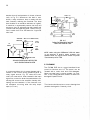
crown
INSTRUCTION MANUAL
SERIAL
NO.
ISSUED
TO
-----
------
D-60
DUAL-CHANNEL
POWER AMPLIFIER
CROWN INTERNATIONAL INC. BOX 1 000 ELKHART, INDIANA 4651 4
Section 1
DESCRIPTION
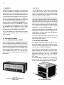
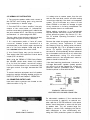
1.1 GENERAL
FIG. 1 - 1
INTEGRATED CIRCUIT STEREO
D-60 AMPLIFIER
The D-60 is a dual-channel medium power ampli
fier for u ltra-low distortion amplification from
A total of 24 discrete transistors, l linear IC (dual
op amp), 14 diodes and 1 bridge rectifier are uti
lized in a CROWN-pioneered Class AB+B output
circuit The effective number of semiconductors
is 40 transistors and 24 d iodes
5Hz to 20KHz with operation into loads of 4 ohms
and higher. The unit features extremely low har
monic and intermodulation distortion, very low
noise, highest "damping factor," and qua lity parts
and workmanship. The unit may be wired to pro
duce a balanced 25 volt monaural output. The am
plifier is fully protected against mismatched and
shorted loads by a resetting V-1 (volt-ampere)
limiter having no obnoxious muting or program
delays.
The input voltage-ampl ifiers, (IC), are powered by
two voltage-regulated supplies. This results in
complete channel-to-channel isolation and inde
pendence from line voltage variations.
Two level controls are mounted on the front panel
to allow balancing and optimizing of system levels.
The power supply features large computer-grade
fi lter capacitors.
1
2
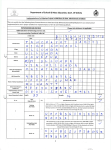
1.2 SPECIFICATIONS
1.2.1 STEREO SPECIFICATIONS
35
Output Power
watts per channel m1mmum RMS (both channels or•er
ating) into an 8 ohm load over a bandwidth of 20Hz-20KHz at a
rated RMS sum total harmonic distortion of 0.05% of the fun·
damental output voltage.
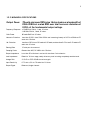
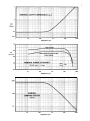
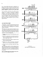
Frequency Response
;:0. 1dB 20Hz-20KHz at 1 watt into 8 ohms;
.±.1.2dB 5Hz-100KHz at 1 watt into 8 ohms.
1 KHz Power
40 watts RMS into 8 ohms, per channel, both channels operating, 0 . 1 % total harmonic
distortion.
Harmonic Distortion
Less than 0.001% from 20Hz-400Hz, and increasing linearly to 0.05% at 20KHz at 35
watts RMS per channel into 8 ohms.
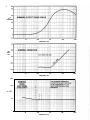
I.M. Distortion
(60Hz-7KHz 4:1)
Less than 0.05% from 0.01 watts to 0.25 watts, and less than 0.01% from 0.25 watts to
35 watts into 8 ohms per channel.
Slewing Rate
6 volts per microsecond (slewing rate is the maximum value ofthe first derivative ofthe
output signal, or the maximum slope of the output signal).
Damping Factor
Greater than 400, DC-400Hz into 8 ohms.
Output I mpedance
less than 15 m i l l iohms in series with less than 3 microhenries.
Load I mpedance
Rated for 8 ohm usage; safely drives any load including completely reactive loads.
Voltage Gain
20.6;:2% or 26.3;:0.2dB at maximum gain.
I nput Sensitivity
0.75 volts ±2% for 28 watts into 8 ohms.
Output Signal
Unbalanced, dual channel.
TABLE OF CONTENTS
Section 1
1.1
1.2
1 .3
1.4
1.4.1
1.4.2
1.4.3
Section 2
2.1
2.2
2.3
2.4
2 .4 . 1
2.5
2.6
Section 3
3.1
3.2
3.3
3.4
3.5
Section 4
4.1
4.2
4.3
Section 5
PAGE
DESCRIPTION
General
1
Specifications . . ....... ...................................................................................... 2,3,4,5,6,7,8,9
Warranty ........................................................................................................................ ... 10
Accessories ............ ............................................................... ........................................... 10
"R" Series Walnut Enclosures ........................................................................................ 10
VFX-2A ....................... ....... ................................................................................................ 10
UMX-300 Transformer .................................................................................................... 10
. . . . ............ . . . . . . . . . . . . . . . . . . . . ................ . . . . . . . .......... . . . . ..... . . . ............................. ........... . . . . . .
INSTALLATION
U n packing ....... ................... ..............................................................................................
Mounting ......................................................................... ............................ . . . ..................
Normal Hi-Fi Installation ........ ...... ........ ....................................................... ....................
Connecting Output Lines ............................................................................ ....................
Mono Operation .............................................................. .................................................
Connecting Input Lines .......... .........................................................................................
Connecting Power ......................................................................................................... ...
OPERATING INSTRUCTIONS
Controls and Adjustments ..... ...... .......... .........................................................................
The Protection Mechanisms . . ......................... .............................................. ..................
Operating Precautions ........................ .............................................................................
Load Protection Methods ....... .................................................... ....... .......... .. . .................
Cleaning ................................ ............................................................................................
11
11
13
13
14
15
16
17
17
19
19
20
CIRCUITRY
Principles of Operation ............................................... .................................................... 2 1
Test Procedures .............................................. .............................. ................................... 2 1
Service ........ .................. .................................................................................................... 22
APPLICATION NOTES
Note #1 V-1 Limits of a Load ......................................................................................... 23
Note #2 Speaker Protection .... ....................................................................................... 25
LIST OF ILLUSTRATIONS
TITLE
1·1
1·2
1·3
2· 1
2·2
2·3
2·4
2·5
2·6
2·7
2·8
2·9
3·1
3·2
3·3
3·4
3·5
D-60 Pictoria l .......................................... ........................................................................... 1
0·60 and VFX·2A in Optional S· R Enclosure ................................................................ 10
U MX-300 Transformer ............................................................................ ... ..................... 10
End-Cap/Bracket Mounting ........................................................................................... 1 1
Mounting Dimensions ......... ............................................................................................ 1 1
Normal Hi·Fi I nstallation ................................................................................................. 12
Rear View of Chassis .................................................... ................................................... 13
Schematic for Full Range Electrostatic Speaker Connection ...................................... 13
Source Resistance and Damping Factor vs. Length and Size of Output Leads ........ 14
D-60 Mono Hook-up ........................ ................................................................................ 15
Graph for Selection of I n put Capacitor ......................................................................... 15
Low-Pass Filters for Severe RF at I n puts ....................................................................... 15
Operating Controls ........................................................................................................... 17
Graph of VI Operating Range of D-60 Output ............................................................... 18
Fuse Selector Nomograph for Loudspeaker Protection ... ............................................ 19
Relay-Controlled Protector with Overload Indicator ..................................................... 20
Turn-on· Transient M uter for Load Protection ............................................................... 20
Schematic
3
1.2.2 MONAURAl SPECIFICATIONS
Output Power
70 watts minimum RMS into a 16 ohm load over a bandwidth of
20Hz-20KHz at a rated RMS sum total harmonic distortion of
0.05% of the fundamental output voltage.
Frequency Response
.±0.2dB 20Hz-20KHz, 1 watt, 16 ohms .
.±1dB 6Hz-50KHz, 1 watt, 16 ohms.
1KHz Power
80 watts RMS into 1 6 ohms.
Harmonic Distortion
Less than 0.001% from 20Hz-400Hz and increasing linearly to 0.05% at 20KHz at 70
watts into 1 6 ohms.
I.M. Distortion
Less than 0.05% from 0.01 watts to 0.25 watts, and less than 0.01% from 0.25 watts to 70
watts into 1 6 ohms.
Slewing Rate
1 2 volts per microsecond.
Damping Factor
Greater than 400, DC-400Hz into 1 6 ohms.
Output I m pedance
Less than 30 milliohms in series with less than 6 microhenries.
Load Impedance
Rated for 16 ohm usage, safely drives any load including completely reactive loads.
Voltage Gain
4 1.2.±2% or 32.3±.0.2d8 at maximum gain.
Input Sensitivity
0.75 volts ±2% for 70 watts into 16 ohms.
Output Signal
Balanced, single channel.
4
1.2.3 GEN ERAl SPECIFICATIONS
1 06d B below rated output.
Hum and Noise
(20Hz-20KHz)
Phase Response
+10, -15° 20Hz-20KHz at 1 watt.
Input Impedance
25K ohms :<:30%.
Amplifier Output
Protection
Short, mismatch, and open circuit proof. V-l limiting is instantaneous with no annoy
ing thumps, cutout, etc.
Overall Protection
AC line fused. Controlled slewing rate voltage amplifiers protect overall amplifier
against RF burnouts. Input overload protection is furnished by internal resistance at
inputs of amp.
DC Output Offset
(Shorted Input)
10 mil livolts or less.
Turn-on
Instantaneous, with minimum thumps and no program delay.
Circuit
Wideband multiple feedback loop design utilizing one linear IC (dual op-amp). Total
equivalent of 40 transistors, 1 8 signal diodes, 2 zeners, and 4 rectifier diodes.
Power Supply
Special design low profile transformer. Computer grade filter capacitors. Two
regulated supplies for complete isolation and stability.
Power Requirements
Requires 50Hz-400Hz AC on 100, 120, 200, 220, or 240 volts± 10% operation
Draws 15 watts or less on idle, 120 watts at 70 watts total output.
Heat Sinking
The entire amplifier is used as a heat sink. Front panel extrusion acts as a heat sink
along with the chassis covers.
Chassis
Aluminum chassis construction for maximum heat conduction and minimum
weight.
Controls
Two input level controls on front panel with power switch and pilot light. A mono
stereo switch is located next to the input jacks on the rear panel.
Connectors
Input - 1/. inch phone jack.
Output - Color-coded binding posts with stereo '!. inch earphone jack on front
panel.
AC Line - Three-wire (grounded) male connector on 5 foot minimum cable.
Dimensions
17 inches long, 8% inches deep, and 1% inches high (8 inches deep from mounting
surface). 1 9 inch standard rack mou nting hardware included.
Weight
10 pounds net weight
Finish
Satinized aluminum front panel with gray suede Lexan insert.
jf i
+1
'
i
ii
0
f
i
-1
-2
-3
i ':
, I
'
I
I
!
l
I ill
<CTO DC
!
i
I: t
u
'!
'
_.I
•
.
,·r
I '
,
,
I
,
:
l
��
16ohms
8ohms
'
••
, . : !r
!
lK
'
I
!
:
I
I
100
i',
Dl:�l
;y
I
'1:
• I
•
;
I
10
'
':
' 'i
i
i
I
iMINAl FRl:1
I
I
:
I' I I i
;
I
i
N
I
I
I
5
4ohms
!I
II
lOK
lOOK
FREQUENCY (Hz)
ii
+5
!
0
r
-5
I
+5
DB
0
L
I
!
+5
i
.
!
I;.
!
f
!
I
!.
i
I :
i!
.!
:
!
10
I
t
•
I
i
i
I I;
r
i
I
I
•
I
i
I
•
I'
1
!
· .
i
100
1K
I
I
!
I
i
.
r
.
I
i
'
I� f
I
I
:!
r.f I
I
•
r''
.
I
I
•
I
:
!
!.
!
I!
11
r
lOK
I
I
40w
i
!
q
!
!
I
! /1
I
, t
I
I
I
r·I
'
l1r
.
I
i
!
!
!
:
;
i
I
I
I
I
I
i
i
' ! ':
I
r
i
i!! ·:
'!'��� lPer 'i"�'i','
!
. :; I i
I
•
ol�cLe�H; !
U
_r 'Tr
iv
ii
·n
I
d !
I
I
-5
.
'
. I
.
'F
!
:
I '
•
"_,._.,,
!
!
:I ! :
! !
.
i !
•
•
I'IU�II'fA'""�'!J,Ytt<
:
0
!
!
i
·•
I
-5
!
30w
l ill
I
i li
T I
I
l
j
20w
.' l
lOOK
FREQUENCY (Hz)
+20
+10
0
PHASE
SHIFT
-10
(degrees)
-20
-30
-40
10
100
lK
FREQUENCY (Hz)
lOK
lOOK
6
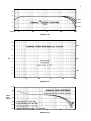
.1
NOMINAL HARMONIC DISTORTION
.01
DISCLOSURE
PROHIBITED
effective Nov. 4. 1974
.001
lK
100
10
lOK
lOOK
FREQUENCY (Hz)
.1
.08
.06
NOMINAL INTERMODULATION DISTORTION
.04
.02
I.M.
0
%
.06
TEST
INSTRUMENT
RESIDUAl
.04
0.001%
.
02
(typ)
DISCLOSURE
PROHIBITED
0
effective Nov. 4. 1974
.06
.04
.02
.01
.1
1
POWER OUTPUT (Watts)
10
100
7
1
.1
.01
.004
1
10
100
lK
lOK
lOOK
FREQUENCY (Hz)
P.E.
(per cent)
501-�:-4-+++4+��-+-+-++4�-+-+-+++���--+-��-+4��··��.+
10
lK
100
lOK
lOOK
FREQUENCY (Hz)
I!
ll
.::l±
. H
P
�·
I
I
I
I
•
i
�---=:'c::.L.-::
'
-·--
'\.
....
�- -
10
lK
100
FREQUENCY (Hz)
lOK
-�'(
! II
i
i:
lOOK
8
60
LZo
.
(DEGREES)
i
40
100
10
lK
lOK
lK
lOK
lOOK
FREQUENCY (Hz)
DB
below
30w
10
100
lOOK
FREQUENCY (Hz)
400
i
N
�-
i
1
I
·If I
I
100
•
nV/YHZ
i
i
10 cc
--
I
I
.....
.
. .. .
....
-
�···
. .. .
•
1
10
100
FREQUENCY (Hz)
lK
lOK
I
I
lOOK
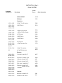
PARTS liST, D-60 Page 1
(Starts Sill 17526)
Schematic
Designation
Description
Crown
Part#
Other Information
MAIN MODULE
41119
PC Board
7925
Capacitors
ClQl, C201
25 M F 1 5V N P Vertical
3 1 86
C102, C202
C107, C207
Cll5, C2l5
200 PF M ica
34 1 1
C 1 03, C203
100 M F 16V Vertical
3729
C 1 06, C206
.0015 M F 200V Filmatic
3089
Cl08, C208
27 P F Mica
2342
C109, C209
100 PF M ica
34 10
CllO, C210
Clll, C2 1 1
120 PF Mica
3290
Cll2, C212
47 PF Mica
3409
Cll3, C213
Cll9, C219
C4, C7
. 0 1 M F Ceramic Disc
1751
Cll6, C216
1 0 M F 50V Vertical
3728
C5
4.7 M F 63V Vertical
4253
Resistors
R 1 02, R202
R 1 08, R208
1K ohm 114 watt 5% CF
2627
Rl03, R203
5 1 0 ohm y, watt 1 o/o Film
3304
R 104, R204
10K ohm '14 watt 5% CF
2631
R 106, R206
22K ohm 114 watt 5% CF
3302
Rl07, R207
3.9K ohm 114 watt 5% CF
2630
Rl09, R209
56K ohm '14 watt 5% CF
2882
RllO, R210
Rll8, R218
Rl24, R224
lOK ohm Y, watt 1 o/o Film
2343
R 1 1 1 , R21 1
Selected
Rll2, R212
820 ohm 114 watt 5% CF
3301
Rll4, R214
56 ohm '14 watt 5% CF
35 1 1
PARTS liST, D-60 Page 2
Schematic
Designation
Description
Crown
Part#
Rll5, R215
Rll6, R216
4.7K ohm Y, watt 5% CF
1640
Rll7, R217
18K ohm ';.\ watt 5% CF
2633
Rll9, R2 1 9
Rl25, R225
180 o h m 1;.\ watt 5% C F
2873
Rl20, R220
Rl27, R227
5.6 ohm y, watt 5%
3299
Rl21, R221
Rl22, R222
120 ohm y, watt 5% Film
3837
Rl23, R223
100 ohms Y, watt 5% CF
1007
Rl26, R226
2.2K ohm Y, watt 5% Film
3 1 45
R 1 32, R232
750 ohm 1;.\ watt 5%
3803
*Rl35, R235
3.3K ohm ';.\ watt 10%
2629
When IC u749 is used, must be
connected from pins 1 to 7 and
7 to 13 on IC
*R1 35, R235
lOK ohm 1;.\ watt 1 00!6
2631
When IC u739 is used and in·
stability occurs, resistor must be
connected from pins 1 to 7 and
7 to 13 on I C
1.5K ohm 1 watt 10%
3497
R5
Rl3
Other Information
Transistors
Ql02, Q202
PN4250A
3786
Ql04,
Ql05,
Ql06,
Q 1 1 4,
2N 3859A selected
2961
Ql07, Q207,
Qll5, Q215
2N4125 selected
3625
Ql08, Q208
M PSA06
3528
Q 109, Q209
M PSA56
3954
QllO, Q210
Q 1 12, Q212
2N6175
3501
Q204
Q205
Q206
Q214
Diodes
DlOl, D20l
D 1 02, D202
Dl06, D206
1 N4148
3181
D 103, D203
1 N 270
3447
Dl04, D204
Dl05, D205
1 N 4003
2851
D7, D8
1 N 96 18, 10V zener
3549
Qll5, Q215 started SN 1 7526
PARTS liST, D-60 Page 3
Schematic
Designation
Description
Crown
Part II
Other Information
Integrated Circuits
IC-1A, B
uA739 or
uA749
3231
3643
May be substituted for uA739 with
proper load resistor
Coil
Ll01, L201
.5MHY axial lead
3510
Miscellaneous
14 pin DIL IC socket
3450
Dual T0-92 cooler
3493
Used on Q 1 08, Q208; Q 1 14, Q214
Transistor lead PC receptacle
351 9
Used to mount Rlll, R2 1 1
4-40 x % RHS screw
1844
Used to mount QllO, Q210, Ql12, Q2 12
114 internal star washer
1824
Used to mount QllO, Q2l0, Q 1 12, Q212
T0-5 mica washer
3530
Used to mountQl10, Q210, Q 1 12, Q212
4-40 hex nut
1938
Used to mountQ1 10, Q210, Q 1 1 2, Q212
BACK CHASSIS ASSY.
D-60 rear panel
9599-S
Dual binding post
2823
Heyco strain relief
2803
3 #18 male power cord
3474
HTA fuseholder
3256
2A 3AG fuse
2 1 63
External fuse for operation below 200V
lA 3AG fuse
3065
Externa I fuse for operation 200V and a bove
1 1 2A, 2 -cond. Hi-D jax
3423
Fiber washer
1646
Mounts jack
Fiber shoulder washer
1306
Mounts jack
R36
10K y, watt 1 % Film
2343
Cl22, C222
.l MF 200V Filmatic
2938
Mounted on output term inals
R129, R229
2.7 ohm 1 watt 10%
100 1
Mounted on terminal strip
SW2
DPDT slide switch
4 1 10
Mono-Stereo switch . Earlier
units used CPN 2668.
Brass eyelets
3529
Fastens SW2
OUTPUT
F2
INPUT
Fastens power cord
PARTS LIST, D-60 Page 4
Schematic
Designation
Description
Crown
Part#
Other Information
CAPACITOR BRACKET ASSY.
C23, C24
DM1
R34
10,000 M F 40V
4250
Solder lug
2934
10-32 x Y2 T H P screw
2049
#6 flat washer
2101
# 1 0 i nternal star washer
2279
'A" fiber shoulder washer
1648
VH148, 6A bridge
3062
#6 solder lug
3 1 63
6-32 hex nut
1889
6-32 x % B H P screw
2134
1 o h m y, watt 5% CF
3612
Mounted on common term inal for
C23, C24 to lug at OM l.
D-60 bracket
9591-S
Fastens both sides of main PC board
4-40 x 'A" SSET screw
4163
#4 internal star washer
1824
4-40 hex nut
1938
8-32 x '14 THP screw
2271
#8 internal star washer
1951
8-32 captive nut
2018
Terminals for C23, C24
FRONT PANEL ASSEMBlY
D-60 front panel
4083
D-60 front panel overlay
4084
Nll2B 3-cond. Hi-D jax
3507
:Ys'' internal star washer
2188
One on jack, one on SW1
%" black washer
3628
Mounts jack
:Ys" black knurled nut
3495
Mounts jack
114" i nternal star washer
2365
Mounts RlOl, R201
Solder lug
3515
Mounts over R101
Terminal strip
3503
6-32 x :Ys B H P screw
2134
Mounts term inal strip
6-32 hex nut
1889
Mounts terminal strip
\6" rubber transformer mount
3556
Mounts on back of Tl
Nylon transformer pin
3557
Mounts Tl to front panel
Speed nut
3558
Mounts Tl to front panel
PARTS LIST, D-60 Page 5
Schematic
Designation
Description
Crown
Part#
Other Information
3" foam tape
1 1 52
Mounts T l to front panel
6-32 captive nut
2019
Mount on bottom back edge of FP
channel
Anodized T0-3 insulator
4039
Mounts outputs
T0-3 insulator
4071
Mounts outputs
6-32 x y, B H P screw
2176
Mounts outputs
#6 internal star washer
1823
Mounts outputs
#6 solder lug
3 163
Mounts outputs
6-32 hex nut
1889
Mounts outputs
Feed-through terminals
3502
C6
. 0 1 M F ceramic disc
1751
C21
5MF 70V
1678
11
Neon lamp, NE2H
2500
SW l
D-60 power rotary switch
3492
R3l
27K ohm Y, watt 5 % C F
1056
Mounts on terminal strip
R33
2.7 ohm y, watt 5% C F
2857
Mounts from gnd lug at input pot to
main board
RlOl, R201
25K ohm audio taper pot
3494
Input level control with nut
R l 28, R228
R 1 30, R230
. 1 ohm 5 watt 10% Wire
3291
Mount on solder lugs attached to
outputs
Q l l 1 , Q211
Q l l3, Q213
2N3055 selected, Motorola
/41 52
Tl
D-60 transformer, 10403-P2
4246
Starts SN 14484
Nylon shoulder washer
4251
Mounts transformer
8-32 x Ys R H P screw
4252
Mounts transformer
Fuseblock
3776
Double-sided foam tape
1 1 52
U sed to mount fuseblock
2.5A AGC fuse
3775
Interna I fuse
Fuse Caution label
4402
Control knob, A-1
4076
For input pots R 1 0 1 , R201
Control knob, A
4075
For power switch SW 1
D-60 serial number label
4193
*2A 120 VAC* label
3891
1%" end bars
4085
6-32 x % SCP screw
1858
Mounts end bars
D-60 bottom cover
4 1 166
W ith 2, 8-32 captive nuts
D-60 bottom cover
9590-S
Without the captive nuts
8-32 captive nuts
2018
Insta l l o n bottom cover
. 0 1 M F Ceramic disc
1751
F1
C123, C223
C125
M ounts on terminal strip
Output transistors on bottom of
FP channel
PARTS LIST, D-60 Page 6
Schematic
Designation
Ll02, L202
Description
Crown
Part#
Other Information
8-32 x 'I< FHP screw
2136
Mounts bottom cover
8-32 x Ys FHP screw
2274
Mounts bottom cover
6-32 x 'I< FHP screw
2436
Mounts bottom cover
Self-stick rubber feet
3342
I nstalled on bottom cover
D-60 top cover
9614
6-32 x % BHP screw
2134
Holds front of top cover
#8-18 x Ys #6 SMT screw
3958
Holds back of top cover
OUTPUT I NDUCTOR ASSV.
4 1 145
Output torroid core
2850
15%" #18 brown wire
3585
8-32 x 1 Vs TH P screw
2277
Nylon spacer
2762
Insulates coil from screw
Nylon washer
3609
One each side of coil
#8 i nternal star washer
1951
Mounts coil
8-32 hex nut
1986
One each side of coil
# 10 solder lug
33 12
Mounted under coil
2ALUE #10 term inal strip
3504
Mounted on top of coil
ACCESSORIES
RMB-2 Kit
4 1 626
4 x 4 polybag
3046
7/64 Al len wrench
3454
13;4" rack mount
4086
10-32 panel thumbscrew
washer assy.
20032
Hi Fi Adapter Kit
40377
Pin-phone cables
3339
Dual banana plugs
2981
Model 748 wire nuts
3069
Poly bag
3073
3 AG Fuseholder
with 1 . 5A fuse
4245
9
16
14
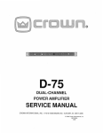
NOMINAL LIMITS
OF
12
V-1 OUTPUT
10
8
6
4
2
DISCLOSURE
PROHIBITED
0
effective Nov. 4. 1974
·2
-4
·6
-8
·10
-12
.
-14
._____________�----------------------------------------·16
-60
·50
-40
-30
·10
0
10
20
30
40
50
60
1our
10
1 . 3 WARRANTY
1.4.2 VFX-2A
CROWN guarantees this equipment to perform as
specified. CROWN also warrants the components
and workmanship of this equipment to be free from
defects for a period of 3 years from date of purchase.
The CROWN VFX-2A is a dual-channel variable elec
tronic filter-crossover. When used with a power
a mplifier it can greatly add to the total system capa
bil ity. In combination with the D-60, theVFX-2Aadds
several convenient useful function s .
This warranty does not extend to fuses, and/or com·
pcnent or equipment damage due to negligence,
misuse, shipping damage or accident; or if the serial
number has been defaced, altered or removed.
A copy of the FULL THREE-YEAR WARRANTY is in
cluded with this manual. The WARRANTY is subject
to the conditions contained therein. Upon receipt of
the registration form, CROWN will issue a WAR·
RANTY TITLE. This title applies to the original end·
purchaser as well as subsequent purchasers.
You, the purchaser(s), are respcnsible for accurate,
complete records (sales slips, invoices, etc.) for
FULL coverage!
1.4 ACCESSORY EQUIPMENT
1.4.1 "R" SERIES WALNUT ENCLOSURES
Rich oiled-walnut veneers, highlighted with flatback
trim, accent the D-60 when installed on a shelf or ta
ble in an "R" series enclosure. The design of these
enclosures permits vertica l stacking of several com
pcnents. Several cabinet sizes are available which
accommodate multiple components in one enclo
sure. Available sizes are 5-R, 7-R, 10-R, and 14-R.
Custom sizes are available through our factory Parts
Department.
The connections are made with t h e VFX-2A quickly
and easily. lfa balanced line is to be used with the un
balanced input of the D-60 the VFX-2A can serve as
the interface. While maintaining these functions the
output can be shaped by selecting variable high
pass, lo-pass, or band-pass filters. As a filter, the VFX2A can be used as a crossover or ahead of several
amplifiers in a bi- or tri-arnped system.
Overal l noise and distortion are extremely low, with
I M distortion less than .0 1% at rated output (2.5V in
to 600 ohms), and noise more than 100 dB below
rated output with 0 dB gain.
For further information please request the VFX-2A
specification sheet or for a nominal fee, purchase a
VFX-2A instruction manual.
1.4.3 UMX-300 TRANSFORMER
The CROWN UMX-300 transformer offers a maxi
mum 300 watts of power with I M distortion of less
than .015%. Frequency response for the unit is rated
+0, - 1 dB, 20Hz to 20KHz at 300 watts.
Connections are made through a five-screw input
output terminal strip mounted on the front. Three
holes in the flanges on each side of the casing allow
convenient mounting of the unit. The U MX-300
weighs 23 lbs. and measures 6" high x 4.75" wide x
5.25" deep.
The auto-transformer configuration can convert any
input of 25, 35, 50 or 70 volts to an output of 25, 35,
50, or 70 volts at any power level up to 300 watts.
FIG. 1 -2
D-60 and VFX-2A IN OPTIONAL 5-R
FIG. 1 -3
ENCLOSURE
UMX- 3 0 0 TRANSFORMER
Section 2
INSTAllATION
Sufficient ventilation must be provided for the unit.
This means that air must be allowed to circulate over
the chassis to prevent overheating. Applications other than "Hi-Fi" - requiring long, sustained sig
nals at high power-levels may require the use of a
cooling fan. When rack mounting, it is a good prac
tice to allow a l%" space above and beiow the unit.
(See figure 2-2 for mounting dimensions.)
2.1 U N PACKING
As soon as the amplifier shipment is received,
please inspect for any damage incurred in transit
Since the unit was carefully inspected and tested
at the factory, it left the factory unmarred. If dam
age is found, notify the transportation company
immediately. Only the consignee may institute a
claim with the carrier for damage during ship·
ment However, CROWN will cooperate fully in
such an event. Be sure to save the carton as evi
dence of damage for the shipper's inspection.
I� I
Even if the unit arrived in perfect condition - as
most do - it is advantageous to save the packing
materials. They will prove valuable in preventing
damage should there ever be occasion to transport
or ship the unit Note the carton and internal pack
each is designed for protection during transit Do
not ship the unit without this factory pack!
1i o
1
0
'I(
,
o
o
'<;
+
®
@
"
®
0
iiiHiiiiiH!IiiH I
0
I
•
•
'\
Ia
a
I
;,
BRACKET
l
0
•
·"
I
I
I
I
H
0
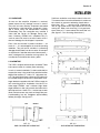
FIG. 2-1
FIG. 2-2
END-CAP/BRACKET MOUNTING
D-60 MOUNTING DIMENSIONS
11
II :�
__.I
___
""
Angle brackets supplied with the D-60 are used for
rack mounting and for installation into the 5-R or
other larger CROWN "rack" cabinets. Align these
angle brackets on the unit to match the holes which
held the end bars. Use 6/32 x Y, socket cap screws
(Note: Socket screws may look as though they a re
crossthreading but will straighten approximately
halfway through). See figure 2-1.
I
I
o
,., ,,_
l_
In such a "custom installation," install a solid shelf, to
support the amp. It should be flush with the bottom
edge of the required 17" wide x 1 %"high panel-cut
out The shelf should have a hole cut in it to allow air
to circulate freely to the louvers in the bottom cover.
END
o
,;.;.
The D-60 is shipped with end-caps installed. These
end-caps are used for custom panel mounting.
0
"
....--c���-
r
2.2 MOUNTING
0
oo
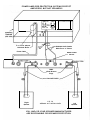
POWER AMPLIFIER PROTECTION SYSTEMS PROTECT
AMPLIFIERS, BUT NOT SPEAKERS!
TI'UT
MAIN
2
t
2
�
•..,
r--- RIGHT
®ro®
POWfR AMP
3 to 2 wire adapter
Switched Outlet
Tie
TAP!
1
@ ®
�
'Ill ro IS>
RECORDER
INPIIT
_...-:;- Shielded Audio Cables
RCA Pin-to-W' Phone
MONO-STEREO
SWITCH
Power Cable
MDP
(Dual Banana)
Plugs
Note! IN-LINE FUSES
FIG. 2-3
Right
NORMAL HI-FI INSTALLATION
Speaker
YOU, AND/OR YOUR SPEAKER MANUFACTURER
ARE RESPONSIBlE FOR SPEAKER PROTECTION
Left
Speaker
13
2.3 NORMAl HI-FI INSTAllATION
1. Two-conductor speaker cables must connect to
the OUTPUT dual binding posts using terminal
lugs, tinned ends, or "banana" plugs.
2. Since the 0-60 is a "basic amplifier," the main
outputs of the control-center or "preamplifier"
must be connected via shielded audio-cables to the
two jacks marked INPUT. Use RCA-pin at preamp
and standard 14 in. phone-plug at the 0-60.
The two cables should be tied parallel a long their
entire length using the accessory cable ties.
3. U/L requirements prefer a 3-wire AC power
connector; however, proper connections to a
switched outlet on the control center requires the
use of a 3-to-2 wire adapter. NOW, plug the AC
into a switched outlet on the control center.
4. Your Control Center may now be turned on.
Then advance the D-60 Input-Gain Controls about
Y,-open (150° clockwise).
When using the CROWN IC-1 50A Control-Center,
the VOLUME should attain almost full rotation
(2 to 4 o'clock) for loudest "concert-hall" volume
If at 3 o'clock the volume is low, increase the D-60
input gain controls; if too high, decrease the D-60
gains
To assure maximum enjoyment and full speaker
protection, read the following detailed sections on
OUTPUTS, INPUTS and C hapter 3 - OPERATION.
It is always wise to remove power from the unit
and turn the input level control s off while making
connections, especially if the load is a loudspeaker
system. This will eliminate any chance of loud
blasts. CROWN is not liable for damage incurred
at any transducer to its being overpowered! The
use of speaker fuses is recommended.
Before making connections, it is recommended
that the operator familiarize himself with the am
plifiers protective system. See Section 3.2. Sec
tion 3.3 entitled "Operating Precautions" should
also be read.
Because the output wire gauge and length raises
the r e s u l ta n t source i m pedance or lowers
the Damping Factor by adding series resistance,
the nomograph (Fig. 2-6) is provided for wire se
lection. For dynamic moving-coil loudspeakers
the value RL should preferably be that measured
by an ohmmeter across the voice coil, rather than
the manufacturer's rating. For e l e c t r o s tatic
speakers and such, the manufacturer's rated im·
pedance should be used for RL.
If the load (matching transformer, inductance, or
full-range electrostatic speaker system) appears
as a short-circuit at low frequencies, a large non
polarized capacitor (paralleled with a resistor)
should be placed in series with the load.
4n,20W
fvlt --..
IMctro.tatlc
( HcwlaQ no
Wodr.lne
capacitor}
2.4 CONNECTING OUTPUT liNES
Input and output connectors are located on the
chassis as shown in Fig. 2-4.
FIG 2-5
SCHEMATIC FOR FULL RANGE
ELECTROSTATIC SPEAKER CONNECTION
FIG. 2-4
REAR VIEW OF CHASSIS
For electrostatic speakers (if the manufacturer
has not provided a capacitor) an external non
polar capacitor of 590-708 mfd and 4 ohm power
resistor should be placed in series with the plus
(+) speaker lead. This will prevent large low
frequency currents from damaging the electro
static transformer or from unnecessarily acti
vating the D-60's protective system. An effective
14
....
40
R,
LOAD
R,
Rs
30
06
.
SOURCE
(ohmsl
2
•
100
••
••
"
20
" ,<'
.� �
.... .{\>
•
•
.. ..
!0
••
,.
.�· ....�
... ,,
.,o
�
""..-.;.
CADLE
..�•If•
,.-#
...
5
•
(AWG)
-#21
100
-#26
50
#24
-#22
•••
10
-#1&
-$16
s
5
WIRE
500
20
2
-#14
-·12
-#10
.,.,
, ,.�
•
2·COND.
10
•
COPPER
1000
(f-tl
20
10
ANNEALED
tn/1000 ft.)
.1
FACTOR
(ohmJ)
lis
RESISTANCE
DAMPING
RESISTANCE
8000
2000
2
•
-#8
-#6
$000
••
•
6
-#4
-#2
7
- #0
-#00
10
.I
6
-#0000
•••
s
20
.l
40
.01
FIG. 2-6
SOURCE RESISTANCE and DAMPING FACTOR VS. LENGTH and SIZE of OUTPUT LEADS
test to determine if such parts are needed is to
measure the DC resistance between the output
terminals with an ohmmeter. If the resistance is
less than 3 ohms, the parts should be added as
shown schematically in Fig. 2·5.
When selecting connectors for the load (speaker)
end of the output lines, the following general pre
cautions apply (with a l l power connectors):
l.
2.
3.
4.
5.
A male plug, carrying signal, must not be on
the far end of the line where it can be ex·
posed, giving rise to both shock and short
circuit hazards.
Connectors which might accidentally cause
the two channels to be tied together during
making and breaking of connection should not
be used.
C o n n e c t o r s which can be p lugged into AC
power receptacles should never be used.
Connectors having low-current carrying ca
pacity are "verboten."
Connectors having any tendency to short, or
having shorted leads, are unadvisable.
2.4.1 MONO OPERATION
A mono-stereo switch on the rear panel adjacent to
the input jacks, al lows the D-60 to be operated nor·
mally (:;tereo) or in mono, with no internal modifica
tion. (See figure 2-7.) When in the mono position, the
input circuitry of the D-60 is changed so that the two
ampl ifiers are "added" for mono output. (See mono
specifications, page 3).
Care must be taken in the external hook-up to assure
proper operation. Proceed as follows:
1. The input line should be plugged into the chan
nel 1 input jack. The level is adjusted with the
Channel 1 input level control.
NOTE: The Channel 2 input jack and level control
are not defeated in the Mono mode. However, the
C hannel 2 input should not be used in this mode.
If a Channel 2 input is added to the Channel 1
input, distortion may result. If Channel 2 input is
used alone, very low power output w i l l result. For
best results unplug the input to Channel 2 when
operating Mono.
15
2. Connect output lines as per the following draw
ing, Figure 2-7. The output from the D-60 in Mono
is BAlANCED and is isolated from the chassis,
and from the input grounds to the D-60.
CAUTION: Be certain that a l l equipment (meters,
switches, etc.) connected to the Mono output
lines is balanced. Both sides of the line must be
totally isolated from the input grounds, to the D60. if this is not observed, severe oscillation may
result.
For loudspeaker-driving applications, the input
should be free of large sub-audio or undesired low
frequencies, as they cause overheating and over
loading of the loudspeaker. To remove such low
frequencies, a series capacitor may be placed in
the input signal line. (The graph of figure 2-8 in
dicates the effect of the size of the capacitor on
the frequency response.) Only a low-leakage paper,
mylar, or tantalum capacitor should be used for
this purpose.
...
•
_,
-··
_.,
'�
'/�
....�-.
....
,.
v
�
.....
'"'
;w·
.....
10CMI
fRlQUINCY
lOKH.11
FIG. 2-8
GRAPH for SELECTION of INPUT CAPACITOR
If large amounts of ultrasonic o r RF frequencies
are found on the input, such as bias from tape re
corders, etc., a low-pass filter should be placed
on the input. While practically-obtainable RF input
levels will not damage the amplifier, they may
cause burn-out of t w e e t e r s or other s e n s i t i v e
loads, activate the ampl ifier's protective systems,
or cause general overload in the control led-slew
ing-rate stage of the amp (which is employed to
provide RF overload protection). The following
filters are recommended for such appl ications.
I
i
FIG. 2-7
D-60 MONO HOOK-UP
�·
.oo;- "'"'.o�A.,.
R.....,
"'T
l
2.5 CONNECTING INPUT liNES
Connecting the inputs will require observance of
three basic precautions: Undesirable signals to the
inputs, "ground loops," and feed back from out
put(s) to input(s).
In high-fidelity audio a p p l i cat i o n s any good
vacuum-tube or solid-state control center will
operate successfully into the 25K ohm inputs of
the D-60. Occasionally a high-impedance output of
poorly-designed preamps will be encountered, and/
or a larger output coupling capacitor may be re
quired (to prevent excessive low-frequency rolloff).
_
(.
NOTI: A to-% R5c..nb<o
1.,....,..,.. .., 6004'1 by Gn
-'-" ..•1•--
I
I
4Kib
I
A
!
'I
I
..
•
'•
c
I
_..A'lR__ _ ••
•-�"'"'.o�"'
�·
., , I IGI\ID
I
:-;;:: ..:
'\\.
"\"
I
GNC
8.
I
"
IOKHo
tOOKHa
fUQUINCY
FIG. 2-9
LOW-PASS FILTERS
FOR SEVERE RF AT INPUTS
A second precaution is "ground loops" - elec
tronic jargon for undesirable circulating currents
flowing in a grounding system. A common form of
loop (possibly resulting in hum in the output) is a
16
pair o f input cables whose area i s subjected to a
magnetic hum field. In practice, both cables should
lie together along their length, and away from the
power transformer. Tying the input and output
grounds together may also form a ground loop.
A third precaution (with input and output grounds
together, as in testing or metering) is feedback
oscillation, from load current flowing in the loop.
In industrial use, even the AC power line may pro
vide this feedback path. Proper grounding, and
isolation of inputs, of common-AC-Iine devices is
good practice. Refer to Section 4.2, par. 5 for test
; ng precautions.
100V
120V
200V
2.6 CONNECTING POWER
The amplifier is furnished with a three-wire AC plug
as standard equipment. Adapters are readily avail·
a ble commercially for adapting this to a two-wire
system if necessary.
The D-60 power supply may be connected for any of
five voltages. Converting from one to another can be
simply accomplished with a soldering iron and a pair
of wire cutters. Follow the table shown with the
schematic, and the drawing below.
.....
:I:
(!)
"'
0
3:
uov
uov
1) Remove the top cover of the D-60 (held on by 8
screws).
2) With the unit right side up, and the front panel to·
ward you, locate the terminal strip on the front in
the near right-hand corner.
3) Make the appropriate change in jumpers for the
desired operating voltage.
4) Replace the 2 amp line fuse with a 1 amp type
3AG fuse, for a l l connections 200V and above.
5) Change the line cord tag to read the correct
voltage.
When testing the amplifier, the line voltage m ust be
the peak equivalent to a sinusoid of the indicated line
voltage when at full load. Line regulation problems
can introduce serious errors in the measurements on
an ampl ifier.
Only a competent technician should attempt alter
ation of the line voltage con nections.
FIG. 2-1 0
LINE VOLTAGE CONNECTIONS
Section 3
OPERAliNG INSTRUCTIONS
3.1 CONTROLS AND ADJUSTMENTS
FIG. 3- T
OPERATING CONTROL S
load i s a loudspeaker, amplifier protection will be
evidenced by distortion in the speaker. The audible
effect ranges from something resembling cross
overnotch distortion to a snapping sound, depend
ing on the over-all load characteristics. Speaker
systems which are truly 4 ohms o r greater will
not initiate the protection system.
The D-60 contains all the facilities essential for a
high performance amplifier.
The input level controls are mounted on the front
panel. Each control should be adjusted for the de
sired amplifier gain or output level. When the con
trol is fully CW, the gain is 26db as determined by
precision 1 % resistors in the D-60's feedback loop.
The AC line for below 200V is fused with a 2A, 250V
type AG fuse (above 200V; lA type AG). The use of
any other type of fuse will invalidate the warranty.
3.2 THE PROTECTION MECHANISMS
The D-60 is protected against the common hazards
which plague power amplifiers, including shorted,
open, and mismatched loads; overloaded power
supplies; chain destruction pheomena; input over
load damage; and high frequency overload blowups.
All the amplifier's voltage-amplifiers circuitry is
designed to be inherently current-limited. There
by, if any of the devices should fail, (which is ex
tremely unlikely) no damage will occur to the rest
of the stages.
Protection against shorted and mismatched loads
is provided by an instant-acting limiter which in
stantaneously limits at the volt-ampere product to
the m a x i m u m safe-stress value for the outplft
transistors.
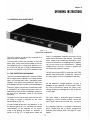
The area in which the amp will drive the load with
out being V-1 limited is depicted by the cross
hatched areas of Fig. 3-2.
The input stage is protected against overdrive
damage by a series limiting resistor should the
input signal level ever become yery excessive.
If a load initiates protection in the a mplifier, it can
be detected g e n e r a l ly by watching the transfer
characteristics of the amplifier on an oscillo
scope or by plotting the load's V-1 behavior, if
known, on to Fig. 3-2. In applications where the
The amplifier features a controlled slewing-rate
which, coupled with the V-1 limiter, protects the
amplrrier from blowups when fed large RF input
signals.
17
18
16
14
NOMINAl liMITS
OF
12
V-1 OUTPUT
10
8
6
4
2
DISCLOSURE
PROHIBITED
0
effective Nov. 4, 1 9 74
-2
-4
-6
-8
-10
-12
-14
L------' -16
-60
-50
-40
-30
-20
-10
0
"'ouT
10
20
30
40
50
60
1ouT
19
3.3 OPERATING PRECAUTIONS
10.
The following are a number of operating precau·
tions given as a n aid to understanding proper and
improper amplifier usage:
Tampering in the circuit by unqualified per
sonnel or the making of u n authorized circuit
modifications invalidates the warranty.
11.
Do not expose the output leads to areas likely
to be struck by lightning. Such an installa
tion could invalidate the a m p lifier.
1.
2.
3.
4.
5.
6.
7.
Use care in making connections, selecting
signal sources, and control ling the output
level. The loudspeaker you save may be your
own. CROWN is not liable for any damage
done to loads due to careless amplifier usage
or deliberate overpowering. For pointers on
load protection see Section 3.4.
Never parallel the two outputs by d irectly
tying them together or parallel them with any
other amp's output. Such connection does not
result in increased power output. Damage in·
curred by such operation is not covered by
the warranty.
Never drive a transformer-coupled device or
any other device which appears as a low fre.
quency short (less than 3 ohm) w i t h o u t a
series isolating capacitor. Such operations
may damage the device and/or needlessly
activate the V - 1 limiting (see Fig. 2-5).
Do not short the ground lead of an output ca
ble to the input signal ground as oscillations
may result from forming such a ground loop.
Operate and fuse the amplifier only as set
forth in section 3.2.
Operate the amplifier from AC mains of not
more than 10% a bove the selected line volt
age and only on 50, 60 or 400Hz AC. Failing
to comply with these limits will also invali
date the warranty.
Never connect the output to a power supply
output, battery, or power main. Damage in
curred by such a hookup is not covered by
the warranty.
3.4 lOAD PROTECTION METHODS
The most common of a l l protection schemes is a
fuse in s e r i e s with the l o a d. The fuse may be
single, fusing the overal l system . Or, in the case
of a multi-way speaker system , it may be multi
ple with one fuse on each speaker.
Fuses help to prevent damage due to prolonged
overload, but provide essentially no protection
against damage that may be done by large tran
sients and such. To minimize t h i s problem, high
speed instrument fuses such as Littlefuse 361000
series are most appropriate for such applications.
For a n o m o g r a p h showing fuse s i z e vs. loud
speaker ratings refer to Fig. 3-3.
•
•
400
4
300
3
200
•
150
•
7
2
Example: Z:&ft, Peak Power=30
U
Answer: FuM: 1 A
100
••
•• 1%:
•
10
12
N
..
1%:
14 � E
w ;:
16
<C i
�
Ill
1/) 0.
:::1 E
... s
W -;; .6
_.
.4
...
:!5
II.
Ill
..
20
25
1%:
lil::
2
•
••
··
··
9.
Do not e x p o s e the a m p l i f i e r to corrosive
c h e m i c a l s such as soft drinks, lye, salt
water, etc.
The amplifier is not recommended for high
power industrial usage at frequencies above
30KHz.
30
10
•
•
•
3
2
_,
0
...
....
FIG. 3 - 3
FUSE SELECTOR NOMOGRAPH FOR
L OUDSPEAKER PROTECTION
�-
15 (/) :
20
•
8.
�
�
:::� •
:�:.!
�
<C
D.
....
20
Another form of load protector is shown schemat
ically in
Fig.
3-4.
W h e n ev e r the load
...
lN-4004 1.2:K
is over
driven, a relay switches a lamp i n series with the
load; smoothly relieving the overload. The l a m p
then doubles as an overdrive ind icator as it glows.
If overd rive is unreasonably severe, the l a m p will
serve as a fuse. By adjusting the relay tension ad
P..a KHJil7Dn
noVDC
{llhowa nUaJiedl
justment and the protection level control, t h i s sys
tem is useful from
25
to
200
watts for a typical
8
ohm load.
OVERLOAD
INDtcATOR
#307
t- two
#309 1n aeries)
,--...,.,;-,_-.....
Output
to Lood
(41
! 0
1N4002
100 ·�I
I1So
.,r<
I
+
P·l
FIG. 3-5
TURN-ON-TRANSIENT MUTER
FOR L OAD PROTECTION
Fron.
Output
NOTE: When using th e CROWN /C- 1 5 0 this muter
i.M--5
is not r equired
100
A built-in muter protects
your
speak ers from any signal source whos e AC power
PROTECTION LEVEL
is switch ed by the IC- 1 50.
FIG. 3 - 4
RELA ¥-CONTROLLED PROTECTOR
WITH OVERL OAD INDICATOR
3.5 CLEANING
The CROWN
D-60
has a r u g g e d anodized front
p a n e l for l i fe-time s e r v i c e. The p a n e l can be
A common problem which causes damage and ir
ritation is the turn-on t h u m p problem typical to
many signal sources.
Fig.
3-5
shows the sche
matic of a muter which, when i n serted in the input
cleaned with a moist cloth and m i ld detergent
Never use steel wool, scouring powder, lye solu
tion, o r any strong abrasive cleaner a s these w i l l
damage t h e panel's finish.
signal line, mutes for several seconds before con
necting the source to the amplifier, thereby elim
inating turn-on transients.
off
transients
open
( "' 0 1
occurring
sec.).
It also removes turn
after the
relay
drops
The chassis should req u i re no more cleaning than
periodic dusting with a clean dry cloth.
Section 4
CIRCUITRY
4.1 PRINCIPLES OF OPERATION
The 0-60 has two direct-coupled amplifier cir
cuits which employ a dual IC op amp and silicon
transistors in a l l stages. The CROWN designed
and developed circuit represents a level of qual
ity and performance presently unequaled in the
field of audio amplifier design.
The dual IC op amp is of a low noise type having a
large gain bandwidth. The results of using it for the
input voltage amplifier is that a maximum amount of
feedback is applied reducing distortion to record low
values. M u ltiple feedback loops a re employed to
allow a maximum of overal l feedback.
The lack of noise is evidenced by a typical 20Hz 20KHz effective input noise of 1 .2 5 u volts which
produces an effective 8 ohm output of 80 m icro
micro (pica) watts.
The power supply is a continuous-duty type. The
main DC supplies a re full-wave capacitor input
type with a heavy duty bridge rectifier assembly
and computer grade electrolytics.
The D-60 represents nothing short of the highest
quality in both circuitry and components. It should
provide a l ifetime of trouble-free service for the
most discriminating users.
4.2 TEST PROCEDURES
The sole function of this section is to list precau
tions essential to obtaining accurate measure
ments when dealing with high-purity amplifiers
such as the 0-60.
1.
Use the proper line voltage, which is the one
for which the amplifier is connected. The
voltage should be measured throughout the
testing with a peak reading meter, and ad
justed to the RMS equivalent voltage (to com
pensate for line voltage regulation errors
during the course of the measurements). All
measurements should be taken at the power
amplifier's plug. When testing for I H F music
power measurements, the line voltage is to
be set at 120V when the a m plifier is con
nected to 120V, ( I H F standards). If the amp
is connected for 240V equivalent test may
be given by applying 240 volts.
2.
The load should be resistive, having less than
10% reactive component at any frequency up
to five times the highest test frequency. The
resistor should be capable of continuously
dissipating the full output of the amplifier
while maintaining its resistance within 1% of
its rated value. The load should employ only
high-current connectors (if any), and be con
nected to the binding-post output terminals.
All output measurements should be taken at
the amplifier output terminals, and not any
where along the output cable thru which the
load current is flowing.
The output stage is a quasi-complimentary format
employing the C RO W N class AB+B t e c h n i q u e
which uses no bias current i n the output transis
tors. The result is maximum efficiency with min
imum crossover notch distortion and idling am
plifier-heat. Thus there is no bias current adjust
ment, as the output circuit is not temperature
tolerance critical.
In the new output circuit, the driver transistors
carry the bias current, while the output transis
tors serve only as boosters. The output transis
tors sense when the driver transistors are de
l ivering significant current to the load and take
over and deliver the large load currents.
The output circuit is protected by a V-1 limiter
which limits the d rive to the output configuration
whenever the output transistors are overloaded.
V-1 (volt-ampere) limiting is i nherently superior
to a l l other forms of p rotect i o n as it directly
senses the overload condition and acts instantly
to relieve the overload, acting only so long as the
overload exists. The result is complete freedom
from program delays with reliability and maxi
mum safe output power.
3. The input level controls should be set to max
imum for all distortion tests to assure re
peatability of a l l measurements.
21
22
4. When measuring hum and noise, all inputs
should be disconnected from the amplifier
and the level controls set to minimum or to
maximum, preferably minimum.
5.
Whenever possible avoid ground loops in the
test equipment caused by connecting the out
put ground to the input ground. Never con
nect the ground of the cable going to the load
back to the input ground.
Ground loops are especially obnoxious when
measuring distortion. An 1-M distortion an
alyzer, for example, has its input and output
terminals tied to a common ground. Such a
test should use an u ngrounded output return,
with the output lead(s) wrapped around the
well-shielded and grounded input cable.
6.
A l w a y s monitor the t e s t oscillator when
measuring frequency response. Use a wide
band AC voltmeter; or use the same meter
for both i n p u t and o u t p u t level measure
ments, if the meter's frequency response is
known not to be d e pe n d e n t on attenuator
settings.
7.
Accuracy in measuring voltages for comput
ing wattage is critical. For example, a 2%
voltage error together with a 1 % resistance
error can result in an error of 1 . 8 watts
power into 8 ohms.
8.
Residual distortion and noise levels should
be fully known for a l l the test equipment in
order to accurately evaluate the amplifier.
9.
Never attempt to measure damping factor by
placing abnormal loads on the output. D-F
measurements taken during clipping, or any
other form of overload, are meaningless.
The preferred method is to apply an exter
nally generated current to the output termi
nals and measure the resultant voltage at the
terminals. A convenient current is one am
pere - as the resultant voltage wiH read di
rectly in ohms for I Zo l . Damping Factor is
defined as
, where I Zd is typically 8
ohms. A c o n v e n i e nt generator for the lA.
current is that ampl ifier channel not under
test. A non-inductive resistance of 8 ohms
- coupled between both channels' output ter-
K;-1
minals - will provide lA. when 8 volts are
impressed across the resistor (by that chan
nel not under test).
10.
Never measure hum and noise when in the
presence of strong magnetic fields. The am
plifier should be at least 4 inches away from
any large metallic objects or shield plates
for a reading to be meaningfu l.
lL
Noise measurements should be taken with a
band-pass filter of 20-20KHz. For audio pur
poses the measurement of noise a bove 20KHz
is meaningless.
4.3 SERVICE
Should service other than routine fuse replace
ment ever be required, it is recommended that the
unit be returned to the factory in the original pack
ing (or replacement, if damaged). For warranty
service the machine must be retu rned to the fac
tory or warranty stations. The CROWN warranty
is detailed on page 10.
Because of the level of circuitry sophistication of
the D-60, only the most competent technicians
should be allowed to service it.
Many of the parts are standard items stocked by
most supply houses. However, there are several
which appear to be standard parts but are actually
different. Although standard parts may be used in
an emergency, best results wil l be with factory
parts. A number of the parts are available only
from CROWN.
When ordering parts, be sure to give the ampli
fier serial number as well as the part number and
description. Rated firms wil l be billed, otherwise
shipments will be C.O.D.
Before returning an amplifier to the factory for
service, authorization mustfirst be obtained from the
service manager. All sh ipments must be sent by UPS
or truck freight, prepaid and insured at total value.
The factory wi l l return your serviced unit by UPS or
truck freight, col lect, and will add C.O.D. charges i n
the event that the cost i s not covered by registered
warranty.
Section 5
APPUCATION NOTES
The maximum voltage and a mperage excursions
in all directions about zero (center of scope screen)
define the volt-ampere operating range of the load.
If a load is known to be linear over its operating
range it is not necessary to supply the maximum
desired power to the load. The test may be con
ducted at low signal l e v e l s and the c u r re n t
sensing resistor (indicated as 0 . 1 ..--.) may be en
larged to a convenient value for the oscilloscope's
deflection sensitivity. The resulting plot may be
then l i nearly scaled to the desired operating level.
APPLICATION NOTE 1
Evaluating the V-1 (volt-ampere) needs of a load:
Many loads exhibit large reactances (or energy
storage), which limits a power amplifier's ability
to deliver a maximum power. If a load stores en
ergy, which in turn flows back into the amplifier,
it is clear that the maximum power efficiency of
the system is not being achieved. Power that flows
back into a l i near amplifier must necessarily be
dissipated in the form of heat. A pure reactance
is not capable of dissipating any power; therefore
to drive such a load would only cause power am
plifier heating.
I n the following example a reactive load is being
fed a sinusoid of varying intensity. The V-1 limits
of the amplifier are super-imposed i n dotted lines.
In practice a l l loads exhibit some energy dissipa
tion - however large their energy storage char
acteristics may be. The ideal coupling to any load
is one that optimizes the desired dissipation com
ponent while minimizing the reactive or stored
energy component that is seen by the amplifier's
output terminals.
H
In applications where the input is sinusoidal and
of small proportional frequency deviation , a rela
tively stable load may be resonantly tuned to pre
sent a real value of impedance to the amplifier.
tf:H_ ---rr
D
0.1A
.....
D 60
�v
"".'!;"
�mpll)
IT
I
r i
I
Hori:r
(Volts)
y
I
l
I
LOAD
·60
under
test
I
23
'
I
'
'
I
I I
I
-so
I '
I
' '
' I
r
'
'
·-
i
-40
'
L
v
I
Y"
•
I
2
0
'.I
v.
I
' I
I
!
' '
'-.t
�
-L L
' i
'
�20
I
-10
0
Your
'·
10
30
40
-·
-12
-14
I
20
-4
-10
i
I
-j-
-2
-a
I
_,\_Li
!
•
!\ '
' I
:,.k ,
+
!
I
-30
'
�:4,�
'
"
4
f I
!
14
10
I
I .Y
.k"::
v I ,;- ·
'
·;
6
Hi-rl
i l
I
I
Scope
L.."""
' I
, I
I
*
I
l
I
Gen
I
. DF •
Any load, no matter how complex its behavior, has
a v-I operating range which may be mapped by the
following test.
r-
I
'
50
-16
60
lour
25
APPIJCATION NOTE NO. 2
WARNING
POWER AMPLIFIER PROTECTION SYSTEMS PRO
TECT AMPLIFIERS BUT NOT SPEAKERS! YOU,
AND/OR YOUR SPEAKER MANUFACTURER ARE
RESPONSIBLE FOR SPEAKER PROTECTION!
Except in unusual sets of circumstances, the cir
cuitry included in power amplifiers designated as
"protection", whether made up oftransistor limiters,
circuit breakers, fuses, SCR's, or whatever, is design
ed primarily to protect the amplifier from damage
and will only protect speakers incidentally. There are
some exceptions to this rule, which al low the user to
vary the output power l im its of his amplifierto match
the power rating of his speakers. Even this, however,
is a far from perfect speaker protection scheme. The
reason why this holds true is simple: each make or
model speaker has its own unique operating
capabilities. As a rule, a speaker system (including
all electronic parts such as crossover parts and
electrostatic element transformers, as well as voice
coils) will be able to dissipate a certa in amount of
power continuously without burning up. This de
pends on the size, qua lity, configuration, etc. , of
those parts. The same speaker will be able to handle
a somewhat higher power level for a short period of
time (in the m i llisecond range) without being
destroyed by heat, but may then be endangered by
such phenomena as extending moving elements
beyond their normal range of travel (bottoming, torn
diaphragm, etc.), overvoltaging electrostatic panels
(arcing), or other such suddenly disabling events.
Since the points at which these disastrous
happenings will occur, differfordifferent speakers, a
speaker protection system must be completely ad
justable if it is to be useful for more than a narrow
range of speakers. Furthermore, if the user is to be
able to do adequate adjustment on a protection sys
tem external to h is speakers, he must receive ac
curate information a bout the speaker power han
dling capabilities from the speaker manufacturer.
Speaker protection systems embodied i n amplifiers
are comparatively useless, therefore, unless the
following things are true:
(1) The protection system can be accurately ad
justed by the user.
(2) The power handling capabilities of the speak
ers are clearly stated by the manufacturer.
(3) The i nformation about the speaker protection
and speaker power handling are stated in
common terms so that the user can adjust the
protection properly for the speaker.
These three things are rarely true simultaneously. It
is for this reason that CROWN takes the a pproach
that speaker protection is the responsibil ity of the
speaker manufacturer. Amplifier manufacturers
have long been required to provide protection in their
products for any faults occurring externally to the
amplifier outputs, such as speaker short circuits,
open circuits, etc. I n order to fairly share the respon
sibility, and since the protection cannot be ex
haustively provided any other way, we feel that
speaker manufacturers should provide protection
tailored to their individual products. At CROWN we
have done this with our own speakers, simply be
cause it is the only comprehensive means of pro
viding worthwhile protection for a l l of our speakers.
Increasing power available from modern amplifiers
increases the danger of speaker damage. Although
occasionally an internal amplifier ma lfunction can
contribute to speaker failure, it is much more likely
that speakers will be overpowered by inadvertent use
of too much power. I n the absence of i nternal protec
tion in most speaker systems, CROWN recommends
very strongly that in-line speaker fuses be employed
i n a l l systems. The fuse selection nomograph re
printed i n each CROWN amplifier manual can be an
invaluable help i n choosing fuses of the proper size.
However, the effectiveness of fuses in protecting
speakers is limited in two important ways:
(1) Fuses as a rule protect only against prolonged
overpowering, and can only prevent speakers
from being d riven with more than their RMSor
average power rating. Fuses cannot protect
against sudden high level transients of short
d uration. The use of high-speed instrument
fuses will give the best protection available
from fuses, but musical transients can have
an effect before the fastest fuses blow.
(2) An appropriate fuse can only be selected if the
manufacturer's specifications for his speaker
are accurately and clearly stated. If a speaker
can handle 100 watt peaks and 30 watts con
tinuously, but is advertised, and therefore
fused, as a 100 watt speaker, then the speaker
wil l destroy itself before the fuse can protect it
under a continuous power level above 30
watts.
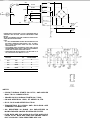
NOTES:
-THIS CIRCUIT STARTS SN 1 2 75 1 , AND AP
PLIES TO SCHEMATIC MI-247C, MI-247D.
-C7 ADDED SN1 6,776. 01 1 5 , 02 1 5 ADDED SN 17526.
--SCHEMATIC DESIGNATIONS PRECEDED BY 1
A R E LEFT CHANNEL; BY 2 , RIGHT CHANNEL.
-VAlUES SHOWN ONLY FOR LEFT CHANNEL
ORG
1
-u SW1
POWER
f1
"'
F2
2A
'
AC
.50-.WO HZ
-
WHT
-
JUMPER
GRN
��, ;
'-
rh
L/
BlU-WHT
c
BlK
r--..
BLK-WHT
E
31
"
T'
WHT
?-r-RED/YEL
>-
'
'
'
�ED- GRN
I
-
'"
>'
'
'
DM-1
:� !
-
o.u
-- - - -1
- - - - - -
REO-BlK
D
1
I
>-
'
>-REDIYEL
----
BLU
>-
BLK
�ED 'GRN
RED
_ _ _ _ _ I
=i=
+
=F=
+
>30
C23
10,000
40V
GND
C24
10,000
40V
R34
1
POWER SUPPLY WIRED FOR 120 VAC. FOR OPERATION AT
AN OTHER LINE VOLTAGE, FOLLOW CONVERSION TABLE
BELOW.
r.7
SELECT THE CORRECT VOLTAGE; CAREFULLY IDENTiFY ALL
WIRES BEFORE PROCEEDING.
NOTE:
- All SIX TRANSFORMER WIRES ARE SOLDERED TO A N
ADJACENT TERM INAL STRIP (POINTS A, B, C, D , AND E).
ONLY FOUR WIRES ARE USED FOR ANY VOLTAGE
CONFIGURATION.
....
- THE JUMPER WIRE. THE ORG AC WIRE. AND THE WHT
TRANSFORMER WIRE ARE All DRAWN WITH ARROWS.
THESE ARE THE ONLY WIRES THAT MOVE. �
- FOR OPERATION BELOW 200VAC. THE LINE FUSE F2. IS
2A; F OR 200VAC A ND ABOVE, F2 IS 1A .
LINE
VOLTAGE
JUMPER
ORG
WHT
AC
TRANSFORMER
100
B-C
c
120
D-E
E
200
NONE
A
A
c
B
220
NONE
c
0
240
NONE
E
D
IIII'UI
LIH
OUT""!
lOQI
,
000 IOI!�TING
OMiiUOMG
-••
'""'T '
1
0
2
3
4
•
•
'
14
13
12
11
10
9
.
"/C" Pin
Numbers
(Top View}
NOTES:
- CI R CU I T SHOWN STARTS SN 1 2751 , A N D APPLIES
O N LY TO P.C. BOARD #7925.
- POWER SUPPLY SHOWN STARTS S N 1 7 ,526 .
- C6 WAS ADDED S N 1 355 1 ; C7 ADDED 1 6,776.
- 01 1 5, 02 1 5 WAS ADDED SN 1 7526.
- TRANSISTORS
01 1 4-0108
AND
021 4-0208
ARE
T H E R MALLY C O N N ECTED.
- ALL
R ESISTORS
IN
OHMS.
ALL CAPACITORS
IN
M I C R O - FARADS U N LESS OTHERWISE STATED.
- R 1 35, R235 A R E 3.3K WHEN IC I S uA749. WHEN IC IS
uA739, R 1 35, R235 ARE O M ITTED UNLESS I N STA
B I LITY OCCURS. THEN R ESISTORS A R E 1 0K.