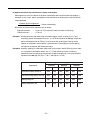
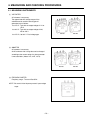
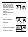
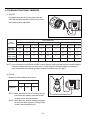
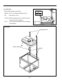
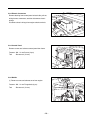
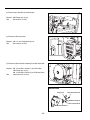
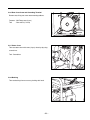
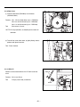
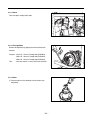
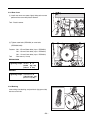
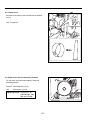
1
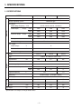
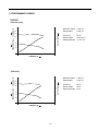
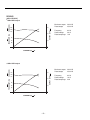
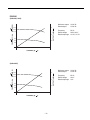
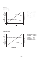
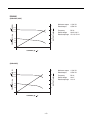
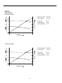
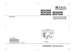
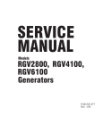
SERVICE
MANUAL
Models
RGX2900
RGX3600
RGX4800
GENERATORS
PUB-GS2102
Rev. 05/06
CONTENTS
Section
Title
Page
1. SPECIFICATIONS
1-1 SPECIFICATIONS . . . . . . . . . . . . . . . . . . . . . . . . . . . . . . . . . . . . . . . . . . . . . . . . . . 1
1-2 PERFOMANCE CURVES . . . . . . . . . . . . . . . . . . . . . . . . . . . . . . . . . . . . . . . . . . . . 2
2. GENERAL DESCRIPTION
2-1 EXTERNAL VIEW . . . . . . . . . . . . . . . . . . . . . . . . . . . . . . . . . . . . . . . . . . . . . . . . . . 8
2-2 CONTROL PANEL . . . . . . . . . . . . . . . . . . . . . . . . . . . . . . . . . . . . . . . . . . . . . . . . . 9
2-3 ALTERNATOR . . . . . . . . . . . . . . . . . . . . . . . . . . . . . . . . . . . . . . . . . . . . . . . . . . . . .11
2-4 LOCATION OF SERIAL NUMBER AND PRODUCTION NUMBER . . . . . . . . . . . .12
3. RANGE OF APPLICATIONS . . . . . . . . . . . . . . . . . . . . . . . . . . . . . . . . . . . . . . . . . . . . .13
4. MEASURING AND CHECKING PROCEDURES
4-1 MEASURING INSTRUMENTS . . . . . . . . . . . . . . . . . . . . . . . . . . . . . . . . . . . . . . . .16
4-2 AC OUTPUT MEASURING . . . . . . . . . . . . . . . . . . . . . . . . . . . . . . . . . . . . . . . . . . .19
4-3 DC OUTPUT MEASURING . . . . . . . . . . . . . . . . . . . . . . . . . . . . . . . . . . . . . . . . . . .19
4-4 MEASURING INSULATION RESISTANCE . . . . . . . . . . . . . . . . . . . . . . . . . . . . . . .20
4-5 CHECKING FUNCTIONAL MEMBERS . . . . . . . . . . . . . . . . . . . . . . . . . . . . . . . . .21
5. DISASSEMBLY AND ASSEMBLY
5-1 PREPARATION AND PRECAUTIONS . . . . . . . . . . . . . . . . . . . . . . . . . . . . . . . . . .25
5-2 DISASSEMBLY PROCEDURES . . . . . . . . . . . . . . . . . . . . . . . . . . . . . . . . . . . . . . .26
5-3 REASSEMBLY PROCEDURES . . . . . . . . . . . . . . . . . . . . . . . . . . . . . . . . . . . . . . .34
6. TROUBLE SHOOTING . . . . . . . . . . . . . . . . . . . . . . . . . . . . . . . . . . . . . . . . . . . . . . . . .42
7. WIRING DIAGRAM . . . . . . . . . . . . . . . . . . . . . . . . . . . . . . . . . . . . . . . . . . . . . . . . . . . .45
This manual covers only alternator and control unit portion of the generator.
As to the servicing information of engine portion, please refer to the “EX series” service manual.
The specifications and information included in this manual were in effect at the time of printing.
FUJI HEAVY INDUSTRIES LTD. reserve the right to change the specifications and to make modifications in the course of
technical progress, at anytime without notice.
No parts of this manual may be reproduced without written permission.
1. SPECIFICATIONS
1-1 SPECIFICATIONS
MODEL
RGX3600
RGX2900
RGX4800
Brush-less, self-exciting, 2-poles, single phase
Type
Voltage regulating system
Condenser type
AC Output
220-50, 240-50, 230-50, 120/240-60
Rated voltage-Frequency V-Hz
Generator
Rated output
Maximum output
VA (W)
VA (W)
50Hz
2000
2400
3500
60Hz
2400
2900
4100
50Hz
2400
3000
4100
60Hz
2900
3600
4800
Rated power factor
1.0
Safety device type
Fuse-less circuit breaker
DC Output
Rated voltage
V
12
Rated current
A
8.3
Safety device type
Fuse-less circuit breaker
169
mL
211
Engine
Fuel
L
Rated continuous operation
H
16.6
50Hz
12
9.5
7
60Hz
10.5
8.4
6
L
1.0
0.6
Spark plug
BR-6HS (NGK) (Champion; RL86C)
Starting system
Dimension
265
Automotive Unleaded Gasoline
Fuel tank capacity
Engine oil capacity
EX27D
ROBIN, Air-cooled, 4-stroke, OHC
Type
Displacement
EX21D
EX17D
Model
Recoil starter
Length
mm
580
605
650
Width
mm
420
450
510
Height
mm
480
500
540
kg
48
54
70
Dry weight
Specifications are subject to change without notice.
–1–
1-2 PERFOMANCE CURVES
RGX2900
230
3.0
220
210
2.0
52
50
1.0
OUTPUT (kVA)
FREQUENCY (Hz)
VOLTAGE (V)
(50Hz-220, 230V)
Maximum output
Rated output
2,400 VA
2,000 VA
Frequency
Rated voltage
Rated amperage
50 Hz
220V, 230 V
9.1 A, 8.7 A
Maximum output
Rated output
2,400 VA
2,000 VA
Frequency
Rated voltage
Rated amperage
50 Hz
240 V
8.3 A
48
0
0
5
10
CURRENT (A)
250
3.0
240
230
2.0
52
50
1.0
48
0
0
5
10
CURRENT (A)
–2–
OUTPUT (kVA)
FREQUENCY (Hz)
VOLTAGE (V)
(50Hz-240V)
RGX2900
250
3.0
240
230
2.0
62
60
1.0
OUTPUT (kVA)
FREQUENCY (Hz)
VOLTAGE (V)
(60Hz-120/240V)
● 60Hz-240V output
Maximum output
Rated output
2,900 VA
2,400 VA
Frequency
Rated voltage
Rated amperage
60 Hz
240 V
10 A
Maximum output
Rated output
2,900 VA
2,400 VA
Frequency
Rated voltage
Rated amperage
60 Hz
120 V
20 A
58
0
0
5
10
15
CURRENT (A)
130
3.0
120
110
2.0
62
60
1.0
58
0
0
10
20
CURRENT (A)
–3–
OUTPUT (kVA)
VOLTAGE (V)
60Hz-120V output
FREQUENCY (Hz)
●
RGX3600
230
3.0
220
210
2.0
52
50
1.0
OUTPUT (kVA)
FREQUENCY (Hz)
VOLTAGE (V)
(50Hz-220, 230V)
Maximum output
Rated output
3,000 VA
2,400 VA
Frequency
Rated voltage
Rated amperage
50 Hz
220V, 230 V
10.9 A, 10.4 A
Maximum output
Rated output
3,000 VA
2,400 VA
Frequency
Rated voltage
Rated amperage
50 Hz
240 V
10 A
48
0
0
5
10
15
CURRENT (A)
250
3.0
240
230
2.0
52
50
1.0
48
0
0
5
10
15
CURRENT (A)
–4–
OUTPUT (kVA)
FREQUENCY (Hz)
VOLTAGE (V)
(50Hz-240V)
RGX3600
250
3.0
240
230
2.0
62
60
1.0
OUTPUT (kVA)
FREQUENCY (Hz)
VOLTAGE (V)
(60Hz-120/240V)
● 60Hz-240V output
Maximum output
Rated output
3,600 VA
2,900 VA
Frequency
Rated voltage
Rated amperage
60 Hz
240 V
12.1 A
Maximum output
Rated output
3,600 VA
2,900 VA
Frequency
Rated voltage
Rated amperage
60 Hz
120 V
24.2 A
58
0
0
5
10
15
CURRENT (A)
130
3.0
120
110
2.0
62
60
1.0
58
0
0
10
20
30
CURRENT (A)
–5–
OUTPUT (kVA)
VOLTAGE (V)
60Hz-120V output
FREQUENCY (Hz)
●
RGX4800
5.0
230
4.0
220
210
3.0
52
2.0
50
48
OUTPUT (kVA)
FREQUENCY (Hz)
VOLTAGE (V)
(50Hz-220V,230V)
Maximum output
Rated output
4,100 VA
3,500 VA
Frequency
Rated voltage
Rated amperage
50 Hz
220V, 230 V
15.9 A, 15.2 A
Maximum output
Rated output
4,100 VA
3,500 VA
Frequency
Rated voltage
Rated amperage
50 Hz
240 V
14.6 A
1.0
0
0
4
8
12
16
20
CURRENT (A)
5.0
250
4.0
240
230
3.0
52
2.0
50
48
1.0
0
0
4
8
12
16
20
CURRENT (A)
–6–
OUTPUT (kVA)
FREQUENCY (Hz)
VOLTAGE (V)
(50Hz-240V)
RGX4800
5.0
250
4.0
240
230
3.0
62
2.0
60
58
OUTPUT (kVA)
FREQUENCY (Hz)
VOLTAGE (V)
(60Hz-120/240V)
● 60Hz-240V output
Maximum output
Rated output
4,800 VA
4,100 VA
Frequency
Rated voltage
Rated amperage
60 Hz
240 V
17.1 A
Maximum output
Rated output
4,800 VA
4,100 VA
Frequency
Rated voltage
Rated amperage
60 Hz
120 V
34.2 A
1.0
0
0
4
8
12
16
20
CURRENT (A)
5.0
130
4.0
120
110
3.0
62
2.0
60
58
1.0
0
0
8
16
24
32
40
CURRENT (A)
–7–
OUTPUT (kVA)
VOLTAGE (V)
60Hz-120V output
FREQUENCY (Hz)
●
2. GENERAL DESCRIPTION
2-1 EXTERNAL VIEW
Engine switch
Fuel tank
Fuel strainer
(Fuel cock)
Control panel
Recoil starter
handle
Recoil starter
Oil gauge (oil filler)
Oil drain plug
Fuel gauge
Tank cap
Spark plug cap
Choke lever
Air cleaner
Muffler cover
Exhaust outlet
–8–
2-2 CONTROL PANEL
RGX2900
(50Hz-220V, 240V)
RGX2900
(60Hz-120/240V)
AC receptacle
AC receptacle
Voltmeter
Voltmeter
AC circuit
breaker
DC output
terminal
DC circuit
breaker
AC circuit
breaker
Earth (ground)
terminal
RGX3600
(50Hz-220V, 240V)
DC output
terminal
DC circuit
breaker
RGX3600
(60Hz-120/240V)
AC receptacle
DC output
terminal
DC circuit
breaker
AC receptacle
Voltmeter
Voltmeter
AC circuit
breaker
AC circuit
breaker
Earth (ground)
terminal
RGX4800
(50Hz-220V, 240V)
DC output
terminal
DC circuit
breaker
Earth (ground)
terminal
RGX4800
(60Hz-120/240V)
AC receptacle
AC receptacle
Voltmeter
DC circuit
breaker
Full power
switch
Voltmeter
AC circuit
breaker
DC output
terminal
Earth (ground)
terminal
AC circuit
breaker
Earth (ground)
terminal
DC output
terminal
–9–
DC circuit
breaker
Earth (ground)
terminal
RGX2900
(50Hz-230V)
AC receptacle
Voltmeter
AC circuit
breaker
DC output
terminal
DC circuit
breaker
Earth (ground)
terminal
RGX3600
(50Hz-230V)
AC receptacle
Voltmeter
AC circuit
breaker
DC output
terminal
DC circuit
breaker
Earth (ground)
terminal
RGX4800
(50Hz-230V)
AC receptacle
Voltmeter
AC circuit
breaker
DC output
terminal
DC circuit
breaker
Earth (ground)
terminal
– 10 –
2-3 ALTERNATOR
RGX2900/3600
Rotor CP
Cover bolt
Stator CP
Ball bearing
Crank shaft
Rotor bolt
Rear cover
Mount rubber
Stator cover
Front cover
RGX4800
Ball bearing
Cover bolt
Rotor CP
Stator CP
Rotor bolt
Mount rubber
Rear cover
Crank shaft
Stator cover
– 11 –
Front cover
2-4 LOCATION OF SERIAL NUMBER AND PRODUCTION NUMBER
Generator serial number and production number are stamped on the label stuck on the side of fuel tank.
PROD No. / SER No. (Label)
NOTE : When inquiring about your generator or ordering spare parts, always give us the Model, Serial
Number and Production Number.
– 12 –
3. RANGE OF APPLICATIONS
Generally, the power rating of an electrical appliance indicates the amount of work that can be done by it.
The electric power required for operating an electrical appliance is not always equal to the output wattage
of the appliance. The electrical appliances generally have a label showing their rated voltage, frequency,
and power consumption (input wattage). The power consumption of an electrical appliance is the power
necessary for using it. When using a generator for operating an electrical appliance, the power factor and
starting wattage must be taken into consideration.
In order to determine the right size generator, it is necessary to add the total wattage of all appliances to
be connected to the unit.
Refer to the followings to calculate the power consumption of each appliance or equipment by its type.
(1) Incandescent lamp, heater, etc. with a power factor of 1.0
Total power consumption must be equal to or less than the rated output of the generator.
Example : A rated 3000W generator can turn thirty 100W incandescent lamps on.
(2) Fluorescent lamps, motor driven tools, light electrical appliances, etc. with a smaller power factor
Select a generator with a rated output equivalent to 1.2 to 2 times of the power consumption of the
load. Generally the starting wattage of motor driven tools and light electrical appliances are 1.2 to 3
times lager than their running wattage.
Example : A rated 250 W electric drill requires a 400 W generator to start it.
NOTE 1: If a power factor correction capacitor is not applied to the fluorescent lamp, the more power
shall be required to drive the lamps.
NOTE 2: Nominal wattage of the fluorscent lamp generally indicates the output wattage of the lamp.
Therefore, if the fluorescent lamp has no special indication as to the power consumption,
efficiency should be taken into account as explained in ltem (5) on the following page.
(3) Mercury lamps with a smaller power factor
Loads for mercury lamps require 2 to 3 times the indicated wattage during start-up.
Example : A 400 W mercury lamp requires 800 W to 1200 W power source to be turned on. A rated
3000 W generator can power two or three 400 W mercury lamps.
(4) Initially loaded motor driven appliances such as water pumps, compressors, etc.
These appliances require large starting wattage which is 3 to 5 times of running wattage.
Example : A rated 900 W compressor requires a 4500 W generator to drive it.
NOTE 1: Motor-driven appliances require the aforementioned generator output only at the starting.
Once their motors are started, the appliances consume about 1.2 to 2 times their rated power
consumption so that the excess power generated by the generator can be used for other
electrical appliances.
NOTE 2: Motor-driven appliances mentioned in items (3) and (4) vary in their required motor starting
power depending on the kind of motor and start-up load. If it is difficult to determine the
optimum generator capacity, select a generator with a larger capacity.
– 13 –
(5) Appliances without any indication as to power consumption
Some appliances have no indication as to power consumption; but instead the work load (output) is
indicated. In such a case, power consumption is to be worked out according to the numerical formula
mentioned below.
(Output of electrical appliance)
= (Power consumption)
(Efficiency)
Efficiencies of some electrical appliances are as follows :
Single-phase motor . . . . . .0.6 to 0.75 (The smaller the motor, the lower the efficiency)
Fluorescent lamp . . . . . . . .0.7 to 0.8
Example 1: A 40W fluorescent lamp means that its luminous output is 40W. Its efficiency is 0.7 and
accordingly, power consumption will be 40÷0.7= 57W. As explained in Item (2), multiply this
power consumption value of 57W by 1.2 to 2 and you will get the figure of the necessary
capacity of a generator. In other words, a generator with a rated output of 1000W capacity
can light nine to fourteen 40W fluorescent lamps.
Example 2: Generally speaking, a 400W motor means that its work load is 400W. Efficiency of this motor
is 0.7 and power consumption will be 400÷0.7= 570W. When this motor is used for a
motor-driven tool, the capacity of the generator should be multipled by 1.2 to 3 and 570W as
explained in the ltem (3). 570 (W) x 1.2 to 3 = 684 (W) to 1710 (W)
Applicable Wattage (approx. W)
Applications
RGX2900
RGX3600
RGX4800
50Hz
60Hz
50Hz
60Hz
50Hz
60Hz
Incandescent lamp, Heater, etc
2000
2400
2400
2900
3500
4100
Fluorescent lamp, Electric tool, etc
1100
1200
1200
1500
1800
2100
Mercury lamp, etc
800
900
900
1100
1300
1500
Pump, Compressor, etc
500
550
550
650
800
950
– 14 –
NOTES : Wiring between generator and electrical appliances
1. Allowable current of cable
Use a cable with an allowable current that is higher than the rated input current of the load (electrical
appliance). If the input current is higher than the allowable current of the cable used, the cable will
become excessively heated and deteriorate the insulation, possibly burning it out. The table below
shows cables and their allowable currents for your reference.
2. Cable length
If a long cable is used, a voltage drop occurs due to the increased resistance in the conductors
decreasing the input voltage to the load (electrical product). As a result, the load can be damaged.
The table below shows voltage drops per 30 meters of cable.
Cross
sectional
mm2
Allowable
Current
A
Cable
Resistance
Ω/100m
5A
10A
15A
20A
25A
30A
1.25
12
1.486
4.5V
8.9V
*
*
*
*
2.0
17
0.952
2.8V
5.7V
8.6V
*
*
*
3.5
23
0.517
1.6V
3.1V
4.7V
6.2V
*
*
5.5
35
0.332
1.0V
2.0V
3.0V
4.0V
5.0V
6.0V
Voltage drop indicates as V=
Voltage drops per 30 meters of cable
1
xRxIxL
100
R : Resistance (Ω/100m)
I : Electric current (A)
L : Length (m)
The length of wire (L) indicates round length, which is the length from the generator
to the electrical tools and back.
<Example>
R : Resistance 1.25mm2 = 1.48 Ω/100m
I : Electric current 10A
L : Length 30m
The voltage drop of the case described above is
V = 1.48Ω x 10A x (30m x 2) ≒ 8.9 (V)
100
– 15 –
4. MEASURING AND CHECKING PROCEDURES
4-1 MEASURING INSTRUMENTS
(1) VOLTMETER
AC voltmeter is necessary.
The approximate AC voltage ranges of the
voltmeters to be used for various types of
generators are as follows :
0 to 150 V : Type with an output voltage of 110 or
120 V
0 to 300 V : Type with an output voltage of 220,
230 or 240 V
0 to 150 V, 0 to 330 V : Dual voltage type
For AC
For DC
(2) AMMETER
AC ammeter is necessary.
An AC ammeter with a range that can be changed
according to the current rating of a given generator
is most desirable. (About 10 A, 20 A, 100 A)
For AC
(3) FREQUENCY METER
Frequency range : To cover 45 to 65Hz
NOTE : Be careful of the frequency meter's input voltage
range.
– 16 –
For DC
(4) CIRCUIT TESTER
For measuring resistance, etc.
NOTE : The ordinary circuit tester may cause erroneous
readings due to their measuring method.
Use a high-grade, precise circuit tester to check
the generator components.
(5) MEAGER TESTER
Used for measuring generator insulation resistance.
Select the one with testing voltage range of 500V.
(6) TACHOMETER
Use the contactless type tacho meter for checking
engine speed.
– 17 –
(7) "Dr.Robin" GENERATOR TESTER
The "Dr.Robin" generator tester is exclusively
designed for fast, easy diagnosis and repair of
Robin generators.
The "Dr.Robin" has the following features :
1) Functions of voltmeter, frequency meter, megger
tester, capacitance meter and circuit tester are
combined in one unit.
2) Fast and easy readout by digital indicator.
3) Built-in automatic battery checker indicates the
time to change batteries.
4) Tester and accessories are installed in a handy,
sturdy case for easy carrying.
●
SPECIFICATIONS
MODEL
Dr.Robin
388-47565-08
Part Number
Voltage
Measuring
Range
0 to 500 V AC
Frequency
25 to 70 Hz
Resistance
0.1 to 1,999 Ω
Condenser Capacity
10 to 100μF
Insulation Resistance
3MΩ
Circuit Protector
Fuse
Power Source
2 x 6F44P (006P) Dry Cell Battery
Test leads with needle probes ... 1 set
Test leads with jack plugs ... 1 set
Accessories
Dimensions (L x W x H)
285 mm x 200 mm x 110 mm
Weight
1.6 kg
The "Dr.Robin" generator tester can be ordered from Robin generator distributors by the following part number.
Dr.Robin_Part_Number_:_388-47565-08
If you do not have a "Dr.Robin" generator tester, use the instruments described in the following section for
checking generator parts.
– 18 –
4-2 AC OUTPUT MEASURING
SWITCH
LOAD
A
~
V
~
F
TO AC RECEPTACLE
Use a circuit above for measuring AC output. A hot plate or lamp with a power factor of 1.0 may be used as a
load. Adjust the load and rpm, and check that the voltage range is as specified in the following table at the
rated amperage and rated rpm.
Specification
50Hz-220V,230V
50Hz-240V
60Hz-120/240V
207-238
226-259
226-259
113-130
RGX2900
RGX3600
RGX4800
Voltage range
Model
4-3 DC OUTPUT MEASURING
SW
Load
To DC Terminal
Measurement of DC output is executed with the switch turned ON while the current is regulated at 8.3A by
adjusting the load to the generator. If the voltage is within the range from 6V to 14V, the voltage output is
normal.
NOTE : If a battery is connected as a load to the generator, the DC output voltage will increase by
approximately 1 to 2 V.
Therefore, carefully observe the electrolyte level and do not overcharge the battery.
– 19 –
4-4 MEASURING INSULATION RESISTANCE
Use a “Dr. Robin” generator tester in megger tester
mode or use a megger tester to check the insulation
resistance. Connect a megger tester to one of
receptacle output terminals and the ground terminal,
then measure the insulation resistance. An insulation
resistance of 1 megohm or more is normal. (The original
insulation resistance at the time of shipment from the
factory is 10 megohm or more.) If it is less than 1
megohm, disassemble the generator and measure the
insulation resistance of the stator, rotor and control
panel individually.
Any part where the insulation resistance is less than 1M
Ω has faulty insulation, and may cause electric leakage
and electric shock.
Replace the faulty part.
●
STATOR
Measure insulation resistance between each terminal
from the stator and the stator core.
Measured insulation resistance of 1M ohm or
more is normal.
If it is less than 1M ohm, leakage current and
electric shock might occur due to faulty insulation.
Replace with new one.
●
CONTROL PANEL
With AC circuit breaker turned on, measure insulation
resistance between each portion of electrical parts
and earth (grounding) terminal or control panel itself.
Measured insulation resistance of 1M ohm or
more is normal.
If it is less than 1M ohm, leakage current and electric
shock might occur due to faulty insulation.
Replace with new one.
– 20 –
4-5 CHECKING FUNCTIONAL MEMBERS
(1) STATOR
Disengage connectors on the wires from stator and
check the resistance between the wires using a circuit
tester referring to the table below.
Coil resistance (Ω)
Coils
(Wire color)
AC coil 1
(Black - Blue)
AC coil 2
(Red - White)
Condenser coil
(Yellow - Yellow)
DC coil
(Brown - Brown)
RGX2900
50Hz-220V
50Hz-230V
RGX3600
RGX4800
50Hz-220V
50Hz-220V
50Hz-240V 60Hz-120/240V 50Hz-230V 50Hz-240V 60Hz-120/240V 50Hz-230V
50Hz-240V 60Hz-120/240V
0.8
0.9
0.6
0.6
0.7
0.4
0.4
0.4
0.3
0.8
0.9
0.6
0.6
0.7
0.4
0.4
0.4
0.3
2.2
2.2
1.7
1.3
1.3
1.0
0.9
0.9
0.6
0.3
0.3
0.2
0.2
0.2
0.2
0.2
0.2
0.1
NOTE : If the circuit tester is not sufficiently accurate, it may not show the values given and may give erroneous readings.
Erroneous readings will also occur when there is a wide variation of resistance among coil windings or
when measurement is performed at ambient temperature different from 20°
C (68°
F).
(2) ROTOR
Measure resistance between the field coil.
Coil resistance (Ω)
Field coil
RGX2900
RGX3600
RGX4800
1.8
1.6
1.6
NOTE1 : When measuring the field coil resistance, be sure
to disconnect the soldering connection and take
out diode rectifier and surge absorber.
NOTE2 : When measuring, tolerance should be considered
because of the tester inaccuracy, winding number
variation, ambient temperature etc.
– 21 –
The diode rectifier and surge absorber are located as
RGX2900/3600
shown in the following illustrations.
SURGE ABSORBER
RGX4800
SURGE ABSORBER
(3) SURGE ABSORBER
Measure the surge absorber resistance.
Resistance (Ω)
∞Ω
– 22 –
DIODE RECTIFIER
DIODE
RECTIFIER
(4)AC CIRCUIT BREAKER
Check continuity between each of two terminals at the
rear of the AC circuit breaker while it is mounted on
the control panel.
RGX2900
RGX3600/4800
A
A
B
B
AC circuit breaker
OFF:No continuity
ON :Continuity
(5) DC CIRCUIT BREAKER
Make sure that there is continuity between the two
terminals of DC circuit breaker when its push button
is pressed.
– 23 –
(6) CONDENSER
Use "Dr. ROBIN" in capacitance mode to check the
capacity of condenser.
NOTE: Be sure to discharge by shorting condenser leads
each other before checking the capacitance, or the
accurate reading cannot be obtained.
If such instrument is unavailable, the condenser can be
checked by replacing with new one.
If the generator performs good with new condenser, the
cause of trouble is defect in original condenser.
MODEL
RGX2900
RGX3600
RGX4800
CAPACITY(μF)
24
37
20 and 30
(8) AC RECEPTACLES
Make sure that no live part wire or plastic part is burnt out.
(9) FLOAT TYPE OIL SENSOR
Check the oil sensor when it is installed on the engine.
Check that sufficient engine oil is filled in the crankcase.
Check that there is continuity between the lead wire of
oil sensor and the ground (engine crankcase) when the
oil level is above the minimum level mark of oil gauge.
Check that there is no continuity as above when the oil
level is below the minimum level mark of oil gauge.
– 24 –
Oil sensor
5. DISASSEMBLY AND ASSEMBLY
5-1 PREPARATION AND PRECAUTIONS
(1) Be sure to memorize the location of individual parts when disassembling the generator so that the generator
can be reassembled correctly. Tag the disassembled part with the necessary information to facilitate easier and
smoother reassembly.
(2) For more convenience, divide the parts into several groups and store them in boxes.
(3) To prevent bolts and nuts from being misplaced or installed incorrectly, replace them temporarily to their
original position.
(4) Handle disassembled parts with care; clean them before reassembly using a neutral cleaning fluid.
(5) Remove the battery before disassembling the generator. (Electric start models)
(6) Use all disassembly/assembly tools properly, and use the proper tool for each specific job.
(7) Be sure to attach the foam rubber linings inside the covers on their original position when reassembling the
generator. When deformation or damage or falling-off of foam rubber lining is found, replace it with new part.
Failure to do so will result in poor performance and durability of the generator.
(8) Bind the wires and fuel pipes using wire bands as they have been done in original configuration.
NOTE : As to detailed information for servicing procedures on engine portion, please refer to Robin engine service
manual for "EX series".
NOTE : Illustrations adopted for the following procedures are ones for RGX4800 model.
Also illustrations for RGX2900/3600 are adopted as necessary.
– 25 –
5-2 DISASSEMBLY PROCEDURES
5-2-1 Fuel Draining
(1) Make sure fuel strainer cock is closed.
Disconnect fuel pipe from carburetor.
Turn fuel cock lever to the OPEN position, and the drain
fuel from fuel tank.
Tool
: Pliers
(2) Remove drain screw from carburetor, and drain fuel
from carburetor.
After draining, install drain screw in position.
Tool
: Socket wrench (8 mm)
Drain screw
(3) Remove strainer and drain fuel from strainer cap.
After draining, install strainer in position.
– 26 –
5-2-2 Fuel Tank
Cussion rubber
Remove bolts and take out fuek tank.
Fastener : M6 -12 mm Flange reamer bolts (2 pcs)
Tool
: Box wrench (10 mm)
CAUTION : Before removing fuel tank, make sure to drain
fuel from fuel tank and pipings.
NOTE
: Don't forget to keep rubbers (2 pcs) commonly
fixed with bolts.
Control panel
side
Fuel tank
Frange reamer bolt
Cussion rubber
Rubber
– 27 –
5-2-3 Electric Connectors
Remove bushing from control panel on back side, pull out
wiring harness connectors, and then disconnect electric
wirings.
Disconnect electric wirings from engine switch terminals.
5-2-4 Control Panel
Remove screws and take out control panel from frame.
Fastener : M6 - 12 mm Screws (4 pcs)
Tool
: Box wrench (10 mm)
5-2-5 Muffler
(1) Remove screws and take out cover from engine.
Fastener : M6 - 12 mm Flange bolts (3 pcs)
Tool
: Box wrench (10 mm)
– 28 –
(2) Remove nuts and take out exhaust pipe.
Fastener : M8 Flange nuts (2 pcs)
Tool
: Box wrench (12 mm)
(3) Remove muffler and cover.
Fastener : M8 - 10 mm Flange bolts (6 pcs)
Tool
: Box wrench (12 mm)
(4) Remove muffler bracket commonly fixed with alternator.
Fastener : M8 - 20 mm Bolt & washers (2 pcs-RGX 4800)
M8 Flange nuts (2 pcs)
M8 - 20 mm Bolt & washers (4 pcs-RGX 2900/3600)
Tool
: Socket wrench (12 mm)
RGX2900/3600
Frange nut
Bolt and washer AY
Muffler bracket B
Bolt and washer AY
Muffler bracket A
– 29 –
5-2-6 Rear Cover Arms and Grounding Terminal
Remove nuts fixing rear cover onto mounting rubbers.
Fastener : M8 Flange nuts (2 pcs)
Tool
: Box wrench (12 mm)
Grounding
Terminal
5-2-7 Stator Cover
Take out stator cover with crows (2 pcs) raised up by using
screw driver.
Tool : Screwdriver
5-2-8 Bushing
Take out bushing from rear cover, pinching with hand.
– 30 –
5-2-9 Rear Cover
(1) Remove stator bolts (RGX4800) or cover bolts
(RGX2900/3600).
Fastener : M6 - 150 mm Stator bolts (4 pcs - RGX4800)
M6 -130 mm Cover bolts (3 pcs - RGX3600)
M6 -110 mm Cover bolts (3 pcs - RGX2900)
Tool
: Box wrench (12 mm)
NOTE: For easy operation, set wooden pieces under the
alternator.
(2) Take off rear cover from stator, by lightly hitting at boss
portions with plastic hammer.
Tool : Plastic hammer
5-2-10 Wire CP
Remove screw and disconnect wire CP from inside rear
cover.
Wire CP
Fastener : M4 -6 mm Screw
Tool
: Philips (cross-head) screwdriver
Screw
– 31 –
5-2-11 Stator
Take out stator, holding with hands.
5-2-12 Through Bolts
Remove through bolt, by tapping the wrench with plastic
hammer.
Fastener : M10x1.5 - 240 mm Through bolt (RGX4800)
M8x1.25 - 260 mm Through bolt (RGX3600)
M8x1.25 - 240 mm Through bolt (RGX2900)
Tool
: Box-end wrench (14 mm) and Plastic hammer
5-2-13 Rotor
(1) Set the engine in the condition of recoil starter side
downward.
– 32 –
(2) Use engine oil and the bolt with seal tape as a tool for
pulling out rotor as follows;
a. Pour engine oil into the center (through bolt) hole of rotor
shaft.
b. prepare a bolt with the following thread size;
Model
Bolt
RGX4800
M12×1.5
RGX2900
RGX3600
M10×1.5
Seal tape
c. Apply a few turns of seal tape around the tip of the bolt.
d. Screw the bolt into the thread of the rotor shaft.
e. Torque up the bolt by using socket wrench until rotor
comes off loose.
NOTE: The hydraulic pressure inside the rotor shaft takes
apart the rotor from the engine PTO shaft.
f. Wipe off engine oil thoroughly from rotor, rotor shaft,
engine PTO shaft and front cover.
5-2-14 Front Cover
Remove bolts and washers and take out front cover.
Fastener : M8 - 20 mm Bolt & washers (4 pcs)
Tool
: Box-end wrench (12 mm)
– 33 –
5-3 REASSEMBLY PROCEDURES
5-3-1 Front Cover
Install front cover onto main bearing cover of the engine in
position.
Fastener :
M8 - 20 mm (4 pcs) Bolt with spring washer & washer
Tightening torque : 11.8-13.7 N・m
(120-140 kgf・cm)
(8.7-10.1 ft・lbs)
5-3-2 Rotor
Install rotor onto crankshaft.
Fastener :
M8x1.25 - 240 mm Through bolt with washer (RGX2900)
M8x1.25 - 260 mm Through bolt with washer (RGX3600)
M10x1.5 - 240 mm Through bolt with washer (RGX4800)
RGX2900/3600
Tightening torque : 11.3-13.2 N・m
(115-135 kgf・cm)
(8.3-9.7 ft・lbs)
RGX4800
Tightening torque : 22.5-24.5 N・m
(230-250 kgf・cm)
(16.6-18.1ft・lbs)
NOTE: Before installing, clean and wipe off oil and foreign
materials from taper portion of crankshaft.
– 34 –
5-3-3 Stator
Install stator into front cover.
Adjust the stator grove position (4 places) so that stator bolt
can be tightened later. (RGX4800)
(Stator bolt)
Stator bolt
fixed hole(4 places)
Grove
(4 places)
Roter
Stator
Front cover
5-3-4 Wire CP
Fix wire CP at inside of rear cover in position.
Wire CP
Fastener : M4 -6 mm Screw
Tool
: Philips (cross-head) screwdriver
Screw
– 35 –
5-3-5 Rear Cover
(1) Install rear cover over stator, lightly hitting at the center
portion of rear cover with plastic hammer.
Tool : Plastic hammer
(2) Tighten stator bolts (RGX4800) or cover bolts
(RGX2900/3600).
Fastener : M6 - 150 mm Stator bolts (4 pcs - RGX4800)
M6 - 130 mm Cover bolts (3 pcs - RGX3600)
M6 - 110 mm Cover bolts (3 pcs - RGX2900)
Tool
: Box wrench (12 mm)
RGX2900/3600
Tightening torque : 4.5-5.9 N・m
(50-60 kgf・cm)
(3.6-4.3 ft・lbs)
RGX4800
Tightening torque : 11.8-13.7 N・m
(120-140 kgf・cm)
(8.7-10.1 ft・lbs)
5-3-6 Bushing
Insert wirings into bushing, and push bush (big grove side)
into rear cover hole.
– 36 –
5-3-7 Stator Cover
Set stator cover with the crow inserted into slit and bent
(2 pcs).
Tool : Screwdriver
5-3-8 Rear Cover Arm and Grounding Terminal
Fix rear cover arms with mount rubbers, along with
grounding terminal.
Fastener : M8 Flange nuts (2 pcs)
Tool
: Box wrench (12 mm)
Tightening torque : 11.8-13.7 N・m
(120-140 kgf・cm)
(8.7-10.1 ft・lbs)
Grounding
Terminal
– 37 –
5-3-9 Muffler
(1) Install muffler bracket.
Fastener : M8 - 20 mm Bolt & washers (2 pcs - RGX4800)
M8 Flange nuts (2 pcs)
M8 - 20 mm Bolt & washers (4 pcs - RGX2900/3600)
Tool
: Socket wrench (12 mm)
Tightening torque : 11.8-13.7 N・m
(120-140 kgf・cm)
(8.7-10.1 ft・lbs)
(2) Install muffler and cover.
Fastener : M8 - 10 mm Flange bolts (6 pcs)
Tool
: Box wrench (12 mm)
Tightening torque : 11.8-13.7 N・m
(120-140 kgf・cm)
(8.7-10.1 ft・lbs)
(3) Install exhaust pipe.
Fastener : M8 Flange nuts (2 pcs)
Tool
: Box wrench (12 mm)
Tightening torque : 11.8-13.7 N・m
(120-140 kgf・cm)
(8.7-10.1 ft・lbs)
– 38 –
(4) Attach exhaust pipe cover.
Fastener : M6 - 12 mm Flange bolts (3 pcs)
Tool
: Box wrench (10 mm)
Tightening torque : 4.5-5.9 N・m
(50-60 kgf・cm)
(3.6-4.3 ft・lbs)
5-3-10 Control Panel
Fix control panel into frame.
Fastener : M6 - 12 mm Screws (4 pcs)
Tool
: Box wrench (10 mm)
Tightening torque : 4.5-5.9 N・m
(50-60 kgf・cm)
(3.6-4.3 ft・lbs)
5-3-11 Electric Connectors
(1) Connect all wirings of the same appearance each other
between control panel and alternator.
– 39 –
(2) Push into bushing into the hole on the back side of
control panel.
Also connect electric wirings with engine switch
terminals. Either wiring can be connected with terminal.
5-3-12 Fuel Tank
Cussion rubber
(1) Set fuel tank with cushion rubber sliding into stay
(2 places).
Stay
(2) Fix with bolts.
Fastener : M6 -12 mm Flange reamer bolts (2 pcs)
Tool
: Box wrench (10 mm)
Tightening torque : 4.5-5.9 N・m
(50-60 kgf・cm)
(3.6-4.3 ft・lbs)
Control panel
side
– 40 –
5-3-13 Fuel piping
Connect fuel pipe to carburetor with clam.
Fuel pipe
Tool : Pliers
Clamp
Carburetor
– 41 –
6. TROUBLE SHOOTING
Check if engine speed is normal.
50Hz : 3,000rpm
60Hz : 3,600rpm
NG
Refer to
"Engine dose not start (Start failure )"
OK
Check if stator coil is normal.
Main coil
NG
Replace
OK
Check if rotor coil is normal.
NG
Replace
OK
Check if condenser coil is normal.
NG
Replace
OK
Check if wiring is break or
improper connection.
Replace when wiring is break or damage.
NG
Connect properly.
– 42 –
No DC current
Check if DC coil of stator is normal.
NG
Replace
OK
Check if diode rectifier is normal.
NG
Replace
OK
Check if DC circuit breaker is normal.
NG
Replace
OK
Check if wiring is break or
improper connection.
NG
Replace when wiring is break or damage.
Connect properly.
– 43 –
Engine does not start (Start failure)
None
Check the gasoline
in the tank
Add gasoline
Yes
None
Check the oil volume
Add oil (up to the
rated volume)
Yes
Confirm of the oil SW
E/g
GND
Resistance
value≒0 Ω
Change the Oil sensor unit
Tester
Fuel cock is in
the ON position
NO
Open
the cock
NO
Clean,
change
the filter
Yes
Gasoline leaks when the
carburetor drain is loosened
Yes
Check for
gasoline corrosion
Corrosion
Change
gasoline
OK
Remove the spark plug
and check the electrode
Dry
Blockage of the fuel tube
carburetor, such as noise, etc.
No spark
・Check for dirty plugs, or gap
・Check the connection
(coupler, high tension cord)
Wet
Attach the plug to the plug
cap, and check for sparks
by grounding the electrode
Sparks
Check the valve clearance
of the compressed pressure
(compression)
NG
Adjustment
– 44 –
7. WIRING DIAGRAM
(60Hz-120V) RGX2900 [U.S.A. model]
ENGINE
CONTROL BOX
Oil sensor
Wi ring color code
Blk
: Black
Blk/W : Black/White
Blu
: Blue
LBlu : Light blue
Brn : Brown
Brn/W : Brown/White
Grn : Green
Grn/W : Green/White
Org : Orange
Gry : Gray
R
: Red
W
: White
Y
: Yellow
W/Blk : White/Black
Grn/Y : Green/Yellow
Pur : Purple
Engine switch
Blk
Ignition coil
Grn
Spark plug
GENERATOR
AC circuit
breaker
AC
Winding 1
Grn
R
Blk
Earth
(Ground)
terminal
Gry
Pilot
lamp PL
Blu
R
AC
Winding 2
Field
Winding
Rotor
H
Hour Hr
meter
W
Rec
W
Condenser
Winding
Diode stack
Assy
Org
DC
Winding
Brn
Circuit breaker
DC output
terminal
Brn/W
Brn
Y
Condenser
Y
Grn
(60Hz-120/240V) RGX3600 [U.S.A. model]
ENGINE
CONTROL BOX
Oil sensor
Engine switch
Blk
Charge coil
Ignition coil
Spark plug
Grn
Blu
LBlu
W
W
Solenoid
GENERATOR
1
5
AC
Winding 1
AC circuit
breaker
AC
Winding 2
Field
Winding
Rotor
3
2
Idle control switch
DC
Winding
Condenser
Winding
Blk
Pilot PL
lamp
Blu
R
Hour Hr
meter
Idle
control
unit
Full power
switch
1
2
3
5
4
6
8
7
9
H
X
W
W
Y
Diode stack
Assy
Org
Y
X
Circuit breaker
DC output
terminal
Brn/W
Brn
Y
G
W
Rec3
W
Brn
Gry
Rec2
G
Rec1 G
Condenser
Grn
– 45 –
Earth
(Ground)
terminal
(60Hz-120/240V) RGX4800 [U.S.A. model]
ENGINE
CONTROL BOX
Wi ring color code
Oil sensor
Blk
: Black
Blk/W : Black/White
Blu
: Blue
LBlu : Light blue
Brn : Brown
Brn/W : Brown/White
Grn : Green
Grn/W : Green/White
Org : Orange
Gry : Gray
R
: Red
W
: White
Y
: Yellow
W/Blk : White/Black
Grn/Y : Green/Yellow
Pur : Purple
Engine switch
Blk
Charge coil
Spark plug
Grn
Blu
LBlu
3
2
Idle control switch
W
W
Solenoid
GENERATOR
AC circuit
breaker
Full power
switch
1
2
3
AC
Winding 1
Blk
Pilot PL
lamp
Blu
R
AC
Winding 2
Field
Winding
Rotor
Idle
control
unit
1
5
Hour Hr
meter
5
4
6
8
7
9
H
W
X
Diode stack
Assy
Org
DC
Winding
Brn
W
Y
G
X
Circuit breaker
DC output
terminal
Brn/W
Brn
Y
Condenser
Y
Earth
(Ground)
terminal
W
Rec3
W
Condenser
Winding
Gr y
Rec2
G
Rec1 G
Circuit
breaker
Ignition coil
Condenser
Grn
(60Hz-120/240V) RGX4800 w / Starter motor [U.S.A. model]
ENGINE
CONTROL BOX
Battery
Fuse
Oil sensor
Org
Magnetiec switch
Blk
Diode stack
Assy
Charge coil
Ignition coil
Spark plug
Blu
LBlu
W
W
GENERATOR
AC
Winding 1
AC
Winding 2
Field
Winding
1
5
DC
Winding
Blk
Pilot PL
lamp
Blu
R
W
Brn
Hour Hr
meter
3
2
Idle control switch
AC circuit
breaker
Condenser
Winding
B
ST
-M
+M IG
R
Grn
Solenoid
Rotor
Key switch
Y
Grn
Full power
switch
1
2
3
5
8
H
W
7
9
Gry
Rec2
G
Rec1 G
4
6
X
Y
Earth
(Ground)
terminal
W
G
X
W
Rec3
Diode stack
Assy
Org
Circuit breaker
Brn/W
Brn
Y
Idle
control
unit
Circuit
breaker
+
Electric
starter
-
Condenser
DC output
terminal
Condenser
Grn
– 46 –
940 Lively Blvd. • Wood Dale, IL 60191 • Phone: 630-350-8200 • Fax: 630-350-8212
e-mail: [email protected] • www.robinamerica.com
© Copyright 2006 Robin America, Inc.
PRINTED IN THE USA