1
Instruction
Manual
I CRRFTSMRN°I
3.8 Amp Motor
12 Inch Cutting Path/.065
ELECTRIC
In. Line
WEEDWACKER
®
Model No.
358.799201
•
Safety
• Assembly
• Operation
• Maintenance
•
Espa_ol
®
WARNING:
Read and follow all Safety Rules and Operating
Instructions
before first use of this product.
For answers
Call 7 am-7
to your questions about this product:
pm, Mon.-Sat.,
or 10 am-7 pm, Sun.
1-800-235-5878
Sears,
Roebuck
530088743
10/1/01
(Hours listed are Central Time)
and Co., Hoffman
Estates,
IL 60179
U.S.A.
Warranty
2
Parts Available
Safety Rules
Statement
2
Storage
Assembly
Operation
Maintenance
5
6
8
Troubleshooting
Service & Adjustments
8
Parts Ordering
9
9
Table
9
Spanish
10
Back Cover
FULL ONE YEAR WARRANTY ON CRAFTSMAN
ELECTRIC WEEDWACKER ®
LINE TRIMMER
If this Craftsman Electric Weedwacker c_ Line Trimmer fails to perform properly
due to a defect in material or workmanship
within (1) one year from the date of
purchase, Sears will replace it free of charge.
This warranty does not cover the nylon line.
WARRANTY SERVICE IS AVAILABLE BY RETURNING THE CRAFTSMAN ELECTRIC
WEEDWACKER _: LINE TRIMMER TO THE NEAREST SEARS STORE OR SERVICE CENTER IN THE UNITED STATES.
This warranty gives you specific legal rights, and you may also have other rights
which vary from state to state.
Sears, Roebuck and Co., D/817WA, Hoffman Estates, IL 60179
Q@©
_WARNIN_I:
When using electric
gardening appliances, basic safety
precautions must always be followed
to reduce the risk of fire, electric shock,
and serious injury. Read and follow all
instructions.
_"
_WARNIN_I:
Trimmer line throws
objects violently. You and others can
be blinded/injured.
Wear safety
glasses, boots, and leg protection.
Keep body parts clear of rotating line.
Safety glasses or similar eye protection
ON
THE UNIT
SAFETY
INFORMATION
This power unit
The operator is
ing the warnings
this manual and
can be dangerous!
responsible for followand instructions in
on the unit. Read en-
tire instruction manual before using
unit! Be thoroughly familiar with the
controls and the proper use of the unit.
Restrict the use of this unit to persons
who read, understand, and follow unit
and manual warnings and instructions. Never allow children to operate
this unit. Close attention is necessary
when used near children.
Keep children, bystanders, and animals 50 feet (15 meters) away. If approached stop unit immediately.
If situations occur which are not covered in this manual, use care and
good judgement. If you need assistance, call 1-800-235-5878
OPERATOR SAFETY
• Dress properly. Always wear safety
glasses or similar eye protection
when operating, or performing maintenance on your unit. (Safety glasses
are available.) Always wear face or
A
_1_ DANGER:
Never use blades,
wire, or flailing devices. Unit is designed
for line trimmer use only. Use of any other accessories or attachments will increase the risk of injury.
2
dustmaskifoperation
isdusty.
Always
wearheavy,
longpants,
long
sleeves,
boots,
andgloves.
Donot
gobarefoot
orwear
sandals.
• Secure
hairabove
shoulder
length.
Secure
orremove
loose
clothing
and
jewelry
orclothing
withloosely
hangingties,straps,
tassels,
etc.They
canbecaught
inmoving
parts.
• Being
fullycovered
alsohelps
protectyoufromdebris
andpieces
of
toxicplants
thrown
byspinning
line.
• StayAlert.
Donotoperate
unitwhen
youaretired,ill,orunderinfluence
ofalcohol,
drugs,
ormedication.
Watch
what
youaredoing;
usecommonsense.
• Avoid
unintentional
starting
ofthe
unit.Never
carryunitwithyourfinger
ontheswitch.
Besuretheswitch
is
intheoffposition
when
connecting
anextension
cord.
ELECTRICAL
SAFETY
equipment
plug,
extension
cordreceptacle,
orextension
cord
pluginanyway.
• Toreduce
riskofelectrical
shock,
useextension
cords
specifically
marked
assuitable
foroutdoor
appliances
having
electrical
rating
not
lessthantherating
ofunit.Cord
must
bemarked
withsuffix
"W-A"(in
Canada
"W").
Make
sureyourextensioncordisingoodcondition.
Inspectextension
cordbefore
useand
replace
ifdamaged.
Donotusea
damaged
cord.Cord
insulation
must
beintact
withnocracks
ordeterioration.Plug
connectors
must
beundamaged.
Anundersized
extension
cordwillcause
adropinlinevoltage
resulting
inlossofpower
andoverheating.
Ifindoubt,
usethenext
heavier
gauge.
Thelower
thegauge
number,
theheavier
thecord(see
SELECT
ANEXTENSION
CORD).
Do
notusemultiple
cords.
• Donotabuse
cord.Never
carrythe
unit
b
ythe
extension
cord
oryank
_WARNING:Avoid
adangerous extension
cord
todisconnect
unit.
environment.
Toreduce
theriskof
•
Use
cord
retainer
toprevent
disconelectrical
shock,
donotuseinrain,in
nection
ofextension
cordfromunit.
damp
orwetlocations,
oraround
SeeATTACH
THE
EXTENSION
CORD
swimming
pools,
hottubs,etc.Donot
TOYOUR
TRIMMER
under
thesection
expose
tosnow,
rain,orwater
toavoid titledOPERATION.
thepossibility
ofelectrical
shock.
• Donotusetheunitiftheswitch
does
• Use
voltage
supply
asshown
onthe
notturntheunitonandoffproperly.
Repairs
totheswitch
must
bemade
nameplate
oftheunit.
byyourSears
Service
Center.
• Avoid
dangerous
situations.
Donot
theextension
cordclear
ofopuseinthepresence
offlammable
liq- • Keep
erator
andobstacles
atalltimes.Do
uidsorgases
toavoid
creating
afire
orexplosion
and/or
causing
damage notexpose
cords
toheat,
oil,water,
tounit.
orsharp
edges.
• Toreduce
theriskofelectrical
shock, • Toavoid
thepossibility
ofelectric
avoid
bodycontact
withany
thisappliance
hasapolarized
plug(one shock,
conductor,
suchasmetal
blade
iswider
than
theother)
andwillre- grounded
orpipes.
quire
theuseofa polarized
extension fences
Fault
Circuit
Interrupter
cord.
Theappliance
plug
willfitintoapo- • Ground
larized
extension
cordonlyoneway.If (GFCI)
protection
should
beprovided
oroutlet
tobeused.Retheplugdoes
notfitfullyintotheexten- oncircuit
areavailable
having
builtsioncord,reverse
theplug.Iftheplug ceptacles
andmaybeused
stilldoes
notfit,obtain
a correct
polar- inGFClprotection
ofsafety.
izedextension
cord.
Apolarized
exten- forthismeasure
sioncord
willrequire
theuseofapolar- UNIT SAFETY
izedwalloutlet.
Thisplugwillfitintothe • Inspect unit before use. Replace
polarized
walloutlet
onlyoneway.Ifthe damaged parts. Make sure all hanplugdoes
notfitfully
intothewalloutlet, dles, guards, and fasteners are in
reverse
theplug.
Iftheplugstilldoes
not place and securely fastened. Parts
fit,contact
aqualified
electrician
toinstall that are damaged must be repaired
theproper
walloutlet.
Donotchange
the or replaced by a Sears Service Cen-
ter.These
include
headpartsthat
fromoilandgrease.
arecracked
orchipped,
guards,
and • Keep
theairventsclean
andfreeof
anyother
partthatisdamaged.
debris
toavoidoverheating
themotor.Clean
aftereachuse.
• Donotrepair
unityourself.
• Useonly.065"
(1.65
mm)diameter TRANSPORTING
AND STORAGE
recommended
trimmer
line(see
• Stop the unit and disconnect the
SERVICE
AND
ADJUSTMENTS).
Never power source when not in use.
usewire,rope,
string
etc.
• Carry the unit with motor stopped.
• Usespecified
trimmer
spool.Make • Store the unit so the line limiter blade
surespool
isproperly
installed
and
(on underside of shield) cannot
allparts
aresecurely
fastened.
cause injury.
• UseonlyCraftsman
replacement • Store unit indoors in a high, dry place
partsandaccessories
asrecomout of the reach of children. Store
mended.
unit unplugged.
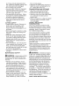
DOUBLE INSULATION
CUTTING
SAFETY
• Inspect
areatobecut.Remove
ob- CONSTRUCTION
This unit is double insulated to help
jects(rocks,
broken
glass,
nails,
protect against electric shock. Double
wire,string,
etc.)which
canbe
thrown
orbecome
entangled
incut- insulation construction consists of two
separate "layers" of electrical insulatinghead.
• Donotoverreach
orstand
onunsta- tion instead of grounding.
blesupport.
Keep
firmfooting
and
Tools built with this insulation system
balance.
are not intended to be grounded. No
• Keep
thecutting
headbelow
waist grounding means is provided on this
level.
Donotraise
handles
above
unit, nor should a means of grounding
yourwaist.
Cutting
headcancome be added to this unit. As a result, the
dangerously
close
toyourbody.
extension cord used with your unit can
• Keep
away
fromcutting
headand
be plugged into any polarized 120 volt
spinning
line.
electrical outlet.
• Useunitproperly.
Useonlyfortrim- Safety precautions must be observed
ming,
scalping,
andmowing.
Donot when operating any electrical tool.
forceunit.Itwilldothejobbetter
double insulation system only proandwithlessriskofinjury
attherate The
vides added protection against injury
forwhich
itwasdesigned.
from an internal electrical in• Useonlyindaylight
oringoodartifi- resulting
sulation failure.
ciallight.
MAINTENANCE
SAFETY
,_WARNING:
All electrical repairs
to this unit, including
housing,
switch,
_WARNIN_I:Disconnect
unitfrom motor, etc., must be diagnosed and rethepower
supply
before
performing paired by qualified service personnel.
maintenance,
orwhenchanging
trim- Replacement parts for a double insumerline.
lated appliance must be recommended
by the manufacturer and identical to
• Maintain
unitaccording
torecom- the
they replace. A double insumended
procedures.
Keep
cutting latedparts
is marked with the
lineatproper
length.
Follow
instruc- words appliance
"double insulation" or "double
tionsforchanging
trimmer
line.
• Have
allservice
andmaintenance insulated". The symbol (square within
a square) [] may also be marked on
notexplained
inthismanual
perappliance.
Failure to have the unit
formed
byaSears
Service
Center
to the
repaired by Sears service personnel
avoid
creating
ahazard.
can cause the double insulation
• Never
douse
orsquirt
theunitwith
to become ineffective and
water
oranyother
liquid.Clean
unit construction
result in serious injury.
andlabels
withadamp
sponge.
SAVE THESE INSTRUCTIONS
Keep
handles
dry,clean,
andfree
CARTON
CONTENTS
Check
carton
contents
against
thefollowing
list.
Model 358,799201
• Trimmer
• Shield
Examine parts for damage.
damaged parts.
Do not use
NOTE: If you need assistance or find
parts missing or damaged, call
1-800-235-5878.
ASSEMBLY
,_/LWARNING:
If received
as-
sembled, review all assembly steps to
ensure your unit is properly assembled
and all fasteners are secure.
• Extend the tube until it snaps into
place.
ADJUSTING
THE HANDLE
1. Loosen wing nut or knob on handle.
2. Rotate the handle on the tube to an
upright position; place in a comfortable position and retighten wing
nut.
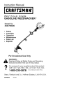
ATTACHING
,_WARNING:
THE SHIELD
The shield must be
properly installed. The shield provides
partial protection from the risk of
thrown objects to the operator and others. Your unit is equipped with a line
limiter blade, which cuts excess line to
the proper length while running. The
line limiter blade (on underside of
shield) is sharp and can cut you.
NOTE: If shield is not properly
installed, damage to unit (including
motor failure) will result.
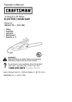
1. Align the installation arrow on the
shield with the installation arrow on
the motor housing (see illustration
below).
2. Insert the shield onto the motor
housing. Ensure cutting line remains free to rotate and is not
caught between the shield and the
motor housing.
3. Twist the shield as illustrated until it
snaps securely into place. Make
sure the shield is facing the back of
the unit as shown on the front cover of this manual.
ALIGN
INSTALLATION
ARROWS
Twist shield in
direction of
arrow to assemble
CAUTION:
Sharp line limiter blade
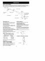
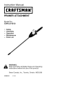
KNOW
YOUR
TRIMMER
READ
THIS
INSTRUCTION
MANUAL
AND
SAFETY
RULES
BEFORE
OPERATING
YOUR
UNIT.
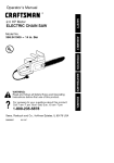
Compare
theillustrations
withyourunittofamiliarize
yourself
withthelocation of
the various controls and adjustments.
Save this manual for future reference.
Trigger Handle
\
_,_ ........ Assist Handle
Motor
/
Recessed
Plug
Housing
Trigger Switch
Semi-automatic
Head with .065"
Trimmer Line
i
Air
Cord Retainer
Vents
/-
J
/-
Tap
Debris Shield ......-" -_"_
RECESSED
PLUG
ASSIST
The RECESSED PLUG is where you attach your extension cord to the unit.
TRIGGER SWITCH
The TRIGGER SWITCH is used to turn
on the unit. Squeeze the trigger switch
to operate the unit.
LINE LIMITER BLADE
The LINE LIMITER BLADE cuts the
cutting line to the proper cutting length.
OPERATING
Button
...... Line Limiter
Blade
HANDLE
The ASSIST HANDLE is used to help
hold and guide the unit.
SEMI-AUTOMATIC
HEAD
The SEMI-AUTOMATIC HEAD holds cutting line and rotates during operation.
TAP BUTTON
The TAP BUTTON is used to advance
the cutting line during operation and to
remove the spool during line replacement.
INSTRUCTIONS
Use only a voltage supply as specified
on your unit.
SELECT AN EXTENSION
Extension
Length
CORD
Cord Gauge Chart
of Cord
25 Ft. (7.5 m)
50 Ft. (15 m)
100 Ft. (30 m)
Gauge
CORRECT
OPERATING
18 Gauge
16 Gauge
16 Gauge
Extension cords are available
unit at Sears.
ATTACH THE EXTENSION
CORD TO YOUR TRIMMER
for this
Loop your extension cord through the
handle and around the hook as
shown. Ensure the plug and cord are
firmly and fully engaged.
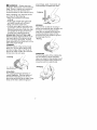
Trimming
POSITION
_WARNING:
Always wear eye
protection. Never lean over the trimmer
head. Rocks or debris can ricochet or
be thrown into eyes and face and
cause blindness or other serious injury.
around trees, posts, monuments, etc.
This technique increases line wear.
Scalping
When operating unit, stand as shown
and check for the following:
• Wear eye protection and heavy
clothing.
• Hold trigger handle with right hand
and assist handle with left hand.
• Keep unit below waist level.
• Cut from your right to your left to ensure debris is thrown away from you.
Without bending over, keep line near
and parallel to the ground and not
crowded into material being cut.
ADVANCING THE CUTTING LINE
Advance line by tapping bottom of cutting head lightly on the ground while
unit is running at full speed. A metal
blade attached to the shield will cut the
line to the proper length.
TRIMMING
Hold the bottom of the trimmer head
about 3 in. (8 cm) above the ground
and at an angle. Allow only the tip of
the line to make contact. Do not force
trimmer line into work area.
Trimming
/
3 in. (8 cm)
Above Ground
SCALPING
The scalping technique removes unwanted vegetation. Hold the bottom of
the trimmer head about 3 in. (8 cm)
above the ground and at an angle. Allow
the tip of the line to strike the ground
MOWING
Your trimmer is ideal for mowing in
places conventional
lawn mowers cannot reach. In the mowing position,
keep the line parallel to the ground.
Avoid pressing the head into the
ground as this can scalp the ground
and damage the tool.
Mowing
/
/
SWEEPING
The fanning action of the rotating line
can be used for a quick and easy
clean up. Keep the line parallel to and
above the surfaces being swept and
move the tool from side to side.
Sweeping
CUSTOMER
RESPONSIBILITIES
WARNING:
Disconnect
power source before performing
CARE & MAINTENANCE
TASK
Check for loose fasteners
and parts
Check for damaged
WHEN TO PERFORM
Before each use
or worn parts
Before each use
Inspect and clean unit and labels
GENERAL
RECOMMENDATIONS
The warranty on this unit does not cover items that have been subjected to
operator abuse or negligence. To receive full value from the warranty, the
operator must maintain unit as instructed in this manual. Various adjustments
will need to be made periodically to
properly maintain your unit.
BEFORE
EACH USE
CHECK FOR LOOSE
FASTENERS AND PARTS
• Housing Screws
• Assist Handle Screws
• Debris Shield
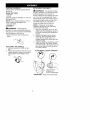
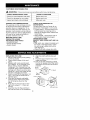
REPLACING THE LINE
1. Remove the spool by firmly pulling
on the tap button.
2. Clean entire surface of hub and
spool.
3. Replace with a pre-wound spool
(#71-85837), or cut a length of 30
feet of .065" (1.6 mm) diameter
Craftsman® Pro Trimmer line. Use
of heavier lines could overload and
damage unit. Never use wire, rope,
string, etc., which can break off and
become a dangerous missile.
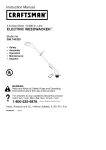
4. Insert one end ofthe line about 1/2
inch (1 cm) into the small hole inside the spool.
5. Wind the line evenly and tightly
onto the spool. Wind in the direction of the arrow found on the
spool.
6. Push the line into the notch, leaving 3 to 5 inches (7 - 12 cm) unwound.
7. Insert the line into the exit hole in
the hub as shown in the illustration.
maintenance.
After each use
CHECK FOR DAMAGED OR
WORN PARTS
Contact Sears Service Center for replacement of damaged or worn parts.
• Trigger Switch - Ensure switch functions properly by pressing and releasing the trigger switch. Make sure
motor stops.
• Debris Shield - Discontinue use of
unit if debris shield is damaged.
AFTER
EACH USE
INSPECT AND CLEAN UNIT AND LABELS
• After each use, inspect complete unit
for loose or damaged parts. Clean
the unit using a damp cloth with a
mild detergent.
• Wipe off unit with a clean dry cloth.
8.
Align the notch with the line exit
hole.
9. Push the spool into the hub until it
snaps into place.
10. Pull on the line extending outside
the hub to release it from the notch;
otherwise, the unit will not function
properly.
Small
Hole_
//7//_2*Z_'_
/
-"_<i I/'ISA_,'\'I
"_--
I ,Lt\tt 7{ spool
Button
Line in Notch
Hub
Line exit hole
USER
REPLACEABLE
SERVICE
PARTS
REPLACEMENT
PART
PART NUMBER
71-85837
Spool
with.065"
ProTrimmer
Line
Assist
Handle
530401991
530401989
BoltCarriage,
1/4-20
530016152
WingNut
530402673
Shield
Assembly
• Store unit and extension cord indoors
_WARNIN_I:
Perform the follow-
ing steps after each use:
• Stop the unit and disconnect the
power source when not in use.
• Carry the unit with motor stopped.
• Store the unit so the line limiter blade
in a high, dry place out of reach of
children. Store unit unplugged.
• Store unit with all guards in place.
Position unit so that any sharp object
cannot accidentally cause injury.
cannot cause injury.
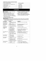
TROUBLESHOOTING
TABLE
,_/LWARNING:
Always stop unit and disconnect from the power source before
performing all of the recommended remedies below except remedies that require unit to be operating.
TROUBLE
Semi-automatic
head stops
under a load or
does not turn
when switch is
pressed.
Line does not
advance or
breaks while
cutting.
CAUSE
1. Crowding trimmer line
against material being
cut.
2. Electrical failure.
3. Thrown circuit breaker.
4. Debris stopping head.
REMEDY
1. Allow tip of line to do the cutting.
2. Contact your Sears Service Center.
3. Check Breaker Box.
4. Remove debris.
1. Line improperly routed
in head.
2. Line improperly
wound onto spool.
3. Incorrect line size
4. Not enough line
outside of head.
5. Dirt buildup on unit.
1. Line size is incorrect.
2. Incorrect spool.
3. Line is being crowded
against material being
cut.
1. Check line routing.
Line releases
continuously.
1. Line improperly
routed in head.
2. Spool damaged.
1. Check line routing.
Line usage is
excessive.
1. Line improperly routed
in head.
2. Line size is incorrect.
3. Crowding line against
material being cut.
4. Spool worn or damaged.
2. Replace spool.
3. Cut with tip of line fully extended.
1. Too little line outside
of head.
2. Line size incorrect.
1. Remove cover and pull 4 in.
(10 cm) of line outside of head.
2. Use only .065 in. (1.65 mm) dia. line.
Line welds onto
spool.
Line pulls back
into head.
2. Rewind line tightly
5.
and evenly.
Use only .065 in. (1.65mm) dia. line.
Remove cover and pull 4 in.
(10 cm) of line out of head.
Clean unit.
1. Use only .065 in. (1.65mm) dia. line.
2. Replace with correct spool,
3. Cut with tip of line fully extended.
2. Replace
spool.
1. Check line routing.
4. Replace
spool.