1
mobile
MC35i
MC35i Terminal
Siemens Cellular Engine
Version:
DocId:
01.03
MC35i_ATC_V01.03
MC35i AT Command Set
s
mobile
Document Name:
MC35i AT Command Set
Version:
01.03
Date:
May 7, 2004
DocId:
MC35i_ATC_V01.03
Status
Confidential / Released
General Notes
Product is deemed accepted by recipient and is provided without interface to recipient’s products. The documentation and/or product are provided for testing, evaluation, integration and information purposes. The documentation and/or product are provided on an “as is” basis only and may contain deficiencies or inadequacies. The
documentation and/or product are provided without warranty of any kind, express or implied. To the maximum
extent permitted by applicable law, Siemens further disclaims all warranties, including without limitation any implied warranties of merchantability, completeness, fitness for a particular purpose and non-infringement of thirdparty rights. The entire risk arising out of the use or performance of the product and documentation remains with
recipient. This product is not intended for use in life support appliances, devices or systems where a malfunction
of the product can reasonably be expected to result in personal injury. Applications incorporating the described
product must be designed to be in accordance with the technical specifications provided in these guidelines. Failure to comply with any of the required procedures can result in malfunctions or serious discrepancies in results.
Furthermore, all safety instructions regarding the use of mobile technical systems, including GSM products,
which also apply to cellular phones must be followed. Siemens or its suppliers shall, regardless of any legal theory upon which the claim is based, not be liable for any consequential, incidental, direct, indirect, punitive or other
damages whatsoever (including, without limitation, damages for loss of business profits, business interruption,
loss of business information or data, or other pecuniary loss) arising out the use of or inability to use the documentation and/or product, even if Siemens has been advised of the possibility of such damages. The foregoing
limitations of liability shall not apply in case of mandatory liability, e.g. under the German Product Liability Act, in
case of intent, gross negligence, injury of life, body or health, or breach of a condition which goes to the root of
the contract. However, claims for damages arising from a breach of a condition, which goes to the root of the
contract, shall be limited to the foreseeable damage, which is intrinsic to the contract, unless caused by intent or
gross negligence or based on liability for injury of life, body or health. The above provision does not imply a
change on the burden of proof to the detriment of the recipient. Subject to change without notice at any time. The
interpretation of this general note shall be governed and construed according to German law without reference
to any other substantive law.
Copyright
Transmittal, reproduction, dissemination and/or editing of this document as well as utilization of its contents and
communication thereof to others without express authorization are prohibited. Offenders will be held liable for
payment of damages. All rights created by patent grant or registration of a utility model or design patent are reserved.
Copyright © Siemens AG May 7, 2004
MC35i_ATC_V01.03
Confidential / Released
Page 2 of 444
5/7/04
MC35i AT Command Set
s
Contents
mobile
Contents
1.
Introduction............................................................................................................................................ 13
1.1
Scope of the document ................................................................................................................. 13
1.2
Related documents ....................................................................................................................... 14
1.3
Document conventions.................................................................................................................. 15
1.3.1
1.3.2
1.4
AT Command Syntax .................................................................................................................... 17
1.4.1
1.4.2
1.5
2.
Software Flow Control (XON/OFF Handshake) ............................................................... 26
Hardware Flow Control (RTS/CTS Handshake)............................................................... 26
Unsolicited Result Code Presentation........................................................................................... 27
1.7.1
1.8
GSM alphabet tables and UCS2 character values........................................................... 21
UCS2 and GSM data coding and conversion for SMS text mode.................................... 23
Implementing output of SIM data to the Terminal (direction TA to TE) ............................. 23
Implementing input of Terminal data to SIM (direction TE to TA) ..................................... 24
Serial Interface Flow Control ......................................................................................................... 26
1.6.1
1.6.2
1.7
Using parameters ............................................................................................................. 17
Combining AT commands on the same command line.................................................... 18
Supported character sets .............................................................................................................. 19
1.5.1
1.5.2
1.5.2.1
1.5.2.2
1.6
Quick reference table ....................................................................................................... 15
Superscript notation for parameters and values............................................................... 16
Communication between Customer Application and MC35i ............................................ 27
Errors and Messages .................................................................................................................... 28
Configuration Commands..................................................................................................................... 29
2.1
AT&F Set all current parameters to manufacturer defaults ......................................................... 29
2.2
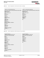
AT&V Display current configuration ............................................................................................ 30
2.2.1
AT&V responses .............................................................................................................. 30
2.3
AT&W Stores current configuration to user defined profile ......................................................... 32
2.4
ATQ Set result code presentation mode ..................................................................................... 33
2.5
ATV Set result code format mode ............................................................................................... 34
2.5.1
Verbose and numeric result codes................................................................................... 34
2.6
ATX Set CONNECT result code format and call monitoring ....................................................... 36
2.7
ATZ Set all current parameters to user defined profile................................................................ 37
2.8
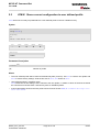
AT+CFUN Set phone functionality .............................................................................................. 38
2.8.1
2.9
Wake up the ME from SLEEP mode ................................................................................ 42
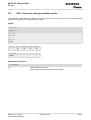
AT^SMSO Switch off mobile station............................................................................................ 43
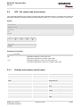
2.10 AT+GCAP Request complete TA capabilities list........................................................................ 44
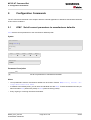
2.11 AT+CMEE Mobile Equipment Error Message Format ................................................................ 45
2.11.1 CME ERRORS related to GSM 07.07.............................................................................. 46
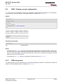
2.11.2 GPRS-related CME ERRORS.......................................................................................... 47
2.11.3 CMS ERRORS related to GSM 07.05.............................................................................. 48
MC35i_ATC_V01.03
Confidential / Released
Page 3 of 444
5/7/04
MC35i AT Command Set
s
Contents
mobile
2.12 AT+CSCS Select TE character set ............................................................................................. 51
2.13 AT^SM20 Set M20 compatibility mode ....................................................................................... 53
3.
Status Control Commands ................................................................................................................... 55
3.1
AT+CMER Mobile Equipment Event Reporting .......................................................................... 55
3.2
AT+CIND Indicator control .......................................................................................................... 58
3.3
AT^SIND Extended Indicator Control .......................................................................................... 62
3.4
AT+CEER Extended Error Report............................................................................................... 65
3.4.1
3.4.2
3.4.3
3.4.4
3.4.5
3.4.6
3.4.7
3.4.8
3.4.9
3.4.10
3.4.11
3.4.12
3.4.13
3.4.14
4.
3.5
ATS18 Extended call release report............................................................................................ 77
3.6
AT+CPAS Mobile equipment activity status ................................................................................ 79
3.7
AT+WS46 Select wireless network ............................................................................................. 80
Serial Interface Control Commands..................................................................................................... 81
4.1
AT\Q Flow control........................................................................................................................ 81
4.2
AT&C Set circuit Data Carrier Detect (DCD) function mode ....................................................... 82
4.3
AT&D Set circuit Data Terminal Ready (DTR) function mode..................................................... 83
4.4
AT&S Set circuit Data Set Ready (DSR) function mode ............................................................. 84
4.5
ATE Enable command echo........................................................................................................ 85
4.6
AT+ILRR Set TE-TA local rate reporting ..................................................................................... 86
4.7
AT+IPR Set fixed local rate ......................................................................................................... 88
4.7.1
4.8
Autobauding ..................................................................................................................... 90
AT+CMUX Enter multiplex mode ................................................................................................ 91
4.8.1
5.
Cause Location ID for the extended error report.............................................................. 67
GSM release cause for L3 Radio Resource (RR) ............................................................ 68
SIEMENS release cause for L3 Radio Resource (RR) .................................................... 69
GSM release cause for Mobility Management (MM) ........................................................ 69
SIEMENS release cause for L3 Mobility Management (MM) ........................................... 70
GSM release cause for L3 Call Control (CC) ................................................................... 70
SIEMENS release cause for L3 Call Control (CC) ........................................................... 72
SIEMENS release cause for L3 Advice of Charge (AOC)................................................ 73
GSM Release cause for Supplementary Service Call...................................................... 73
SIEMENS release cause for Call-related Supplementary Services (CRSS).................... 74
SIEMENS release cause for Session Management (SM) ................................................ 75
GSM cause for L3 Protocol module or other local cause ................................................ 76
SIEMENS release cause for GPRS API........................................................................... 76
SIEMENS release cause for Embedded Netcore............................................................. 76
Restrictions on Multiplex mode ........................................................................................ 92
Security Commands .............................................................................................................................. 95
5.1
AT+CPIN Enter PIN .................................................................................................................... 95
5.1.1
What to do if PIN or password authentication fails?......................................................... 97
5.2
AT+CPIN2 Enter PIN2 ................................................................................................................ 99
5.3
AT^SPIC Display PIN counter ................................................................................................... 102
5.4
AT+CLCK Facility lock .............................................................................................................. 107
5.5
AT^SLCK Facility lock ............................................................................................................... 113
MC35i_ATC_V01.03
Confidential / Released
Page 4 of 444
5/7/04
MC35i AT Command Set
s
Contents
6.
mobile
5.6
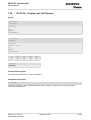
AT+CPWD Change Password .................................................................................................. 114
5.7
AT^SPWD Change Password ................................................................................................... 118
Identification Commands.................................................................................................................... 119
6.1
ATI Display product identification information ........................................................................... 119
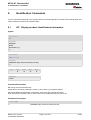
6.2
AT+CGMI Request manufacturer identification......................................................................... 120
6.3
AT+GMI Request manufacturer identification ........................................................................... 121
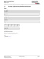
6.4
AT+CGMM Request model identification .................................................................................. 122
6.5
AT+GMM Request TA model identification ............................................................................... 123
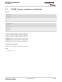
6.6
AT+CGMR Request revision identification of software status................................................... 124
6.7
AT+GMR Request TA revision identification of software status................................................ 125
6.8
AT+CGSN Request product serial number identification (IMEI) identical to GSN .................... 126
6.9
AT+GSN Request TA serial number identification (IMEI) ......................................................... 127
6.10 AT+CIMI Request international mobile subscriber identity ....................................................... 128
7.
Call related Commands....................................................................................................................... 129
7.1
ATA Answer a call ..................................................................................................................... 129
7.2
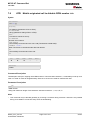
ATD Mobile originated call to dial a number.............................................................................. 131
7.3
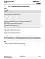
ATD><mem><n> Originate call to phone number in memory................................................... 134
7.4
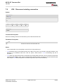
ATD><n> Originate call to phone number selected from active memory.................................. 136
7.5
ATD><str> Originate call to phone number in memory with corresponding field ...................... 138
7.6
ATDI Mobile originated call to dialable ISDN number <n> ........................................................ 140
7.7
ATDL Redial last telephone number used................................................................................. 141
7.8
ATH Disconnect existing connection......................................................................................... 142
7.9
AT+CHUP Hang up call ............................................................................................................ 143
7.10 ATS0 Set number of rings before automatically answering a call ............................................. 144
7.11 ATS6 Set pause before blind dialing ......................................................................................... 145
7.12 ATS7 Set number of seconds to wait for connection completion .............................................. 146
7.13 ATS8 Set number of seconds to wait for comma dialing modifier............................................. 147
7.14 ATS10 Set disconnect delay after indicating the absence of data carrier ................................. 148
7.15 ATP Select pulse dialing ........................................................................................................... 149
7.16 ATO Switch from command mode to data mode / PPP online mode........................................ 150
7.17 +++ Switch from data mode to command mode ....................................................................... 151
7.18 ATT Select tone dialing ............................................................................................................. 152
7.19 AT+CBST Select bearer service type ....................................................................................... 153
7.20 AT+CRLP Select radio link protocol parameters for originated non-transparent data calls ...... 155
7.21 AT+CLCC List current calls of ME ............................................................................................ 157
7.22 AT+CR Service reporting control .............................................................................................. 160
7.23 AT+CRC Set Cellular Result Codes for incoming call indication .............................................. 162
7.24 AT+CSNS Single Numbering Scheme ...................................................................................... 164
7.25 AT^SCNI List Call Number Information ..................................................................................... 166
7.26 AT^SLCD Display Last Call Duration ........................................................................................ 168
MC35i_ATC_V01.03
Confidential / Released
Page 5 of 444
5/7/04
MC35i AT Command Set
s
Contents
mobile
7.27 AT^STCD Display Total Call Duration....................................................................................... 169
8.
Network Service Commands .............................................................................................................. 170
8.1
AT+COPN Read operator names ............................................................................................. 170
8.2
AT+COPS Operator selection ................................................................................................... 172
8.3
AT+CREG Network registration ................................................................................................ 175
8.4
AT+CSQ Signal quality ............................................................................................................. 178
8.5
AT^SMONC Cell Monitoring...................................................................................................... 180
8.6
AT^MONI Monitor idle mode and dedicated mode ................................................................... 182
8.6.1
8.6.2
8.6.3
8.7
AT^MONP Monitor neighbour cells ........................................................................................... 186
8.7.1
8.8
AT^MONP responses..................................................................................................... 187
AT^SMONG GPRS Monitor ...................................................................................................... 188
8.8.1
8.9
AT^MONI responses ...................................................................................................... 183
Service states................................................................................................................. 184
Notes .............................................................................................................................. 184
AT^SMONG Cell Info Table ........................................................................................... 189
AT^SHOM Display Homezone .................................................................................................. 190
8.10 AT^SPLM Read the PLMN list .................................................................................................. 191
8.11 AT^SPLR Read entry from the preferred operators list............................................................. 192
8.12 AT^SPLW Write an entry to the preferred operators list ........................................................... 194
9.
Supplementary Service Commands .................................................................................................. 195
9.1
AT+CACM Accumulated call meter (ACM) reset or query ........................................................ 195
9.2
AT^SACM Advice of charge and query of ACM and ACMmax ................................................. 197
9.3
AT+CAMM Accumulated call meter maximum (ACMmax) set or query.................................... 199
9.4
AT+CAOC Advice of Charge information.................................................................................. 201
9.5
AT+CCUG Closed User Group ................................................................................................. 203
9.6
AT+CCFC Call forwarding number and conditions control ....................................................... 205
9.7
AT+CCWA Call Waiting ............................................................................................................ 209
9.8
AT+CHLD Call Hold and Multiparty........................................................................................... 213
9.9
AT+CLIP Calling line identification presentation ....................................................................... 216
9.10 AT+CLIR Calling line identification restriction ........................................................................... 218
9.11 AT+CPUC Price per unit and currency table............................................................................. 220
9.12 AT+CSSN Supplementary service notifications ........................................................................ 222
9.13 AT+CUSD Supplementary service notifications ........................................................................ 224
10.
GPRS Commands ................................................................................................................................ 226
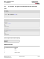
10.1 AT+CGACT PDP context activate or deactivate ....................................................................... 226
10.2 AT+CGATT GPRS attach or detach ......................................................................................... 228
10.3 AT+CGDATA Enter data state .................................................................................................. 230
10.4 AT+CGDCONT Define PDP Context ........................................................................................ 232
10.5 AT+CGPADDR Show PDP address ......................................................................................... 234
10.6 AT+CGQMIN Quality of Service Profile (Minimum acceptable) ................................................ 235
MC35i_ATC_V01.03
Confidential / Released
Page 6 of 444
5/7/04
MC35i AT Command Set
s
Contents
mobile
10.7 AT+CGQREQ Quality of Service Profile (Requested) .............................................................. 239
10.8 AT+CGREG GPRS network registration status ........................................................................ 243
10.9 AT+CGSMS Select service for MO SMS messages ................................................................. 245
10.10 AT^SGACT Query all PDP context activations ......................................................................... 247
10.11 AT^SGAUTH Set type of authentication for PPP connection.................................................... 249
10.12 AT^SGCONF Configuration of GPRS related Parameters ...................................................... 250
10.13 ATD*99# Request GPRS service.............................................................................................. 252
10.14 ATD*98# Request GPRS IP service ......................................................................................... 254
10.15 ATH Manual rejection of a network request for PDP context activation.................................... 255
10.16 Using GPRS AT commands (Examples)..................................................................................... 256
10.17 Using the GPRS dial command ATD .......................................................................................... 258
11.
FAX Commands ................................................................................................................................... 259
11.1 FAX parameters .......................................................................................................................... 259
11.2 AT+FBADLIN Bad Line Threshold ............................................................................................ 262
11.3 AT+FBADMUL Error Threshold Multiplier ................................................................................. 263
11.4 AT+FBOR Query data bit order................................................................................................. 264
11.5 AT+FCIG Query or set the Local Polling ID .............................................................................. 265
11.6 AT+FCLASS Fax: Select, read or test service class ................................................................. 266
11.7 AT+FCQ Copy Quality Checking .............................................................................................. 268
11.8 AT+FCR Capability to receive ................................................................................................... 269
11.9 AT+FDCC Query or set capabilities .......................................................................................... 270
11.10 AT+FDFFC Data Compression Format Conversion ................................................................. 271
11.11 AT+FDIS Query or set session parameters .............................................................................. 272
11.12 AT+FDR Begin or continue phase C data reception ................................................................. 273
11.13 AT+FDT Data Transmission...................................................................................................... 274
11.14 AT+FET End a page or document ............................................................................................ 275
11.15 AT+FK Kill operation, orderly FAX abort ................................................................................... 276
11.16 AT+FLID Query or set the Local Id setting capabilities ............................................................. 277
11.17 AT+FMDL Identify Product Model ............................................................................................ 278
11.18 AT+FMFR Request Manufacturer Identification ........................................................................ 279
11.19 AT+FOPT Set bit order independently ...................................................................................... 280
11.20 AT+FPHCTO DTE Phase C Response Timeout....................................................................... 281
11.21 AT+FREV Identify Product Revision ......................................................................................... 282
11.22 AT+FRH Receive Data Using HDLC Framing .......................................................................... 283
11.23 AT+FRM Receive Data ............................................................................................................. 284
11.24 AT+FRS Receive Silence.......................................................................................................... 285
11.25 AT+FTH Transmit Data Using HDLC Framing .......................................................................... 286
11.26 AT+FTM Transmit Data............................................................................................................. 287
11.27 AT+FTS Stop Transmission and Wait....................................................................................... 288
11.28 AT+FVRFC Vertical resolution format conversion .................................................................... 289
MC35i_ATC_V01.03
Confidential / Released
Page 7 of 444
5/7/04
MC35i AT Command Set
s
Contents
12.
mobile
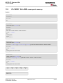
Short Message Service (SMS) Commands........................................................................................ 290
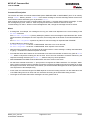
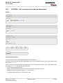
12.1 SMS parameters ......................................................................................................................... 290
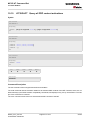
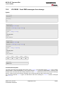
12.2 AT+CMGC Send an SMS command......................................................................................... 294
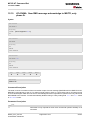
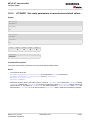
12.3 AT+CMGD Delete SMS message............................................................................................. 295
12.4 AT+CMGF Select SMS message format .................................................................................. 296
12.5 AT+CMGL List SMS messages from preferred store................................................................ 297
12.6 AT+CMGR Read SMS messages............................................................................................. 299
12.7 AT+CMGS Send SMS message ............................................................................................... 301
12.8 AT+CMGW Write SMS messages to memory .......................................................................... 303
12.9 AT+CMSS Send SMS messages from storage ........................................................................ 305
12.10 AT+CNMA New SMS message acknowledge to ME/TE, only phase 2+ .................................. 306
12.11 AT+CNMI New SMS message indications ................................................................................ 308
12.12 AT+CPMS Preferred SMS message storage ............................................................................ 312
12.13 AT+CSCA SMS service centre address.................................................................................... 314
12.14 AT+CSCB Select Cell Broadcast Message Indication .............................................................. 315
12.15 AT+CSDH Show SMS text mode parameters........................................................................... 317
12.16 AT+CSMP Set SMS text mode parameters .............................................................................. 318
12.17 AT+CSMS Select Message Service.......................................................................................... 320
12.18 AT^SLMS List SMS Memory Storage ....................................................................................... 322
12.19 AT^SMGL List SMS messages from preferred store without setting status to REC READ ...... 324
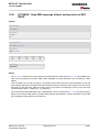
12.20 AT^SMGO Set or query SMS overflow presentation mode or query SMS overflow ................. 326
12.21 AT^SMGR Read SMS message without setting status to REC READ ..................................... 328
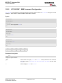
12.22 AT^SSCONF SMS Command Configuration ........................................................................... 329
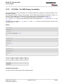
12.23 AT^SSDA Set SMS Display Availability .................................................................................... 330
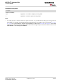
12.24 AT^SSMSS Set Short Message Storage Sequence ................................................................. 332
13.
SIM related Commands ....................................................................................................................... 333
13.1 AT+CRSM Restricted SIM Access ............................................................................................ 333
13.2 AT^SCKS Query SIM and Chip Card Holder Status ................................................................. 336
13.3 AT^SSET Indicate SIM data ready............................................................................................ 338
13.4 AT^SCID Display SIM card identification number ..................................................................... 340
13.5 AT+CXXCID Display card ID..................................................................................................... 341
14.
SIM Application Toolkit (SAT) Commands........................................................................................ 342
14.1 AT^SSTA SAT Interface Activation ........................................................................................... 342
14.2 ^SSTN SAT Notification ............................................................................................................ 344
14.3 AT^SSTGI SAT Get Information ............................................................................................... 346
14.4 AT^SSTR SAT Response ......................................................................................................... 348
15.
Phonebook Commands....................................................................................................................... 350
15.1 Sort Order for Phonebooks ......................................................................................................... 350
15.2 AT+CPBR Read from Phonebook............................................................................................. 351
15.3 AT+CPBS Select phonebook memory storage ......................................................................... 354
MC35i_ATC_V01.03
Confidential / Released
Page 8 of 444
5/7/04
MC35i AT Command Set
s
Contents
mobile
15.4 AT+CPBW Write into Phonebook ............................................................................................. 356
15.5 AT^SPBC Search the first entry in the sorted telephone book.................................................. 359
15.6 AT^SPBD Purge phonebook memory storage.......................................................................... 361
15.7 AT^SPBG Read current Phonebook entries ............................................................................. 363
15.8 AT^SPBS Step through the selected phonebook alphabetically ............................................... 367
15.9 AT^SDLD Delete the 'last number redial' memory .................................................................... 371
16.
Audio Commands ................................................................................................................................ 372
16.1 Audio programming model .......................................................................................................... 372
16.2 ATL Set monitor speaker loudness ........................................................................................... 373
16.3 ATM Set monitor speaker mode................................................................................................ 374
16.4 AT+CLVL Loudspeaker volume level........................................................................................ 375
16.5 AT+CMUT Mute control ............................................................................................................ 377
16.6 AT+VTD Tone duration ............................................................................................................. 378
16.7 AT+VTS DTMF and tone generation......................................................................................... 379
16.8 AT^SAIC Audio Interface Configuration .................................................................................... 381
16.9 AT^SNFA Set or query of microphone attenuation .................................................................. 383
16.10 AT^SNFD Set audio parameters to manufacturer default values ............................................. 385
16.11 AT^SNFI Set microphone path parameters .............................................................................. 386
16.12 AT^SNFM Mute microphone ..................................................................................................... 388
16.13 AT^SNFO Set audio output (= loudspeaker path) parameter ................................................... 390
16.14 AT^SNFPT Set progress tones ................................................................................................. 392
16.15 AT^SNFS Select audio hardware set........................................................................................ 393
16.16 AT^SNFV Set loudspeaker volume ........................................................................................... 397
16.17 AT^SNFW Write audio setting in non-volatile store .................................................................. 399
16.18 AT^SRTC Ring tone configuration ............................................................................................ 400
17.
Hardware related Commands ............................................................................................................. 403
17.1 AT+CALA Set alarm time ......................................................................................................... 403
17.1.1 Summary of AT commands available in Alarm mode .................................................... 406
17.2 AT+CCLK Real Time Clock....................................................................................................... 407
17.3 AT^SBC Battery charge and charger control ............................................................................ 408
17.4 AT^SCTM Set critical operating temperature presentation mode or query temperature........... 410
17.4.1 Deferred shutdown ......................................................................................................... 413
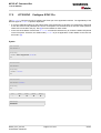
17.5 AT^SSYNC Configure SYNC Pin.............................................................................................. 414
17.5.1 ME status indicated by status LED patterns................................................................... 415
18.
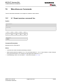
Miscellaneous Commands.................................................................................................................. 416
18.1 A/ Repeat previous command line ............................................................................................ 416
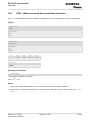
18.2 ATS3 Write command line termination character...................................................................... 417
18.3 ATS4 Set response formatting character .................................................................................. 418
18.4 ATS5 Write command line editing character ............................................................................. 419
MC35i_ATC_V01.03
Confidential / Released
Page 9 of 444
5/7/04
MC35i AT Command Set
s
Contents
19.
mobile
Appendix .............................................................................................................................................. 420
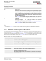
19.1 Restricted access to SIM data after SIM PIN authentication....................................................... 420
19.2 List of Star-Hash (*#) Codes ....................................................................................................... 421
19.3 Available AT Commands and Dependency on SIM PIN ............................................................. 424
19.4 AT Command Settings storable with AT&W................................................................................ 431
19.5 Factory Default Settings Restorable with AT&F .......................................................................... 434
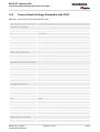
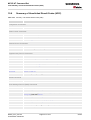
19.6 Summary of Unsolicited Result Codes (URC)............................................................................. 437
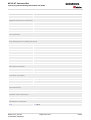
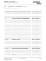
19.7 Alphabetical List of AT Commands ............................................................................................. 439
MC35i_ATC_V01.03
Confidential / Released
Page 10 of 444
5/7/04
MC35i AT Command Set
s
List of Tables
mobile
List of Tables
Table 1.1:
Table 1.2:
Table 1.3:
Table 1.4:
Table 2.1:
Table 2.2:
Table 2.3:
Table 4.1:
Table 4.2:
Table 17.1:
Table 17.2:
Table 19.1:
Table 19.2:
Table 19.3:
Table 19.4:
Table 19.5:
Table 19.6:
Table 19.7:
Table 19.8:
Table 19.9:
Table 19.10:
Product specific use of AT commands ...................................................................................... 13
Symbols used to mark the type of parameters ........................................................................... 16
Symbols used to indicate the correlations with other commands ............................................... 16
Symbols used to mark different types of default values of parameters ..................................... 16
Current configuration on ASC0 / MUX channel 1 (example) ...................................................... 31
Current configuration on MUX channels 2 and 3 (example) ...................................................... 31
Wake-up events in NON-CYCLIC and CYCLIC SLEEP modes ................................................. 42
Availability of AT Commands on Virtual Channels .................................................................... 92
Summary of AT commands with Different Behavior in Multiplex Mode ..................................... 93
List of AT commands available in Alarm mode ........................................................................ 406
Modes of the LED and indicated ME functions......................................................................... 415
List of Star-Hash (*#) Codes .................................................................................................... 421
Abbreviations of Codes and Parameters used in Table 19.1, List of Star-Hash (*#) Codes ... 422
Possible Star-Hash Command Responses ............................................................................. 423
Star-Hash Codes for Supplementary Services ........................................................................ 423
Available AT Commands and Dependency on SIM PIN........................................................... 424
Settings Stored to User Profile on ASC0 / MUX Channel 1...................................................... 431
Settings Stored to User Profile on MUX Channels 2 and 3 ...................................................... 432
Factory Default Settings Restorable with AT&F ....................................................................... 434
Summary of Unsolicited Result Codes (URC) .......................................................................... 437
Alphabetical List of AT Commands........................................................................................... 439
MC35i_ATC_V01.03
Confidential / Released
Page 11 of 444
5/7/04
MC35i AT Command Set
s
List of Figures
mobile
List of Figures
Figure 1.1:
Figure 1.2:
Figure 16.1:
Main character table of GSM 03.38 alphabet ............................................................................. 21
Extension character table of GSM 03.38 alphabet ..................................................................... 22
Audio programming model........................................................................................................ 372
MC35i_ATC_V01.03
Confidential / Released
Page 12 of 444
5/7/04
MC35i AT Command Set
s
1. Introduction
mobile
1.
Introduction
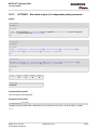
1.1
Scope of the document
This document presents the AT Command Set for the Siemens Cellular Engines
MC35i Version 01.03
MC35i Terminal Version 01.03.
Before using the Cellular Engine or upgrading to a new firmware version please read the latest product information provided in the Release Notes [1].
More information is available at the Siemens Website: http://www.siemens.com/wm.
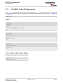
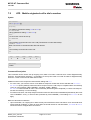
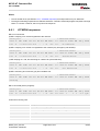
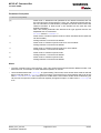
If features differ between MC35i and MC35i Terminal this is noted in the section that refers to the AT command.
At present the following features are concerned:
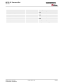
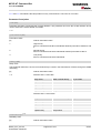
Table 1.1:
Product specific use of AT commands
AT command
Module version
Terminal version
AT+ILRR
Maximum bit rate: 230400 bps
Maximum bit rate: 115200 bps
AT+IPR
Maximum bit rate: 230400 bps
Maximum bit rate: 115200 bps
AT+CALA
Alarm mode and reminder message fully Does not support Alarm mode. Please
applicable
ignore any information relating to the
subject.
The reminder message can be used as
described.
AT^SAIC
All parameters usable as described.
Additional recommendations for using
audio modes 2, 3 and 6 with MC35i Terminal.
AT^SSYNC
SYNC pin may be assigned different
functions: <mode> 0 or 1.
SYNC pin supports only <mode>=1 .
(LED status)
AT^SBC
All functions fully applicable
Command not applicable
MC35i_ATC_V01.03
Confidential / Released
Page 13 of 444
5/7/04
MC35i AT Command Set
s
1.2 Related documents
1.2
mobile
Related documents
[1] MC35i Release Notes, Version 01.03
[2] MC35i Hardware Interface Description, Version 01.03
[3] MC35i Terminal Hardware Interface Description
[4] GPRS Startup User's Guide
[5] Remote-SAT User's Guide
[6] Multiplexer User's Guide
[7] Multiplex Driver Developer's Guide for Windows 2000 and Windows XP
[8] Multiplex Driver Installation Guide for Windows 2000 and Windows XP
[9] Application Note 02: Audio Interface Design
[10] Application Note 16: Updating MC35i Firmware
[11] Application Note 24: Application Developer's Guide
[12] ISO/IEC10646: "Universal Multiple-Octet Coded Character Set (UCS)"; UCS2, 16 bit coding
[13] ITU-T Recommendation V.24: List of definitions for interchange circuits between data terminal equipment
(DTE) and data circuit-terminating equipment (DCE)
[14] ITU-T Recommendation V.25ter: Serial asynchronous automatic dialling and control
[15] 3GPP TS 100 918/EN 300 918 (GSM 02.04): General on supplementary services
[16] 3GPP TS 100 907 (GSM 02.30): Man-Machine Interface (MMI) of the Mobile Station (MS)
[17] 3GPP TS 23.038 (GSM 03.38): Alphabets and language specific information
[18] 3GPP TS 27.005 (GSM 07.05): Use of Data Terminal Equipment - Data Circuit terminating Equipment (DTE
- DCE) interface for Short Message Service (SMS) and Cell Broadcast Service (CBS)
[19] 3GPP TS 27.007 (GSM 07.07): AT command set for User Equipment (UE)
[20] 3GPP TS 27.060 (GSM 07.60): Mobile Station (MS) supporting Packet Switched Services
[21] 3GPP TS 51.011 (GSM 11.11): Specification of the Subscriber Identity Module - Mobile Equipment (SIM -
ME) interface
[22] 3GPP TS 11.14 (GSM 11.14): Specification of the SIM Application Toolkit for the Subscriber Identity Module
- Mobile Equipment (SIM - ME) interface
MC35i_ATC_V01.03
Confidential / Released
Page 14 of 444
5/7/04
MC35i AT Command Set
s
1.3 Document conventions
1.3
mobile
Document conventions
Throughout the document, the GSM engines are referred to as ME (Mobile Equipment), MS (Mobile Station), TA
(Terminal Adapter), DCE (Data Communication Equipment) or facsimile DCE (FAX modem, FAX board). When
the Siemens product names are required to distinguish the two models, MC35i is short for the engine type and
MC35iT for the terminal.
To control your GSM engine you can simply send AT Commands via its serial interface. The controlling device
at the other end of the serial line is referred to as TE (Terminal Equipment), DTE (Data Terminal Equipment) or
plainly 'the application' (probably running on an embedded system).
All abbreviations and acronyms used throughout this document are based on the GSM specifications. For definitions please refer to TR 100 350 V7.0.0 (1999-08), (GSM 01.04, version 7.0.0 release 1998).
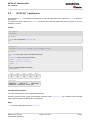
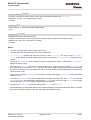
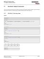
1.3.1
Quick reference table
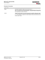
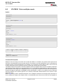
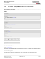
Each AT command description includes a table similar to the example shown below. The table is intended as a
quick reference to indicate the following functions:
PIN:
Is the AT command PIN protected?
%
Yes
!
No
§
Usage is dependent on conditions specified for the command, or not all command types are PIN
protected (for example write command PIN protected, read command not).
Note: The table provided in Section 19.3, Available AT Commands and Dependency on SIM
PIN uses the same symbols.
ASC0:
Is the AT command supported on the physical serial interface ASC0?
%
Yes
!
No
Note: In the case of MC35i only "Yes" applies.
MUXn: Is the AT command usable on the Multiplexer channels MUX1, MUX2, MUX3?
%
Yes
!
No
§
AT command is usable, but under the restrictions specified in the section related to the command.
Note: The columns MUX1, MUX2 and MUX3 are relevant only when the GSM engine operates in Multiplexer mode, that is, when the physical serial interface is partitioned into 3 virtual channels by
using the Multiplexer protocol. Usage is the same on ASC0 and MUX1.
Example:
PIN
ASC0
MUX1
MUX2
MUX3
!
%
§
§
§
MC35i_ATC_V01.03
Confidential / Released
Page 15 of 444
5/7/04
MC35i AT Command Set
s
1.3 Document conventions
mobile
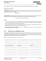
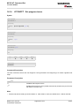
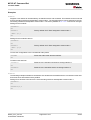
1.3.2
Superscript notation for parameters and values
Table 1.2:
Symbols used to mark the type of parameters
Parameter type
(num)
Meaning
<param>
Parameter value must be numeric type
<param>(str)
Parameter value must be string type
Table 1.3:
Symbols used to indicate the correlations with other commands
Parameter option
(&W)
Meaning
<param>
Parameter value will be stored with AT&W
<param>(&V)
Parameter value will be displayed with AT&V
(ˆSNFW)
<param>
Parameter value will be stored with AT^SNFW
<param>(+CSCS)
Parameter value has to be (is) coded according to current setting of <chset> (see
AT+CSCS for details)
Table 1.4:
Symbols used to mark different types of default values of parameters
Value option
Meaning
[x]
Default value: if the parameter is omitted, the value 'x' will be assumed
x(&F)
Factory default value, will be restored to 'x' with AT&F
x
(P)
x(D)
MC35i_ATC_V01.03
Confidential / Released
Powerup default value of a parameter which is not stored at power down
Delivery default value of a parameter which cannot be restored automatically
Page 16 of 444
5/7/04
MC35i AT Command Set
s
1.4 AT Command Syntax
1.4
mobile
AT Command Syntax
The "AT" or "at" prefix must be set at the beginning of each command line. To terminate a command line enter
<CR>.
Commands are usually followed by a response that includes "<CR><LF><response><CR><LF>". Throughout this
document, only the responses are presented, <CR><LF> are omitted intentionally.
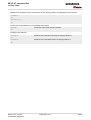
Types of AT commands and responses:
AT command type
Syntax
Function
Test command
AT+CXXX=?
The mobile equipment returns the
list of parameters and value ranges
set with the corresponding Write
command or by internal processes.
Read command
AT+CXXX?
This command returns the currently
set value of the parameter or
parameters.
Write command
AT+CXXX=<...>
This command sets user-definable
parameter values.
Exec(ution) command
AT+CXXX
The execution command reads
non-variable parameters determined by internal processes in the
GSM engine.
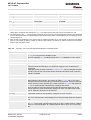
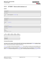
1.4.1
Using parameters
•
Optional parameters are enclosed in square brackets. If optional parameters are omitted, the current settings
are used until you change them.
•
Optional parameters or subparameters can be omitted unless they are followed by other parameters. If you
want to omit a parameter in the middle of a string it must be replaced by a comma. See also example 1.
•
A parameter value enclosed in square brackets represents the value that will be used if an optional parameter
is omitted. See also example 2.
•
When the parameter is a character string, e.g. <text> or <number>, the string must be enclosed in quotation
marks, e.g. "Charlie Brown" or "+49030xxxx". Symbols within quotation marks will be recognized as strings.
•
All spaces will be ignored when using strings without quotaton marks.
•
It is possible to omit the leading zeros of strings which represent numbers.
•
If an optional parameter of a V.25ter command is omitted, its value is assumed to be 0.
MC35i_ATC_V01.03
Confidential / Released
Page 17 of 444
5/7/04
MC35i AT Command Set
s
1.4 AT Command Syntax
mobile
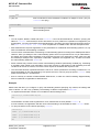
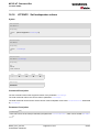
Example 1: Omitting parameters in the middle of a string
Query current setting
AT+CCUG?
+CCUG: 1,10,1
OK
AT+CCUG=,9
Set only the middle parameter
OK
Query new setting
AT+CCUG?
+CCUG: 1,9,1
OK
Example 2: Using default parameter values for optional parameters
AT+CFUN=5,0
Activate CYCLIC SLEEP mode, don't reset ME
OK
Query ME mode
AT+CFUN?
+CFUN: 5
OK
Set ME back to normal (default parameters: 1,0)
AT+CFUN=
OK
+CFUN: 1
OK
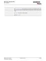
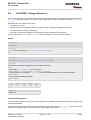
1.4.2
Combining AT commands on the same command line
You may enter several AT commands on the same line. This eliminates the need to type the "AT" or "at" prefix
before each command. Instead, it is only needed once at the beginning of the command line. Use a semicolon
as command delimiter.
The command line buffer accepts a maximum of 391 characters. If this number is exceeded none of the commands will be executed and TA returns ERROR.
The table below lists the AT commands you cannot enter together with other commands on the same line. Otherwise, the responses may not be in the expected order.
AT command type
Comment
V.25ter commands
with FAX commands (Prefix AT+F)
GSM 7.07 commands
with Siemens commands, Prefix AT^S)
GSM 7.05 commands (SMS)
To be used standalone
Commands starting with AT&
To be used standalone
AT+IPR
To be used standalone
Note: When concatenating AT commands please keep in mind that the sequence of processing may be different
from the sequential order of command input. Therefore, if the consecutive order of the issued commands is your
concern, avoid concatenating commands on the same line.
MC35i_ATC_V01.03
Confidential / Released
Page 18 of 444
5/7/04
MC35i AT Command Set
s
1.5 Supported character sets
1.5
mobile
Supported character sets
The ME supports two character sets: GSM 03.38 (7 bit, also referred to as GSM alphabet or SMS alphabet) and
UCS2 (16 bit, refer to ISO/IEC 10646). See AT+CSCS for information about selecting the character set. Character
tables can be found below.
Explanation of terms
•
International Reference Alphabet (IRA)
IRA means that one byte is displayed as two characters in hexadecimal format. For example, the byte 0x36
(decimal 54) is displayed as "36" (two characters). IRA is used here for input 8-bit or 16-bit data via terminal
devices using text mode. This means only characters 'A'..F','a'..'f' and '0'..'9' are valid.
•
Escape sequences
The escape sequence used within a text coded in the GSM default alphabet (0x1B) must be correctly interpreted by the TE, both for character input and output. To the module, an escape sequence appears like any
other byte received or sent.
•
Terminal Adapter (TA)
TA is used equivalent to Mobile Equipment (ME) which stands for the GSM module described here. It uses
GSM default alphabet as its character set.
•
Terminal Equipment (TE)
TE is the device connected to the TA via serial interface. In most cases TE is an ANSI/ASCII terminal that
does not fully support the GSM default alphabet, for example MS Hyperterminal.
•
TE Character Set
The character set currently used by Terminal Equipment is selected with AT+CSCS.
•
Data Coding Scheme (dcs)
DCS is part of a short message and is saved on the SIM. When writing a short message to the SIM in text
mode, the dcs stored with AT+CSMP is used and determines the coded character set.
The behavior when encountering characters, that are not valid characters of the supported alphabets, is undefined.
Due to the constraints described below it is recommended to prefer the USC2 alphabet in any external application.
If the GSM alphabet is selected all characters sent over the serial line (between TE and TA) are in the range from
0 to 127 (7 Bit range). CAUTION: ASCII alphabet (TE) is not GSM alphabet (TA/ME) !
Several problems resulting from the use of GSM alphabet with ASCII terminal equipment:
•
"@" character with GSM alphabet value 0 is not printable by an ASCII terminal program (e.g. Microsoft©
Hyperterminal®).
•
"@" character with GSM alphabet value 0 will terminate any C string! This is because the 0 is defined as C
string end tag. Therefore, the GSM Null character may cause problems on application level when using a 'C'function as "strlen()". This can be avoided if it is represented by an escape sequence as shown in the table
below.
By the way, this may be the reason why even network providers often replace "@"with "@=*" in their SIM
application.
•
Other characters of the GSM alphabet are misinterpreted by an ASCII terminal program. For example, GSM
"ö" (as in "Börse") is assumed to be "|" in ASCII, thus resulting in "B|rse". This is because both alphabets mean
different characters with values hex. 7C or 00 and so on.
•
In addition, decimal 17 and 19 which are used as XON/XOFF control characters when software flow control
is activated, are interpreted as normal characters in the GSM alphabet.
When you write characters differently coded in ASCII and GSM (e.g. Ä, Ö, Ü), you need to enter escape
sequences. Such a character is translated into the corresponding GSM character value and, when output later,
the GSM character value can be presented. Any ASCII terminal then will show wrong responses.
MC35i_ATC_V01.03
Confidential / Released
Page 19 of 444
5/7/04
MC35i AT Command Set
s
1.5 Supported character sets
mobile
Examples for character definitions depending on alphabet
GSM 03.38
character
GSM character
hex. value
Corresponding
ASCII character
ASCII
Esc sequence
Hex Esc
sequence
Ö
5C
\
\5C
5C 35 43
"
22
"
\22
5C 32 32
ò
08
BSP
\08
5C 30 38
@
00
NULL
\00
5C 30 30
CAUTION: Often, the editors of terminal programs do not recognize escape sequences. In this case, an escape
sequence will be handled as normal characters. The most common workaround to this problem is to write a script
which includes a decimal code instead of an escape sequence. This way you can write, for example, short messages which may contain differently coded characters.
MC35i_ATC_V01.03
Confidential / Released
Page 20 of 444
5/7/04
MC35i AT Command Set
s
1.5 Supported character sets
1.5.1
mobile
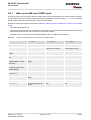
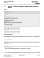
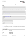
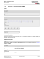
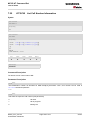
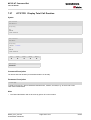
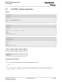
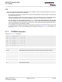
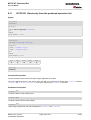
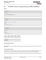
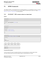
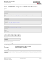
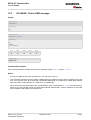
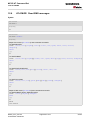
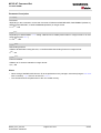
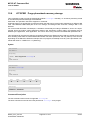
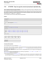
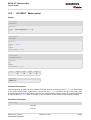
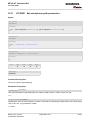
GSM alphabet tables and UCS2 character values
This section provides tables for the GSM 03.38 alphabet supported by the ME. Below any GSM character find
the corresponding two byte character value of the UCS2 alphabet.
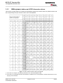
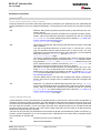
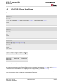
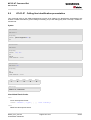
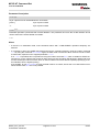
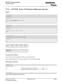
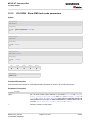
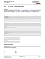
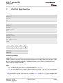
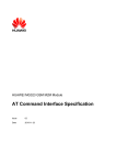
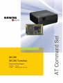
Figure 1.1: Main character table of GSM 03.38 alphabet
1) This code is an escape to the following extension of the 7 bit default alphabet table.
2) This code is not a printable character and therefore not defined for the UCS2 alphabet. It shall be treated as the accompanying control character.
MC35i_ATC_V01.03
Confidential / Released
Page 21 of 444
5/7/04
MC35i AT Command Set
s
1.5 Supported character sets
mobile
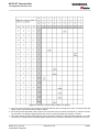
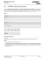
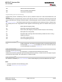
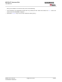
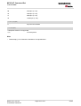
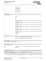
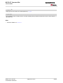
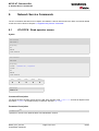
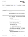
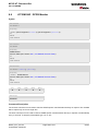
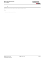
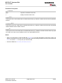
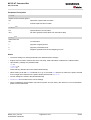
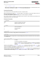
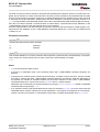
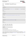
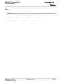
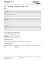
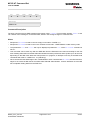
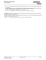
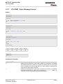
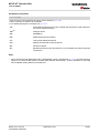
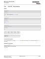
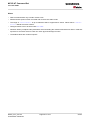
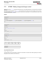
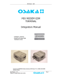
Figure 1.2: Extension character table of GSM 03.38 alphabet
1) This code value is reserved for the extension to another extension table. On receipt of this code, a receiving entity shall
display a space until another extension table is defined.
2) This code represents the EURO currency symbol. The code value is the one used for the character 'e'. Therefore a receiving entity which is incapable of displaying the EURO currency symbol will display the character 'e' instead.
3) This code is defined as a Page Break character and may be used for example in compressed CBS messages. Any mobile
which does not understand the 7 bit default alphabet table extension mechanism will treat this character as Line Feed.
MC35i_ATC_V01.03
Confidential / Released
Page 22 of 444
5/7/04
MC35i AT Command Set
s
1.5 Supported character sets
mobile
In the event that an MS receives a code where a symbol is not represented in Figure 1.2, Extension character
table of GSM 03.38 alphabet the MS shall display the character shown in the main default 7 bit alphabet table
(see Figure 1.1, Main character table of GSM 03.38 alphabet).
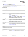
1.5.2
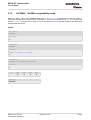
UCS2 and GSM data coding and conversion for SMS text mode
This section provides basic information on how to handle input and output character conversion for SMS text
mode and Remote-SAT if internal (TA) and external (TE) character representation differ, i.e. if the Data Coding
Scheme and the TE character use different coding.
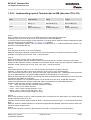
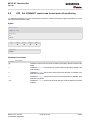
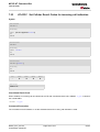
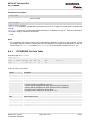
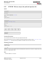
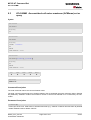
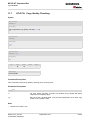
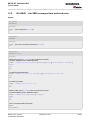
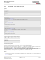
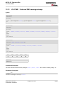
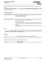
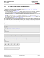
1.5.2.1 Implementing output of SIM data to the Terminal (direction TA to
TE)
dcs
CSCS
7-Bit
(GSM default)
8-Bit
(Data)
16-Bit
(UCS2)
GSM
Case 1
GSM (1:1)
Case 2
8-bit to IRA (1:2)
Case 3
UCS2 to IRA (2:4)
UCS2
Case 4
GSM to IRA (1:4)
Case 5
8-Bit to IRA (1:4)
Case 6
UCS2 to IRA (2:4)
The relation of SIM bytes to output bytes is given in parentheses.
Case 1
Every GSM character is sent to TE as it is (8-bit value with highest bit set to zero).
Example: 47'H, 53'H, 4D'H ® 47'H, 53'H, 4D'H, displayed as "GSM"
Case 2
Every data byte will is sent to TE as 2 IRA characters each representing a halfbyte.
Example: B8'H (184 decimal) ® 42'H, 38'H, displayed as "B8"
Case 3
Every 16-bit UCS2 value is sent to TE as 4 IRA characters.
Example: C4xA7'H (50343 decimal) ® 43'H, 34'H, 41'H, 37'H, displayed as "C4A7"
Problem: An odd number of bytes leads to an error because there are always two bytes needed for each USC2
character
Case 4
Every GSM character is sent to TE as 4 IRA characters to show UCS2 in text mode.
Example: 41'H ("A") ® 30'H, 30'H, 34'H, 31'H, displayed as "0041"
Case 5
Every data byte is sent to TE as IRA representation of UCS2 (similar to case 4).
Example: B2'H ® 30'H, 30'H, 42'H, 32'H, displayed as "00B2"
Case 6
Every 16-bit value is sent to TE as IRA representation of it. It is assumed that number of bytes is even.
Example: C3x46'H ® 43'H, 33'H, 34'H, 36'H, displayed as "C346"
MC35i_ATC_V01.03
Confidential / Released
Page 23 of 444
5/7/04
MC35i AT Command Set
s
1.5 Supported character sets
mobile
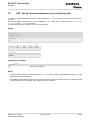
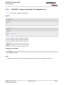
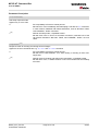
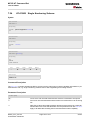
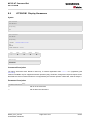
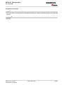
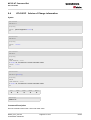
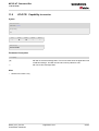
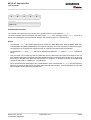
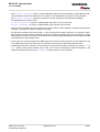
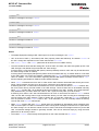
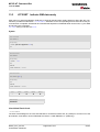
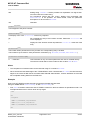
1.5.2.2 Implementing input of Terminal data to SIM (direction TE to TA)
dcs
CSCS
7-Bit
(GSM default)
8-Bit
(Data)
16-Bit
(UCS2)
GSM
Case 1
GSM (1:1)
Case 2
IRA to 8-Bit (2:1)
Case 3
IRA to 16-Bit (4:2)
UCS2
Case 4
UCS2 to GSM (4:1)
Case 5
UCS2 to 8-Bit (4:1)
Case 6
UCS2 to 16-Bit (4:2)
The relation between number of input characters and stored bytes on SIM is given in parentheses.
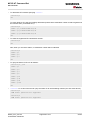
Case 1
Every character is sent from TE to TA as GSM character (or ASCII with Hyperterminal).
Character value must be in range from 0 to 127 because of 7-bit GSM alphabet.
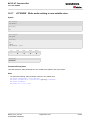
To reach maximum sms text length of 160 characters in 140 bytes space characters will be compressed on SIM.
This must be set using the parameter <dcs> of AT+CSMP (add 64).
Example: "ABCDEFGH" typed is sent and stored uncompressed as ® 4142434445464748'H (stored compressed as 41E19058341E91'H)
Case 2
Every data byte is sent to TA as 2 IRA characters.
Maximum text length is 280 IRA characters which will be converted into 140 bytes sms binary user data
Example: "C8" typed is sent as 43'H, 38'H ® stored as C8'H
Case 3
Every 16-bit value is sent to TA as 4 IRA characters.
Maximum text length is 280 IRA characters which will be converted into 70 UCS2 characters (16-bit each)
Number of IRA characters must be a multiple of four because always 4 half bytes are needed for a 16-bit value
Example: "D2C8" typed is sent as 44'H, 32'H, 43'H, 38'H ® stored as D2C8'H
Case 4
Every GSM character is sent to TA as 4 IRA characters representing one UCS2 character.
Example: To store text "ABC" using UCS2 character set you have to type "004100420043".
This is sent as 30'H,30'H,34'H,31'H, 30'H,30'H,34'H,32'H, 30'H,30'H,34'H,33'H ® detected as IRA representation of 3 UCS2 characters, converted to GSM character set and stored as 41'H, 42'H, 43'H.
Maximum input is 640 IRA characters repesenting 160 UCS2 characters when compression is active. These are
converted to 160 GSM 7-bit characters.
Without compression only 140 GSM characters can be stored which are put in as 560 IRA characters.
Values of UCS2 characters must be smaller than 80'H (128 decimal) to be valid GSM characters.
Number of IRA characters must be a multiple of four. Problems:
• "41" ® Error, there are four IRA characters (two bytes) needed
• "0000" ® Error, not an UCS2 character
• "4142" ® Error, value of UCS2 character > 7F'H
• "008B" ® Error, value of UCS2 character > 7F'H
This affects the maximum input length of a string)
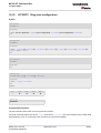
Case 5
Every UCS2 character is sent as 4 IRA characters and is converted into two 8-bit values. This means that the
first two characters have to be '00'.
Example: UCS2 character 009F'H typed as "009F" is sent as 30'H,30'H,39'H,46'H ® converted into 8-bit value
9F'H.
Maximum number of UCS2 characters is 140 which are represented by 560 IRA characters. Number of IRA characters must be a multiple of four.
Case 6
Every UCS2 character is sent as 4 IRA characters each and is converted into a 16-bit value again.
MC35i_ATC_V01.03
Confidential / Released
Page 24 of 444
5/7/04
MC35i AT Command Set
s
1.5 Supported character sets
mobile
Example: UCS2 character 9F3A'H typed as "9F3A" is sent as 39'H,46'H,33'H,41'H ® converted into 9F3A'H.
Maximum number of UCS2 characters is 70 which are represented by 280 IRA characters. Number of IRA characters must be a multiple of four.
Invalid UCS2 values must be prevented.
MC35i_ATC_V01.03
Confidential / Released
Page 25 of 444
5/7/04
MC35i AT Command Set
s
1.6 Serial Interface Flow Control
1.6
mobile
Serial Interface Flow Control
Flow control is essential to prevent loss of data or avoid errors when, in a data or fax call, the sending device is
transferring data faster than the receiving side is ready to accept. When the receiving buffer reaches its capacity,
the receiving device should be capable to cause the sending device to pause until it catches up.
There are basically two approaches to regulate data flow: Software flow control and hardware flow control. The
High Watermark of the input/output buffer should be set to approximately 60% of the total buffer size. The Low
Watermark is recommended to be about 30%. The data flow should be stopped when the capacity rises close to
the High Watermark and resumed when it drops below the Low Watermark. The time required to cause stop and
go results in a hysteresis between the High and Low Watermarks.
During Multiplex mode (AT+CMUX) it is recommended to use hardware flow control.
1.6.1
Software Flow Control (XON/OFF Handshake)
Software flow control sends different characters to stop (XOFF, decimal 19) and resume (XON, decimal 17) data
flow. The only advantage of software flow control is that three wires would be sufficient on the serial interface.
1.6.2
Hardware Flow Control (RTS/CTS Handshake)
Hardware flow control sets or resets the RTS/CTS wires. This approach is faster and more reliable, and therefore, the better choice. When the High Watermark is reached, CTS is set inactive until the transfer from the buffer
has completed. When the Low Watermark is passed, CTS goes active again.
To achieve smooth data flow, ensure that the RTS/CTS lines are present on your application platform. The application should include options to enable RTS/CTS handshake with the GSM engine. This needs to be done with
the AT command AT\Q3 - it is not sufficient to set RTS/CTS handshake in the used Terminal program only.
The default setting of the GSM engine is AT\Q0 (no flow control) which must be altered to AT\Q3 (RTS/CTS
hardware handshake on). The setting is stored volatile and must be restored each time after the GSM engine
was switched off.
AT\Q has no read command. To verify the current setting of AT\Q, simply check the settings of the active profile
with AT&V.
Often, fax programs run an intialization procedure when started up. The intialization commonly includes enabling
RTS/CTS hardware handshake, eliminating the need to set AT\Q3 once again. However, before setting up a
CSD call, you are advised to check that RTS/CTS handshake is set.
RTS/CTS hardware handshake must also be set if you want to take advantage of the CYCLIC SLEEP modes.
For further details refer to AT+CFUN.
Note: After deactivating the RTS line, the ME may still send up to 264 bytes (worst case). This can be easily
handled if the buffer of the host application is sufficiently sized, and if a hysteresis is implemented regarding its
Rx buffer. For host applications that are required to handle a large amount of data at high speed, a total buffer
capacity of 512 bytes is recommended.
MC35i_ATC_V01.03
Confidential / Released
Page 26 of 444
5/7/04
MC35i AT Command Set
s
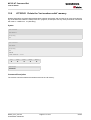
1.7 Unsolicited Result Code Presentation
1.7
mobile
Unsolicited Result Code Presentation
URC stands for Unsolicited Result Code and is a report message issued by the ME without being requested by
the TE, i.e. a URC is issued automatically when a certain event occurs. Hence, a URC is not issued as part of
the response related to an executed AT command.
Typical events leading to URCs are incoming calls ("RING"), waiting calls, received short messages, changes in
temperature, network registration etc.
A list of all URCs can be found in Section 19.6, Summary of Unsolicited Result Codes (URC).
To announce a pending URC transmission the ME will do the following:
•
Activates its Ring line (logic "1") for one second, i.e. the line changes to physical "Low" level. This allows the
TE to enter power saving mode until ME related events request service.
•
If the AT command interface is busy a "BREAK" will be sent immediately but the URC will not be issued until
the line is free. This may happen if the URC is pending
-
while an AT command is being processed, i.e. during the time from sending the first character "A" of an
AT command by the TE until the ME has responded with "OK" or "ERROR", or
-
during a data call.
Please note that AT command settings may be necessary to enable in-band signaling, e.g. refer to AT+CMER
or AT+CNMI.
It is strongly recommended to use the multiplex mode to map logical communication channels onto the serial line
of the MC35i, for details refer to [6] and AT command AT+CMUX. Doing so it is possible to use one channel to still
process URCs while having a data call active on another.
For most of these messages, the ME needs to be configured whether or not to send an URC. Depending on the
AT command, the URC presentation mode can be saved to the user defined profile (see AT&W), or needs to be
activated every time you reboot the ME. Several URCs are not user definable, such as "^SYSSTART",
"^SYSSTART <text>", "^SHUTDOWN" and the Fax Class 2 URCs listed in Section 19.6, Summary of Unsolicited Result Codes (URC).
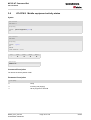
If autobauding is enabled (as factory default mode or set with AT+IPR=0), URCs generated after restart will be
output with 57600 bps until the ME has detected the current bit rate. The URCs "^SYSSTART", "^SYSSTART
<text>", however, are not presented at all. For details please refer to Section 4.7.1, Autobauding. To avoid problems we recommend to configure a fixed bit rate rather than using autobauding.
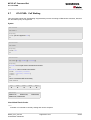
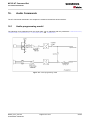
1.7.1
Communication between Customer Application and MC35i
Leaving hardware flow control unconsidered the Customer Application (TE) is coupled with the MC35i (ME) via
a receive and a transmit line.
Since both lines are driven by independent devices collisions may (and will) happen, i.e. while the TE issues an
AT command the MC35i starts sending an URC. This probably will lead to the TE's misinterpretation of the URC
being part of the AT command's response.
To avoid this conflict the following measures must be taken:
•
If an AT command is finished (with "OK" or "ERROR") the TE shall always wait at least 100 milliseconds
before sending the next one.
This gives the MC35i the opportunity to transmit pending URCs and get necessary service.
Note that some AT commands may require more delay after "OK" or "ERROR" response, refer to the following
command specifications for details.
•
The TE shall communicate with the MC35i using activated echo (ATE1), i.e. the MC35i echoes characters
received from the TE.
Hence, when the TE receives the echo of the first character "A" of the AT command just sent by itself it has
control over both the receive and the transmit paths. This way no URC can be issued by the MC35i in
between.
MC35i_ATC_V01.03
Confidential / Released
Page 27 of 444
5/7/04
MC35i AT Command Set
s
1.8 Errors and Messages
1.8
mobile
Errors and Messages
The final result codes "+CME ERROR: <err>" and "+CMS ERROR: <err>" indicate errors related to mobile equipment or network. The effect is similar to an ERROR result code.
A final result error code terminates the execution of the command and prevents the execution of all remaining
commands that may follow on the same command line. If so, neither ERROR nor OK result code are returned
for these commands. A 30 seconds timeout causes ERROR to be returned when the input of a command is not
complete.
The format of <err> can be either numeric or verbose. The setting is made with the command AT+CMEE.
See also:
•
Section 2.11.1, CME ERRORS related to GSM 07.07
•
Section 2.5.1, Verbose and numeric result codes
•
Section 3.4, AT+CEER
MC35i_ATC_V01.03
Confidential / Released
Page 28 of 444
5/7/04
MC35i AT Command Set
s
2. Configuration Commands
2.
mobile
Configuration Commands
The AT Commands described in this chapter allow the external application to determine the MC35i's behaviour
under various conditions.
2.1
AT&F Set all current parameters to manufacturer defaults
AT&F sets all current parameters to the manufacturer defined profile.
Syntax
Exec Command
AT&F[<value>]
Response(s)
OK
PIN
ASC0
MUX1
MUX2
MUX3
!
%
%
%
%
Reference(s)
V.25ter
Parameter Description
<value>(num)
[0]
Set all TA parameters to manufacturer defaults
Notes
•
List of parameters reset to manufacturer default can be found in Section 19.5, Factory Default Settings Restorable with AT&F.
•
In addition to the default profile, you can store an individual one with AT&W. To alternate between the two profiles enter either ATZ (loads user profile) or AT&F (restores factory profile).
•
Every ongoing or incoming call will be terminated.
MC35i_ATC_V01.03
Confidential / Released
Page 29 of 444
5/7/04
MC35i AT Command Set
s
2.2 AT&V
2.2
mobile
AT&V Display current configuration
AT&V returns the current parameter setting. The configuration varies depending on whether or not PIN authentication has been done and whether or not Multiplex mode is enabled (see AT+CMUX).
Syntax
Exec Command
AT&V[<value>]
Response(s)
ACTIVE PROFILE:
... (see Section 2.2.1, AT&V responses)
OK
PIN
ASC0
MUX1
MUX2
MUX3
!
%
%
§
§
Reference(s)
V.25ter
Parameter Description
<value>(num)
[0]
Profile number
Notes
•
The parameters of AT^SMGO can only be displayed after the SMS data from the SIM have been read successfully for the first time. Reading starts after successful SIM authentication has been performed, and may take
up to 30 seconds depending on the SIM used. While the read process is in progress, an attempt to read the
parameter will result in empty values.
•
The parameter of AT+CSDH will only be displayed in SMS text mode, see AT+CMGF.
2.2.1
AT&V responses
The following tables show four different kinds of responses depending on whether or not the PIN is entered and
whether or not the Multiplex mode is enabled (see AT+CMUX).
MC35i_ATC_V01.03
Confidential / Released
Page 30 of 444
5/7/04
MC35i AT Command Set
s
2.2 AT&V
Table 2.1:
mobile
Current configuration on ASC0 / MUX channel 1 (example)
PIN authentication done
No PIN authentication
ACTIVE PROFILE:
E1 Q0 V1 X4 &C1 &D2 &S0 \Q0
S0:000 S3:013 S4:010 S5:008 S6:000 S7:060 S8:000
S10:002 S18:000
+CBST: 7,0,1
+CRLP: 61,61,78,6
+CR: 0
+FCLASS: 0
+CRC: 0
+CMGF: 0
+CSDH: 0
+CNMI: 0,0,0,0,1
+ILRR: 0
+IPR: 57600
+CMEE: 2
^SMGO: 0,0
+CSMS: 0,1,1,1
^SACM: 0,"000000","000000"
^SCKS: 0,1
^SSET: 0
+CREG: 0,1
+CLIP: 0,2
+CAOC: 0
+COPS: 0,0,"operator"
+CGSMS: 3
OK
ACTIVE PROFILE:
E1 Q0 V1 X4 &C1 &D2 &S0 \Q0
S0:000 S3:013 S4:010 S5:008 S6:000 S7:060 S8:000
S10:002 S18:000
+CBST: 7,0,1
+CRLP: 61,61,78,6
+CR: 0
+FCLASS: 0
+ILRR: 0
+IPR: 57600
+CMEE: 2
^SCKS: 0,1
^SSET: 0
OK
Table 2.2:
Current configuration on MUX channels 2 and 3 (example)
PIN authentication done
No PIN authentication
ACTIVE PROFILE:
E1 Q0 V1 X4 &C1 &D0 &S0 \Q0
S0:000 S3:013 S4:010 S5:008
+CR: 0
+CRC: 0
+CMGF: 0
+CSDH: 0
+CNMI: 0,0,0,0,1
+ILRR: 0
+IPR: 57600
+CMEE: 2
^SMGO: 0,0
+CSMS: 0,1,1,1
^SACM: 0,"000000","000000"
^SCKS: 0,1
^SSET: 0
+CREG: 0,1
+CLIP: 0,2
+CAOC: 0
+COPS: 0,0,"operator"
+CGSMS: 3
OK
ACTIVE PROFILE:
E1 Q0 V1 X4 &C1 &D0 &S0 \Q0
S0:000 S3:013 S4:010 S5:008
+CR: 0
+ILRR: 0
+IPR: 57600
+CMEE: 2
^SCKS: 0,1
^SSET: 0
+CGSMS: 3
OK
MC35i_ATC_V01.03
Confidential / Released
Page 31 of 444
5/7/04
MC35i AT Command Set
s
2.3 AT&W
2.3
mobile
AT&W Stores current configuration to user defined profile
AT&W stores the currently set parameters to a user defined profile in the non-volatile memory.
Syntax
Exec Command
AT&W[<value>]
Response(s)
OK
ERROR/+CME ERROR <err>
PIN
ASC0
MUX1
MUX2
MUX3
!
%
%
%
%
Reference(s)
V.25ter
Parameter Description
<value>(num)
[0]
Number of profile
Notes
•
The user defined profile will be restored automatically after power-up. Use ATZ to restore user profile and
AT&F to restore factory settings. Until the first use of AT&W, ATZ works as AT&F.
•
User defined profiles in multiplex mode:
AT&W stores the current setting of each channel to the user profile, no matter on which of the three channels
the command is executed. Each channel may have an individual profile.
•
A list of parameters stored to the user profile can be found in Section 19.4, AT Command Settings storable with AT&W.
MC35i_ATC_V01.03
Confidential / Released
Page 32 of 444
5/7/04
MC35i AT Command Set
s
2.4 ATQ
2.4
mobile
ATQ Set result code presentation mode
This parameter setting determines whether or not the TA transmits any result code to the TE. Information text
transmitted in response is not affected by this setting.
Syntax
Exec Command
ATQ[<n>]
Response(s)
If <n>=0:
OK
If <n>=1:
(none)
PIN
ASC0
MUX1
MUX2
MUX3
!
%
%
%
%
Reference(s)
V.25ter
Parameter Description
<n>(num)(&W)(&V)
[0](&F)
DCE transmits result code
1
Result codes are suppressed and not transmitted
MC35i_ATC_V01.03
Confidential / Released
Page 33 of 444
5/7/04
MC35i AT Command Set
s
2.5 ATV
2.5
mobile
ATV Set result code format mode
This command determines the contents of header and trailer transmitted with AT command result codes and
information responses. Possible responses are described in Section 2.5.1, Verbose and numeric result codes.
Syntax
Exec Command
ATV[<value>]
Response(s)
OK
ERROR
PIN
ASC0
MUX1
MUX2
MUX3
!
%
%
%
%
Reference(s)
V.25ter
Parameter Description
<value>(num)(&W)(&V)
[0]
Information response: <text><CR><LF>
Short result code format: <numeric code><CR>
1(&F)
Information response: <CR><LF><text><CR><LF>
Long result code format: <CR><LF><verbose code><CR>
2.5.1
Verbose and numeric result codes
Verbose format
Numeric format
Meaning
OK
0
Command executed, no errors
CONNECT
1
Link established
RING
2
Ring detected
NO CARRIER
3
Link not established or disconnected
ERROR
4
Invalid command or command line too
long
NO DIALTONE
6
No dial tone, dialling impossible, wrong
mode
BUSY
7
Remote station busy
CONNECT 2400/RLP
47
Link with 2400 bps and Radio Link Protocol
MC35i_ATC_V01.03
Confidential / Released
Page 34 of 444
5/7/04
MC35i AT Command Set
s
2.5 ATV
mobile
Verbose format
Numeric format
Meaning
CONNECT 4800/RLP
48
Link with 4800 bps and Radio Link Protocol
CONNECT 9600/RLP
49
Link with 9600 bps and Radio Link Protocol
CONNECT 14400/RLP
50
Link with 14400 bps and Radio Link Protocol
ALERTING
Alerting at called phone
DIALING
Mobile phone is dialing
MC35i_ATC_V01.03
Confidential / Released
Page 35 of 444
5/7/04
MC35i AT Command Set
s
2.6 ATX
2.6
mobile
ATX Set CONNECT result code format and call monitoring
ATX determines whether or not the TA detects the presence of dial tone and busy signal and whether or not TA
transmits particular result codes.
Syntax
Exec Command
ATX[<value>]
Response(s)
OK
ERROR
PIN
ASC0
MUX1
MUX2
MUX3
!
%
%
%
%
Reference(s)
V.25ter
Parameter Description
<value>(num)(&W)(&V)
[0]
CONNECT result code only returned, dial tone and busy detection are both disabled.
1
CONNECT <text> result code only returned, dial tone and busy detection are
both disabled.
2
CONNECT <text> result code returned, dial tone detection is enabled, busy
detection is disabled.
3
CONNECT <text> result code returned, dial tone detection is disabled, busy
detection is enabled.
4(&F)
CONNECT <text> result code returned, dial tone and busy detection are both
enabled.
MC35i_ATC_V01.03
Confidential / Released
Page 36 of 444
5/7/04
MC35i AT Command Set
s
2.7 ATZ
2.7
mobile
ATZ Set all current parameters to user defined profile
ATZ sets all current parameters to the user profile stored with AT&W. If a connection is in progress, it will be terminated.
All defined GPRS contexts which are not activated or not online will be undefined (see AT+CGDCONT,
AT+CGQREQ and AT+CGQMIN command).
The user defined profile is stored to the non-volatile memory.
Syntax
Exec Command
ATZ[<value>]
Response(s)
OK
PIN
ASC0
MUX1
MUX2
MUX3
!
%
%
%
%
Reference(s)
V.25ter
Parameter Description
<value>(num)
[0]
Reset to user profile
Notes
•
First the profile will be set to factory default (see AT&F). If there is a valid user profile (stored with AT&W), this
profile will be loaded afterwards.
•
Any additional commands on the same command line may be ignored. A delay of 300 ms is required before
next command is sent, otherwise "OK" response may be corrupted.
MC35i_ATC_V01.03
Confidential / Released
Page 37 of 444
5/7/04
MC35i AT Command Set
s
2.8 AT+CFUN
2.8
mobile
AT+CFUN Set phone functionality
This command serves to control the functionality level of the ME. It can be used to reset the ME, to choose one
of the SLEEP modes or to return to full functionality.
Intended for power saving, SLEEP mode reduces the functionality of the ME to a minimum and thus minimizes
the current consumption. SLEEP mode falls in two categories:
•
NON-CYCLIC SLEEP mode <fun>=0
•
and CYCLIC SLEEP modes, selectable as <fun>= 5, 6, 7 or 8.
NON-CYCLIC SLEEP mode permanently blocks the serial interface. The CYCLIC SLEEP mode, however, is a
dynamic process which alternatingly enables and disables the serial interface. The major benefit of all CYCLIC
SLEEP modes is that the serial interface remains accessible and that, in intermittent wake-up periods, characters
can be sent or received without terminating the selected mode. The best choice is using <fun>= 5, 6, 7 or 8,
since in these modes MC35i automatically resumes power saving, after you have sent or received a short message or made a call. <fun>=5 or 6 do not offer this feature to the same extent and are only supported for compatibility with earlier releases. In all CYCLIC SLEEP modes, you can enter <fun>=1 to permanently wake up
MC35i and take it back to full functionality. Please refer to Section 2.8.1, Wake up the ME from SLEEP mode for
a summary of all SLEEP modes and the different ways of waking up the module.
For CYCLIC SLEEP mode (<fun>= 5, 6, 7 or 8) both the ME and the application must be configured to use hardware flow control. This is necessary since the CTS signal is set/reset every time when the ME listens to a paging
message from the base station. This is the way how the module indicates to the application when the UART is
active. For detailed information on the timing of the CTS signal refer to [2]. The default setting of hardware flow
control is AT\Q0 which must be altered to AT\Q3. For use after restart you are advised to add it to the user profile
saved with AT&W.
Syntax
Test Command
AT+CFUN=?
Response(s)
+CFUN: (list of supported <fun>s) , (list of supported <rst>s)
OK
Read Command
AT+CFUN?
Response(s)
+CFUN: <fun>
OK
Write Command
AT+CFUN=[<fun>[, <rst>]]
Response(s)
OK
ERROR
+CME ERROR
MC35i_ATC_V01.03
Confidential / Released
Page 38 of 444
5/7/04
MC35i AT Command Set
s
2.8 AT+CFUN
mobile
PIN
ASC0
MUX1
MUX2
MUX3
!
%
§
§
§
Reference(s)
GSM 07.07
Command Description
The test command returns the values of the supported parameters.
The read command returns the current functionality value.
The write command can be used to reset the ME, to choose one of the SLEEP modes or to return to full functionality.
Parameter Description
<fun>(num)
0
NON-CYCLIC SLEEP mode:
In this mode, the AT interface is not accessible. Consequently, once you have
set <fun> level 0, do not send further characters. Otherwise these characters
remain in the input buffer and may delay the output of an unsolicited result
code.
The first wake-up event stops power saving and takes the ME back to full functionality level <fun>=1.
[1](&F)
Full functionality.
If the ME is in one of the CYCLIC SLEEP modes you can issue AT+CFUN=1
to stop power saving and return to full functionality.
Keep in mind that, unlike the reset command described below, this action does
not restart the ME but only changes the level of functionality. See parameter
<rst> for details on the reset.
5
CYCLIC SLEEP mode:
In this mode, the serial interface is shortly enabled during paging. If characters
are recognized on the serial interface, the ME stays active for 2 seconds after
the last character was sent or received.
6
CYCLIC SLEEP mode:
In this mode, the serial interface is shortly enabled during paging.
If characters are recognized on the serial interface, the ME stays active for 10
minutes after the last character was sent or received.
To ensure that power saving takes effect immediately, the ME stays active for
only 2 seconds after <fun>=6 was entered.
MC35i_ATC_V01.03
Confidential / Released
Page 39 of 444
5/7/04
MC35i AT Command Set
s
2.8 AT+CFUN
mobile
7
CYCLIC SLEEP mode:
In this mode, the serial interface is shortly enabled during paging. If characters
are recognized on the serial interface, the ME stays active for 2 seconds after
the last character was sent or received. ME exits SLEEP mode only, if
AT+CFUN=1 is entered.
8
CYCLIC SLEEP mode:
In this mode, the serial interface is shortly enabled during paging.
If characters are recognized on the serial interface, the ME stays active for 10
minutes after the last character was sent or received. ME exits SLEEP mode
only, if AT+CFUN=1 is entered.
To ensure that power saving takes effect immediately, the ME stays active for
only 2 seconds after <fun>=8 was entered.
<rst>(num)
The parameter can only be used if the serial interface is enabled.
Due to the command syntax, you need to enter parameter <fun>, followed by <rst>, where <fun> is only a
placeholder and has no effect. See examples below.
[0]
Placeholder for <fun> as stated above.
1
ME resets and restarts to full functionality. After reset and restart, PIN 1
authentication is necessary (AT+CPIN). If autobauding is enabled, it is recommended to wait 3 to 5 seconds before entering the first AT command. For
details on autobauding refer to "Section 4.7.1, Autobauding".
Notes
•
In Multiplex mode, the CFUN profile is shared by all multiplexer channels.
•
If the ME is in Multiplexer mode, it is not recommended to activate SLEEP mode with AT+CFUN=<fun>. The
best approach to properly control SLEEP mode in this case is to issue the PSC messages described in [6],
Section "Power saving control".
•
When a circuit-switched call is in progress, <fun>=7 or 8 can be activated without terminating the call. However, setting <fun>=0, 5 or 6 during a circuit-switched call immediately disconnects this call.
•
Please keep in mind that power saving works properly only when PIN authentication has been done. If you
attempt to activate power saving while the SIM card is not inserted or the PIN is not correctly entered, the
selected <fun> level will be set, though power saving does not take effect. For the same reason, power saving cannot be used if MC35i operates in Alarm mode. Furthermore, in order to accept incoming calls, SMS or
network related URCs in SLEEP mode the ME must be registered when it enters the SLEEP mode.
•
To check whether power saving is on, you can query the status with the read command AT+CFUN? only if
the module is in full functionality mode or in CYCLIC SLEEP mode. If available, you can also take advantage
of the status LED controlled by the SYNC pin (see AT^SSYNC and [2]). The LED remains "off" while the module is in any of the SLEEP modes. However, the module can wake up temporarily from power saving without
leaving its CYCLIC SLEEP mode (without changing +CFUN "<fun>"), e.g. for a network scan after a loss of
radio coverage, or after receipt of serial data during CYCLIC SLEEP mode. During this "temporary wakeup
state" the LED will operate as if the ME was in full functionality mode.
•
Recommendation: In NON-CYCLIC SLEEP mode, you can set an RTC alarm to wake up the ME and return
to full functionality. This is a useful approach because, in this mode, the AT interface is not accessible.
MC35i_ATC_V01.03
Confidential / Released
Page 40 of 444
5/7/04
MC35i AT Command Set
s
2.8 AT+CFUN
mobile
Examples
EXAMPLE 1
To check the level of functionality use the read command:
AT+CFUN?
+CFUN: 1
Default mode after ME was restarted
Remember that the AT interface is not accessible in NON-CYCLIC SLEEP mode. Consequently, the read
command is only useful when the ME is set to full functionality or, when <fun> is set to 5, 6, 7 or 8.
AT+CFUN?
+CFUN: 5
CYCLIC SLEEP mode
EXAMPLE 2
To set the ME to NON-CYCLIC SLEEP mode enter
AT+CFUN=0
OK
When, for example, an SMS is being received and indicated by an unsolicited result code (URC), the ME
wakes up to full operation.
+CMTI: "SM",5
Note that the URC used in this example will appear only, if AT+CNMI=1,1 was configured before.
After this, you may want to verify the operating status:
AT+CFUN?
+CFUN: 1
Indicates that ME has entered full functionality mode.
EXAMPLE 3
To stop CYCLIC SLEEP mode and return to full functionality:
AT+CFUN?
+CFUN: 5
OK
AT+CFUN=1
OK
Remember that this approach is not applicable to the NON-CYCLIC SLEEP mode (since the serial interface
is disabled). The NON-CYCLIC SLEEP mode ends with the first wake-up event.
EXAMPLE 4
To reset and restart the ME:
AT+CFUN=1,1
or alternatively, AT+CFUN=0,1 or 5,1 or 6,1 or 7,1 or 8,1
OK
^SYSSTART
MC35i_ATC_V01.03
Confidential / Released
The ^SYSSTART URC confirms that the ME has been rebooted. Note
that ^SYSSTART appears only if AT+IPR ¹ 0. If the ME is in autobaud
mode, it is recommended to wait 3 to 5 seconds before entering the first
AT command. Remember to enter the SIM PIN after restart.
Page 41 of 444
5/7/04
MC35i AT Command Set
s
2.8 AT+CFUN
2.8.1
mobile
Wake up the ME from SLEEP mode
A wake-up event is any event that causes the ME to draw current. Depending on the selected mode, the wakeup event either switches the SLEEP mode off and takes the ME back to full functionality AT+CFUN=1, or activates
the ME temporarily without terminating the selected SLEEP mode.
Definitions of the state transitions described in Table 2.3, Wake-up events in NON-CYCLIC and CYCLIC SLEEP
modes:
•
Quit: ME exits SLEEP mode.
•
Temporary: ME becomes active temporarily for the duration of the event and the mode-specific follow-up time
after the last character was sent or received on the serial interface.
•
No effect: Event is not relevant in the selected SLEEP mode. The ME does not wake up.
Table 2.3:
Wake-up events in NON-CYCLIC and CYCLIC SLEEP modes
Event
Selected mode:
<fun>=0
Selected mode:
<fun>=5 or 6
Selected mode:
<fun>=7 or 8
Ignition line
No effect
No effect
No effect
/RTS0
Quit
No effect (RTS is only
used for flow control)
No effect (RTS is only
used for flow control)
Unsolicited Result Code
(URC)
Quit
Quit
Temporary
Incoming voice or data
call
Quit
Quit
Temporary
Any AT command (incl.
outgoing SMS, voice or
data call)
Not possible (UART disabled)
Temporary
Temporary
Incoming SMS (AT+CNMI
is set to 0,0 (this is the
default setting)
No effect
No effect
No effect
Incoming SMS (AT+CNMI
is set to 1,1)
Quit
Quit
Temporary
GPRS data transfer
Not possible (UART disabled)
Temporary
Temporary
RTC alarm line
Quit
Quit
Temporary
AT+CFUN=1
Not possible (UART disabled)
Quit
Quit
MC35i_ATC_V01.03
Confidential / Released
Page 42 of 444
5/7/04
MC35i AT Command Set
s
2.9 AT^SMSO
2.9
mobile
AT^SMSO Switch off mobile station
AT^SMSO initiates the power-off procedure. Low level of the module's VDD pin and the URC "^SHUTDOWN" verifies that the procedure has completed and the module has entered the POWER DOWN mode. Therefore, be
sure not to disconnect the operating voltage until VDD is low or until the URC "^SHUTDOWN" is displayed. Otherwise, you run the risk of losing data. For further details on how to turn off the module see the [2].
Syntax
Test Command
AT^SMSO=?
Response(s)
OK
Exec Command
AT^SMSO
Response(s)
^SMSO: MS OFF
OK
PIN
ASC0
MUX1
MUX2
MUX3
!
%
%
%
%
Reference(s)
SIEMENS
Unsolicited Result Code
^SHUTDOWN
Indicates that the power-off procedure is finished and the module will be switched off within 1 second.
Notes
•
Do not send any other AT command after AT^SMSO.
•
If AT^SMSO is entered on one of the Multiplexer channels the ME closes the Multiplexer channels, terminates
the Multiplexer and deactivates all other functions. Then, the URC "^SHUTDOWN" will be issued on the physical serial interface (ASC0). The URC will be transmitted at the bit rate last activated on ASC0 for use with
the Multiplex driver.
MC35i_ATC_V01.03
Confidential / Released
Page 43 of 444
5/7/04
MC35i AT Command Set
s
2.10 AT+GCAP
2.10
mobile
AT+GCAP Request complete TA capabilities list
AT+GCAP returns a list of additional capabilities.
Syntax
Test Command
AT+GCAP=?
Response(s)
OK
Exec Command
AT+GCAP
Response(s)
+GCAP: <name>
OK
PIN
ASC0
MUX1
MUX2
MUX3
!
%
%
%
%
Reference(s)
V.25ter
Parameter Description
<name>(str)
e.g.: +CGSM,+FCLASS
Note
•
+CGSM: The response text shows which GSM commands of the ETSI standard are supported.
MC35i_ATC_V01.03
Confidential / Released
Page 44 of 444
5/7/04
MC35i AT Command Set
s
2.11 AT+CMEE
2.11
mobile
AT+CMEE Mobile Equipment Error Message Format
AT+CMEE controls the format of the error result code +CME ERROR: <err> that indicates errors relating to ME
functionality.
Possible error result codes are listed in Section 2.11.1, CME ERRORS related to GSM 07.07, Section 2.11.2,
GPRS-related CME ERRORS and Section 2.11.3, CMS ERRORS related to GSM 07.05.
In multiplex mode (refer AT+CMUX) the setting applies only to the logical channel where selected. The setting on
the other channels may differ.
Syntax
Test Command
AT+CMEE=?
Response(s)
+CMEE: (list of supported<errMode>s)
OK
Read Command
AT+CMEE?
Response(s)
+CMEE: <errMode>
OK
Write Command
AT+CMEE=<errMode>
Response(s)
OK
ERROR
+CME ERROR: <err>
PIN
ASC0
MUX1
MUX2
MUX3
!
%
%
%
%
Reference(s)
GSM 07.07
Parameter Description
<errMode>(num)(&W)(&V)
0(&F)
Disable result code (only 'ERROR' will be displayed).
1
Enable error result code with numeric values.
2
Enable error result code with verbose (string) values.
MC35i_ATC_V01.03
Confidential / Released
Page 45 of 444
5/7/04
MC35i AT Command Set
s
2.11 AT+CMEE
mobile
Example
To obtain enhanced error messages it is recommended to choose <errMode>=2.
AT+CMEE=2
OK
2.11.1
CME ERRORS related to GSM 07.07
Code of <err>
Text (if AT+CMEE=2)
0
phone failure
1
no connection to phone
2
phone-adapter link reserved
3
Operation not allowed
4
Operation not supported
5
PH-SIM PIN required
6
PH-FSIM PIN required
7
PH-FSIM PUK required
10
SIM not inserted
11
SIM PIN required
12
SIM PUK required
13
SIM failure
14
SIM busy
15
SIM wrong
16
Incorrect password
17
SIM PIN2 required
18
SIM PUK2 required
20
Memory full
21
invalid index
22
not found
23
Memory failure
24
text string too long
25
invalid characters in text string
26
dial string too long
27
invalid characters in dial string
30
no network service
31
Network timeout
32
Network not allowed emergency calls only
MC35i_ATC_V01.03
Confidential / Released
Page 46 of 444
5/7/04
MC35i AT Command Set
s
2.11 AT+CMEE
mobile
Code of <err>
Text (if AT+CMEE=2)
40
Network personalization PIN required
41
Network personalization PUK required
42
Network subset personalization PIN required
43
Network subset personalization PUK required
44
service provider personalization PIN required
45
service provider personalization PUK required
46
Corporate pe sonalization PIN required
47
Corporate personalization PUK required
48
Master Phone Code required
100
unknown
132
service option not supported
133
requested service option not subscribed
134
service option temporarily out of order
256
Operation temporary not allowed
257
call barred
258
phone is busy
259
user abort
260
invalid dail string
261
ss not executed
262
SIM blocked
2.11.2
GPRS-related CME ERRORS
Code of <err>
Text (if AT+CMEE=2)
103
Illegal MS
106
Illegal ME
107
GPRS services not allowed
111
PLMN not allowed
112
Location area not allowed
113
Roaming not allowed in this location area
148
unspecified GPRS error
149
PDP authentication failure
150
invalid mobile class
MC35i_ATC_V01.03
Confidential / Released
Page 47 of 444
5/7/04
MC35i AT Command Set
s
2.11 AT+CMEE
2.11.3
mobile
CMS ERRORS related to GSM 07.05
Code of <err>
Text (if AT+CMEE=2)
1
Unassigned (unallocated) number
8
Operator determined barring
10
Call barred
21
Short message transfer rejected
27
Destination out of service
28
Unidentified subscriber
29
Facility rejected
30
Unknown subscriber
38
Network out of order
41
Temporary failure
42
Congestion
47
Resources unavailable, unspecified
50
Requested facility not subscribed
69
Requested facility not implemented
81
Invalid short message transfer reference value
95
Invalid message, unspecified
96
Invalid mandatory information
97
Message type non-existent or not implemented
98
Message not compatible with short message protocol state
99
Information element non-existent or not implemented
111
Protocol error, unspecified
127
Interworking, unspecified
128
Telematic interworking not supported
129
Short message Type 0 not supported
130
Cannot replace short message
143
Unspecified TP-PID error
144
Data coding scheme (alphabet) not supported
145
Message class not supported
159
Unspecified TP-DCS error
160
Command cannot be actioned
161
Command unsupported
175
Unspecified TP-Command error
176
TPDU not supported
192
SC busy
193
No SC subscription
MC35i_ATC_V01.03
Confidential / Released
Page 48 of 444
5/7/04
MC35i AT Command Set
s
2.11 AT+CMEE
mobile
Code of <err>
Text (if AT+CMEE=2)
194
SC system failure
195
Invalid SME address
196
Destination SME barred
197
SM Rejected-Duplicate SM
198
TP-VPF not supported
199
TP-VP not supported
208
D0 SIM SMS storage full
209
No SMS storage capability in SIM
210
Error in MS
211
Memory Capacity Exceeded
212
SIM Application Toolkit Busy
213
SIM data download error
255
Unspecified error cause
300
ME failure
301
SMS service of ME reserved
302
Operation not allowed
303
Operation not supported
304
Invalid PDU mode parameter
305
Invalid text mode parameter
310
SIM not inserted
311
SIM PIN required
312
PH-SIM PIN required
313
SIM failure
314
SIM busy
315
SIM wrong
316
SIM PUK required
317
SIM PIN2 required
318
SIM PUK2 required
320
Memory failure
321
Invalid memory index
322
Memory full
330
SMSC address unknown
331
no network service
332
Network timeout
340
NO +CNMA ACK EXPECTED
500
Unknown error
512
User abort
MC35i_ATC_V01.03
Confidential / Released
Page 49 of 444
5/7/04
MC35i AT Command Set
s
2.11 AT+CMEE
mobile
Code of <err>
Text (if AT+CMEE=2)
513
unable to store
514
invalid status
515
invalid character in address string
516
invalid length
517
invalid character in pdu
518
invalid parameter
519
invalid length or character
520
invalid character in text
521
timer expired
522
Operation temporary not allowed
MC35i_ATC_V01.03
Confidential / Released
Page 50 of 444
5/7/04
MC35i AT Command Set
s
2.12 AT+CSCS
2.12
mobile
AT+CSCS Select TE character set
The AT+CSCS write command informs the TA which character set <chset> is used by the TE. This enables the
TA to convert character strings correctly between TE and ME character sets. See also "Section 1.5, Supported
character sets".
Note that when the TA-TE interface is set to 8-bit operation and the used TE alphabet is 7-bit, the highest bit will
be set to zero.
Syntax
Test Command
AT+CSCS=?
Response(s)
+CSCS: (list of supported<chset>s)
OK
Read Command
AT+CSCS?
Response(s)
+CSCS: <chset>
OK
Write Command
AT+CSCS=[<chset>]
Response(s)
OK
PIN
ASC0
MUX1
MUX2
MUX3
!
%
%
%
%
Reference(s)
GSM 07.07, GSM 11.11
MC35i_ATC_V01.03
Confidential / Released
Page 51 of 444
5/7/04
MC35i AT Command Set
s
2.12 AT+CSCS
mobile
Parameter Description
<chset>(str)
“GSM“(&F)
GSM default alphabet (GSM 03.38 subclause 6.2.1);
Note: This setting may cause software flow control problems since the codes
used to stop and resume data flow (XOFF = decimal 19, XON = decimal 17)
are interpreted as normal characters.
“UCS2“
16-bit universal multiple-octet coded character set (ISO/IEC10646 [32]); UCS2
character strings are converted to hexadecimal numbers from 0000 to FFFF;
e.g. "004100620063" equals three 16-bit characters with decimal values 65, 98
and 99, $(AT R97)$
MC35i_ATC_V01.03
Confidential / Released
Page 52 of 444
5/7/04
MC35i AT Command Set
s
2.13 AT^SM20
2.13
mobile
AT^SM20 Set M20 compatibility mode
M20 is an earlier, widely used SIEMENS GSM engine. The AT^SM20 command selects different modes of
responses returned upon execution of the commands ATD and sms commands like e.g. AT+CMGW. Please note
that the AT^SM20 command has no effect on any other features and is not intended to adjust other differences
between M20 and MC35i.
Syntax
Test Command
AT^SM20=?
Response(s)
OK
Read Command
AT^SM20?
Response(s)
^SM20:<CallMode>, <CmgwMode>
OK
Write Command
AT^SM20=<CallMode>[, <CmgwMode>]
Response(s)
OK
PIN
ASC0
MUX1
MUX2
MUX3
!
%
%
%
%
Reference(s)
SIEMENS
MC35i_ATC_V01.03
Confidential / Released
Page 53 of 444
5/7/04
MC35i AT Command Set
s
2.13 AT^SM20
mobile
Parameter Description
<CallMode>(num)
Call setup response mode
Applies only to voice calls.
0
Set compatibility to Siemens mobile phones.
ME will return "OK" immediately after attempting a call with the ATD command.
In case of failure, additional call release indications, such as "NO DIAL TONE,
"NO CARRIER", "BUSY" will follow.
1(&F)
Default call setup mode, compatible to M20.
ME will return "OK" in case of a successful connection, otherwise one of the
call release indications "NO DIAL TONE, "NO CARRIER", "BUSY" are indicated.
<CmgwMode>(num)
Response mode for sending and writing short messages
Applies to the sms commands like e.g. AT+CMGS and AT+CMGW command.
0
Set compatibility to Siemens mobile phones.
ME will return +CMS ERROR: <err> when writing or sending of short messages fails.
1(&F)
Default mode for sending and writing short messages, compatible to M20.
ME will return "OK", no matter whether or not sms command was successfully
executed.
MC35i_ATC_V01.03
Confidential / Released
Page 54 of 444
5/7/04
MC35i AT Command Set
s
3. Status Control Commands
3.
mobile
Status Control Commands
The AT Commands described in this chapter allow the external application to obtain various status information
from the MC35i.
3.1
AT+CMER Mobile Equipment Event Reporting
This command controls details of the "+CIEV" URC presentation related to AT^SIND and AT+CIND. If registered
via these commands the URCs are sent whenever a value of the related indicator changes.
After AT+CMER has been switched on, URCs for all registered indicators will be issued.
Syntax
Test Command
AT+CMER=?
Response(s)
+CMER: (list of supported<mode>s), (list of supported <keyp>s), (list of supported <disp>s), (list of
supported <ind>s), (list of supported <bfr>s)
OK
Read Command
AT+CMER?
Response(s)
+CMER: <mode>, <keyp>, <disp>, <ind>, <bfr>
OK
Write Command
AT+CMER=[<mode>[, <keyp>[, <disp>[, <ind>[, <bfr>]]]]]
Response(s)
OK
ERROR
+CME ERROR
PIN
ASC0
MUX1
MUX2
MUX3
%
%
%
%
%
Reference(s)
GSM 07.07
MC35i_ATC_V01.03
Confidential / Released
Page 55 of 444
5/7/04
MC35i AT Command Set
s
3.1 AT+CMER
mobile
Unsolicited Result Code
+CIEV: <indDescr>, <indValue>
A value of an indicator has changed.
Command Description
The read command returns the URC presentation mode <mode> and among others, the indicator event reporting
status <ind>.
The write command enables and disables the presentation of "+CIEV: <indDescr>, <indValue>" URCs.
<indDescr> refers to the name of a "+CIEV" indicator and <indValue> is the new value of this indicator. All
registered indicator events will be issued to the TE.
Parameter Description
<mode>(num)
0(&F)
Discard "+CIEV" URCs.
1
Discard "+CIEV" URCs when TA-TE link is reserved, e.g. in online data mode.
Otherwise they are forwarded directly to the TE.
2
Buffer "+CIEV" URCs in the TA while TA-TE link is reserved, e.g. in online data
mode, and flush them to the TE afterwards. Otherwise they are forwarded
directly to the TE.
3
Forward "+CIEV" URCs directly to the TE. If MC35i is in online data mode,
URCs are signaled via sending BREAK (100ms) and stored in a buffer. Once
it is back in command mode e.g. after +++ was entered, all URCs stored in the
buffer will be output.
<keyp>(num)
0(&F)
Keypad event reporting is not supported by MC35i.
<disp>(num)
0(&F)
Display event reporting is not supported by MC35i.
<ind>(num)
0(&F)
Disable indicator event reporting.
2
Enable indicator event reporting.
<bfr>(num)
0(&F)
TA buffer of URCs defined within this command is cleared when <mode> 1..3
is entered.
<indDescr>(str)
Name of indicator; for a list of all supported indicators please refer to AT+CIND and AT^SIND.
<indValue>(num)
Value of indicator; for a list of all values for the supported indicators please refer to AT+CIND and AT^SIND.
MC35i_ATC_V01.03
Confidential / Released
Page 56 of 444
5/7/04
MC35i AT Command Set
s
3.1 AT+CMER
mobile
Note
•
If the ME operates on different instances (MUX channels 1, 2, 3) avoid different settings for routing and indicating SMS. For example, if messages shall be routed directly to one instance of the TE (set with AT+CNMI,
AT^SSDA), it is not possible to activate the presentation of URCs with AT+CMER or AT+CNMI on another
instance. Any attempt to activate settings that conflict with existing settings on another interface, will result in
CME ERROR, or accordingly CMS ERROR.
MC35i_ATC_V01.03
Confidential / Released
Page 57 of 444
5/7/04
MC35i AT Command Set
s
3.2 AT+CIND
3.2
mobile
AT+CIND Indicator control
This command controls information about status changes via URC presentation of the MC35i or connected
items, e.g. battery charge level, signal quality, service availability, sound generation, indication of unread short
messages, full SMS storage, call in progress or roaming activities.
Use of this command is outdated since additional indications and functionality are available with AT^SIND.
AT+CIND supports two ways to get the values related to indicators:
•
Query the current status of each indicator by using the read command AT+CIND?. It returns the status no
matter
whether
the
indicator
has
been
registered
with
the
write
command
AT+CIND=[<state>[,<state>[,...]]].
•
Evaluate one of the "+CIEV" URCs which the ME automatically sends to the application, whenever the value
of the associated indicator changes.
The presentation of these URCs depends on two settings:
-
The indicators must be registered with the write command AT+CIND=[<state>[,<state>[,...]]]. By
default, all of them are registered when the ME is switched on. Any URC can be excluded if deregistered
with <state>=0.
-
URC presentation must be enabled with AT+CMER.
Syntax
Test Command
AT+CIND=?
Response(s)
+CIND: (<indDescr>, list of supported <indValue>s)[, (<indDescr>, list of supported <indValue>s)[,
...]]
OK
Read Command
AT+CIND?
Response(s)
+CIND: <indValue>[, <indValue>[, ...]]
OK
ERROR
+CME ERROR: <err>
Write Command
AT+CIND=<state>[, <state>[, ...]]
Response(s)
OK
ERROR
+CME ERROR: <err>
MC35i_ATC_V01.03
Confidential / Released
Page 58 of 444
5/7/04
MC35i AT Command Set
s
3.2 AT+CIND
mobile
PIN
ASC0
MUX1
MUX2
MUX3
!
%
%
%
%
Reference(s)
GSM 07.07
Command Description
The read command returns the status of the ME indicators.
The write command is used to switch the event report for each indicator type. The Indicator Event Reports are
displayed to the TE via "+CIEV" which can be enabled using AT+CMER.
Parameter Description
<indValue>(num)
Integer type value, which shall be in range of corresponding <indDescr>
<indDescr>(str)
String values and their <indValue> ranges.
More indications are available via AT^SIND. Therefore use of AT^SIND for control of all indications is recommended.
The following indications are accessible via AT+CIND:
“battchg“
Battery charge level always equals 5, i.e. value is not relevant for MC35i
“signal“
Signalquality (0..7) or (99) if not measurable. The indicated value is the bit error
rate of the signal received. If there are bit errors this is not a constant but a estimated value which will change in time. See also AT+CSQ.
“service“
Service availability (0-1)
0: Not registered to any network
1: Registered to home network or, if "roam"=1 then registered to another network
“sounder“
Sounder activity (0-1). The indicator provides information about tones generated in the ME. Value 1 means for example:
Incoming call - ME is ringing. Note that the URC "+CIEV: sounder" indicator will
be output only if ringing tones are activated with AT^SRTC.
Waiting call - ME generates waiting call tone (if call waiting is enabled).
Outgoing call - ME generates Call Progress tone.
Outgoing call - ME generates BUSY tone.
The value changes to 0 if tone stops
“message“
Unread short message at memory location <mem1> (0-1); refer to AT+CPMS
“call“
Call in progress (0-1). Indicator value is "1" if at least one call is in state "active"
or "held".
“roam“
Roaming indicator (0-1)
0: Registered to home network or not registered
1: Registered to other network
MC35i_ATC_V01.03
Confidential / Released
Page 59 of 444
5/7/04
MC35i AT Command Set
s
3.2 AT+CIND
mobile
“smsfull“
A short message memory storage in the MT has become full (1) or memory
locations are available (0), i.e. range is (0-1)
“rssi“
Received signal (field) strength (0..5) or (99) if not measurable.
0: signal strength <= -112 dbm
1-4: signal strength in 15 dbm steps
5: signal strength >= -51 dbm
Received signal (field) strength can also be obtained with AT+CSQ. However,
the signal strength is scaled to value range 0..31 by this command.
<state>(num)
0
Indicator is deregistered. The indicator will not be presented as "+CIEV" URC,
but can be queried with AT+CIND?.
[1](P)
Indicator is registered, indicator event report allowed.
Notes
•
Due to its restrictive range of values, there are events when it is not entirely clear from the context, which
event has led to the output of indicator "call". Rather than as an information in itself, indicator "call" should
therefore be used as a trigger to look up the new call status in the list of current calls with AT commands
AT+CLCC or AT^SCNI.
•
The indicator "sounder" signals every event a tone is generated in the ME. For instance, if a waiting call produces a tone, this will be indicated.
•
If the ME is switched on all indicators are in registered state.
•
Use AT+CMER command to allow Indicator Event Report of all registered indicators.
Example
^SYSSTART
AT+CPIN=9999
OK
AT+CIND?
+CIND: 5,99,1,0,0,0,0,0
The battery is either full or no battery is connected to the ME. The bit
error rate of the signal quality is not available (since there is no call in
progress). The ME is registered to its home network.
OK
AT+CMER=2,0,0,2
Now activate the Indicator Event Report with AT+CMER.
OK
+CIEV: battchg,5
+CIEV: signal,99
+CIEV: service,1
+CIEV: sounder,0
+CIEV: message,0
+CIEV: call,0
+CIEV: roam,0
+CIEV: smsfull,0
+CIEV: rssi,5
MC35i_ATC_V01.03
Confidential / Released
Receive with full signal field strength.
Page 60 of 444
5/7/04
MC35i AT Command Set
s
3.2 AT+CIND
ATD0123456;
mobile
Make a call.
OK
+CIEV: sounder,1
Receive a set of "+CIEV" URCs reports.
+CIEV: call,1
+CIEV: sounder,0
+CIEV: call,0
The receiver hangs up.
NO CARRIER
AT+CIND=,,,0,,0
Deregister the indicators "call" and "sounder".
OK
ATD0123456;
Rebuild the same call.
OK
This time, no URCs are displayed.
NO CARRIER
MC35i_ATC_V01.03
Confidential / Released
Page 61 of 444
5/7/04
MC35i AT Command Set
s
3.3 AT^SIND
3.3
mobile
AT^SIND Extended Indicator Control
AT^SIND supplies extended event indicator control and
•
offers greater flexibility than standard AT+CIND,
•
offers several extra indicators,
•
can show the current status of all indicators supported by AT+CIND and AT^SIND,
•
gives the possibility to register or deregister the indicators of both commands,
•
displays all indicator event reports via "+CIEV" URCs.
Presentation mode of the generated URCs is controlled via AT+CMER.
AT^SIND read command provides a list of all indicators supported by AT+CIND and AT^SIND. Each indicator is
represented with its registration mode and current value.
The write command can be used to select a single indicator in order to modify its registration and to view the
current value.
Syntax
Test Command
AT^SIND=?
Response(s)
^SIND: (<indDescr>, list of supported <indValue>s)[, (<indDescr>, list of supported <indValue>s)[,
...]], (list of supported <Mode>s)
OK
Read Command
AT^SIND?
Response(s)
^SIND: <indDescr>, <Mode>, <indValue>
[^SIND: <indDescr>, <Mode>, <indValue>]
...
OK
ERROR
+CME ERROR: <err>
Write Command
AT^SIND=<indDescr>, <Mode>
Response(s)
^SIND: <indDescr>, <Mode>, <indValue>
OK
ERROR
+CME ERROR: <err>
PIN
ASC0
MUX1
MUX2
MUX3
!
%
%
%
%
MC35i_ATC_V01.03
Confidential / Released
Page 62 of 444
5/7/04
MC35i AT Command Set
s
3.3 AT^SIND
mobile
Unsolicited Result Code
Standard Indicator Format
+CIEV: <indDescr>, <indValue>
Value related to an indicator has changed.
Parameter Description
<indValue>(num)
Integer type value in the range stated below for the corresponding <indDescr>.
<indDescr>(str)
String values and their <indValue> ranges.
All indicators supported by AT+CIND are accessible with this command, too. A detailed description of these indicators can be found there.
The following indicators are accessible via AT^SIND only:
“netlost“
0 .. Network registration or location update succeeded.
1 .. Network registration or location update failed because of bad uplink connection.
“ciphcall“
Ciphering Status Change Indication
As stated in GSM specifications 02.07 and 02.09 the ciphering indicator feature
allows the MC35i to detect that ciphering is not switched on and to indicate this
to the user.
The ciphering indicator feature may be disabled by the home network operator
setting data in the "administrative data" field (EFAD) in the SIM, as defined in
GSM 11.11.
If this feature is not disabled by the SIM, then whenever a connection is in
place, which is, or becomes unenciphered, an indication shall be given to the
user. This enables the user's decision how to proceed.
Read command returns valid ciphering status only if a call is in progress or
active.
If EFAD setting disables the ciphering indicator feature read command always
indicates a ciphered link and no URC presentaion will take place.
Note:
The following restrictions apply if the same serial channel is used for AT^SIND
"ciphcall" indication and for the action triggering this URC. In general, the recommended solution is to use a dedicated channel for all status signalling via
URCs.
•
If an unciphered mobile originated SMS is performed, AT^SIND "ciphcall"
URCs on the same serial channel will be issued after the related "OK" and
indicate the ciphering state at this time. Because the SMS is already sent at
this time, two URCs will be issued on this channel, but both are indicating
that ciphering is enabled.
•
If an unciphered mobile originated data call is performed, AT^SIND "ciphcall" URCs on the same serial channel will be issued after the interface is
not longer blocked by the call (call is released or temporarily stopped) and
indicate the ciphering state at this time.
0 .. Current call or SMS is not ciphered.
1 .. Current call or SMS is ciphered.
MC35i_ATC_V01.03
Confidential / Released
Page 63 of 444
5/7/04
MC35i AT Command Set
s
3.3 AT^SIND
mobile
<Mode>(num)
0
Indicator is deregistered, i.e. no such indicator event report (URC) will be
issued.
1
Indicator is registered.
2
MC35i_ATC_V01.03
Confidential / Released
•
Indicator event reports are controlled via AT+CMER.
•
Indicators defined by AT^SIND remain deregistered until explicitly enabled.
•
On the other hand indicators supported by AT+CIND are registered while
the MC35i is powered up.
Query the registration status and the current value of a single indicator type.
Page 64 of 444
5/7/04
MC35i AT Command Set
s
3.4 AT+CEER
3.4
mobile
AT+CEER Extended Error Report
AT+CEER returns an extended error report regarding the reason of the last
•
call release
•
failure to set up a call (both mobile originated or terminated)
•
failure to modify a call by using Supplementary Services
•
failed attempt to activate, register, query, deactivate or deregister a Supplementary Service
•
unsuccessful GPRS attach or unsuccessful PDP context activation
•
GPRS detach or PDP context deactivation
The release cause report is presented in numeric format. Default output in case of a none-error-situation is
+CEER: 0,0,0. A description associated with each number can be found in the tables given in the following subclauses and the relevant GSM specifications.
The first parameter <locationID> serves to locate the other two parameters. Depending on the failure or
release cause either <reason> or <ssRelease> are applicable, i.e. if <reason> ¹ 0, then <ssRelease> = 0.
Vice versa, if <reason> = 0, then <ssRelease> may be ¹ 0.
AT+CEER is not available for data calls, please use ATS18=1 instead.
Syntax
Test Command
AT+CEER=?
Response(s)
OK
ERROR
+CME ERROR
Exec Command
AT+CEER
Response(s)
+CEER: <locationID>, <reason>, <ssRelease>
OK
ERROR
+CME ERROR
PIN
ASC0
MUX1
MUX2
MUX3
%
%
%
%
%
Reference(s)
GSM 07.07
MC35i_ATC_V01.03
Confidential / Released
Page 65 of 444
5/7/04
MC35i AT Command Set
s
3.4 AT+CEER
mobile
Parameter Description
<locationID>(num)
Location ID as number code. Location IDs are listed in Section 3.4.1, Cause Location ID for the extended error
report. Each ID is related with another table that contains a list of <reason>s or <ssRelease>s.
<reason>(num)
Reason for last call release as number code. The number codes are listed in several tables, sorted by different
categories in the following subclauses. The tables can be found proceeding from the Location ID given in Section 3.4.1, Cause Location ID for the extended error report.
<ssRelease>(num)
Release cause for last Supplementary Service call (listed in Section 3.4.9, GSM Release cause for Supplementary Service Call) or last call related use of a Supplementary Service (listed in Section 3.4.10, SIEMENS release
cause for Call-related Supplementary Services (CRSS)).
Examples
EXAMPLE 1
ATD"01751223344";
A mobile originated call is rejected by the remote party.
NO CARRIER
Call setup is terminated with NO CARRIER.
AT+CEER
To check the cause, the caller enters AT+CEER.
+CEER: 8,21,0
The Location ID 8 in Section 3.4.1 points to Section 3.4.6, where 21 =
"Call rejected". 0 = "No error" as value of <ssRelease> stands for
parameter is not applicable.
OK
EXAMPLE 2
The user attempts to set up a multiparty call, though there are only two parties involved in the present conversation:
ATD"01751223344";
OK
AT+CHLD=2
OK
AT+CHLD=3
+CME ERROR: operation temporary not allowed
AT+CEER
+CEER: 22,0,2
The Location ID 22 in Section 3.4.1 points to Section 3.4.10, where 2 =
"Initial conditions not fulfilled (one active, one held call)". 0 = "No error"
as value of <reason> stands for parameter is not applicable.
OK
MC35i_ATC_V01.03
Confidential / Released
Page 66 of 444
5/7/04
MC35i AT Command Set
s
3.4 AT+CEER
mobile
EXAMPLE 3
The user attempts to activate call barring. Activation is denied by the network since the password is blocked
after previous failures to enter the password.
AT+clck=oi,1,"0000",3;
+CME ERROR: incorrect password
AT+CEER
+CEER: 35,0,43
The Location ID 35 in Section 3.4.1 points to Section 3.4.9, where 43 =
"NumberOfPWAttemptsViolation" may mean that a wrong password
has been entered for more than 3 times. 0 = "No error" as value of
<reason> stands for parameter is not applicable.
OK
3.4.1
Cause Location ID for the extended error report
ID
Description
0
No error (default)
1
SIEMENS L2 cause
2
GSM cause for L3 Radio Resource Sublayer (GSM 04.08 annex F)
3
SIEMENS cause for L3 Radio Resource Sublayer
4
GSM cause for L3 Mobility Management (GSM 04.08 annex G)
5
SIEMENS cause for L3 Mobility Management
6
GSM cause for L3 Mobility Management via MMR-SAP (GSM 04.08 annex G)
7
SIEMENS cause for L3 Mobility Management via MMR-SAP
8
GSM cause for L3 Call Control (GSM 04.08 10.5.4.11 and annex H)
9
SIEMENS cause for L3 Call Control
11
SIEMENS cause for L3 Advice of Charge Entity
12
GSM cause for L3 SMS CP Entity
13
SIEMENS cause for L3 SMS CP Entity
14
GSM cause for L3 SMS RL Entity
15
SIEMENS cause for L3 SMS RL Entity
16
GSM cause for L3 SMS TL Entity
17
SIEMENS cause for L3 SMS TL Entity
18
SIEMENS cause for DSM Entity
21
GSM cause for L3 Call-related Supplementary Services
22
SIEMENS cause for L3 Call-related Supplementary Services
32
SIEMENS cause for Supplementary Services Entity
33
SIEMENS cause for Supplementary Services Manager
34
Network cause for Supplementary Services (GSM 04.08 10.5.4.11 and annex H)
35
Supplementary Services network error (GSM 04.80 3.6.6)
48
GSM cause for GPRS Mobility Management (GSM 04.08 annex G.6)
MC35i_ATC_V01.03
Confidential / Released
Page 67 of 444
5/7/04
MC35i AT Command Set
s
3.4 AT+CEER
mobile
ID
Description
49
SIEMENS cause for GPRS Mobility Management
50
GSM cause for Session Management (GSM 04.08 annex I)
51
SIEMENS cause for Session Management
127
SIEMENS cause for protocol module or other local cause
128
Supplementary Services general problem (GSM 04.80 3.6.7)
129
Supplementary Services invoke problem (GSM 04.80 3.6.7)
130
Supplementary Services result problem (GSM 04.80 3.6.7)
131
Supplementary Services error problem (GSM 04.80 3.6.7)
241
SIEMENS cause for GPRS API
242
SIEMENS cause for Link Management
243
SIEMENS cause for Embedded Netcore (Internet Protocol Stack)
3.4.2
GSM release cause for L3 Radio Resource (RR)
Number
Description
0
Normal event
1
Abnormal release, unspecified
2
Abnormal release, channel unacceptable
3
Abnormal release, timer expired
4
Abnormal release, no activity on the radio path
5
Pre-emptive release
8
Handover impossible, timing advance out of range
9
Channel mode unacceptable
10
Frequency not implemented
65
Call already cleared
95
Semantically incorrect message
96
Invalid mandatory information
97
Message type non-existent or not implemented
98
Message type not compatible with protocol state
100
Conditional information element error
101
No cell allocation available
111
Protocol error unspecified
MC35i_ATC_V01.03
Confidential / Released
Page 68 of 444
5/7/04
MC35i AT Command Set
s
3.4 AT+CEER
3.4.3
mobile
SIEMENS release cause for L3 Radio Resource (RR)
Number
Description
1
Racchs not answered
2
Racchs rejected
3
Access class of the SIM is barred by the network provider
4
SABM failure
5
Radio link counter expiry or PerformAbnormalRelease
6
Confirm ABORT of the MM
7
Respond to DEACT REQ
8
Loss of coverage
9
Reestablishment not possible
3.4.4
Number
GSM release cause for Mobility Management (MM)
Description
Causes related to MS identification
2
IMSI unknown in HLR
3
Illegal MS
4
IMSI unknown in VLR
5
IMEI not accepted
6
Illegal ME
Cause related to subscription options
11
PLMN not allowed
12
Location Area not allowed
13
Roaming not allowed in this location area
Causes related to PLMN specific network failures and congestion
17
Network failure
22
Congestion
Causes related to nature of request
32
Service option not supported
33
Requested service option not subscribed
34
Service option temporarily out of order
38
Call cannot be identified
Causes related to invalid messages
95
Semantically incorrect message
96
Invalid mandatory information
97
Message type non-existent or not implemented
MC35i_ATC_V01.03
Confidential / Released
Page 69 of 444
5/7/04
MC35i AT Command Set
s
3.4 AT+CEER
mobile
Number
Description
98
Message not compatible with protocol state
99
Information element non-existent or not implemented
100
Conditional information element error
101
Messages not compatible with protocol state
111
Protocol error, unspecified
Causes related GPRS
7
GPRS services not allowed
8
GPRS services not allowed in combination with non-GPRS services
9
MS identity cannot be identified by the network
10
Implicitly detached
14
GPRS services not allowed in current PLMN
16
MSC temporarily unreachable
3.4.5
SIEMENS release cause for L3 Mobility Management (MM)
Number
Description
1
No SIM available
8
No MM connection
9
Authentification failure
11
MM performs detach
17
Registration failed and will be re-attempted in a short term
18
CM connection establishment failed
19
Registration failed and will be re-attempted in a long term
20
RR connection is released
21
MS tries to register
22
SPLMN is not available
23
An MTC is in progress
24
A PLMN scan is in progress
25
The MM is detached, the MS is in MS class C GPRS only
3.4.6
GSM release cause for L3 Call Control (CC)
Number
Description
0
No error
Normal class
1
Unassigned (unallocated) number
MC35i_ATC_V01.03
Confidential / Released
Page 70 of 444
5/7/04
MC35i AT Command Set
s
3.4 AT+CEER
mobile
Number
Description
3
No route to destination
6
Channel unacceptable
8
Operator determined barring
16
Normal call clearing
17
User busy
18
No user responding
19
User alerting, no answer
21
Call rejected
22
Number changed
25
Pre-emption
26
Non-selected user clearing
27
Destination out of order
28
Invalid number format (incomplete number)
29
Facility rejected
30
Response to STATUS ENQUIRY
31
Normal, unspecified
Resource unavailable class
34
No circuit/channel available
38
Network out of order
41
Temporary failure
42
Switching equipment congestion
43
Access information discarded
44
Requested circuit/channel not available
47
Resource unavailable, unspecified
Service or option not available class
49
Quality of service unavailable
50
Requested facility not subscribed
55
Incoming calls barred within the CUG
57
Bearer capability not authorized
58
Bearer capability not presently available
63
Service or option not available, unspecified
Service or option not implemented
65
Bearer service not implemented
68
ACM equal or greater than ACMmax
69
Requested facility not implemented
70
Only restricted digital information bearer capability is available
79
service or option not implemented, unspecified
MC35i_ATC_V01.03
Confidential / Released
Page 71 of 444
5/7/04
MC35i AT Command Set
s
3.4 AT+CEER
Number
mobile
Description
Invalid message (e.g. parameter out of range) class
81
Invalid transaction identifier value
87
User not member of CUG
88
Incompatible destination
91
Invalid transit network selection
95
Semantically incorrect message
Protocol error (e.g. unknown message) class
96
Invalid mandatory information
97
Message type non-existant or not implemented
98
Message type not comaptible with protocol state
99
Information element non-existent or not implemented
100
Conditional information element error
101
Message not compatible with protocol
102
Recovery on timer expiry
111
Protocol error, unspecified
Interworking class
127
3.4.7
Interworking, unspecified
SIEMENS release cause for L3 Call Control (CC)
Number
Description
1
Call dropped
2
Service not available
3
Hold procedure not available
4
Temporary no service, previous procedure not yet finished
5
No speech service available
6
Call reestablishment procedure active
7
Mobile received a release (complete) message during a modify procedure (modify reject)
8
Call clearing, because loss of radio connection, if no reestablishment is allowed (call not
active)
10
Number not included in FDN list
Notifications
300
Called party barred incoming call
MC35i_ATC_V01.03
Confidential / Released
Page 72 of 444
5/7/04
MC35i AT Command Set
s
3.4 AT+CEER
3.4.8
mobile
SIEMENS release cause for L3 Advice of Charge (AOC)
Number
Description
1
SIM data not available
2
SIM does not support AOC
3
SIM data access error
4
ACM limit almost reached ACM range overflow
5
ACM range overflow
3.4.9
GSM Release cause for Supplementary Service Call
Number
Description
0
No error (default)
1
UnknownSubscriber
9
IllegalSubscriber
10
BearerServiceNotProvisioned
11
TeleserviceNotProvisioned
12
IllegalEquipment
13
CallBarred
15
CUGReject
16
IllegalSSOperation
17
SSErrorStatus
18
SSNotAvailable
19
SSSubscriptionViolation
20
SSIncompatibility
21
FacilityNotSupported
27
AbsentSubscriber
29
ShortTermDenial
30
LongTermDenial
34
SystemFailure
35
DataMissing
36
UnexpectedDataValue
37
PWRegistrationFailure
38
NegativePWCheck
43
NumberOfPWAttemptsViolation
71
UnknownAlphabet
72
USSDBusy
126
MaxNumsOfMPTYCallsExceeded
MC35i_ATC_V01.03
Confidential / Released
Page 73 of 444
5/7/04
MC35i AT Command Set
s
3.4 AT+CEER
mobile
Number
Description
127
ResourcesNotAvailable
General Problem Codes
300
Unrecognized Component
301
Mistyped Component
302
Badly Structured Component
Invoke Problem Codes
303
Duplicate Invoke ID
304
Unrecognized Operation
305
Mistyped Parameter
306
Resource Limitation
307
Initiating Release
308
Unrecognized Linked ID
309
Linked Response Unexpected
310
Unexpected Linked Operation
Return Result Problem Codes
311
Unrecognize Invoke ID
312
Return Result Unexpected
313
Mistyped Parameter
Return Error Problem Codes
314
Unrecognized Invoke ID
315
Return Error Unexpected
316
Unrecognized Error
317
Unexpected Error
318
Mistyped Parameter
3.4.10
SIEMENS release cause for Call-related Supplementary Services
(CRSS)
Number
Description
0
ECT procedure failed (timer expired)
1
Call has been cleared without receiving an answer to ECT request
2
Initial conditions not fulfilled (one active, one held call)
3
Received "return error"
4
Call has been cleared without receiving an answer to CCBS request
5
Initial conditions for CCBS not fulfilled (Idle CRSS)
Causes related to nature of request
25
LLC or SNDCP failure
MC35i_ATC_V01.03
Confidential / Released
Page 74 of 444
5/7/04
MC35i AT Command Set
s
3.4 AT+CEER
mobile
Number
Description
26
Insufficient resources
27
Unknown or missing access point name
28
Unknown PDP address or PDP type
29
User authentification failed
30
Activation rejected by GGSN
31
Activation rejected, unspecified
32
Service option not supported
33
Requested service option not subscribed
34
Service option temporarily out of order
35
NSAPI already used
36
Regular PDP context deactivation
37
QoS not accepted
38
Network failure
39
Reactivation requested
40
Feature not supported
Causes related to invalid messages
81
Invalid transaction identifier value
95
Semantically incorrect message
96
Invalid mandatory information
97
Message type non-existant or not implemented
98
Message type not comaptible with protocol state
99
Information element non-existent or not implemented
100
Conditional information element error
101
Message not compatible with protocol
111
Protocol error, unspecified
3.4.11
SIEMENS release cause for Session Management (SM)
Number
Description
3
The MS has not got any answer to the ACTIVATE PDP CONTEXT request message sent five
times to the network
4
A MT PDP context which is active or in the activation process is deactivated because another
MT PDP context with the same TI is requested by the network to be activated
5
A MT PDP context which is active or in the activation process is deactivated because another
MT PDP context with the same TI is requested by the network to be activated. The activation
request is rejected by the SM sending the cause 'insufficient resources' to the network
because the SM was not able to perform the necessary comparisons for a static PDP address
collision detection.
MC35i_ATC_V01.03
Confidential / Released
Page 75 of 444
5/7/04
MC35i AT Command Set
s
3.4 AT+CEER
mobile
Number
Description
6
A MT PDP context which is active or in the activation process is deactivated because another
MT PDP context with the same TI is requested by the network to be activated. As a static PDP
address collision with an MO activating PDP context has been detected by the SM the SM discards the activation request
7
A MT PDP context request has been indicated but could not be processed in time. The activation request is rejected by the SM sending the cause 'insufficient resources' to the network.
3.4.12
GSM cause for L3 Protocol module or other local cause
Number
Description
2
No detailed cause
3.4.13
SIEMENS release cause for GPRS API
Number
Description
0
Regular deactivation of the call
1
Action temporarily not allowed
2
Wrong connection type
3
Specified data service profile invalid
4
PDP type or address is unknown
5
FDN Check was not successful; GPRS Attach and PDP Context Activation blocked
255
Undefined
3.4.14
SIEMENS release cause for Embedded Netcore
Number
Description
0
Regular call deactivation
1
LCP stopped
255
Undefined
MC35i_ATC_V01.03
Confidential / Released
Page 76 of 444
5/7/04
MC35i AT Command Set
s
3.5 ATS18
3.5
mobile
ATS18 Extended call release report
ATS18 controls the presentation of extended call release reports for circuit switched fax and data calls. Extended
call release reports related to voice calls are controlled via AT+CEER.
The call release report is presented in numeric format and shows as follows:
+CAUSE: <locationID>, <reason>
If enabled the message will be reported every time a fax or data call is released or fails to be established.
Syntax
Read Command
ATS18?
Response(s)
<n>
OK
Write Command
ATS18=<n>
Response(s)
OK
ERROR
PIN
ASC0
MUX1
MUX2
MUX3
!
%
%
!
!
Reference(s)
V.25ter
Parameter Description
<n>(num)(&W)(&V)
An odd number enables the presentation of the extended call release report. Any even number disables this
feature.
0(&F)...255
<locationID>(num)
Location ID as number code, also refer to <locationID> of AT+CEER. Location IDs are listed in Section 3.4.1,
Cause Location ID for the extended error report. Each ID is related to another table that contains a list of <reason>s.
MC35i_ATC_V01.03
Confidential / Released
Page 77 of 444
5/7/04
MC35i AT Command Set
s
3.5 ATS18
mobile
<reason>(num)
Reason for last call release as number code (see also <reason> of AT+CEER). <reason> numbers and the
associated descriptions are listed in several tables, sorted by different categories at AT+CEER. The tables can
be found proceeding from the Location IDs listed in Section 3.4.1, Cause Location ID for the extended error
report.
Examples
EXAMPLE 1
ATS18=1
Enables the presentation of extended call release reports.
OK
ATD03012345678
Now, a mobile originated data call fails.
+CAUSE: 8,17
An extended error report is output, followed by the result code BUSY.
BUSY
The Location ID 8 stated in Section 3.4.1 points to Section 3.4.6, with 17
= "User busy".
EXAMPLE 2
ATS18=1
Enables the presentation of extended call release reports.
OK
ATD03012345678
Now, a mobile originated data call is set up.
CONNECT 9600/RLP
Hello,....
+++
Call ends after remote party hung up.
+CAUSE: 8,16
Normal call release is reported, followed by the result code NO CARRIER.
NO CARRIER
The Location ID 8 stated in Section 3.4.1 points to Section 3.4.6, with 16
= "Normal call clearing".
MC35i_ATC_V01.03
Confidential / Released
Page 78 of 444
5/7/04
MC35i AT Command Set
s
3.6 AT+CPAS
3.6
mobile
AT+CPAS Mobile equipment activity status
Syntax
Test Command
AT+CPAS=?
Response(s)
+CPAS: (list of supported<pas>s)
OK
Exec Command
AT+CPAS
Response(s)
+CPAS: <pas>
OK
ERROR
+CME ERROR: <err>
PIN
ASC0
MUX1
MUX2
MUX3
!
%
%
%
%
Reference(s)
GSM 07.07
Command Description
TA returns the activity status of ME.
Parameter Description
<pas>(num)
0
ready
3
incoming call (ringing)
4
call in progress or call hold
MC35i_ATC_V01.03
Confidential / Released
Page 79 of 444
5/7/04
MC35i AT Command Set
s
3.7 AT+WS46
3.7
mobile
AT+WS46 Select wireless network
Syntax
Test Command
AT+WS46=?
Response(s)
+WS46: (list of supported<n>s)
OK
Read Command
AT+WS46?
Response(s)
<n>
OK
Write Command
AT+WS46=[<n>]
Response(s)
OK
ERROR
+CME ERROR
PIN
ASC0
MUX1
MUX2
MUX3
!
%
%
%
%
Reference(s)
GSM 07.07
Parameter Description
<n>(num)
12
MC35i_ATC_V01.03
Confidential / Released
GSM digital cellular
Page 80 of 444
5/7/04
MC35i AT Command Set
s
4. Serial Interface Control Commands
4.
mobile
Serial Interface Control Commands
The AT Commands described in this chapter allow the external application to determine various settings related
to the MC35i's serial interface.
4.1
AT\Q Flow control
Syntax
Exec Command
AT\Q[<n>]
Response(s)
OK
If RTS/CTS flow control is not supported by interface and <n> is 2 or 3:
ERROR
PIN
ASC0
MUX1
MUX2
MUX3
!
%
§
§
§
Reference(s)
V.25ter
Parameter Description
<n>(num)(&W)(&V)
[0](&F)
disable flow control
1
XON/XOFF software flow control
2
only CTS by DCE
3
RTS/CTS hardware flow control
Recommended for the following procedures: incoming or outgoing data calls,
fax calls, MUX mode.
Often, the initialization routine of Fax programs includes enabling RTS/CTS
handshake, eliminating the need to issue AT\Q3 once again.
Notes
•
When using XON/XOFF flow control (AT\Q1) in online mode, +++ should not be used while the data transmission is paused with XOFF. Before entering the command mode with +++ the paused transmission should
be resumed using the XON character.
•
For compatibility reasons, the AT\Q command can be used in Multiplex mode, though the settings will not
take effect. However, be aware that whenever you use the AT\Q write command in Multiplex mode and then
save the current configuration to the user profile with AT&W, the changed AT\Q setting will become active after
restart.
MC35i_ATC_V01.03
Confidential / Released
Page 81 of 444
5/7/04
MC35i AT Command Set
s
4.2 AT&C
4.2
mobile
AT&C Set circuit Data Carrier Detect (DCD) function mode
Syntax
Exec Command
AT&C[<value>]
Response(s)
OK
PIN
ASC0
MUX1
MUX2
MUX3
!
%
%
%
%
Reference(s)
V.25ter
Command Description
This parameter determines how the state of circuit 109(DCD) relates to the detection of received line signal from
the distant end.
Parameter Description
<value>(num)(&W)(&V)
[0]
(&F)
1
MC35i_ATC_V01.03
Confidential / Released
DCD line is always ON
DCD line is ON in the presence of data carrier only
Page 82 of 444
5/7/04
MC35i AT Command Set
s
4.3 AT&D
4.3
mobile
AT&D Set circuit Data Terminal Ready (DTR) function mode
Syntax
Exec Command
AT&D[<value>]
Response(s)
OK
PIN
ASC0
MUX1
MUX2
MUX3
!
%
%
%
%
Reference(s)
V.25ter
Command Description
This parameter determines how the TA responds when circuit 108/2 (DTR) is changed from ON to OFF during
data mode.
Parameter Description
<value>(num)(&W)(&V)
[0]
TA ignores status of DTR.
1
ON->OFF on DTR: Change to command mode while retaining the connected
call.
2(&F)
ON->OFF on DTR: Disconnect data call, change to command mode. During
state DTR = OFF is auto-answer off.
MC35i_ATC_V01.03
Confidential / Released
Page 83 of 444
5/7/04
MC35i AT Command Set
s
4.4 AT&S
4.4
mobile
AT&S Set circuit Data Set Ready (DSR) function mode
Syntax
Exec Command
AT&S[<value>]
Response(s)
OK
PIN
ASC0
MUX1
MUX2
MUX3
!
%
%
%
%
Reference(s)
V.25ter
Command Description
This parameter determines how the TA sets circuit 107 (DSR) depending on the communication state of the TA
interfacing TE.
Parameter Description
<value>(num)(&W)(&V)
[0](&F)
DSR line is always ON
1
TA in command mode: DSR is OFF.
TA in data mode: DSR is ON.
MC35i_ATC_V01.03
Confidential / Released
Page 84 of 444
5/7/04
MC35i AT Command Set
s
4.5 ATE
4.5
mobile
ATE Enable command echo
Syntax
Exec Command
ATE[<value>]
Response(s)
OK
PIN
ASC0
MUX1
MUX2
MUX3
!
%
%
%
%
Reference(s)
V.25ter
Command Description
This setting determines whether or not the TA echoes characters received from TE during command state.
Parameter Description
<value>(num)(&W)(&V)
[0]
Echo mode off
(&F)
1
Echo mode on
Note
•
In case of using the command without parameter, <value> is set to 0.
MC35i_ATC_V01.03
Confidential / Released
Page 85 of 444
5/7/04
MC35i AT Command Set
s
4.6 AT+ILRR
4.6
mobile
AT+ILRR Set TE-TA local rate reporting
The command AT+ILRR controls whether or not the intermediate result code "+ILRR" is transmitted from the
DCE to the DTE when a connection is set up. The result code indicates the local rate. It is reported before the
final result code of the connection, e.g. CONNECT, is transmitted to the TE.
Syntax
Test Command
AT+ILRR=?
Response(s)
+ILRR: (list of supported <value>s)
OK
Read Command
AT+ILRR?
Response(s)
+ILRR: <value>
OK
Write Command
AT+ILRR=<value>
Response(s)
OK
ERROR
+CME ERROR
PIN
ASC0
MUX1
MUX2
MUX3
%
%
%
!
!
Reference(s)
V.25ter
Intermediate Result Code
+ILRR: <rate>
Indicates local port rate setting upon connection setup.
Parameter Description
<value>(num)(&W)(&V)
0(&F)
Disables reporting of local port rate
1
Enables reporting of local port rate
MC35i_ATC_V01.03
Confidential / Released
Page 86 of 444
5/7/04
MC35i AT Command Set
s
4.6 AT+ILRR
mobile
<rate>(num)
Port rate setting on connection (bps)
0
Autobauding (see Section 4.7.1, Autobauding)
300
600
1200
2400
4800
9600
14400
19200
28800
38400
57600
115200
230400
MC35i_ATC_V01.03
Confidential / Released
(Not available if product is MC35i Terminal)
Page 87 of 444
5/7/04
MC35i AT Command Set
s
4.7 AT+IPR
4.7
mobile
AT+IPR Set fixed local rate
The command AT+IPR can be used to set or query the DTE-DCE interface bit rate.
Syntax
Test Command
AT+IPR=?
Response(s)
+IPR: (list of supported auto-detectable <rate>s) , (list of supported fixed-only <rate>s)
OK
Read Command
AT+IPR?
Response(s)
+IPR: <rate>
OK
Write Command
AT+IPR=<rate>
Response(s)
OK
ERROR
+CME ERROR
PIN
ASC0
MUX1
MUX2
MUX3
!
%
§
§
§
Reference(s)
V.25ter
Command Description
The test command returns the values of the supported automatically detectable bit rates and the values of the
supported fixed bit rates.
The read command returns the current bit rate of the interface.
The write command specifies the bit rate to be used for the interface. When you set a fixed-rate, make sure that
both DTE (TE) and DCE (TA) are configured to the same rate. When you select autobauding, the DCE will automatically recognize the bit rate currently used by the DTE.
The setting is stored in the non-volatile memory and will be used whenever the engine is powered up again. However, in case of autobaud mode (AT+IPR=0) the detected DCE bit rate will not be saved and, therefore, needs
to be resynchronized after restarting the GSM engine (see Section 4.7.1, Autobauding).
MC35i_ATC_V01.03
Confidential / Released
Page 88 of 444
5/7/04
MC35i AT Command Set
s
4.7 AT+IPR
mobile
Parameter Description
<rate>(num)(&V)
bit rate per second (bps)
0(D)
Activates autobauding. See Section 4.7.1, Autobauding for further details.
300
600
1200
2400
4800
9600
14400
19200
28800
38400
57600
115200
230400
(Not available if product is MC35i Terminal)
Notes
•
Factory default is autobauding enabled (AT+IPR=0). It will not be restored with AT&F.
•
The current setting of AT+IPR will be preserved when you download firmware (i.e. a firmware update does
not restore the factory setting) or in the event of power failure.
•
Generally, AT+IPR should be used as a standalone command. If nethertheless combinations with other commands on the same command line cannot be avoided, there are several constraints to be considered:
-
Avoid combinations with the AT commands listed in Section 1.4.2, Combining AT commands on the same
command line.
-
Take into account, that a delay of 100ms is required between the response to the last command (e.g. OK)
and the next command on the same line.
-
When you enter AT+IPR=0, autobauding will be activated after the response to the last command is
received.
-
When local echo is active (ATE1) and you enter AT+IPR=x with other commands you may encounter the
following problem: if switching to the new bit rate takes effect while a response is being transmitted, the
last bytes may be sent with the new bit rate and thus, not properly transmitted. The following commands
will be correctly sent at the new bit rate.
•
In order to account for greater amounts of data it is recommended to choose a minimum bit rate of 2400 bps.
If the ME is operated in Multiplex mode we suggest a minimum bit rate of 4800bps.
•
A selected bit rate takes effect after the write commands returns OK (except for Multiplex mode).
•
In Multiplex mode, the write command AT+IPR=<rate> will not change the bit rate currently used, but the
new bit rate will be stored and becomes active, when the module is restarted.
MC35i_ATC_V01.03
Confidential / Released
Page 89 of 444
5/7/04
MC35i AT Command Set
s
4.7 AT+IPR
4.7.1
mobile
Autobauding
To take advantage of autobaud mode specific attention must be paid to the following requirements:
•
Synchronization between DTE and DCE
Ensure that DTE and DCE are correctly synchronized and the bit rate used by the DTE is detected by the
DCE (ME). To allow the bit rate to be synchronized simply use an "AT" or "at" string. This is necessary
-
after you have activated autobauding
-
when you start up the GSM engine while autobauding is enabled. It is recommended to wait 3 to 5 seconds
before sending the first AT character. Otherwise undefined characters might be returned.
If you want to use autobauding and autoanswer at the same time, you can easily enable the DTE-DCE synchronization, when you activate autobauding first and then configure the autoanswer mode (ATS0 ¹ 0).
•
•
Restrictions on autobauding operation
-
The serial interface shall be used with 8 data bits, no parity and 1 stop bit (factorysetting), e.g. 2 stop bits
are not supported for autobaud mode.
-
The command A/ cannot be used.
-
Only the strings "AT" or "at" can be detected (neither "At" nor "aT").
-
URCs that may be issued before the ME detects a new bit rate (by receiving the first AT character) will be
sent at the previously detected bit rate or, after ME restart, at 57600 bps.
-
It is not recommended to switch to autobauding from a bit rate that cannot be detected by the the autobaud
mechanism (e.g. 300 bps). Responses to AT+IPR=0 and any commands on the same line might be corrupted.
-
MC35i Terminal version: autobauding should not be used at bitrates over 115200bps.
Autobauding and bit rate after restart
The most recently detected bit rate is stored when the ME is powered down (with AT^SMSO). Therefore, each
time the module is restarted the correct bit rate must be found as described above. Unless the bit rate is determined, the following constraints apply:
-
An incoming CSD call cannot be accepted. This must be taken into account when autobauding and
autoanswer mode (ATS0 ¹ 0) are enabled at the same time, escpecially if SIM PIN 1 authentication is done
automatically and the setting ATS0 ¹ 0 is stored to the user profile with AT&W.
-
Until the bit rate is found, URCs generated after restart will be output at 57600 bps. This applies only to
user defined URCs, such as "+CREG", "CCWA", "^SCKS" etc. The URCs "^SYSSTART" and
"^SYSSTART ALARM MODE" will not be indicated when autobauding is enabled.
Note: To avoid any problems caused by undetermined bit rates in the direction from DCE to DTE we strongly
recommend to configure a fixed bit rate rather than autobauding.
•
Autobauding and multiplex mode
If autobauding is active you cannot switch to multiplex mode (see AT+CMUX).
MC35i_ATC_V01.03
Confidential / Released
Page 90 of 444
5/7/04
MC35i AT Command Set
s
4.8 AT+CMUX
4.8
mobile
AT+CMUX Enter multiplex mode
Syntax
Test Command
AT+CMUX=?
Response(s)
+CMUX: (list of supported<mode>s)
OK
Read Command
AT+CMUX?
Response(s)
+CMUX: <mode>
OK
ERROR
+CME ERROR: <err>
Write Command
AT+CMUX=<mode>
Response(s)
OK
ERROR
+CME ERROR: <err>
PIN
ASC0
MUX1
MUX2
MUX3
!
%
!
!
!
Reference(s)
GSM 07.07, GSM 07.10
Command Description
Multiplex mode according to the ETSI TS 101 669 and GSM 07.10 enables one physical serial asynchronous
interface to be partitioned into three virtual channels. This allows you to take advantage of up to 3 simultaneous
sessions running on the serial interface. For example, you can send or receive data or make a call on the first
channel, while the other two channels are free to control the module with AT commands.
The MC35i module incorporates an internal multiplexer and thus integrates all the functions needed to implement
full-featured multiplex solutions. For the application on top, customers have the flexibility to create their own multiplex programs conforming to the multiplexer protocol. To help system integrators save the time and expense of
designing multiplexer applications, SIEMENS AG offers WinMUX2k, a ready-to-use multiplex driver for Windows
2000 and Windows XP. Another approach is to develop customized solutions based on the sources of the
WinMux2k driver.
Refer to [6] which provides a detailed description of the multiplex architecture and step-by-step instructions of
how to install and configure the multiplex mode. The WinMUX2k driver and its source files can be supplied on
MC35i_ATC_V01.03
Confidential / Released
Page 91 of 444
5/7/04
MC35i AT Command Set
s
4.8 AT+CMUX
mobile
request. Please contact your local distributor to obtain the latest installation software and user's guide.
Parameter Description
<mode>(num)
Multiplexer transparency mechanism
0
Basic option
<subset>(num)
Subparameters defined in GSM07.07 are adjusted for control and logical channels as follows
0
UIH frames used only (control channel)
Notes
•
The write command is used to enter the multiplex mode. The setup of the logical channels is initiated by the
TE, i.e. the TE acts as initiator. This means that the TE shall ensure that logical channels are established
before any further actions on the channels can be started.
•
There is a timeout of five seconds, if the multiplexer protocol is enabled and no multiplexer control channel is
established. The GSM engine returns to AT command mode.
•
The parameter maximum frame size (N1) of AT+CMUX in GSM07.10 is fixed to 97 and cannot be changed.
All other parameters are not available.
4.8.1
Restrictions on Multiplex mode
In multiplex mode, CSD and fax calls can only be set up on logical channel 1. Due to this restriction, AT commands have a different behavior on channels 2+3 compared to channel 1. Several commands are not available,
others return different responses. This section summarizes the concerned commands. For general rules and
restrictions to be considered in Multiplex mode please refer to [6].
Table 4.1:
Availability of AT Commands on Virtual Channels
Command
Behavior on channel 1
Behavior on channel 2+3
2)
not usable, but see note 2)
+++
not usable, but see note
AT+CBST
as described
not usable
AT+CRLP
as described
not usable
AT+CG... (GPRS commands)
as described
see note 3)
AT+F... (Fax commands)
as described
not usable
AT&S
as described
not usable
ATA
as described
no Data Calls
ATD
as described
no Data Calls
ATDI
as described
not usable
ATL
as described
not usable
ATM
as described
not usable
ATO
as described
not usable
MC35i_ATC_V01.03
Confidential / Released
Page 92 of 444
5/7/04
MC35i AT Command Set
s
4.8 AT+CMUX
Command
mobile
Behavior on channel 1
Behavior on channel 2+3
1)
as described
only <n>=000
ATS6 1)
as described
not usable
1)
as described
not usable
ATS8 1)
ATS0
ATS7
as described
not usable
1)
as described
not usable
ATS18 1)
as described
not usable
ATS10
1) Siemens GSM engines support the registers S0 - S29. You can change S0,S3,S4,S5,S6,S7,S8,S10 and S18 using the
related ATSn commands (see starting from ATS0). The other registers are read-only and for internal use only!
2) The applicability of the +++ escape sequence depends on the customer's external application based on the Mulitplexer
Protocol. Recommendations for implementing an appropriate modem status command (MSC) are provided in [6], Section
"Escape Sequence".
3) PDP contexts can be defined on any channel, but are visible and usable only on the channel on which they are defined
(thus it is not possible to define a context on channel 2 and activate it on channel 3). GPRS connections can be established on two channels at a time.
Table 4.2:
Summary of AT commands with Different Behavior in Multiplex Mode
Command
Description
AT\Q
It is recommended to use hardware flow control (AT\Q3). XON/XOFF flow control
(AT\Q1) is not supported in Multiplex mode.
See note regarding AT\Qn settings stored with AT&W if Multiplex mode is active.
AT&V
Different default configurations on channels 1, 2 and 3.
AT&W
Different user profiles can be stored on each channel.
AT+IPR
Before you start Multiplex mode, it is recommended to set the ME to 57600 bps
(minimum should be 4800 bps). For GPRS we suggest to use 115200 bps or
230400 bps.
In Multiplex mode, the write command AT+IPR=<rate> will not change the bit rate
currently used, but the new bit rate will be stored and becomes active, when the
module is restarted.
AT+IPR=0
Multiplex mode cannot be activated while autobauding is enabled.
AT+CALA
On each channel an individual <text> message can be stored. but only one time
setting applies to all channels. This means an alarm <time> set on one of the
channels overwrites the time setting on all remaining channels. Therefore, the total
number of alarm events returned by the read command AT+CALA? will always be
<n>=0, no matter whether individual text messages are stored.
When the alarm is timed out and executed the ME sends the URC only on the
channel where the most recent alarm setting was made. The alarm time will be
reset to "00/01/01,00:00:00" on all channels.
AT+CMEE
Presentation mode can be separately configured for each channel.
AT+CNMA
If Multiplex mode is activated the +CNMI parameter will be set to zero on all channels, if one channel fails to acknowledge an incoming message within the required
time.
AT+CNMI
Phase 2+ parameters can only be used on one channel. The parameter for <mt>
and <ds> on the other channels have to be set to zero. If either a SM or a Status
Report is not acknowledged, all +CNMI parameter will be set to zero on all channels.
MC35i_ATC_V01.03
Confidential / Released
Page 93 of 444
5/7/04
MC35i AT Command Set
s
4.8 AT+CMUX
mobile
Command
Description
AT+CFUN
If the ME is in Multiplexer mode, it is not recommended to activate SLEEP mode
with AT+CFUN=<fun>. The best approach to properly control SLEEP mode in this
case is to issue the PSC messages described in [6], Section "Power saving control
(PSC)".
AT+CPMS
Parameter <mem3> will be the same on all instances, but the settings of <mem1>
and <mem2> may vary on each instance.
AT^SSDA
If one instance is set to <da>=1 and <mt>=1, then all other instances must be configured for <mt>=0.
MC35i_ATC_V01.03
Confidential / Released
Page 94 of 444
5/7/04
MC35i AT Command Set
s
5. Security Commands
5.
mobile
Security Commands
The AT Commands described in this chapter allow the external application to determine various security related
settings.
5.1
AT+CPIN Enter PIN
Syntax
Test Command
AT+CPIN=?
Response(s)
OK
Read Command
AT+CPIN?
Response(s)
+CPIN: <code>
OK
ERROR
+CME ERROR: <err>
Write Command
AT+CPIN=<pin>[, <new pin>]
Response(s)
OK
ERROR
+CME ERROR: <err>
PIN
ASC0
MUX1
MUX2
MUX3
!
%
%
%
%
Reference(s)
GSM 07.07
Command Description
The read command returns an alphanumeric string indicating whether or not a password is required.
The write command lets the ME store the entered password. This may be for example the SIM PIN1 to register
to the GSM network, or the SIM PUK1 to replace a disabled PIN with a new one, or the PH-SIM PIN if the client
has taken precautions for preventing damage in the event of loss or theft etc. See above for the list of passwords.
MC35i_ATC_V01.03
Confidential / Released
Page 95 of 444
5/7/04
MC35i AT Command Set
s
5.1 AT+CPIN
mobile
If no PIN request is pending (for example if PIN authentication has been done and the same PIN is entered again)
ME responds +CME ERROR: operation not allowed. No action is required from your part.
Parameter Description
<pin>(str)
Password (string type), usually SIM PIN1.
If the requested password was a PUK, such as SIM PUK1 or PH-FSIM PUK or another password, then <pin>
must be followed by <new pin>.
<new pin>(text)
if the requested code was a PUK: specify a new password or restore the former disabled password. See Section
5.1.1, What to do if PIN or password authentication fails? for more information about when you may need to
enter the PUK.
<code>(text)
SIM PIN authentication
READY
PIN has already been entered. No further entry needed.
SIM PIN
ME is waiting for SIM PIN1.
SIM PUK
ME is waiting for SIM PUK1 if PIN1 was disabled after three failed attempts to
enter PIN1.
SIM PIN2
ME is waiting for PIN2, when the attempt to access PIN2 requiring features was
acknowledged with +CME ERROR:17 (e.g. if client attempts to edit the FD
phonebook). This is only applicable if the AT+CPIN read command also
prompts for SIM PIN2. Normally, the AT+CPIN2 command is intended for SIM
PIN2.
SIM PUK2
ME is waiting for PUK2 to unblock a disabled PIN2. Necessary if preceding
command was acknowledged with error +CME ERROR:18 and only if the
AT+CPIN read command also prompts for SIM PUK2. Normally, the
AT+CPIN2 command is intended for SIM PUK2.
Phone security locks set by client or factory
PH-SIM PIN
ME is waiting for phone-to-SIM card password if "PS" lock is active and user
inserts other SIM card than the one used for the lock. ("PS" lock is also referred
to as phone or antitheft lock).
PH-SIM PUK
ME is waiting for Master Phone Code, if the above "PS" lock password was
incorrectly en-tered three times.
PH-FSIM PIN
ME is waiting for phone-to-very-first-SIM card. Necessary when "PF" lock was
set. When powered up the first time, ME locks itself to the first SIM card put into
the card holder. As a result, operation of the mobile is restricted to this one SIM
card (unless the PH-FSIM PUK is used as described below).
PH-FSIM PUK
ME is waiting for phone-to-very-first-SIM card unblocking password to be
given. Necessary when "PF" lock is active and other than first SIM card is
inserted.
PH-NET PIN
ME is waiting for network personalisation password
PH-NET PUK
ME is waiting for network personalisation unblocking password
PH-NS PIN
ME is waiting for network subset personalisation password
PH-NS PUK
ME is waiting for network subset unblocking password
MC35i_ATC_V01.03
Confidential / Released
Page 96 of 444
5/7/04
MC35i AT Command Set
s
5.1 AT+CPIN
mobile
PH-SP PIN
ME is waiting for service provider personalisation password
PH-SP PUK
ME is waiting for service provider personalisation unblocking password
PH-C PIN
ME is waiting for corporate personalisation password
PH-C PUK
ME is waiting for corprorate personalisation un-blocking password
Notes
•
Caution: After entering a password with AT+CPIN all other commands that need access to data on the SIM
card may be blocked for up to 20 seconds!
•
Successful PIN authentication only confirms that the entered PIN was recognized and correct. The output of
the result code OK does not necessarily imply that the mobile is registered to the desired network.
Typical example: PIN was entered and accepted with OK, but the ME fails to register to the network. This may
due to missing network coverage, denied network access with currently used SIM card, no valid roaming
agreement between home network and currently available operators etc.
ME offers various options to verify the present status of network registration: For example, the AT+COPS command indicates the currently used network. With AT+CREG you can also check the current status and activate
an unsolicited result code which appears whenever the status of the network registration changes (e.g. when
the ME is powered up, or when the network cell changes).
•
Wait 10 seconds after PIN input before using SMS related commands.
•
<pin> and <new pin> can also be entered in quotation marks (e.g. "1234").
•
To check the number of remaining attempts to enter the passwords use the AT^SPIC command.
•
See AT+CPWD and AT^SPWD for information on passwords.
•
See AT+CLCK and AT^SLCK for information on lock types.
5.1.1
What to do if PIN or password authentication fails?
PIN1 / PUK1:
After three failures to enter PIN 1, the SIM card is blocked (except for emergency calls). +CME ERROR: 12 will
prompt the client to unblock the SIM card by entering the associated PUK (= PIN Unblocking Key / Personal
Unblocking Key). After ten failed attempts to enter the PUK, the SIM card will be invalidated and no longer operable. In such a case, the card needs to be replaced. PIN1 consists of 4 to 8 digits, PUK1 is an 8-digit code only.
To unblock a disabled PIN1 you have two options:
•
You can enter AT+CPIN=PUK1,new PIN1.
•
You can use the ATD command followed by the GSM code **05*PUK*newPIN*newPIN#;.
PIN2 / PUK2:
PIN2 prevents unauthorized access to the features listed in AT+CPIN2. The handling of PIN2 varies with the provider. PIN2 may either be a specific code supplied along with an associated PUK2, or a default code such as
0000. In either case, the client is advised to replace it with an individual code. Incorrect input of PUK2 will permanently block the additional features subject to PIN2 authentification, but usually has no effect on PIN1. PIN2
consists of 4 digits, PUK2 is an 8-digit code only.
To unblock a disabled PIN2 you have two options:
•
You can enter AT+CPIN2=PUK2,new PIN2.
•
You can use the ATD command followed by the GSM code **052*PUK2*newPIN2*newPIN2#;.
MC35i_ATC_V01.03
Confidential / Released
Page 97 of 444
5/7/04
MC35i AT Command Set
s
5.1 AT+CPIN
mobile
Phone lock:
If the mobile was locked to a specific SIM card (= "PS" lock or phone lock), the PUK that came with the SIM card
cannot be used to remove the lock. After three failed attempts to enter the correct password, ME returns +CPIN:
PH-SIM PUK (= response to read command AT+CPIN?), i.e. it is now waiting for the Master Phone Code. This
is an 8-digit device code associated to the IMEI number of the mobile which can only by obtained from the manufacturer or provider. When needed, contact Siemens AG and request the Master Phone Code of the specific
module.
There are two ways to enter the Master Phone code:
•
You can enter AT+CPIN=Master Phone Code
•
You can use the ATD command followed by the GSM code *#0003*Master Phone Code#;.
Usually, the Master Phone Code will be supplied by mail or e-mail. If the received number is enclosed in the *#
codes typically used for the ATD option, it is important to crop the preceding *#0003* characters and the
appended #.
Example: You may be given the string *#0003*12345678#. When prompted for the PH-SIM PUK simply enter
12345678.
If incorrectly input, the Master Phone Code is governed by a specific timing algorithm: (n-1)*256 seconds (see
table below). The timing should be considered by system integrators when designing an individual MMI.
Number of failed attempts
Time to wait before next input is allowed
1st failed attempt
No time to wait
2nd failed attempt
4 seconds
3rd failed attempt
3 * 256 seconds
4th failed attempt
4 * 256 seconds
5th failed attempt
5 * 256 seconds
6th failed attempt and so forth
6 * 256 seconds and so forth
SIM locks:
These are factory set locks, such as "PF", "PN", "PU", "PP", "PC". An 8-digit unlocking code is required to operate
the mobile with a different SIM card, or to lift the lock. The code can only be obtained from the provider.
Failure to enter the password is subject to the same timing algorithm as the Master Phone Code (see Table
above).
Call barring:
Supported modes are "AO", "OI", "OX", "AI", "IR", "AB", "AG", "AC". If the call barring password is entered incorrectly three times, the client will need to contact the service provider to obtain a new one.
Summary of related sections:
Related +CME errors are listed in Section 2.11.1, CME ERRORS related to GSM 07.07. For further instructions
and examples see AT+CLCK, AT^SLCK, AT+CPWD and AT^SPWD. A complete list of *# codes is provided in List
of Star-Hash (*#) Codes.
MC35i_ATC_V01.03
Confidential / Released
Page 98 of 444
5/7/04
MC35i AT Command Set
s
5.2 AT+CPIN2
5.2
mobile
AT+CPIN2 Enter PIN2
Syntax
Test Command
AT+CPIN2=?
Response(s)
OK
Read Command
AT+CPIN2?
Response(s)
+CPIN2: <code>
OK
ERROR
+CME ERROR: <err>
Write Command
AT+CPIN2=<pin>[, <new pin>]
Response(s)
OK
ERROR
+CME ERROR: <err>
PIN
ASC0
MUX1
MUX2
MUX3
%
%
%
%
%
Reference(s)
GSM 07.07
Command Description
The read command returns an alphanumeric string indicating whether some password is required or not.
The write command lets the ME store the entered password. This may be for example the SIM PIN2 to benefit
from the features listed below, or the SIM PUK2 to replace a disabled PIN2 with a new one. Note that PIN2 can
only be entered if PIN1 authentication was done.
If the ME is requesting SIM PUK2, use <pin> to enter the PUK2, followed by <new pin> to specify your new
PIN2.
Parameter Description
<pin>(str)
Password (string type), usually SIM PIN2 or, if requested, SIM PUK2.
MC35i_ATC_V01.03
Confidential / Released
Page 99 of 444
5/7/04
MC35i AT Command Set
s
5.2 AT+CPIN2
mobile
<new pin>(str)
If the requested code was SIM PUK2: new password (PIN2).
See Section 5.1.1, What to do if PIN or password authentication fails? for more information about when you may
need to enter the PUK.
<code>(text)
READY
ME is not pending for any password.
SIM PIN2
ME is waiting for SIM PIN2.
This <code> is returned only when PIN2 authentication has not yet been done
or has failed (+CME ERROR:17).
SIM PUK2
ME is waiting for SIM PUK2.
This <code> is returned only when PIN2 authentication has failed and ME is
pending for SIM PUK2 (i.e. +CME ERROR:18).
Note
•
Functions accessible only after PIN2 authentication:
AT+CACM: Accumulated call meter (ACM) reset or query
AT+CAMM: Accumulated call meter maximum (ACMmax) set or query
AT+CLCK: Facility lock to "FD" (Fixed dialing phonebook)
AT^SLCK: Facility lock to "FD" (Fixed dialing phonebook)
AT+CPWD: Change "P2"password
AT^SPWD: Change "P2"password
AT+CPUC: Price per unit and currency table
AT+CPIN2: Enter SIM PIN2 or SIM PUK2 if requested.
For example, SIM PIN2 will be needed when you attempt to edit the "FD" phonebook and ME returns +CME
Error 17 or +CPIN: SIM PIN2.
Once the required <pin> has been entered correctly, PIN2 authentication code changes to READY. After
300s, a repetition of the authentication process is required (PIN2 authentication code changes from READY
to SIM PIN2).
Examples
EXAMPLE 1
To change PIN2:
AT+CPWD="P2","0000","8888"
(where "0000" = old PIN2 and "8888" = new PIN2)
OK
EXAMPLE 2
To unblock a disabled PIN2:
AT+CPIN2?
+CPIN2: SIM PUK2
PIN2 has been disabled, PUK2 must be entered
OK
to define a new PIN2
AT+CPIN2=12345678,8888
where "12345678" is the PUK2, and "8888" the new
PIN2.
MC35i_ATC_V01.03
Confidential / Released
Page 100 of 444
5/7/04
MC35i AT Command Set
s
5.2 AT+CPIN2
mobile
EXAMPLE 3
To write to "FD" phonebook:
AT+CPBS="FD"
OK
AT+CPBW=2,"+493012345678",145,"Charly"
access denied due to missing PIN2 authentication
+CME ERROR 17
AT+CPIN2=8888
OK
AT+CPBW=2,"+493012345678",145,"Charly"
OK
MC35i_ATC_V01.03
Confidential / Released
Page 101 of 444
5/7/04
MC35i AT Command Set
s
5.3 AT^SPIC
5.3
mobile
AT^SPIC Display PIN counter
Syntax
Test Command
AT^SPIC=?
Response(s)
OK
Read Command
AT^SPIC?
Response(s)
^SPIC: <code>
OK
Exec Command
AT^SPIC
Response(s)
^SPIC: <counter>
OK
Write Command
AT^SPIC=<facility>
Response(s)
^SPIC: <counter>
OK
PIN
ASC0
MUX1
MUX2
MUX3
!
%
%
%
%
Reference(s)
SIEMENS
Command Description
The read command returns an identification of the currently required password, e.g. the PIN, PUK, PH-SIM PUK
etc. The <counter> returned by the execute command refers to this password. In case there is no currently
required password (the responses to "AT+CPIN?" and "AT+CPIN2?" both read "READY"), the read command
nevertheless identifies the password to which the execute command response refers.
The execute command returns the number of attempts still available for entering the currently required password,
e.g. the PIN, PUK, PH-SIM PUK etc. To check whether or not you need to enter a password use commands
AT+CPIN? , Read command AT^SPIC? and AT+CPIN2?.
MC35i_ATC_V01.03
Confidential / Released
Page 102 of 444
5/7/04
MC35i AT Command Set
s
5.3 AT^SPIC
mobile
If the responses to "AT+CPIN?" and "AT+CPIN2?" both read "READY", there is no currently required password,
and the referrer of the execute command "AT^SPIC" is explicitly undefined.
In these cases, the read command "AT^SPIC?" may be used to determine, which password the response of the
execute command actually refers to. Also, the write command may be used in order to retrieve the counter for a
specific password.
The write command returns the number of attempts still available for entering the password identified by
<facility>, e.g. the PIN, PIN 2, PH-SIM PIN etc.
Parameter Description
<counter>(num)
Number of attempts for the currently required password. This number will be counted down after each failure.
<facility>(str)
password for which the corresponding PIN counter is to be displayed .
“SC“
SIM PIN or SIM PUK. If the SIM PIN has been deactivated after three failed
attempts, the counter for SIM PUK will be returned instead.
“PS“
"phone code" or "device code" (cf. AT+CLCK and AT+CPWD). If incorrectly
entered three times, the Master Phone Code is required to lift the lock and the
number of remaining attempts for the master phonecode will be returned.
“P2“
SIM PIN 2 or SIM PUK 2. If the SIM PIN 2 has been deactivated after three
failed attempts, the counter for SIM PUK 2 will be returned instead.
“PN“
Network Personalisation
<code>(text)
Identification of the currently required password.
SIM PIN
ME is waiting for SIM PIN1.
SIM PUK
ME is waiting for SIM PUK1 if PIN1 was disabled after three failed attempts to
enter PIN1.
SIM PIN2
ME is waiting for PIN2, when the attempt to access PIN2 requiring features was
acknowledged with +CME ERROR:17 (e.g. if client attempts to edit the FD
phonebook).
SIM PUK2
ME is waiting for PUK2 to unblock a disabled PIN2. Necessary if preceding
command was acknowledged with error +CME ERROR:18.
PH-SIM PIN
ME is waiting for phone-to-SIM card password if ''PS'' lock is active and user
inserts other SIM card than the one used for the lock. (''PS'' lock is also referred
to as phone or antitheft lock).
PH-SIM PUK
ME is waiting for Master Phone Code, if the above ''PS'' lock password was
incorrectly entered three times.
PH-NET PIN
ME is waiting for network personalisation password
PH-NET PUK
ME is waiting for network personalisation unblocking password
Notes
•
Whenever the required password changes, <counter> changes to reflect that change. Please refer to the
examples below.
MC35i_ATC_V01.03
Confidential / Released
Page 103 of 444
5/7/04
MC35i AT Command Set
s
5.3 AT^SPIC
mobile
•
Use the read commands "AT+CPIN?" and "AT+CPIN2?" to check which password is currently required.
If the responses to "AT+CPIN?" and "AT+CPIN2?" both read "READY", there is no currently required password, and the referrer of the execute command "AT^SPIC" is explicitly undefined.
In these cases, the read command "AT^SPIC?" may be used to determine, which password the response of
the execute command actually refers to. Also, the write command may be used in order to retrieve the counter
for a specific password.
•
For passwords associated to the phone lock (''PS'' lock set by client or factory) or other factory set locks, such
as ''PF'', ''PN'', ''PU'', ''PP'', ''PC'' the number of attempts is subject to a timing algorithm explained in
AT+CPIN. If these passwords are incorrectly entered the counter first returns 3, 2 and 1 remaining attempt(s),
but then gives the total number of attempts which amounts to 63 (see example below).
•
See also Chapters AT+CLCK, AT+CPIN, AT+CPIN2, AT+CPWD, AT^SLCK for further information on locks and
passwords.
Examples
EXAMPLE 1
The client fails to provide a correct SIM PIN three times The counter decreases each time. After the counter
reaches zero, the SIM PUK is required. After failure to enter a correct SIM PUK, the counter decreases.
at+cpin?
+CPIN: SIM PIN
OK
(currently required password is PIN1)
at^spic
^SPIC: 3
OK
(3 attempts left)
at+cpin=9999
+CME ERROR: incorrect password
at^spic
^SPIC: 2
(2 attempts left)
OK
at+cpin=9999
+CME ERROR: incorrect password
OK
at^spic
^SPIC: 1
OK
at+cpin=9999
+CME ERROR: incorrect password
at+cpin?
+CPIN: SIM PUK
OK
(now required password is PUK 1)
at^spic
^SPIC: 10
OK
(10 attempts left for PUK 1)
at+cpin=01234567,1234
+CME ERROR: incorrect password
MC35i_ATC_V01.03
Confidential / Released
Page 104 of 444
5/7/04
MC35i AT Command Set
s
5.3 AT^SPIC
mobile
at^spic
^SPIC: 9
OK
(9 attempts left for PUK 1)
EXAMPLE 2
Though a mobile is locked to a specific SIM card (phone lock), the client attempts to operate it with another
SIM card. The client correctly enters the SIM PIN of the SIM card currently inserted, but then fails to give the
''PS'' lock password (PH-SIM PUK):
at+cpin=9999
OK
at+cpin?
+CPIN: PH-SIM PIN
ME is waiting for the phone lock password
OK
at^spic
^SPIC: 3
OK
at+cpin=4711
+CME ERROR: PH-SIM PIN required
at+cpin=4712
+CME ERROR: incorrect password
at^spic
^SPIC: 1
OK
at^spic?
^SPIC: PH-SIM PIN
The counter displayed refers to the phone lock password
OK
at+cpin=4713
+CME ERROR: incorrect password
at^spic
^SPIC: 63
OK
at^spic?
^SPIC: PH-SIM PUK
The counter displayed refers to the master phone
code
OK
MC35i_ATC_V01.03
Confidential / Released
Page 105 of 444
5/7/04
MC35i AT Command Set
s
5.3 AT^SPIC
mobile
at+cpin=4714
+CME ERROR: incorrect password
at^spic
^SPIC: 63
OK
MC35i_ATC_V01.03
Confidential / Released
Page 106 of 444
5/7/04
MC35i AT Command Set
s
5.4 AT+CLCK
5.4
mobile
AT+CLCK Facility lock
Syntax
Test Command
AT+CLCK=?
Response(s)
+CLCK:list of supported <facility>s
OK
Write Command
AT+CLCK=<facility>, <mode>[, <password>][, <class>]
Response(s)
if <mode> is not equal 2 and command successful:
OK
if <mode>= 2 and command successful:
+CLCK: <status>, <class>
[+CLCK: <status>, <class>]
[+CLCK: ...]
OK
If error is related to ME functionality
+CME ERROR
PIN
ASC0
MUX1
MUX2
MUX3
%
%
%
%
%
Reference(s)
GSM 07.07,
GSM 02.04,
GSM 03.88, GSM 04.88
GSM 02.88,
Command Description
The Test command returns the supported parameters.
Use this command to lock, unlock or interrogate a network or ME <facility>. The command can be aborted
when network facilities are being set or interrogated.
MC35i_ATC_V01.03
Confidential / Released
Page 107 of 444
5/7/04
MC35i AT Command Set
s
5.4 AT+CLCK
mobile
Parameter Description
<facility>(str)
Phone security locks set by client or factory
Primarily intended for the client to take safety precautions, "SC", "PS" and "FD" can be configured individually.
"PS" may also be factory set.
Parameter <class> is not applicable to security locks.
See examples below for further details.
“SC“
SIM (lock SIM cards). SIM requests password upon ME power-up and when
this lock command is issued.
<password>: SIM PIN1.
“PS“
Phone locked to SIM card. ME requests password when other than current SIM
card is inserted.
"PS" lock is frequently referred to as "phone lock", or "device lock". Accordingly, the password may be called "phone code" or "device code". The "PS"
password is not associated with the PUK of the SIM card. If incorrectly entered
three times, the Master Phone Code is required to lift the lock. This is an 8-digit
device code associated to the IMEI number of the mobile which can only by
obtained from the manufacturer of the module. Once the Master Phone Code
has been acctepted, the mobile is operational, and the "PS" lock is no longer
active. If needed it must be set once again.
<password>: User defined password. It is needed before the first use of
<facility> "PS" and, therefore, must first be specified with AT+CPWD or
AT^SPWD, if it has not been predefined by factory settings. If set by factory (e.g.
for a prepaid mobile), the password is supplied by the provider or operator.
“FD“
SIM fixed dialling memory: If the mobile is locked to "FD", only the phone numbers stored to the "FD" memory can be dialled. (Capacity of FD phonebook
depending on the SIM card).
<password>: SIM PIN 2.
If a lock on the SIM fixed dialing memory is active, the following applies:
MC35i_ATC_V01.03
Confidential / Released
•
Outgoing voice, data or fax calls can be made only to numbers stored in
''FD'' phonebook.
Result code depends on the type of the call:
for voice calls, indication is ''+CME Error 257: Call barred''.
for data and fax calls, indication is ''NO CARRIER''.
•
Access to defined Supplementary Services such as Call barring, Call waiting, Call forwarding, Call hold and Multiparty is possible only if the exact corresponding public MMI *# code for the desired service is stored in the fixed
dialing number phone book, and used with ATD.
AT commands for supplementary service control are barred while "FD" lock
is active.
Indication is ''+CME Error 257: Call barred''.
•
Access to Unstructured Supplementary Services (''USSD'') is possible only
if the exact desired USSD string is stored in the fixed dialling number phone
book, and used with ATD.
AT commands for USSD are barred while "FD" lock is active.
Indication is ''+CME Error 257: Call barred''.
•
SMS can be sent only to phone numbers which are stored in the ''fixed dialling numbers'' phonebook ''FD''.
Indication is ''+CMS Error 302: operation not allowed''.
•
GPRS commands can be used only if the ''fixed dialling numbers'' phonebook ''FD'' contains an entry with phone number ''*99#''. This single entry
enables all GPRS commands, including AT commands and modem com-
Page 108 of 444
5/7/04
MC35i AT Command Set
s
5.4 AT+CLCK
mobile
patibility commands like ''ATD*99***1#'' or ''ATD*98***1#''.
Indication is ''+CME Error 257: Call barred''.
Factory defined SIM locks:
Typical examples of factory set SIM locks are prepaid phones or network locks, used to restrict the operation of
a mobile to a specific provider or operator. The client should be aware that each of these lock types can only be
unlocked if the associated password is available. For example, a mobile can be locked to accept only SIM cards
from the respective provider, or even one single SIM card. Once a different SIM card is inserted the ME will
prompt the client to enter a specific code. This is not the PUK of the SIM card, but usually an 8-digit code which
needs to be requested from the provider.
The locks can only be set by the manufacturer and need to be agreed upon between the parties concerned, e.g.
provider, operator, distributor etc. on the one side and the manufacturer on the other side. For details contact
your local dealer or Siemens AG.
Parameter <class> is not applicable to SIM locks.
<password> and instructions for unlocking must be obtained from the network provider.
“PF“
lock Phone to the very First SIM card
“PN“
Network Personalisation
“PU“
Network subset Personalisation
“PP“
Service Provider Personalisation
“PC“
Corporate Personalisation
Supplementary Service Call Barring:
Supplementary Service "Call Barring" allows to specify conditions under which calls will be disallowed by the
network.
The availability of the Supplementary Services varies with the network. To benefit from call barring the client will
need to subscribe them, though a limited number of call barring types may be included in the basic tariff package.
When you attempt to set a <facility> or <class> which is not provisioned, not yet subscribed to, or not supported by the module, the setting will not take effect regardless of the response returned. The responses in these
cases vary with the network (for example "OK", "+CME ERROR: Operation not allowed", "+CME ERROR: Operation not supported" etc.). To make sure check the extended error response with AT+CEER and the lock status
with <mode>=2.
<password>: Network password supplied from the provider or operator. Usually there is one password which
applies to all call barring options. For details contact your provider.
“AO“
BAOC (Bar All Outgoing Calls)
“OI“
BOIC (Bar Outgoing International Calls)
“OX“
BOIC-exHC (Bar Outgoing International Calls except to Home Country)
“AI“
BAIC (Bar All Incoming Calls)
“IR“
BIC-Roam (Bar Incoming Calls when Roaming outside the home country)
“AB“
All Barring services (applicable only for <mode>=0)
“AG“
All outGoing barring services (applicable only for <mode>=0)
“AC“
All inComing barring services (applicable only for <mode>=0)
<mode>(num)
0
unlock
1
lock
2
query status
MC35i_ATC_V01.03
Confidential / Released
Page 109 of 444
5/7/04
MC35i AT Command Set
s
5.4 AT+CLCK
mobile
<status>(num)
0
lock is inactive
1
lock is active
<password>(str)
Password string used to lock and to unlock a <facility>. Length and authority for passwords depend on the
<facility> in question and are therefore listed in the section on parameter <facility>. Passwords can be
modified with AT+CPWD or AT^SPWD.
<class>(num)
Integer or sum of integers each representing a class of information, i.e. a bearer service, telecommunication service or bearer service group as defined in "GSM 02.04".
1
voice
2
class 2 ("data") comprises all those individual data classes between 16 and
128, that are supported both by the network and the MS. This means, a setting
made for class 2 applies to all individual data classes (if supported). In addition,
you can assign a different setting to a specific class. For example, you can activate Call Forwarding for all data classes, but deactivate it for data class 64,
"dedicated packet access".
4
fax
8
SMS
16
data circuit sync
32
data circuit async
64
dedicated packet access
128
dedicated PAD access
1...[7]...255
combination of some of the above classes.
For example, the default setting 7 represents the sum of the integers 1, 2 and
4 (voice, data and fax).
The value 255 covers all classes.
If parameter "class" is omitted, the default value 7 is used.
Notes
•
The AT+CLCK command offers the full range of <class> parameters according to the GSM specifications.
However, when you attempt to use a service option which is not provisioned or not yet subscribed to, the setting will not take effect regardless of the response returned.
The responses in these cases vary with the network (for example "OK", "Operation not allowed", "Operation
not supported" etc.). To make sure check the extended error response with AT+CEER and the lock status with
<mode>=2.
•
The command has been implemented with the full set of <class> parameters according to GSM 07.07. For
actual applicability of a desired Call barring service to a specific service or service group (a specific <class>
value) please consult table A.1 of GSM 02.04.
•
If an outgoing Fax or Data Call is rejected due to an active ''call barring'' supplementary service, the call will
be terminated with result code NO CARRIER.
Under the same conditions, an outgoing Voice call will be terminated with result code NO DIALTONE.
•
If an invalid <password> is entered several times in succession, a delay incremented after each failed
attempt will increase the time to wait before the input of the <password> is accepted. To avoid blocking the
MC35i_ATC_V01.03
Confidential / Released
Page 110 of 444
5/7/04
MC35i AT Command Set
s
5.4 AT+CLCK
mobile
serial interface the running AT+CLCK command is aborted after a short timeout and returns CME ERROR 100
("unknown"). If then the AT+CLCK command is issued once again execution is denied with CME ERROR 256
("Operation temporary not allowed"). For details regarding the delay see Section 5.1.1, What to do if PIN or
password authentication fails?.
Examples
EXAMPLE 1
Lock SIM card (<facility>= "SC")
AT+CLCK="SC",1,"9999"
The "SC" parameter enables or disables the SIM PIN
authentication (PIN 1) when you power up the GSM
engine
OK
SIM card locked. As a result, SIM PIN 1 must be
entered to enable ME to register to the GSM network.
AT+CLCK="SC",0,"9999"
Unlocks SIM card.
OK
When powered up, ME registers to the GSM network
without requesting SIM PIN1.
Note: Depending on the services offered by the provider, this feature is not supported by all SIM card
types. If so, the command returns ERROR when you
attempt to unlock the card.
To query the status of the SIM card lock:
AT+CLCK="SC",2
Query the status of SIM card lock.
+CLCK: 1
SIM card is locked. SIM PIN1 must be entered to
enable ME to register to the GSM network.
OK
EXAMPLE 2
Phone lock (<facility>="PS")
AT+CPIN?
Make sure that PIN1 authentication is valid.
OK
To lock the ME to the currently insertd SIM card, first specify a password for <facility> "PS":
AT+CPWD="PS",,"1234"
If "PS" lock has not been set before: enter new password.
OK
Optionally, if "PS" password was defined before, change existing password:
AT+CPWD="PS","1234","3333"
To replace existing "PS" password: Enter old and
new password.
OK
Then, activate the Phone Lock:
AT+CLCK="PS",1,"3333"
Locks the mobile to the current SIM card.
OK
MC35i_ATC_V01.03
Confidential / Released
Page 111 of 444
5/7/04
MC35i AT Command Set
s
5.4 AT+CLCK
mobile
To operate the mobile with the SIM card for which "PS" lock was activated:
AT+CPIN?
+CPIN: SIM PIN
OK
AT+CPIN="9999"
OK
No additional password is required for operation
(SIM recognized by mobile).
To operate the mobile with other SIM card than the one used for the "PS" lock:
Enter SIM PIN of present card, followed by "PS" lock password.
AT+CPIN?
+CPIN: SIM PIN
OK
AT+CPIN="1111"
OK
PIN authentication accepted.
AT+CPIN?
+CPIN: PH-SIM PIN
"PS" lock password is required.
OK
AT+CPIN="3333"
OK
"PS" Lock password has been accepted. ME is fully
operational now.
To deactivate the Phone Lock:
AT+CLCK="PS",0,"3333"
Phone Lock password has to be provided again.
OK
Now the mobile can be used with any SIM card, without the need of the phone lock password.
MC35i_ATC_V01.03
Confidential / Released
Page 112 of 444
5/7/04
MC35i AT Command Set
s
5.5 AT^SLCK
5.5
mobile
AT^SLCK Facility lock
AT command AT^SLCK provides the "Facility lock" function as described for AT command AT+CLCK defined in
GSM 07.07.
It is identical in every respect to AT+CLCK, except that the command syntax and response prefix is "^SLCK"
instead of "+CLCK".
Syntax
Test Command
AT^SLCK=?
Response(s)
^SLCK:list of supported <facility>s
OK
Write Command
AT^SLCK=<facility>, <mode>[, <password>][, <class>]
Response(s)
if <mode> is not equal 2 and command successful:
OK
if <mode>= 2 and command successful:
^SLCK: <status>, <class>
[^SLCK: <status>, <class>]
[^SLCK: ...]
OK
If error is related to ME functionality
+CME ERROR
PIN
ASC0
MUX1
MUX2
MUX3
%
%
%
%
%
Reference(s)
SIEMENS,
GSM 07.07,
GSM 02.04,
GSM 02.88, GSM 03.88, GSM 04.88
Command Description
The Test command returns the supported parameters.
Use this command to lock, unlock or interrogate a network or ME <facility>. The command can be aborted
when network facilities are being set or interrogated.
Note
•
For further details please refer to AT+CLCK.
MC35i_ATC_V01.03
Confidential / Released
Page 113 of 444
5/7/04
MC35i AT Command Set
s
5.6 AT+CPWD
5.6
mobile
AT+CPWD Change Password
Use this command when you want to change the passwords defined for the "facility lock" functions available from
AT+CLCK. A password consists of a string of numeric digits with a length in the range specified by <password
length>.
Specifically the command can be used to
•
change PIN1 or PIN2,
•
change the password supplied from your provider for the "call barring" supplementary service,
•
set individual phone security passwords,
•
enter the unblocking key (Master Phone Code) to restore a disabled "PS" password.
See AT commands AT+CLCK and AT^SLCK for more information on the various lock features.
Syntax
Test Command
AT+CPWD=?
Response(s)
+CPWD:(list of supported (<facility>, <password length>)
OK
Write Command
AT+CPWD=<facility>, <old password>[, <new password>]
Response(s)
New password has been registered for the facility lock function.
OK
If parameter <old password> was not correct:
+CME ERROR 16 (+CME ERROR: incorrect password)
If the password for the selected <facility> has been invalidated due to too many failed attempts:
+CME ERROR ...
If error is related to ME functionality:
+CME ERROR
PIN
ASC0
MUX1
MUX2
MUX3
%
%
%
%
%
Reference(s)
GSM 07.07
Command Description
The test command returns a list of pairs which represent the available facilities and the maximum length of the
associated password.
The write command allows to define a new password for a password protected <facility> lock function. Each
password is a string of digits, the length of which varies with the associated <facility>.
MC35i_ATC_V01.03
Confidential / Released
Page 114 of 444
5/7/04
MC35i AT Command Set
s
5.6 AT+CPWD
mobile
Parameter Description
<facility>(str)
Phone security locks set by client or factory:
Primarily intended for the client to take safety precautions, passwords "SC" (SIM PIN) and "P2" (SIM PIN2) are
usually predefined, but can be configured individually. The password for lock facility "PS" may also be factory
set.
“SC“
SIM PIN. SIM requests password upon ME power-up and when this lock command is issued.
If incorrectly entered three times, the SIM PUK is required to perform authentication. Input of the SIM PUK password is possible only with AT command
AT+CPIN or ATD. For further details please refer to Section 5.1.1, What to do
if PIN or password authentication fails?.
<password length>: 4 to 8 digits.
“PS“
Phone locked to SIM card. ME requests password when other than current SIM
card is inserted.
"PS" lock is frequently referred to as "phone lock", or "device lock". Accordingly, the password may be called "phone code" or "device code". The "PS"
password is not associated with the PUK of the SIM card. It must be defined
before the first use of <facility> "PS" with AT+CLCK.
<password length>: 4 digits.
If incorrectly entered three times, the Master Phone Code is required to lift the
lock. This Unblocking procedure is performed with AT+CPWD using the following parameters: <facility>="PS", <old password>= Master Phone Code
(to be obtained from the module manufacturer), and <new password>= the
new phone code ("PS" password for lock facility), if desired.
Mind that successful PIN authentication is a prerequisite for use of AT command AT+CPWD. If Pin authentication has not been completed, input of the
Master Phone code password is possible only with AT command AT+CPIN or
ATD. For further detail please refer to Section 5.1.1, What to do if PIN or password authentication fails?.
Once the Master Phone Code has been acctepted, the mobile is operational,
and the "PS" lock is no longer active. If needed it must be set once again with
AT+CLCK.
“P2“
SIM PIN 2, e.g. required for authentication with facility lock "FD" (cf. AT+CLCK).
If incorrectly entered three times, the SIM PUK 2 is required to perform authentication. Input of the SIM PUK 2 password is possible only with AT command
AT+CPIN2 or ATD. For further detail please refer to Section 5.1.1, What to do
if PIN or password authentication fails?.
<password length>: 4 to 8 digits.
Factory defined SIM locks:
Typical examples of factory set SIM locks are prepaid phones or network locks, used to restrict the operation of
a mobile to a specific provider or operator. The client should be aware that each of these lock types can only be
unlocked if the associated password is available. For example, a mobile can be locked to accept only SIM cards
from the respective provider, or even one single SIM card. Once a different SIM card is inserted the ME will
prompt the client to enter a specific code. This is not the PUK of the SIM card, but usually an 8-digit code which
needs to be requested from the provider.
The locks can only be set by the manufacturer and need to be agreed upon between the parties concerned, e.g.
provider, operator, distributor etc. on the one side and the manufacturer on the other side. For details contact
your local dealer or Siemens AG.
“PF“
lock Phone to the very First SIM card
“PN“
Network Personalisation
MC35i_ATC_V01.03
Confidential / Released
Page 115 of 444
5/7/04
MC35i AT Command Set
s
5.6 AT+CPWD
mobile
“PU“
Network subset Personalisation
“PP“
Service Provider Personalisation
“PC“
Corporate Personalisation
Supplementary Service Call Barring:
Supplementary Service "Call Barring" allows to specify conditions under which calls will be disallowed by the
network.
The availability of the Supplementary Services varies with the network. To benefit from call barring the client will
need to subscribe them, though a limited number of call barring types may be included in the basic tariff package.
<password length>: The Network Password needs to be supplied from the network provider or network operator. Usually there is one 4 digit password which applies to all call barring options. For details contact your provider.
“AO“
BAOC (Bar All Outgoing Calls)
“OI“
BOIC (Bar Outgoing International Calls)
“OX“
BOIC-exHC (Bar Outgoing International Calls except to Home Country)
“AI“
BAIC (Bar All Incoming Calls)
“IR“
BIC-Roam (Bar Incoming Calls when Roaming outside the home country)
“AB“
All Barring services
“AG“
All outGoing barring services
“AC“
All inComing barring services
<password length>(num)
4...8
length of password. The range of permitted length for a password depends on
the associated <facility>. It is available from the test command response,
or in the description of parameter <facility>.
<old password>(str)
Password specified for the facility.
Parameter <old password> can be ignored if no old password was allocated to the facility.
Take into account that a password may have already been set by factory, or that the service is subject to a password issued by the provider. See notes above or contact provider.
<new password>(str)
New password. Mandatory, if <old password> was an unblocking key (such as the Master Phone Code).
Note
•
To delete a password use the following syntax:
at+cpwd=<facility>,<old password>
MC35i_ATC_V01.03
Confidential / Released
Page 116 of 444
5/7/04
MC35i AT Command Set
s
5.6 AT+CPWD
mobile
Examples
EXAMPLE 1
To change PIN2
AT+CPWD="P2","0000","8888"
(where "0000" = old PIN2 and "8888" = new PIN2)
OK
PIN2 Password has been changed to "8888"
EXAMPLE 2
To set password used to enable or disable barring of all outgoing calls:
Requests the network to change the password for
supplementary service "call barring".
Ususally this request will affect all barring services,
even though the request is issued for Supplementary
Service BAOC ("Barring of all outgoing calls") only.
Refer to the respective network provider for detail.
AT+CPWD="AO","0000","3333"
OK
EXAMPLE 3
Handling of the "PS" lock password
AT+CMEE=2
Enable text output of CME Error information
AT+CPWD="PS","1111","2222"
(where "1111" = old password and "2222" = new
password)
OK
Password for facility "PS" is now "2222"
AT+CPWD="PS","1111","2222"
Repeat command to provoke error "incorrect password"
+CME ERROR: incorrect password
("1111" is no longer the correct password)
EXAMPLE 4
To specify a new "PS" lock password, after the old password was disabled (e.g. after three failed attempts to
change the "PS" password): use the master phone code.
CAUTION: THIS TEST SHOULD BE PERFORMED ONLY IF THE CORRECT MASTER PHONE CODE FOR
THE INDIVIDUAL ME USED IS DEFINITELY AVAILABLE! Otherwise the module used will be rendered useless until the correct master phone code is entered!:
where 12345678 is the Master Phone Code and
1111 is the new password. You may also use <new
password> to restore the former disabled password.
AT+CPWD="PS","12345678","1111"
OK
Alternatively, without giving a new password:
AT+CPWD="PS","12345678"
(where 12345678 is the Master Phone Code). Deactivates the present phone lock.
OK
MC35i_ATC_V01.03
Confidential / Released
Page 117 of 444
5/7/04
MC35i AT Command Set
s
5.7 AT^SPWD
5.7
mobile
AT^SPWD Change Password
Use this command when you want to change the passwords defined for the "facility lock" functions available from
AT+CLCK. Specifically the command can be used to
•
change PIN1 or PIN2,
•
change the password supplied from your provider for the "call barring" supplementary service,
•
set individual phone security passwords,
•
enter the unblocking key (Master Phone Code) to restore a disabled "PS" password.
See AT commands AT+CLCK and AT^SLCK for more information on the various lock features.
AT command AT^SPWD is identical in every respect to AT+CPWD, except that the command syntax and response
prefix is "^SPWD" instead of "+CPWD".
Syntax
Test Command
AT^SPWD=?
Response(s)
^SPWD:(list of supported (<facility>, <password length>)
OK
Write Command
AT^SPWD=<facility>, <old password>[, <new password>]
Response(s)
New password has been registered for the facility lock function.
OK
If parameter <old password> was not correct:
+CME ERROR 16 (+CME ERROR: incorrect password)
If the password for the selected <facility> has been invalidated due to too many failed attempts:
+CME ERROR ...
If error is related to ME functionality:
+CME ERROR
PIN
ASC0
MUX1
MUX2
MUX3
%
%
%
%
%
Command Description
The test command returns a list of pairs which represent the available facilities and the maximum length of the
associated password.
The write command allows to define a new password for a password protected <facility> lock function. Each
password is a string of digits, the length of which varies with the associated <facility>.
Note
•
For further description please refer to AT+CPWD.
MC35i_ATC_V01.03
Confidential / Released
Page 118 of 444
5/7/04
MC35i AT Command Set
s
6. Identification Commands
6.
mobile
Identification Commands
The AT Commands described in this chapter allow the external application to obtain various identification information related to the MC35i and linked entities.
6.1
ATI Display product identification information
Syntax
Exec Command
ATI
Response(s)
SIEMENS
MC35i
REVISION xx.yy
OK
Exec Command
ATI[<value>]
Response(s)
[SIEMENS Gipsy Soft Protocolstack V2.550]
OK
PIN
ASC0
MUX1
MUX2
MUX3
!
%
%
%
%
Reference(s)
V.25ter
Command Description
ME issues product information text.
Explanation of 'Revision' parameter: Version xx and variant yy of software release.
ME issues additional identification informations, after using with optional parameter.
ATI9 delivers the information above. Other values are not supported and only return OK.
Parameter Description
<value>(num)
9
MC35i_ATC_V01.03
Confidential / Released
SIEMENS Gipsy Soft Protocolstack V2.550
Page 119 of 444
5/7/04
MC35i AT Command Set
s
6.2 AT+CGMI
6.2
mobile
AT+CGMI Request manufacturer identification
Syntax
Test Command
AT+CGMI=?
Response(s)
OK
Exec Command
AT+CGMI
Response(s)
SIEMENS
OK
PIN
ASC0
MUX1
MUX2
MUX3
!
%
%
%
%
Reference(s)
GSM 07.07
Command Description
TA returns manufacturer identification text.
Note
•
See also: AT+GMI.
MC35i_ATC_V01.03
Confidential / Released
Page 120 of 444
5/7/04
MC35i AT Command Set
s
6.3 AT+GMI
6.3
mobile
AT+GMI Request manufacturer identification
Syntax
Test Command
AT+GMI=?
Response(s)
OK
Exec Command
AT+GMI
Response(s)
SIEMENS
OK
PIN
ASC0
MUX1
MUX2
MUX3
!
%
%
%
%
Reference(s)
V.25ter
Command Description
TA reports information to identify the manufacturer.
Note
•
See also: AT+CGMI
MC35i_ATC_V01.03
Confidential / Released
Page 121 of 444
5/7/04
MC35i AT Command Set
s
6.4 AT+CGMM
6.4
mobile
AT+CGMM Request model identification
Syntax
Test Command
AT+CGMM=?
Response(s)
OK
Exec Command
AT+CGMM
Response(s)
MC35i
OK
PIN
ASC0
MUX1
MUX2
MUX3
!
%
%
%
%
Reference(s)
GSM 07.07
Command Description
TA returns product model identification text.
Note
•
See also: AT+GMM.
MC35i_ATC_V01.03
Confidential / Released
Page 122 of 444
5/7/04
MC35i AT Command Set
s
6.5 AT+GMM
6.5
mobile
AT+GMM Request TA model identification
Syntax
Test Command
AT+GMM=?
Response(s)
OK
Exec Command
AT+GMM
Response(s)
MC35i
OK
PIN
ASC0
MUX1
MUX2
MUX3
!
%
%
%
%
Reference(s)
V.25ter
Command Description
TA reports one or more lines of information text which permit the user to identify the specific model of device.
Note
•
See also: AT+CGMM
MC35i_ATC_V01.03
Confidential / Released
Page 123 of 444
5/7/04
MC35i AT Command Set
s
6.6 AT+CGMR
6.6
mobile
AT+CGMR Request revision identification of software status
Syntax
Test Command
AT+CGMR=?
Response(s)
OK
Exec Command
AT+CGMR
Response(s)
REVISION <xx.yy>
OK
PIN
ASC0
MUX1
MUX2
MUX3
!
%
%
%
%
Reference(s)
GSM 07.07
Command Description
TA returns product firmware version identification text.
Parameter Description
<xx.yy>(str)
Version xx and variant yy of software release.
Note
•
See also: AT+GMR.
MC35i_ATC_V01.03
Confidential / Released
Page 124 of 444
5/7/04
MC35i AT Command Set
s
6.7 AT+GMR
6.7
mobile
AT+GMR Request TA revision identification of software status
Syntax
Test Command
AT+GMR=?
Response(s)
OK
Exec Command
AT+GMR
Response(s)
REVISION <xx.yy>
OK
PIN
ASC0
MUX1
MUX2
MUX3
!
%
%
%
%
Reference(s)
V.25ter
Command Description
TA returns product software version identification text.
Parameter Description
<xx.yy>(text)
Version xx and variant yy of software release.
Note
•
See also: AT+CGMR
MC35i_ATC_V01.03
Confidential / Released
Page 125 of 444
5/7/04
MC35i AT Command Set
s
6.8 AT+CGSN
6.8
mobile
AT+CGSN Request product serial number identification (IMEI)
identical to GSN
Syntax
Test Command
AT+CGSN=?
Response(s)
OK
Exec Command
AT+CGSN
Response(s)
<sn>
OK
PIN
ASC0
MUX1
MUX2
MUX3
!
%
%
%
%
Reference(s)
GSM 07.07
Command Description
TA returns identification text for determination of the individual ME.
Parameter Description
<sn>(str)
IMEI of the telephone (International Mobile station Equipment Identity)
Note
•
See also: AT+GSN.
MC35i_ATC_V01.03
Confidential / Released
Page 126 of 444
5/7/04
MC35i AT Command Set
s
6.9 AT+GSN
6.9
mobile
AT+GSN Request TA serial number identification (IMEI)
Syntax
Test Command
AT+GSN=?
Response(s)
OK
Exec Command
AT+GSN
Response(s)
<sn>
OK
PIN
ASC0
MUX1
MUX2
MUX3
!
%
%
%
%
Reference(s)
V.25ter
Command Description
TA reports one or more lines of information text which permit the user to identify the individual device.
Parameter Description
<sn>(str)
IMEI of the telephone (International Mobile station Equipment Identity)
Note
•
The serial number (IMEI) varies for every individual ME device.
MC35i_ATC_V01.03
Confidential / Released
Page 127 of 444
5/7/04
MC35i AT Command Set
s
6.10 AT+CIMI
6.10
mobile
AT+CIMI Request international mobile subscriber identity
Syntax
Test Command
AT+CIMI=?
Response(s)
OK
Exec Command
AT+CIMI
Response(s)
<imsi>
OK
ERROR
+CME ERROR: <err>
PIN
ASC0
MUX1
MUX2
MUX3
%
%
%
%
%
Reference(s)
GSM 07.07
Command Description
TA returns IMSI for identifying the individual SIM which is attached to ME.
Parameter Description
<imsi>(str)
International Mobile Subscriber Identity (string without quotes).
MC35i_ATC_V01.03
Confidential / Released
Page 128 of 444
5/7/04
MC35i AT Command Set
s
7. Call related Commands
7.
mobile
Call related Commands
The AT Commands described in this chapter are related to Mobile Originated (MOC, i.e. outgoing) Calls and
Mobile Terminated (MTC, i.e. incoming) Calls.
7.1
ATA Answer a call
Syntax
Exec Command
ATA
Response(s)
In case of data call, if successfully connected (TA switches to data mode):
CONNECT <text>
In case of voice call, if successfully connected:
OK
When TA returns to command mode after call release:
OK
If no connection:
NO CARRIER
PIN
ASC0
MUX1
MUX2
MUX3
%
%
%
%
%
Reference(s)
V.25ter
Command Description
TA causes remote station to go off-hook (e.g. answer call).
Parameter Description
<text>(str)
Connection status
<text> output only if ATX parameter setting with value greater 0.
Notes
•
Any additional commands on the same command line are ignored.
•
The command may be aborted generally by receiving a character during execution. It can't be aborted in
some connection setup states, such as handshaking.
•
If AT+FCLASS setting is 1 or 2, all incoming calls will be answered as fax calls, if ATA is issued on multiplexer
channel 1 resp. ASC0. For calls explicitly signalled as voice or data calls, this procedure will fail with result
MC35i_ATC_V01.03
Confidential / Released
Page 129 of 444
5/7/04
MC35i AT Command Set
s
7.1 ATA
mobile
code "NO CARRIER", but the call in question will continue to ring.
It is possible to change the setting for AT+FCLASS to 0 while the call is ringing, and accept the call normally
afterwards with ATA.
•
See also ATX for <text>.
MC35i_ATC_V01.03
Confidential / Released
Page 130 of 444
5/7/04
MC35i AT Command Set
s
7.2 ATD
7.2
mobile
ATD Mobile originated call to dial a number
Syntax
Exec Command
ATD<n>[<mgsm>][;]
Response(s)
If no dialtone (parameter setting ATX2 or ATX4):
NO DIALTONE
If busy (parameter setting ATX3 or ATX4):
BUSY
If a connection cannot be set up:
NO CARRIER
OK
If successfully connected and non-voice call (TA switches to online data mode):
CONNECT <text>
When TA returns to command mode after call release:
OK
If successfully connected and voice call:
OK
PIN
ASC0
MUX1
MUX2
MUX3
§
%
%
§
§
Reference(s)
V.25ter
Command Description
This command can be used to set up outgoing voice, data or fax calls. It also serves to control Supplementary
Services. The termination character ";" is mandatory to set up voice calls or to send *# codes for Supplementary
Services. It must not be used for data and fax calls.
Additional notes on the responses returned after dialing with ATD:
•
For voice calls, you have the choice of two different response modes that can be selected with AT^SM20:
AT^SM20=1 (factory default) causes the ME to respond once the call setup is completed either successfully
("OK") or unsuccessfully ("NO CARRIER", "NO DIAL TONE", "BUSY").
AT^SM20=0 causes the ME to return "OK" immediately after dialing was completed (i.e. before call setup terminates successfully or unsuccessfully).
•
For data connections, call setup always terminates when the call has been established (indicated by the result
code "CONNECT <text>), or when it fails (indicated by "NO CARRIER"). The settings of AT^SM20 do not
apply.
Different call release indications:
•
Upon termination, an outgoing fax or data call may show a different result code than a voice call would show
under identical conditions. In order to track down the actual reason for call termination, AT+CEER or ATS18
should be used for all applicable connections.
MC35i_ATC_V01.03
Confidential / Released
Page 131 of 444
5/7/04
MC35i AT Command Set
s
7.2 ATD
mobile
Using ATD during an active call:
•
When a user originates a second voice call whil there is already an active voice call, the first call will automatically put on hold. The second call attempt is acknowledged with "OK" immediately after dialing with ATD has
completed, without relation to a successful call setup. In case of failure, the additional result codes "NO CARRIER", "NO DIAL TONE", "NO CARRIER" will be presented afterwards (see example below).
Parameter Description
<n>(text)
String of dialing digits and optional V.25ter modifiers: 0-9, *, #, +, A, B, C
The following V.25ter modifiers are ignored: ,(comma), T, P, !, W ,@
Emergency call: <n> = 112 world wide number (no SIM needed)
Call to defined phone number to defer emergency switch-off when a critical temperature limit is exceeded: dialed
number must match the number defined in parameter <phone number> of write command AT^SCTM
<mgsm>(str)
String of GSM modifiers:
I
Activates CLIR (disables presentation of own phone number to called party)
i
Deactivates CLIR (enables presentation of own phone number to called party)
G
Activate Closed User Group explicit invocation for this call only.
g
Deactivate Closed User Group explicit invocation for this call only.
Notes
•
The command may be aborted generally when receiving an ATH command during execution. It cannot be
aborted in some connection setup states, such as handshaking.
•
Parameter "I" and "i" only if no *#-code is within the dial string.
•
<mgsm> is not supported for data calls.
•
<n> is default for last number that can be dialled by ATDL.
•
See also ATX for <text>.
•
If ATD is used with a USSD command (e.g. ATD*100#;) an AT+CUSD=1 is executed implicitly (see AT+CUSD).
•
Parameter 'G' or 'g' will be ignored if Closed User Group was already activated, respectively deactivated with
AT+CCUG command before. Call by call invocation of CUG uses the settings provisioned by the provider or,
if available, the settings of the parameters <index> and <info> made with AT+CCUG.
•
The ME is equipped with a "Blacklist" function according to GSM02.07 Annex A:
After a predefined number of failed call attempts, the dialed number is entered into a read-only phonebook
called "blacklist" (phonebook "BL"). Call attempts to numbers contained in the blacklist will be barred by ME
and not signalled to the network.
An attempt to start a voice call to a barred phone number will be stopped with a CME ERROR 257 "Call
Barred".
An attempt to start a data or fax call to a barred phone number will be answered immediately with result code
"NO CARRIER".
The barred numbers are automatically removed from the blacklist according to the timing conditions specified
in GSM02.07 Annex A. In addition, the blacklist can be deleted using the AT^SPBD command.
MC35i_ATC_V01.03
Confidential / Released
Page 132 of 444
5/7/04
MC35i AT Command Set
s
7.2 ATD
mobile
Example
The following example shows the call setup procedure when a call is already active and a second call attempt
fails because the line of the called party is busy:
atd03012345678
Dialing out the first party's number.
OK
The first call is established.
ATD03022222222
The number of the second party is dialed.
OK
The response "OK" is issued immediately though no call is established
(same behavior as is you had chosen AT^SM20=0.)
BUSY
Line of the second called party is busy.
MC35i_ATC_V01.03
Confidential / Released
Page 133 of 444
5/7/04
MC35i AT Command Set
s
7.3 ATD><mem><n>
7.3
mobile
ATD><mem><n> Originate call to phone number in memory
Syntax
Exec Command
ATD><mem><n>[<mgsm>];
Response(s)
ERROR
+CME ERROR: <err>
If no dialtone (parameter ATX2 or ATX4):
NO DIALTONE
If busy (parameter setting ATX3 or ATX4):
BUSY
If connection cannot be set up:
NO CARRIER
When TA returns to command mode after call release:
OK
If successfully connected:
OK
PIN
ASC0
MUX1
MUX2
MUX3
%
%
%
§
§
Reference(s)
V.25ter
Command Description
TA attempts to set up an outgoing call to the specified number. The termination character ";" is mandatory since
dialing from a phonebook is only supported for voice calls and for sending *# codes of Supplementary Services
or other functions.
Parameter Description
<mem>(str)
Phonebook storage:
For detailed description of storages see AT+CPBS.
“FD“
“SM“
Fixed dialing phonebook
(&F)
SIM phonebook
“ON“
MSISDN list
“ME“
Mobile Equipment Phonebook
“LD“
Last number dialed phonebook
“MC“
Missed (unanswered received) calls list
“RC“
Received calls list
MC35i_ATC_V01.03
Confidential / Released
Page 134 of 444
5/7/04
MC35i AT Command Set
s
7.3 ATD><mem><n>
mobile
<n>(num)
Integer type memory location in the range of locations available in the selected memory, i.e. the index number
returned by AT+CPBR.
<mgsm>(str)
String of GSM modifiers:
I Activates CLIR (disables presentation of own phone number to called party)
i Deactivates CLIR (enables presentation of own phone number to called party)
Notes
•
This command may be aborted generally by receiving a character during execution. Abortion is not possible
during some states of connection setup such as handshaking.
•
There is no <mem> for emergency call ("EN").
•
The command is not applicable to data calls. Any attempt to dial a data call number from <mem> causes the
result code "NO CARRIER" to appear.
•
Parameter <mgsm> only if no *# code is within the dialing string.
•
See ATX for setting result code and call monitoring parameters.
Examples
EXAMPLE 1
To query the location number of the phonebook entry:
AT+CPBR=1,xx
TA returns the entries available in the active phonebook.
EXAMPLE 2
To dial a number from the SIM phonebook, for example the number stored to location 15:
ATD>SM15;
OK
EXAMPLE 3
To dial a phone number stored in the last dial memory on the SIM card:
ATD>LD9;
OK
MC35i_ATC_V01.03
Confidential / Released
Page 135 of 444
5/7/04
MC35i AT Command Set
s
7.4 ATD><n>
7.4
mobile
ATD><n> Originate call to phone number selected from active
memory
Syntax
Exec Command
ATD><n>[<mgsm>];
Response(s)
ERROR
+CME ERROR: <err>
If no dialtone (parameter ATX2 or ATX4):
NO DIALTONE
If busy (parameter setting ATX3 or ATX4):
BUSY
If connection cannot be set up:
NO CARRIER
When TA returns to command mode after call release:
OK
If successfully connected:
OK
PIN
ASC0
MUX1
MUX2
MUX3
%
%
%
§
§
Reference(s)
V.25ter
Command Description
TA attempts to set up an outgoing call to the stored number. The termination character ";" is mandatory since
dialing from a phonebook is only supported for voice calls and for sending *# codes of Supplementary Services
or other functions.
Parameter Description
<n>(num)
Integer type memory location in the range of locations available in the selected memory, i.e. the index number
returned by AT+CPBR.
<mgsm>(str)
String of GSM modifiers:
I Activates CLIR (disables presentation of own phone number to called party)
i Deactivates CLIR (enables presentation of own phone number to called party)
Notes
•
This command may be aborted generally by receiving a character during execution. Abortion is not possible
MC35i_ATC_V01.03
Confidential / Released
Page 136 of 444
5/7/04
MC35i AT Command Set
s
7.4 ATD><n>
mobile
during some states of connection setup such as handshaking.
•
The command is not applicable to data calls. Any attempt to dial a data call number from <n> causes the
result code "NO CARRIER" to appear.
•
Parameter <mgsm> only if no *# code is within the dialing string.
MC35i_ATC_V01.03
Confidential / Released
Page 137 of 444
5/7/04
MC35i AT Command Set
s
7.5 ATD><str>
7.5
mobile
ATD><str> Originate call to phone number in memory with corresponding field
Syntax
Exec Command
ATD><str>[<mgsm>];
Response(s)
ERROR
+CME ERROR: <err>
If no dialtone (parameter ATX2 or ATX4):
NO DIALTONE
If busy (parameter setting ATX3 or ATX4):
BUSY
If connection cannot be set up:
NO CARRIER
When TA returns to command mode after call release:
OK
If successfully connected:
OK
PIN
ASC0
MUX1
MUX2
MUX3
%
%
%
§
§
Reference(s)
V.25ter
Command Description
This command searches the active phonebook for a given string <str> and dials the assigned phone number.
The termination character ";" is mandatory since dialing from a phonebook is only supported for voice calls and
for sending *# codes of Supplementary Services or other functions.
Parameter Description
<str>(str)(+CSCS)
String type value ("x"), which should equal an alphanumeric field in at least one phonebook entry in the searched
memories; used character set should be the one selected with AT+CSCS. <str> can contain escape sequences
as described in chapter "Supported character sets".
<str> must be wrapped in quotation marks (""), if escape sequences or parameter <mgsm> are used or if the
alphanumeric strings contains a blank. If not, quotation marks are optional.
If AT+CSCS is set to "UCS2", with respect to the coding of UCS2-characters only phonebook entries that contain
an alphanumeric string with as size less than the half of the paramter <tlength> from AT+CPBW can be dialed.
<mgsm>(str)
String of GSM modifiers:
I Activates CLIR (disables presentation of own phone number to called party)
i Deactivates CLIR (enables presentation of own phone number to called party)
MC35i_ATC_V01.03
Confidential / Released
Page 138 of 444
5/7/04
MC35i AT Command Set
s
7.5 ATD><str>
mobile
Notes
•
This command may be aborted generally by receiving a character during execution. Abortion is not possible
during some states of connection setup such as handshaking.
•
The command is not applicable to data calls. Any attempt to dial <str> without semicolon ";" causes the
result code "NO CARRIER" to appear.
•
Parameter <mgsm> only if no *# code is within the dialing string.
MC35i_ATC_V01.03
Confidential / Released
Page 139 of 444
5/7/04
MC35i AT Command Set
s
7.6 ATDI
7.6
mobile
ATDI Mobile originated call to dialable ISDN number <n>
Syntax
Exec Command
ATDI<n>[;]
Response(s)
If no dialtone (parameter ATX2 or ATX4):
NO DIALTONE
If busy (parameter setting ATX3 or ATX4):
BUSY
If connection cannot be set up:
NO CARRIER
All other error reasons:
+CME ERROR
If successfully connected and non-voice call (TA switches to data state):
CONNECT <text>
When TA returns to command mode after call release:
OK
If successfully connected and voice call:
OK
PIN
ASC0
MUX1
MUX2
MUX3
%
%
%
!
!
Reference(s)
V.25ter
Command Description
TA attempts to set up an outgoing call to ISDN number. The termination character ";" is mandatory to set up voice
calls or to send *# codes for Supplementary Services. It must not be used for data and fax calls.
Parameter Description
<n>(str)
ISDN number
String with maximum length of 20 characters. Allowed characters: +, 0-9, A, B, C.
Note
•
This command may be aborted generally by receiving a character during execution. Abortion is not possible
during some states of connection setup such as handshaking.
MC35i_ATC_V01.03
Confidential / Released
Page 140 of 444
5/7/04
MC35i AT Command Set
s
7.7 ATDL
7.7
mobile
ATDL Redial last telephone number used
Syntax
Exec Command
ATDL[;]
Response(s)
If there is no last number or number is not valid:
+CME ERROR
If no dialtone (parameter ATX2 or ATX4):
NO DIALTONE
If busy (parameter setting ATX3 or ATX4):
BUSY
If connection cannot be set up:
NO CARRIER
If successfully connected and non-voice call (TA switches to online data mode):
CONNECT <text>
When TA returns to command mode after call release:
OK
If successfully connected and voice call:
OK
PIN
ASC0
MUX1
MUX2
MUX3
%
%
%
§
§
Reference(s)
V.25ter
Command Description
This command redials the last voice and data call number used in the ATD command. If terminated with semicolon ";" ATDL dials the last voice call number stored in the "LD" phonebook. Otherwise, the last dialed data or
fax number will be used (not contained in the "LD" phonebook).
Notes
•
This command may be aborted generally by receiving a character during execution. Abortion is not possible
during some states of connection setup such as handshaking.
•
Parameter "I" and "i" only if no *#-code is within the dial string.
MC35i_ATC_V01.03
Confidential / Released
Page 141 of 444
5/7/04
MC35i AT Command Set
s
7.8 ATH
7.8
mobile
ATH Disconnect existing connection
Syntax
Exec Command
ATH[<n>]
Response(s)
OK
PIN
ASC0
MUX1
MUX2
MUX3
!
%
%
%
%
Reference(s)
V.25ter
Command Description
Disconnect existing call from command line by local TE and terminate call.
Parameter Description
<n>(num)
[0]
disconnect from line and terminate call
Notes
•
OK is issued after circuit 109 (DCD) is turned off, if it was previously on.
•
ATH terminates every circuit switched call (voice, data or fax), even if it is issued via another interface. This
behavior is in accordance with ITU-T V.25 ter; (07/97, "Hook control": "ATH is terminating any call in
progress.").
•
ATH clears any active PDP context or terminates any existing PPP connection, but only if issued on the same
interface where GPRS is used. It does not affect PDP contexts and PPP connections on other interfaces (see
also Chapter "ATH Manual rejection of a network request for PDP context activation").
MC35i_ATC_V01.03
Confidential / Released
Page 142 of 444
5/7/04
MC35i AT Command Set
s
7.9 AT+CHUP
7.9
mobile
AT+CHUP Hang up call
Syntax
Test Command
AT+CHUP=?
Response(s)
OK
ERROR
+CME ERROR
Exec Command
AT+CHUP
Response(s)
OK
ERROR
+CME ERROR
PIN
ASC0
MUX1
MUX2
MUX3
%
%
%
%
%
Reference(s)
GSM 07.07
Command Description
Cancels all active and held calls.
Note
•
AT+CHUP implements the same behaviour as ATH.
MC35i_ATC_V01.03
Confidential / Released
Page 143 of 444
5/7/04
MC35i AT Command Set
s
7.10 ATS0
7.10
mobile
ATS0 Set number of rings before automatically answering a call
Syntax
Read Command
ATS0?
Response(s)
<n>
OK
ERROR
Write Command
ATS0=<n>
Response(s)
OK
ERROR
PIN
ASC0
MUX1
MUX2
MUX3
!
%
%
%
%
Reference(s)
V.25ter
Command Description
This parameter setting determines the number of rings before automatic answering.
Parameter Description
<n>(num)(&W)(&V)
000(&F)
automatic answering is disabled
001-255
enable automatic answering on the specified ring number (not supported on
Mux2/3)
Notes
•
This command works for MT data and fax calls.
•
Autoanswering of CSD data and fax calls is supported on ASC0/Mux1 only.
•
If <n> is set to higher values, the calling party may terminate the call establishment before the call can be
automatically answered.
•
The correlation between ATS7 and ATS0 is important.
Example: ATS7=30 and ATS0=20 may not allow call establishment.
•
Setting is local to the interface.
MC35i_ATC_V01.03
Confidential / Released
Page 144 of 444
5/7/04
MC35i AT Command Set
s
7.11 ATS6
7.11
mobile
ATS6 Set pause before blind dialing
Syntax
Read Command
ATS6?
Response(s)
<n>
OK
Write Command
ATS6=<n>
Response(s)
OK
ERROR
PIN
ASC0
MUX1
MUX2
MUX3
!
%
%
!
!
Reference(s)
V.25ter
Command Description
No effect for GSM.
Parameter Description
<n>(num)(&W)(&V)
000(&F)...255
MC35i_ATC_V01.03
Confidential / Released
Page 145 of 444
5/7/04
MC35i AT Command Set
s
7.12 ATS7
7.12
mobile
ATS7 Set number of seconds to wait for connection completion
Syntax
Read Command
ATS7?
Response(s)
<n>
OK
Write Command
ATS7=<n>
Response(s)
OK
ERROR
PIN
ASC0
MUX1
MUX2
MUX3
!
%
%
!
!
Reference(s)
V.25ter
Command Description
This parameter specifies the amount of time, in seconds, that the ME shall allow between either answering a call
(automatically or by the A command) or completion of signalling of call addressing information to network (dialling), and establishment of a connection with the remote DCE.
Parameter Description
<n>(num)(&W)(&V)
no. of seconds to wait for connection completion
000...060(&F)
Notes
•
Values bigger than 60 cause no error, but <n> will be set down to maximum value of 60.
•
In <n> of ATS0 of the called party is set to higher values the call establishment may not be successful.
•
The correlation between ATS7 and ATS0 is important.
Example: ATS7=30 and ATS0=20 may not allow call establishment.
MC35i_ATC_V01.03
Confidential / Released
Page 146 of 444
5/7/04
MC35i AT Command Set
s
7.13 ATS8
7.13
mobile
ATS8 Set number of seconds to wait for comma dialing modifier
This command specifies the amount of time, in seconds, that the DCE shall pause, during signalling of call
addressing information to the network (dialling), when a "," (comma) dial modifier is encountered in a dial string.
Syntax
Read Command
ATS8?
Response(s)
<n>
OK
Write Command
ATS8=<n>
Response(s)
OK
ERROR
PIN
ASC0
MUX1
MUX2
MUX3
!
%
%
!
!
Reference(s)
V.25ter
Command Description
No effect for GSM.
Parameter Description
<n>(num)(&W)(&V)
0(&F)
DCE does not pause when "," encountered in dial string
1...255
Number of seconds to pause
MC35i_ATC_V01.03
Confidential / Released
Page 147 of 444
5/7/04
MC35i AT Command Set
s
7.14 ATS10
7.14
mobile
ATS10 Set disconnect delay after indicating the absence of data
carrier
Syntax
Read Command
ATS10?
Response(s)
<n>
OK
Write Command
ATS10=<n>
Response(s)
OK
ERROR
PIN
ASC0
MUX1
MUX2
MUX3
!
%
%
!
!
Reference(s)
V.25ter
Command Description
This parameter setting determines the amount of time, that the TA remains connected in absence of a data carrier. If the data carrier is detected before disconnect, the TA remains connected.
Parameter Description
<n>(num)(&W)(&V)
number of tenths of seconds of delay
001...2(&F)...254
MC35i_ATC_V01.03
Confidential / Released
Page 148 of 444
5/7/04
MC35i AT Command Set
s
7.15 ATP
7.15
mobile
ATP Select pulse dialing
Syntax
Exec Command
ATP
Response(s)
OK
PIN
ASC0
MUX1
MUX2
MUX3
!
%
%
!
!
Reference(s)
V.25ter
Note
•
No effect for GSM.
MC35i_ATC_V01.03
Confidential / Released
Page 149 of 444
5/7/04
MC35i AT Command Set
s
7.16 ATO
7.16
mobile
ATO Switch from command mode to data mode / PPP online
mode
Syntax
Exec Command
ATO[<n>]
Response(s)
If connection is not successfully resumed:
NO CARRIER
or
TA returns to data mode from command mode
CONNECT <text>
Note: <text> output only if ATX parameter setting with value > 0.
PIN
ASC0
MUX1
MUX2
MUX3
!
%
%
!
!
Reference(s)
V.25ter
Command Description
ATO is the corresponding command to the +++ escape sequence: When you have established a CSD call or a
GPRS connection and TA is in command mode, ATO causes the TA to resume the data or GPRS connection and
takes you back to data mode or PPP online mode.
Parameter Description
<n>(num)
[0]
MC35i_ATC_V01.03
Confidential / Released
Switch from command mode to data mode
Page 150 of 444
5/7/04
MC35i AT Command Set
s
7.17 +++
7.17
mobile
+++ Switch from data mode to command mode
Syntax
Exec Command
+++
Response(s)
OK
PIN
ASC0
MUX1
MUX2
MUX3
!
%
%
%
%
Reference(s)
V.25ter
Command Description
This command is only available during a CSD call or a GPRS connection. The +++ character sequence causes
the TA to cancel the data flow over the AT interface and switch to command mode. This allows you to enter AT
commands while maintaining the data connection to the remote device or, accordingly, the GPRS connection.
To prevent the +++ escape sequence from being misinterpreted as data, it must be preceded and followed by a
pause of at least 1000 ms. The +++ characters must be entered in quick succession, all within 1000 ms.
Note
•
To return from command mode to data or PPP online mode: Enter ATO.
MC35i_ATC_V01.03
Confidential / Released
Page 151 of 444
5/7/04
MC35i AT Command Set
s
7.18 ATT
7.18
mobile
ATT Select tone dialing
Syntax
Exec Command
ATT
Response(s)
OK
PIN
ASC0
MUX1
MUX2
MUX3
!
%
%
!
!
Reference(s)
V.25ter
Note
•
No effect for GSM.
MC35i_ATC_V01.03
Confidential / Released
Page 152 of 444
5/7/04
MC35i AT Command Set
s
7.19 AT+CBST
7.19
mobile
AT+CBST Select bearer service type
Syntax
Test Command
AT+CBST=?
Response(s)
+CBST: (list of supported<speed>s), (list of supported<name>s), (list of supported<ce>s)
OK
Read Command
AT+CBST?
Response(s)
+CBST: <speed>, <name>, <ce>
OK
Write Command
AT+CBST=<speed>[, <name>[, <ce>]]
Response(s)
OK
ERROR
PIN
ASC0
MUX1
MUX2
MUX3
!
%
%
!
!
Reference(s)
GSM 07.07
Command Description
The write command selects the bearer service <name>, the data rate <speed> and the connection element
<ce> to be used when data calls are originated. The settings also apply to mobile terminated data calls, especially when single numbering scheme calls or calls from analog devices are received (see also: AT+CSNS).
Parameter Description
<speed>(num)(&W)(&V)
0
auto bauding
4
2400 bps (V.22bis)
6
4800 bps (V.32)
(&F)
[7]
9600 bps (V.32)
14
14400 bps (V.34)
MC35i_ATC_V01.03
Confidential / Released
Page 153 of 444
5/7/04
MC35i AT Command Set
s
7.19 AT+CBST
mobile
68
2400 bps (V.110)
70
4800 bps (V.110)
71
9600 bps (V.110)
75
14400 bps (V.110)
<name>(num)(&W)
0(&F)
asynchronous modem
<ce>(num)(&W)
Transparent mode is not supported.
1(&F)
non-transparent
Note
•
GSM 02.02[1]: List of allowed combinations of subparameters.
MC35i_ATC_V01.03
Confidential / Released
Page 154 of 444
5/7/04
MC35i AT Command Set
s
7.20 AT+CRLP
7.20
mobile
AT+CRLP Select radio link protocol parameters for originated
non-transparent data calls
Syntax
Test Command
AT+CRLP=?
Response(s)
+CRLP: (list of supported<iws>s), (list of supported<mws>s), (list of supported<T1>s), (list of
supported<N2>s)
OK
Read Command
AT+CRLP?
Response(s)
+CRLP: <iws>, <mws>, <T1>, <N2>[, <verx>]
OK
Write Command
AT+CRLP=[<iws>[, <mws>[, <T1>[, <N2>]]]]
Response(s)
OK
ERROR
+CME ERROR: <err>
PIN
ASC0
MUX1
MUX2
MUX3
!
%
%
!
!
Reference(s)
GSM 07.07
Command Description
Read command returns current settings for the supported RLP version 0.
The Write command sets radio link protocol (RLP) parameters used when non-transparent data calls are originated.
Parameter Description
<iws>(num)(&W)(&V)
Interworking window size (IWF to MS)
0...[10]...61(&F)
MC35i_ATC_V01.03
Confidential / Released
Page 155 of 444
5/7/04
MC35i AT Command Set
s
7.20 AT+CRLP
mobile
<mws>(num)(&W)(&V)
Mobile window size (MS to IWF)
0...[10]...61(&F)
<T1>(num)(&W)(&V)
Acknowledgement timer (T1 in 10 ms units)
48...[78](&F)...255
<N2>(num)(&W)(&V)
Re-transmission attempts N2
1...[6](&F)...255
<verx>(num)
0
RLP version number in integer format; when version indication is not present it
shall equal 0.
Notes
•
RLP version 0: single-link basic version;
•
RLP version 1: single-link extended version (e.g. extended by data compression);
•
RLP version 2: multi-link version.
•
Compression and multi-link are not supported.
MC35i_ATC_V01.03
Confidential / Released
Page 156 of 444
5/7/04
MC35i AT Command Set
s
7.21 AT+CLCC
7.21
mobile
AT+CLCC List current calls of ME
Syntax
Test Command
AT+CLCC=?
Response(s)
OK
Exec Command
AT+CLCC
Response(s)
[+CLCC: <idx>, <dir>, <stat>, <mode>, <mpty>[, <number>, <type>[, <alpha>]]]
[+CLCC: <idx>, <dir>, <stat>, <mode>, <mpty>[, <number>, <type>[, <alpha>]]]
[+CLCC: ...]
OK
ERROR
+CME ERROR
PIN
ASC0
MUX1
MUX2
MUX3
%
%
%
%
%
Reference(s)
GSM 07.07
Command Description
The exec command returns a list of current calls of ME. If command is successful, but no calls are available, no
information response is sent to TE.
Parameter Description
<idx>(num)
call identification number as described in GSM02.30 subclause 4.5.5.1; this number can be used in AT+CHLD
command operations
<dir>(num)
0
mobile originated call (MOC)
1
mobile terminated call (MTC)
<stat>(num)
state of the call
0
MC35i_ATC_V01.03
Confidential / Released
active
Page 157 of 444
5/7/04
MC35i AT Command Set
s
7.21 AT+CLCC
mobile
1
held
2
dialing (MOC)
3
alerting (MOC)
4
incoming (MTC)
5
waiting (MTC)
<mode>(num)
bearer/teleservice
0
voice
1
data
2
fax
3
voice followed by data, voice mode (only in connection with single numbering
scheme AT+CSNS)
4
alternating voice/data, voice mode (only in connection with single numbering
scheme AT+CSNS)
5
alternating voice/fax, voice mode (only in connection with single numbering
scheme AT+CSNS)
6
voice followed by data, data mode (only in connection with single numbering
scheme AT+CSNS)
7
alternating voice/data, data mode (only in connection with single numbering
scheme AT+CSNS)
8
alternating voice/fax, fax mode (only in connection with single numbering
scheme AT+CSNS)
9
unknown
<mpty>(num)
0
call is not one of multiparty (conference) call parties
1
call is one of multiparty (conference) call parties
<number>(str)
phone number in format specified by <type>
<type>(num)
type of address octect
145
dialling string <number> includes international access code character '+'
129
otherwise
<alpha>(str)(+CSCS)
Alphanumeric representation of <number> corresponding to the entry found in phonebook; used character set
should be the one selected with command AT+CSCS (Select TE Character Set).
The maximum displayed length of <alpha> is 16 characters. If the <alpha> has more than 16 characters, only
the first 15 characters will be displayed. To indicated an overflow, a special character will be used as the 16th
character. This will be a space if the character set selected with AT+CSCS is 'GSM', or 'E400' if the character set
MC35i_ATC_V01.03
Confidential / Released
Page 158 of 444
5/7/04
MC35i AT Command Set
s
7.21 AT+CLCC
mobile
is 'UCS2'.
Due to time constraints on the necessary evaluation of the phonebook, this parameter may show a default value
during early call phases (e.g. for <stat>= ''dialling'', ''incoming'' or ''alerting''), even if a phonebook entry is
present for the number concerned.
Note
•
teleservices other than voice, data, fax are not fully supported by ME. They are used only in connection with
the handling for AT+CSNS, and may therefore occur in parameter <mode> for mobile terminated calls.
MC35i_ATC_V01.03
Confidential / Released
Page 159 of 444
5/7/04
MC35i AT Command Set
s
7.22 AT+CR
7.22
mobile
AT+CR Service reporting control
Syntax
Test Command
AT+CR=?
Response(s)
+CR: (list of supported<mode>s)
OK
ERROR
Read Command
AT+CR?
Response(s)
+CR: <mode>
OK
ERROR
Write Command
AT+CR=<mode>
Response(s)
OK
ERROR
PIN
ASC0
MUX1
MUX2
MUX3
%
%
%
%
%
Reference(s)
GSM 07.07
Intermediate Result Code
If enabled, an intermediate result code is transmitted at the point during connect negotiation when the TA has
determined the speed and quality of service to be used, before any error control or data compression reports are
transmitted, and before any final result code (e.g. CONNECT) appears.
+CR: <serv>
Command Description
Configures the TA whether or not to transmit an intermediate result code +CR: <serv> to TE when a call is being
set up.
MC35i_ATC_V01.03
Confidential / Released
Page 160 of 444
5/7/04
MC35i AT Command Set
s
7.22 AT+CR
mobile
Parameter Description
<mode>(num)(&W)(&V)
0(&F)
disable
1
enable
<serv>(str)
“REL ASYNC“
asynchronous non-transparent
“GPRS“
GPRS
Notes
•
The PLMN influences the second air interface (to the terminator), therefore another mode may be established
from the network.
•
Setting the value of <mode> to 1 may lead to connection failure, if the application (e.g. WinFax) waits for
default result code/URC.
MC35i_ATC_V01.03
Confidential / Released
Page 161 of 444
5/7/04
MC35i AT Command Set
s
7.23 AT+CRC
7.23
mobile
AT+CRC Set Cellular Result Codes for incoming call indication
Syntax
Test Command
AT+CRC=?
Response(s)
+CRC: (list of supported<mode>s)
OK
ERROR
Read Command
AT+CRC?
Response(s)
+CRC: <mode>
OK
ERROR
Write Command
AT+CRC=[<mode>]
Response(s)
OK
ERROR
PIN
ASC0
MUX1
MUX2
MUX3
!
%
%
%
%
Reference(s)
GSM 07.07
Unsolicited Result Code
When enabled, an incoming call is indicated to the TE with unsolicited result code +CRING: <type> instead of
the normal RING.
+CRING: <type>
Command Description
The command controls whether or not the extended format of incoming call indication is used.
MC35i_ATC_V01.03
Confidential / Released
Page 162 of 444
5/7/04
MC35i AT Command Set
s
7.23 AT+CRC
mobile
Parameter Description
<mode>(num)(&W)(&V)
[0](&F)
disable extended format
1
enable extended format
<type>(str)
“REL ASYNC“
asynchronous non-transparent
“FAX“
facsimile
“VOICE“
voice
“GPRS“
<PDP_type>, <PDP_addr> [,[<L2P>][,<APN>]] GPRS network request for
PDP context activation
Note
•
Setting the value of <mode> to 1 may lead to connection failure, if the application (e.g. WinFax) waits for
default result code/URC.
MC35i_ATC_V01.03
Confidential / Released
Page 163 of 444
5/7/04
MC35i AT Command Set
s
7.24 AT+CSNS
7.24
mobile
AT+CSNS Single Numbering Scheme
Syntax
Test Command
AT+CSNS=?
Response(s)
+CSNS: (list of supported<mode>s)
OK
Read Command
AT+CSNS?
Response(s)
+CSNS: <mode>
OK
Write Command
AT+CSNS=[<mode>]
Response(s)
OK
ERROR
+CME ERROR
PIN
ASC0
MUX1
MUX2
MUX3
!
%
%
%
%
Reference(s)
GSM 07.07
Command Description
The AT+CSNS command enables the ME to accept incoming calls when no bearer capability information is provided with the call, e.g. single numbering scheme calls or calls originitating from analog devices.
Parameter Description
<mode>(num)
[0](D)
Voice: Each call received without bearer element is assumed to be speech
2
Fax: Each call received without bearer element is assumed to be an incoming
fax.
4
Data: Each call received without bearer element is assumed to be a data call.
Please take into account that the bearer service parameters set with AT+CBST
apply to all data calls including those received without bearer capability.
MC35i_ATC_V01.03
Confidential / Released
Page 164 of 444
5/7/04
MC35i AT Command Set
s
7.24 AT+CSNS
mobile
Notes
•
The command must be set before the call comes. By default, when you do not modify the settings, all calls
received without bearer element are assumed to be voice.
•
The setting will be automatically saved when you power down the GSM engine with AT^SMSO, provided that
PIN authentication has been done. This value will be restored when PIN authentication is done again.
MC35i_ATC_V01.03
Confidential / Released
Page 165 of 444
5/7/04
MC35i AT Command Set
s
7.25 AT^SCNI
7.25
mobile
AT^SCNI List Call Number Information
Syntax
Test Command
AT^SCNI=?
Response(s)
OK
Exec Command
AT^SCNI
Response(s)
^SCNI: <id>1[,<cs>[,<number>,<type>]]
^SCNI: <id>2[,<cs>[,<number>,<type>]]
[...]
OK
ERROR
+CME ERROR: <err>
PIN
ASC0
MUX1
MUX2
MUX3
%
%
%
%
%
Reference(s)
SIEMENS
Command Description
TA returns a list of current calls of ME.
Parameter Description
<id>(num)
call identification number as described in GSM 02.30[19] subclause 4.5.5.1; this number can be used in
AT+CHLD command operations
1...7
<cs>(num)
Call status of respective call number (first parameter)
0
call hold
1
call in progress
2
waiting call
MC35i_ATC_V01.03
Confidential / Released
Page 166 of 444
5/7/04
MC35i AT Command Set
s
7.25 AT^SCNI
mobile
<number>(str)
string type phone number in format specified by <type>
<type>(num)
type of address octet in integer format; 145 when dialling string includes international access code character "+",
otherwise 129
Note
•
See also GSM 07.07: AT+CLCC
MC35i_ATC_V01.03
Confidential / Released
Page 167 of 444
5/7/04
MC35i AT Command Set
s
7.26 AT^SLCD
7.26
mobile
AT^SLCD Display Last Call Duration
Syntax
Test Command
AT^SLCD=?
Response(s)
OK
ERROR
+CME ERROR
Exec Command
AT^SLCD
Response(s)
^SLCD: <time>
OK
ERROR
+CME ERROR
PIN
ASC0
MUX1
MUX2
MUX3
%
%
%
%
%
Reference(s)
SIEMENS
Command Description
TA returns last call duration or current call duration.
Parameter Description
<time>(str)
Format is "hh:mm:ss", where characters indicate hours, minutes, seconds; E.g. 22:10:00 "22:10:00"
Max value is 9999:59:59
MC35i_ATC_V01.03
Confidential / Released
Page 168 of 444
5/7/04
MC35i AT Command Set
s
7.27 AT^STCD
7.27
mobile
AT^STCD Display Total Call Duration
Syntax
Test Command
AT^STCD=?
Response(s)
OK
ERROR
+CME ERROR
Exec Command
AT^STCD
Response(s)
^STCD: <time>
OK
ERROR
+CME ERROR
PIN
ASC0
MUX1
MUX2
MUX3
%
%
%
%
%
Reference(s)
SIEMENS
Command Description
TA returns total call duration (accumulated duration of all calls).
Parameter Description
<time>(str)
Format is "hh:mm:ss", where characters indicate hours, minutes, seconds; E.g. 22:10:00 "22:10:00"
Max value is 9999:59:59
Note
•
The Total Call Duration will not be reset by power off or other means.
MC35i_ATC_V01.03
Confidential / Released
Page 169 of 444
5/7/04
MC35i AT Command Set
s
8. Network Service Commands
8.
mobile
Network Service Commands
The AT Commands described in this chapter are related to various network services. More commands related
to this area can be found in Chapter 9., Supplementary Service Commands.
8.1
AT+COPN Read operator names
Syntax
Test Command
AT+COPN=?
Response(s)
OK
ERROR
+CME ERROR
Exec Command
AT+COPN
Response(s)
+COPN: <numericn>, <alphan>
+COPN: ...
OK
ERROR
+CME ERROR
PIN
ASC0
MUX1
MUX2
MUX3
%
%
%
%
%
Reference(s)
GSM 07.07
Command Description
TA returns the list of operator names from the ME. Each operator code <numericn> that has an alphanumeric
equivalent <alphan> in the ME memory is returned. See also: AT^SPLM.
Parameter Description
<numericn>(str)
Operator in numeric form; GSM location area identification number.
MC35i_ATC_V01.03
Confidential / Released
Page 170 of 444
5/7/04
MC35i AT Command Set
s
8.1 AT+COPN
mobile
<alphan>(str)
Operator in long alphanumeric format; can contain up to 16 characters.
MC35i_ATC_V01.03
Confidential / Released
Page 171 of 444
5/7/04
MC35i AT Command Set
s
8.2 AT+COPS
8.2
mobile
AT+COPS Operator selection
This command can be used to query the present status of the ME's network registration and to determine
whether automatic or manual network selection shall be used.
Automatic mode: Lets the ME automatically search for the home operator. If successful the ME registers to the
home network and enters the IDLE mode. If the home network is not found, ME goes on searching. If then a
permitted operator is found, ME registers to this operator. If no operator is found the ME remains unregistered.
Manual mode: Desired operator can be manually entered, using the AT+COPS write command syntax. If operator is found, ME registers to this operator immediately. If the selected operator is forbidden, the ME remains
unregistered.
Manual/automatic: In this mode, the ME first tries to find the operator that was manually entered. If the ME fails
to register to this operator, then it starts to select automatically another network.
Syntax
Test Command
AT+COPS=?
Response(s)
+COPS:[list of supported:( <stat>, long alphanumeric <oper>, , numeric <oper>)][, , list of supported
<mode>s, list of supported <format>s]
OK
ERROR
+CME ERROR
Read Command
AT+COPS?
Response(s)
+COPS:<mode>[, <format>[, <oper>]]
OK
ERROR
+CME ERROR
Write Command
AT+COPS=<mode>[, <format>[, <oper>]]
Response(s)
OK
ERROR
+CME ERROR
PIN
ASC0
MUX1
MUX2
MUX3
!
%
%
%
%
Reference(s)
GSM 07.07
MC35i_ATC_V01.03
Confidential / Released
Page 172 of 444
5/7/04
MC35i AT Command Set
s
8.2 AT+COPS
mobile
Command Description
The test command returns a list of quadruplets, each representing an operator present in the network. Any of the
formats may be unavailable and will then be an empty field (,,). The list of operators comes in the following order:
Home network, networks referenced in SIM, and other networks.
The read command returns the current <mode> and the currently selected operator. If no operator is selected,
<format> and <oper> are omitted.
The write command forces an attempt to select and register the GSM network operator. If the selected operator
is not available, no other operator will be selected (except <mode>=4). The selected operator name format will
apply to further read commands (+COPS?), too.
Parameter Description
<stat>(num)
Status
0
unknown
1
operator available
2
operator current
3
operator forbidden
<oper>(&V)
Operator
Parameter is stored non-volatile to the SIM. Operator as per <format>. The numeric format is the GSM Location Area Identification number which consists of a 3-digit country code plus a 2- or 3-digit network code.
<mode>(num)(&V)
parameter values 0 and 1 are stored non-volatile in the ME
0(D)
automatic mode; <oper> field is ignored
1
manual operator selection
Write command requires <oper>. <format> value shall be 2.
Read command returns the current <mode> and the currently selected
<oper>. If no operator is selected, <format> and <oper> are omitted.
2
manual deregister from network and remain unregistered until <mode>=0,1,4
is selected
3
set only <format> (for read command +COPS?)
4
automatic, manual selected; if manual selection fails, automatic mode
(<mode>=0) is entered (<oper> field will be present)
<format>(num)(&W)(&V)
parameter can be stored non-volatile in the user profile using AT&W
0(&F)
long format alphanumeric <oper>; up to 16 characters
2
numeric <oper>; GSM Location Area Identification number
Notes
•
AT+COPS settings are effective over all interfaces of the MC35i.
MC35i_ATC_V01.03
Confidential / Released
Page 173 of 444
5/7/04
MC35i AT Command Set
s
8.2 AT+COPS
•
mobile
When using the AT+COPS=? command during an ongoing GPRS transfer, the transfer will be interrupted for
up to 1 minute.
MC35i_ATC_V01.03
Confidential / Released
Page 174 of 444
5/7/04
MC35i AT Command Set
s
8.3 AT+CREG
8.3
mobile
AT+CREG Network registration
Syntax
Test Command
AT+CREG=?
Response(s)
+CREG: (list of supported<n>s)
OK
Read Command
AT+CREG?
Response(s)
+CREG: <n>, <stat>[, <lac>, <ci>]
OK
ERROR
+CME ERROR: <err>
Write Command
AT+CREG=[<n>]
Response(s)
OK
ERROR
+CME ERROR: <err>
PIN
ASC0
MUX1
MUX2
MUX3
!
%
%
%
%
Reference(s)
GSM 07.07
Unsolicited Result Codes
URC 1
If <n>=1 and there is a change in the ME network registration status:
+CREG: <stat>
URC 2
If <n>=2 and there is a change in the ME network registration status or a change of the network cell:
+CREG: <stat>[, <lac>, <ci>]
MC35i_ATC_V01.03
Confidential / Released
Page 175 of 444
5/7/04
MC35i AT Command Set
s
8.3 AT+CREG
mobile
Command Description
Read command returns the URC presentation mode <n> and an integer <stat> that shows the registration status of the ME. The location information elements <lac> and <ci> are returned only when <n>=2 and ME is
registered to the network.
Use the write command to select the type of URC. Two types of URCs are available:
<n>=1: +CREG:<stat>
<n>=2: +CREG:<stat>[,<lac>,<ci>]
Parameter Description
<n>(num)(&W)(&V)
0(&F)
disable URCs
1
enable URC +CREG:<stat> to report status of network registration
2
enable URC +CREG:<stat>[,<lac>,<ci>] to report status of network registration including location information. Please note that optional parameters will
not be displayed during call.
<stat>(num)(&V)
0
Not registered, ME is currently not searching for new operator
There is a technical problem. User intervention is required. Yet, emergency
calls can be made if any network is available. Probable causes.
•
No SIM-Card available
•
No PIN entered
•
No valid Home PLMN-Entry found on the SIM
1
Registered to home network
2
Not registered, but ME is currently searching for a new operator.
The ME searches for an available network. Failure to log in until after more than
a minute may be due to one of the following causes:
•
No network available or insufficient Rx level.
•
The ME has no access rights to the networks available.
•
Networks from the SIM list of allowed networks are around, but login fails
due to one of the following reasons:
-
#11 ... PLMN not allowed
-
#12 ... Location area not allowed
-
#13 ... Roaming not allowed in this location area
After this, the search will be resumed (if automatic network search is
enabled).
•
The Home PLMN or an allowed PLMN is available, but login is rejected by
the cell (reasons: Access Class or LAC).
If at least one network is available, emergency calls can be made.
3
Registration denied
•
MC35i_ATC_V01.03
Confidential / Released
If automatic network search is enabled:
Authentication or registration fails after Location Up-date Reject due to one
of the following causes:
-
#2 ... IMSI unknown at HLR
-
#3 ... Illegal MS
Page 176 of 444
5/7/04
MC35i AT Command Set
s
8.3 AT+CREG
mobile
-
#6 ... Illegal ME
Either the SIM or the MS or the ME are unable to log into any network. User
intervention is required. Emer-gency calls can be made, if any network is
available.
•
Only if manual network search is enabled:
Manual registration fails after Location Update Reject due to the following
causes:
-
#2 ... IMSI unknown at HLR
-
#3 ... Illegal MS
-
#6 ... Illegal ME
-
#11 ... PLMN not allowed
-
#12 ... Location area not allowed
-
#13 ... Roaming not allowed in this location area
No further attempt is made to search or log into a net-work. Emergency calls
can be made if any network is available.
4
Unknown
(not used)
5
Registered, roaming
The ME is registered at a foreign network (national or international network)
<lac>(str)
Two byte location area code in hexadecimal format (e.g. "00C3" equals 193 in decimal).
<ci>(str)
Two byte cell ID in hexadecimal format.
Note
•
Optional parameters will not be displayed during a call.
Example
AT+CREG=2
Activates extended URC mode.
OK
AT+COPS=0
Forces ME to automatically search network operator
OK
+CREG: 2
URC reports that ME is currently searching.
+CREG: 1,"0145","291A"
URC reports that operator has been found.
MC35i_ATC_V01.03
Confidential / Released
Page 177 of 444
5/7/04
MC35i AT Command Set
s
8.4 AT+CSQ
8.4
mobile
AT+CSQ Signal quality
Syntax
Test Command
AT+CSQ=?
Response(s)
+CSQ: (list of supported<rssi>s), (list of supported<ber>s)
OK
Exec Command
AT+CSQ
Response(s)
+CSQ: <rssi>,<ber>
OK
PIN
ASC0
MUX1
MUX2
MUX3
!
%
%
%
%
Reference(s)
GSM 07.07
Command Description
TA returns received signal strength indication <rssi> and channel bit error rate <ber> from the ME.
Parameter Description
<rssi>(num)
0
-113 dBm or less
1
-111 dBm
2..30
-109... -53 dBm
31
-51 dBm or greater
99
not known or not detectable
<ber>(num)
To check the bit error rate there must be a call in progress to obtain realistic values. If no call is set up, there is
no BER to be determined. In this case the indicated value may be 0 or 99, depending on the SIM card.
0..7
as RXQUAL values in the table in GSM 05.08 section 8.2.4.
99
not known or not detectable
MC35i_ATC_V01.03
Confidential / Released
Page 178 of 444
5/7/04
MC35i AT Command Set
s
8.4 AT+CSQ
mobile
Note
•
After using network related commands such as AT+CCWA, AT+CCFC, AT+CLCK, users are advised to wait 3s
before entering AT+CSQ. This is recommended to be sure that any network access required for the preceding
command has finished.
MC35i_ATC_V01.03
Confidential / Released
Page 179 of 444
5/7/04
MC35i AT Command Set
s
8.5 AT^SMONC
8.5
mobile
AT^SMONC Cell Monitoring
Syntax
Test Command
AT^SMONC=?
Response(s)
OK
Exec Command
AT^SMONC
Response(s)
^SMONC: <MCC>1, <MNC>1, <LAC>1, <cell>1, <BSIC>1, <chann>1, <RSSI>1, <C1>1, <C2>1, <MCC>2,
<MNC>2, <LAC>2, <cell>2, <BSIC>2, <chann>2, <RSSI>2, <C1>2, <C2>2, ...
OK
CME ERROR
PIN
ASC0
MUX1
MUX2
MUX3
%
%
%
%
%
Reference(s)
SIEMENS, 3GPP TS 05.08
Command Description
The output of the exec command contains 9 values from a maximum of 7 base stations. The first base station is
the serving cell.
Parameter Description
<MCC>(num)
Mobile country code
2 digits or 3 digits, e.g. 41 or 232
000
not decoded
<MNC>(num)
Mobile network code
3 digits, e.g. 003
000
MC35i_ATC_V01.03
Confidential / Released
not decoded
Page 180 of 444
5/7/04
MC35i AT Command Set
s
8.5 AT^SMONC
mobile
<LAC>(num)
Location area code
4 hexadecimal digits, e.g. 4EED
0000
not decoded
<cell>(num)
Cell identifier
4 hexadecimal digits, e.g. 4EAF
0000
not decoded
<BSIC>(num)
Base station identity code
2 digits, e.g. 32
00
not decoded
<chann>(num)
ARFCN (Absolute Frequency Channel Number)
0
not decoded. In this case, all remaining parameters related to the same channel are neither decoded. For example, a non-existing cell appears as follows:
000,000,0000,0000,00,0,0,-,-
<RSSI>(num)
Received signal level of the BCCH carrier (0..63). The indicated value is composed of the measured value in
dBm plus an offset. This is in accordance with a formula specified in 3GPP TS 05.08
<C1>(num)
Coefficient for base station reselection, e.g. 30. In dedicated mode, under certain conditions the parameter cannot be updated. In such cases a '-' is presented.
<C2>(num)
Coefficient for base station reselection, e.g. 30. In dedicated mode, under certain conditions the parameter cannot be updated. In such cases a '-' is presented.
Note
•
To some extent, the cell monitoring commands AT^MONI, AT^MONP and AT^SMONC cover the same parameters. The receiving level, for example, can be queried with all three commands. Yet the resulting values may
be slightly different, even though obtained over a time period of a few seconds. This is quite normal and nothing to worry about, as the cell information is permanently updated.
MC35i_ATC_V01.03
Confidential / Released
Page 181 of 444
5/7/04
MC35i AT Command Set
s
8.6 AT^MONI
8.6
mobile
AT^MONI Monitor idle mode and dedicated mode
Syntax
Test Command
AT^MONI=?
Response(s)
^MONI:(list of supported <period>s)
OK
Exec Command
AT^MONI
Response(s)
See: Section 8.6.1, AT^MONI responses
OK
Write Command
AT^MONI=<period>
Response(s)
See: Section 8.6.1, AT^MONI responses
OK
ERROR
+CME ERROR
PIN
ASC0
MUX1
MUX2
MUX3
!
%
%
%
%
Reference(s)
SIEMENS
Command Description
The execute command can be used to retrieve the cell parameters of the serving/dedicated cell on request.
The write command can be used to retrieve information of the serving/dedicated cell automatically every
<period> seconds. To stop the presentation type "AT" or "at".
Parameter Description
<period>(num)
Display period in seconds
1...254
MC35i_ATC_V01.03
Confidential / Released
Page 182 of 444
5/7/04
MC35i AT Command Set
s
8.6 AT^MONI
mobile
Notes
•
The two header lines (see Section 8.6.1, AT^MONI responses) are output after every ten data lines.
•
The length of following output lines exceeds 80 characters. Therefore a terminal program may draw a carriage
return on a screen. However, this is not part of the response.
8.6.1
AT^MONI responses
ME is not connected:
a) ME is camping on a cell and registered to the network:
Serving Cell
I Dedicated channel
chann rs
dBm
1013
-71 00101 1001 0103
21
PLMN
LAC cell NCC BCC PWR RXLev
7
7
33
-105
C1 I chann TS timAdv PWR
33 I
dBm Q ChMod
No connection
b) ME is camping on a cell but not registered to the network (only emergency call allowed):
Serving Cell
I Dedicated channel
chann rs
dBm
1013
-71 00101 1001 0103
21
PLMN
LAC cell NCC BCC PWR RXLev
7
7
33
-105
C1 I chann TS timAdv PWR
33 I
dBm Q ChMod
Limited Service
c) ME camping on a cell, but searching for a better cell (cell reselection):
Serving Cell
I Dedicated channel
chann rs
dBm
1013
-71 00101 1001 0103
21
PLMN
LAC cell NCC BCC PWR RXLev
7
7
33
-105
C1 I chann TS timAdv PWR
33 I
dBm Q ChMod
Cell Reselection
d) ME is searching and could not (yet) find a suitable cell:
Serving Cell
chann rs
dBm
I Dedicated channel
PLMN
LAC cell NCC BCC PWR RXLev
C1 I chann TS timAdv PWR
dBm Q ChMod
Searching
ME is connected (Call in progress):
Serving Cell
I Dedicated channel
chann rs
dBm
1013
-76 00101 1001 0103
19
PLMN
LAC cell NCC BCC PWR RXLev
7
7
33
-105
C1 I chann TS timAdv PWR
dBm Q ChMod
33 I 1015
-76 0 S_HR
1
0
5
Columns for Serving Cell:
Column
Description
chann
ARFCN (Absolute Frequency Channel Number) of the BCCH carrier
rs
RSSI value 0 - 63 (RSSI = Received signal strength indication)
dBm
receiving level of the BCCH carrier in dBm
PLMN
PLMN ID code
LAC
location area code, see note below
MC35i_ATC_V01.03
Confidential / Released
Page 183 of 444
5/7/04
MC35i AT Command Set
s
8.6 AT^MONI
mobile
Column
Description
cell
cell ID, see note below
NCC
PLMN colour code
BCC
base station colour code
PWR
maximal power level used on RACH channel in dBm
RXLev
minimal receiving level (in dBm) to allow registration
C1
coefficient for base station selection
Columns for Dedicated channel:
Column
Description
chann
ARFCN (Absolute Frequency Channel Number) of the TCH carrier
Note: <chann> = h indicates frequency hopping.
TS
timeslot number
timAdv
timing advance in bits
PWR
current power level
dBm
receiving level of the traffic channel carrier in dBm
Q
receiving quality (0-7)
ChMod
channel mode (S_HR: Half rate, S_FR: Full rate, S_EFR: Enhanced Full Rate)
8.6.2
Service states
Depending on the service state, an additional textual output is generated (refer also to the response examples):
•
'Searching' - The MS is searching, but could not (yet) find a suitable cell. This output appears after restart of
the MS or after loss of coverage.
•
'No connection' - The MS is camping on a cell and registered to the network. The service state is 'idle', i.e.
there is no connection established or a dedicated channel in use.
•
'Cell Reselection' - The MS has not yet lost coverage but is searching for a better cell, since the cell reselection criterion is fulfilled.
•
'Limited Service' - The MS is camping on a cell but not registered to the network. Only emergency calls are
allowed. The MS enters this state, for example, when
-
no SIM card is inserted, or PIN has not been given,
-
neither Home PLMN nor any other allowed PLMN are found,
-
registration request was not answered or denied by the network (use command AT+CREG to query the
registration status),
-
authentication failed.
8.6.3
Notes
•
The parameters LAC and cell are presented as hexadecimal digits, the remaining parameters are composed
of decimal digits.
•
If the radio cell changes during a connection, the parameters PWR, RXLev and C1 of the 'Serving Cell' part
cannot be updated under certain conditions and therefore, are displayed as "-" (for conditions see also
MC35i_ATC_V01.03
Confidential / Released
Page 184 of 444
5/7/04
MC35i AT Command Set
s
8.6 AT^MONI
mobile
AT+CREG). This is because the MS does not update the cell selection and reselection parameters since, in
this mode, they are not relevant for operation. When the connection ends, and the mobile is back to IDLE
mode, correct values will be given.
If the radio cell changes during a connection, it normally takes 1 or 2 seconds to update the parameters cell,
NCC and BCC. Until the information is received from the new base station, the default values will be shown
instead: cell="0000", NCC="-", BCC="-".
•
If the BS supports frequency hopping during a connection, the dedicated channel (parameter chann) is not
stable. This mode is indicated by chann = 'h'.
•
To some extent, the cell monitoring command AT^SMONC covers the same parameters. The receiving level,
for example, can be queried with both commands. Yet the resulting values may be slightly different, even
though obtained over a time period of a few seconds. This is quite normal and nothing to worry about, as the
cell information is permanently updated.
•
for compatibility with earlier products and to support legacy applications, any input character may be used to
stop the output in certain cases (depending on the settings of Section 4.7, AT+IPR and Section 4.8,
AT+CMUX).
MC35i_ATC_V01.03
Confidential / Released
Page 185 of 444
5/7/04
MC35i AT Command Set
s
8.7 AT^MONP
8.7
mobile
AT^MONP Monitor neighbour cells
Syntax
Test Command
AT^MONP=?
Response(s)
^MONP:(list of supported <period>s)
OK
Exec Command
AT^MONP
Response(s)
See: Section 8.7.1, AT^MONP responses
OK
Write Command
AT^MONP=<period>
Response(s)
See: Section 8.7.1, AT^MONP responses
OK
ERROR
+CME ERROR
PIN
ASC0
MUX1
MUX2
MUX3
!
%
%
%
%
Reference(s)
SIEMENS
Command Description
This command can be used to obtain information of up to six neighbour cells on request.
This command can be used to retrieve information of up to six neighbour cells automatically every n seconds.
To stop the presentation type "at" or "AT".
Parameter Description
<period>(num)
Display period in seconds
1...254
MC35i_ATC_V01.03
Confidential / Released
Page 186 of 444
5/7/04
MC35i AT Command Set
s
8.7 AT^MONP
mobile
Note
•
Due to the fact that not all necessary information of the neighbour cells can be decoded during a connection,
there are several constraints to be considered:
-
Only neighbour cells that have already been visible in IDLE mode will be further updated, as long as they
are still included in the list.
-
Though new neighbour cells can be added to the list (e.g. due to handover), their C1 and C2 parameters
cannot be displayed until the connection is released. In this case "-" is presented for C1 and C2.
-
To some extent, the cell monitoring command AT^SMONC covers the same parameters. The receiving
level, for example, can be queried with both commands. Yet the resulting values may be slightly different,
even though obtained over a time period of a few seconds. This is quite normal and nothing to worry about,
as the cell information is permanently updated.
-
For compatibility with earlier products and to support legacy applications, any input character may be used
to stop the output in certain cases (depending on the settings of Section 4.7, AT+IPR and Section 4.8,
AT+CMUX).
8.7.1
AT^MONP responses
Response of AT^MONP (Example):
chann rs
dBm MCC MNC BCC
C1
C2
653
26
-84 262
07
0
22
22
660
20
-90 262
07
3
16
16
687
19
-91 262
07
1
15
15
678
14
-96 262
07
3
10
10
671
14
-96 262
07
1
10
10
643
10 -100 262
07
7
6
6
Column
Description
Chann
ARFCN (Absolute Radio Frequency Channel Number) of the BCCH carrier
rs
RSSI value 0 - 63 (RSSI = Received signal strength indication)
dBm
Receiving level in dBm
MCC
Mobile Country Code (first part of the PLMN code)
MNC
Mobile Network Code (second part of the PLMN code)
BCC
Base Station colour code
C1
cell selection criterion
C2
cell reselection criterion
MC35i_ATC_V01.03
Confidential / Released
Page 187 of 444
5/7/04
MC35i AT Command Set
s
8.8 AT^SMONG
8.8
mobile
AT^SMONG GPRS Monitor
Syntax
Test Command
AT^SMONG=?
Response(s)
^SMONG:(list of supported <table>s), (list of supported <period>s)
OK
ERROR
+CME ERROR
Exec Command
AT^SMONG
Response(s)
GPRS Monitor
Cell Info Table (see: Section 8.8.1, AT^SMONG Cell Info Table)
OK
ERROR
+CME ERROR
Write Command
AT^SMONG=<table>[, <period>]
Response(s)
^SMONG: GPRS Monitor
Cell Info Table (see: Section 8.8.1, AT^SMONG Cell Info Table)
OK
ERROR
+CME ERROR
PIN
ASC0
MUX1
MUX2
MUX3
%
%
%
%
%
Reference(s)
SIEMENS
Command Description
The execute command can be used to retrieve GPRS specific cell information directly on request. The cell data
will be output only once on a single line.
The write command can be used to retrieve GPRS specific cell information directly on request or automatically
every n seconds. To stop the presentation type "at" or "AT".
MC35i_ATC_V01.03
Confidential / Released
Page 188 of 444
5/7/04
MC35i AT Command Set
s
8.8 AT^SMONG
mobile
Parameter Description
<table>(num)
1
Cell Info Table
<period>(num)
Display period in seconds
If <period> is omitted the cell data will be presented only once on a single line (as if Execute command was
issued).
If <period> is given, the cell data will be listed repeatedly on 10 data lines. Every 10th data line is followed by
the header, simply to repeat the column titles.
1...100
Note
•
For compatibility with earlier products and to support legacy applications, often any input character will stop
the periodic output of the write command. But since this applies only in certain cases (depending on the settings of Section 4.7, AT+IPR and Section 4.8, AT+CMUX), it is recommended to always use "at" or "AT".
8.8.1
AT^SMONG Cell Info Table
Example output for AT^SMONG:
GPRS Monitor
BCCH
G
PBCCH
PAT MCC
MNC
NOM
TA
RAC
0637
1
-
4
05
2
00
0B
234
# Cell
#
Columns of the cell info table:
Column
Description
BCCH
ARFCN of BCCH carrier
G
GPRS supported (''1'') or not supported ''-''
PBCCH
If PBCCH is present, indication of ARFCN, else ''-'' or if Frequency Hopping is used ''H''
PAT
Priority Access Threshold (GSM Rec. 04.08 / 10.5.2.37b)
0 Packet access is not allowed in the cell
1 Spare, shall be interpreted as "000" (packet access not allowed)
2 Spare, shall be interpreted as "000" (packet access not allowed)
3 Packet access is allowed for priority level 1
4 Packet access is allowed for priority level 1 to 2
MCC
Mobile Country Code
MNC
Mobile Network Code
NOM
Network Operation Mode (1...3)
TA
Timing Advance Value
RAC
Routing Area Code (as hexadecimal value)
MC35i_ATC_V01.03
Confidential / Released
Page 189 of 444
5/7/04
MC35i AT Command Set
s
8.9 AT^SHOM
8.9
mobile
AT^SHOM Display Homezone
Syntax
Test Command
AT^SHOM=?
Response(s)
OK
Exec Command
AT^SHOM
Response(s)
^SHOM: <homezonestate>
OK
ERROR
+CME ERROR: <err>
PIN
ASC0
MUX1
MUX2
MUX3
!
%
%
%
%
Reference(s)
SIEMENS
Command Description
TA returns homezone state. Result is valid only, if network registration state <stat> is 1 (registered) (see
AT+CREG).
Feature is available only for supported network operators (Viag, One2One, Orange and LCI) and requires a suitable SIM card. If the homezone feature is not supported by the network operator or SIM card, result is always 0.
Parameter Description
<homezonestate>(num)
0
ME is out of Homezone
1
ME is within the Homezone
MC35i_ATC_V01.03
Confidential / Released
Page 190 of 444
5/7/04
MC35i AT Command Set
s
8.10 AT^SPLM
8.10
mobile
AT^SPLM Read the PLMN list
Syntax
Test Command
AT^SPLM=?
Response(s)
OK
If error is related to ME functionality:
ERROR
+CME ERROR: <err>
Exec Command
AT^SPLM
Response(s)
^SPLM:<numeric>, long <alpha>
^SPLM:[... ]
OK
If error is related to ME functionality:
ERROR
+CME ERROR
PIN
ASC0
MUX1
MUX2
MUX3
%
%
%
%
%
Reference(s)
GSM 07.07
Command Description
The execute command returns the list of operators from the ME. Each operator code <numeric> that has an
alphanumeric equivalent <alpha> in the ME memory is returned. The list is sorted by operator codes.
Parameter Description
<numeric>(str)
Operator in numeric form; GSM location area identification number
<alpha>(str)
Operator in long alphanumeric format; can contain up to 16 characters
Note
•
See also GSM 07.07: AT+COPN, AT+COPS
MC35i_ATC_V01.03
Confidential / Released
Page 191 of 444
5/7/04
MC35i AT Command Set
s
8.11 AT^SPLR
8.11
mobile
AT^SPLR Read entry from the preferred operators list
Syntax
Test Command
AT^SPLR=?
Response(s)
^SPLR:(list of supported) <indexa>s
OK
ERROR
+CME ERROR: <err>
Write Command
AT^SPLR=<index1>[, <index2>]
Response(s)
^SPLR: <index1><oper>
^SPLR: <index2><oper>
OK
ERROR
+CME ERROR: <err>
PIN
ASC0
MUX1
MUX2
MUX3
%
%
%
%
%
Reference(s)
SIEMENS
Command Description
The test command returns the whole index range supported by the SIM.
The write command returns used entries from the SIM list of preferred operators with <indexa> between
<index1> and <index2>. If <index2> is not given, only entry at <index1> is returned.
Parameter Description
<index1>(num)
Location number to start reading from
<index2>(num)
Location number where to stop reading
<indexa>(num)
Index range supported by the SIM card (between <index1> and <index2>)
MC35i_ATC_V01.03
Confidential / Released
Page 192 of 444
5/7/04
MC35i AT Command Set
s
8.11 AT^SPLR
mobile
<oper>(str)
Operator in numeric form; GSM location area identification number
Note
•
See also GSM 07.07: AT+CPOL
MC35i_ATC_V01.03
Confidential / Released
Page 193 of 444
5/7/04
MC35i AT Command Set
s
8.12 AT^SPLW
8.12
mobile
AT^SPLW Write an entry to the preferred operators list
Syntax
Test Command
AT^SPLW=?
Response(s)
^SPLW:(list of supported) <index>s
OK
ERROR
+CME ERROR:
Write Command
AT^SPLW=<index>[, <oper>]
Response(s)
OK
ERROR
+CME ERROR: <err>
PIN
ASC0
MUX1
MUX2
MUX3
%
%
%
%
%
Reference(s)
SIEMENS
Command Description
Test command returns the whole index range supported by the SIM.
Write command writes an entry to the SIM list of preferred operators at location number <index>. If <index>
is given but <oper> is left out, the entry is deleted. An operator can be only once in the list.
Parameter Description
<index>(num)
location number
<oper>(str)
Operator in numeric format (GSM Location Area Identification number which consists of a 3-digit country code
plus a 2- or 3-digit network code).
Note
•
See also GSM 07.07: AT+CPOL
MC35i_ATC_V01.03
Confidential / Released
Page 194 of 444
5/7/04
MC35i AT Command Set
s
9. Supplementary Service Commands
9.
mobile
Supplementary Service Commands
The AT Commands described in this chapter are related to the Supplementary Services offered by the GSM network.
9.1
AT+CACM Accumulated call meter (ACM) reset or query
Syntax
Test Command
AT+CACM=?
Response(s)
OK
Read Command
AT+CACM?
Response(s)
+CACM: <acm>
OK
ERROR
+CME ERROR: <err>
Write Command
AT+CACM=[<passwd>]
Response(s)
OK
ERROR
+CME ERROR: <err>
PIN
ASC0
MUX1
MUX2
MUX3
%
%
%
%
%
Reference(s)
GSM 07.07
Command Description
The read command returns the current ACM value.
The write command resets the Advice of Charge related to the accumulated call meter (ACM) value in SIM file
EF(ACM). ACM contains the total number of home units for both the current and preceding calls.
MC35i_ATC_V01.03
Confidential / Released
Page 195 of 444
5/7/04
MC35i AT Command Set
s
9.1 AT+CACM
mobile
Parameter Description
<acm>(str)
Three bytes of the current ACM value in hexadecimal format (e.g. "00001E" indicates decimal value 30) 000000
- FFFFFF.
<passwd>(str)
SIM PIN2
MC35i_ATC_V01.03
Confidential / Released
Page 196 of 444
5/7/04
MC35i AT Command Set
s
9.2 AT^SACM
9.2
mobile
AT^SACM Advice of charge and query of ACM and ACMmax
Syntax
Test Command
AT^SACM=?
Response(s)
^SACM:(list of supported <n>s)
OK
Exec Command
AT^SACM
Response(s)
^SACM: <n>, <acm>, <acmMax>
OK
ERROR
+CME ERROR: <err>
Write Command
AT^SACM=<n>
Response(s)
OK
ERROR
+CME ERROR: <err>
PIN
ASC0
MUX1
MUX2
MUX3
%
%
%
%
%
Reference(s)
SIEMENS
Unsolicited Result Code
+CCCM: <ccm>
When activated, an unsolicited result code is sent when the CCM value changes, but not more often than every
10 seconds.
Command Description
The execute command can be used to query the current mode of the Advice of Charge supplementary service,
the SIM values of the accumulated call meter (ACM) and accumulated call meter maximum (ACMmax).
The write command enables or disables the presentation of unsolicited result codes to report the call charges.
MC35i_ATC_V01.03
Confidential / Released
Page 197 of 444
5/7/04
MC35i AT Command Set
s
9.2 AT^SACM
mobile
Parameter Description
<n>(num)(&W)(&V)
[0](&F)
suppress unsolicited result code
1
display unsolicited result code
<acm>(str)(&V)
Three bytes of the current ACM value in hexadecimal format (e.g. "00001E" indicates decimal value 30) 000000FFFFFF
<acmMax>(str)(&V)
Three bytes of the max. ACM value in hexadecimal format (e.g. "00001E" indicates decimal value 30) 000000
disable ACMmax feature 000001-FFFFFF
<ccm>(str)
Three bytes of the current CCM value in hexadecimal format (e.g. "00001E" indicates decimal value 30); bytes
are coded in the same way as ACMmax value in the SIM 000000-FFFFFF
Notes
•
When you power down or reset the ME with AT+CFUN=1,1 the URC presentation mode will be reset to its
default. To benefit from the URC it is recommended to have the setting included in the user profile saved with
AT&W, or to select <n>=1 every time you reboot the ME.
•
See also GSM07.07: AT+CACM, AT+CAMM, AT+CAOC.
MC35i_ATC_V01.03
Confidential / Released
Page 198 of 444
5/7/04
MC35i AT Command Set
s
9.3 AT+CAMM
9.3
mobile
AT+CAMM Accumulated call meter maximum (ACMmax) set or
query
Syntax
Test Command
AT+CAMM=?
Response(s)
OK
Read Command
AT+CAMM?
Response(s)
+CAMM: <acmmax>
OK
ERROR
+CME ERROR: <err>
Write Command
AT+CAMM=[<acmmax>[, <passwd>]]
Response(s)
OK
ERROR
+CME ERROR: <err>
PIN
ASC0
MUX1
MUX2
MUX3
%
%
%
%
%
Reference(s)
GSM 07.07
Command Description
The read command returns the current ACMmax value.
The write command sets the Advice of Charge related to the accumulated call meter maximum value in SIM file
EF (ACMmax). ACMmax contains the maximum number of home units allowed to be consumed by the subscriber.
Parameter Description
<acmmax>(str)
Three bytes of the max. ACM value in hexadecimal format (e.g. "00001E" indicates decimal value 30) 000000
disable ACMmax feature 000001-FFFFFF.
MC35i_ATC_V01.03
Confidential / Released
Page 199 of 444
5/7/04
MC35i AT Command Set
s
9.3 AT+CAMM
mobile
<passwd>(str)
SIM PIN2
MC35i_ATC_V01.03
Confidential / Released
Page 200 of 444
5/7/04
MC35i AT Command Set
s
9.4 AT+CAOC
9.4
mobile
AT+CAOC Advice of Charge information
Syntax
Test Command
AT+CAOC=?
Response(s)
+CAOC: (list of supported<mode>s)
OK
Read Command
AT+CAOC?
Response(s)
+CAOC: <mode>
OK
Exec Command
AT+CAOC
Response(s)
ERROR
+CME ERROR: <err>
If <mode>=0, TA returns the current call meter value:
+CAOC: <ccm>
OK
Write Command
AT+CAOC=[<mode>]
Response(s)
ERROR
+CME ERROR: <err>
If <mode>=0, TA returns the current call meter value.
OK
PIN
ASC0
MUX1
MUX2
MUX3
%
%
%
%
%
Reference(s)
GSM 07.07
Command Description
Execute command returns the current call meter value.
MC35i_ATC_V01.03
Confidential / Released
Page 201 of 444
5/7/04
MC35i AT Command Set
s
9.4 AT+CAOC
mobile
The write command sets the Advice of Charge supplementary service function mode.
Parameter Description
<mode>(num)(&V)
0
query CCM value
<ccm>(str)
Three bytes of the current CCM value in hexadecimal format (e.g. "00001E" indicates decimal value 30); bytes
are similarly coded as ACMmax value in the SIM 000000-FFFFFF.
MC35i_ATC_V01.03
Confidential / Released
Page 202 of 444
5/7/04
MC35i AT Command Set
s
9.5 AT+CCUG
9.5
mobile
AT+CCUG Closed User Group
Syntax
Test Command
AT+CCUG=?
Response(s)
+CCUG:list of supported <n>, range of supported <index>, range of supported <info>
OK
ERROR
+CME ERROR
Read Command
AT+CCUG?
Response(s)
+CCUG:<n>, <index>, <info>
OK
ERROR
+CME ERROR
Write Command
AT+CCUG=[[<n>][, <index>][, <info>]]
Response(s)
OK
ERROR
+CME ERROR
PIN
ASC0
MUX1
MUX2
MUX3
%
%
%
%
%
Reference(s)
GSM 07.07,
GSM 04.85
GSM 02.85,
GSM 03.85,
Command Description
The Test command returns the supported parameters.
The Read command returns if the Explicit CUG invocation is activated (in parameter <n>), which CUG <index>
is chosen, and if Preferential Group or Outgoing Access is suppressed (in parameter <info>).
The write command serves to activate or deactivate the explicit CUG invocation, to set the desired index, and to
specify if Preferential Group or Outgoing Access shall be suppressed.
MC35i_ATC_V01.03
Confidential / Released
Page 203 of 444
5/7/04
MC35i AT Command Set
s
9.5 AT+CCUG
mobile
Parameter Description
<n>(num)
explicit CUG invocation options
0(D)
Deactivate explicit CUG invocation
1
Activate explicit CUG invocation
<index>(num)
0-9
explicit selection of CUG index
10(D)
No index (preferred CUG taken from subscriber data)
<info>(num)
state of the call
0(D)
no information
1
suppress outgoing access
2
suppress preferential CUG
3
Suppress preferential CUG and Outgoing Access.
Notes
•
The active settings for omitted parameters are retained without changes.
•
Explicit CUG invocation means that at each call setup, CUG information is added to the called number.
•
Upon delivery, settings are predefined with
<n>=0,
<index>=10,
<info>=0.
These delivery defaults cannot be recalled automatically.
•
When starting a call with ATD, Parameter 'G' or 'g' of command ATD will have no effect if the option selected
for this single call is identical to the option already selected with AT+CCUG.
•
Current settings are saved in the ME automatically.
•
ATZ or AT&F do not influence the current settings.
•
some combinations of parameters may lead to rejection of CUG calls by the network. For more information,
please consult GSM 04.85
MC35i_ATC_V01.03
Confidential / Released
Page 204 of 444
5/7/04
MC35i AT Command Set
s
9.6 AT+CCFC
9.6
mobile
AT+CCFC Call forwarding number and conditions control
Syntax
Test Command
AT+CCFC=?
Response(s)
+CCFC:(list/range of supported <reason>s)
OK
Write Command
AT+CCFC=<reason>, <mode>[, <number>[, <type>[, <class>[, <time>]]]]
Response(s)
if <mode> is not equal 2 and command successful:
OK
if <mode>= 2, <reason> is not equal 2 and command successful:
+CCFC: <status>, <class>[, <number>, <type>]
OK
if <mode>= 2, <reason>= 2 and command successful:
+CCFC: <status>, <class>[, <number>, <type>, <time>]
OK
If error is related to ME functionality
+CME ERROR
PIN
ASC0
MUX1
MUX2
MUX3
%
%
%
%
%
Reference(s)
GSM 07.07,
GSM 02.04,
GSM 03.82, GSM 04.82
GSM 02.82,
Command Description
The Test command returns the supported parameters.
The write command controls the call forwarding supplementary service. Registration, erasure, activation, deactivation and status query are supported.
Parameter Description
<reason>(num)
reason for call forwarding
0
unconditional
1
mobile busy
2
no reply
MC35i_ATC_V01.03
Confidential / Released
Page 205 of 444
5/7/04
MC35i AT Command Set
s
9.6 AT+CCFC
mobile
3
not reachable
4
all call forwarding (includes reasons 0, 1, 2 and 3)
5
all conditional call forwarding (includes reasons 1, 2 and 3)
<mode>(num)
network operation to be performed for Supplementary service "call forwarding"
0
disable call forwarding (disable service)
1
enable call forwarding (enable service)
2
query status of call forwarding (query service status)
3
register <number> and activate call forwarding (register service)
4
erase <number> and deactivate call forwarding (erase service)
<number>(str)
string type phone number of forwarding address in format specified by <type>. If you select <mode>= 3, the
phone <number> will be registered in the network. This allows you to disable / enable CF to the same destination
without the need to enter the phone number once again. Depending on the services offered by the provider the
registration may be mandatory before CF can be used. The number remains registered in the network until you
register another number or erase it using <mode> = 4.
<type>(num)
type of address octect
145
dialling string <number> includes international access code character '+'
129
otherwise
<class>(num)
integer or sum of integers each representing a class of information, i.e. a bearer service, telecommunication service or bearer service group as defined in "GSM 02.04"
1
voice
2
data
<class> 2 (data) comprises all those <class> values between 16 and 128, that
are supported both by the network and the MS. This means, a setting made for
<class> 2 applies to all remaining data classes (if supported). In addition, you
can assign a different setting to a specific class. For example, you can activate
Call Forwarding for all data classes, but deactivate it for a specific data class.
4
fax
8
SMS
16
data circuit sync
32
data circuit async
64
dedicated packet access
128
dedicated PAD access
1...[7]...255
combination of some of the above classes. For example, the default setting 7
represents the sum of the integers 1, 2 and 4 (CF for voice, data and fax). The
value 255 covers all classes. If the <class> parameter is omitted, the default
value 7 is used.
MC35i_ATC_V01.03
Confidential / Released
Page 206 of 444
5/7/04
MC35i AT Command Set
s
9.6 AT+CCFC
mobile
<time>(num)
5...[20]...30
time to wait before call is forwarded, rounded to a multiple of 5 sec. (only for
<reason>=no reply)
<status>(num)
0
Call Forwarding not active
1
Call Forwarding active
Notes
•
You can register, disable, enable and erase <reason> 4 and 5 as described above. However, querying the
status of <reason> 4 and 5 with AT+CCFC will result in an error ("CME error: Operation not supported"). As
an alternative, you may use the ATD command followed by *'# codes to check the status of these two reasons.
See List of Star-Hash (*#) Codes for a complete list of *# GSM codes. See also examples below.
•
Most networks will not permit registration of new parameters for conditional call forwarding (reasons 1,2,3,5)
while unconditional call forwarding is enabled.
•
The AT+CCFC command offers a broad range of call forwarding options according to the GSM specifications.
However, when you attempt to set a call forwarding option which is not provisioned or not yet subscribed to,
the setting will not take effect regardless of the response returned. The responses in these cases vary with
the network (for example "OK", "Operation not allowed", "Operation not supported" etc.). To make sure check
the call forwarding status with <mode>=2.
•
Some networks may choose to have certain call forwarding condtions permanently enabled (e.g. forwarding
to a mailbox if the mobile is not reachable). In this case, erasure or deactivation of call forwarding for these
conditions will not be successful, even if the CCFC request is answered with response "OK".
•
The command has been implemented with the full set of <class> parameters according to GSM 07.07. For
actual applicability of SS "call forwarding" to a specific service or service group (a specific <class> value)
please consult table A.1 of GSM 02.04.
•
there is currently no release of GSM standard "GSM 02.04", in which the "Call Forwarding" Supplementary
Service is defined as applicable to SMS services
Example
Please note that when you configure or query call forwarding without specifying any classes, the settings will
refer to classes 1, 2 and 4 only (=default). The handling of classes is equivalent to AT+CLCK.
•
To register the destination number for unconditional call forwarding (CFU):
at+ccfc=0,3,"+493012345678",145
OK
The destination number will be registered for voice, data and fax services (default <class> 7).
In most networks, the registration will also cause call forwarding to be activated for these <class> values.
•
To query the status of CFU without specifying <class>:
at+ccfc=0,2
+CCFC: 1,1,"+493012345678",145
+CCFC: 1,2,"+493012345678",145
+CCFC: 1,4,"+493012345678",145
OK
MC35i_ATC_V01.03
Confidential / Released
Page 207 of 444
5/7/04
MC35i AT Command Set
s
9.6 AT+CCFC
•
mobile
To deactivate CFU without specifying <class>:
at+ccfc=0,0
OK
To check whether CFU was successfully deactivated (note that the destination number remains registered in
the network when you disable CFU):
at+ccfc=0,2
+CCFC: 0,1,"+493012345678",145
+CCFC: 0,2,"+493012345678",145
+CCFC: 0,4,"+493012345678",145
OK
•
To erase the registered CFU destination number:
at+ccfc=0,4
OK
Now, when you check the status, no destination number will be indicated:
at+ccfc=0,2
+CCFC: 0,1
+CCFC: 0,2
+CCFC: 0,4
OK
•
To query the status of CFU for all classes:
at+ccfc=0,2,,,255
+CCFC: 0,1
+CCFC: 0,2
+CCFC: 0,4
+CCFC: 0,8
+CCFC: 0,16
+CCFC: 0,32
+CCFC: 0,64
+CCFC: 0,128
OK
•
<reason> 4 or 5 cannot be used to query the status of all call forwarding reasons (see also notes above):
at+ccfc=4,2
+CME error: operation not supported
at+ccfc=5,2
+CME error: operation not supported
MC35i_ATC_V01.03
Confidential / Released
Page 208 of 444
5/7/04
MC35i AT Command Set
s
9.7 AT+CCWA
9.7
mobile
AT+CCWA Call Waiting
This command controls the "Call Waiting" supplementary service according to GSM 02.83. Activation, deactivation and status query are supported.
Syntax
Test Command
AT+CCWA=?
Response(s)
+CCWA:(list of supported <n>s)
OK
Read Command
AT+CCWA?
Response(s)
+CCWA:<n>
OK
Write Command
AT+CCWA=[[<n>][, <mode>][, <class>]]
Response(s)
if <mode> is not equal 2 and command successful:
OK
if <mode>= 2 and command successful:
+CCWA: <status>, <class>
[+CCWA: <status>, <class>]
[+CCWA: ...]
OK
If error is related to ME functionality
+CME ERROR
PIN
ASC0
MUX1
MUX2
MUX3
%
%
%
%
%
Reference(s)
GSM 07.07,
GSM 02.04,
GSM 03.83, GSM 04.83
GSM 02.83,
Unsolicited Result Codes
URC 1
Indication of a call that is currently waiting and can be accepted.
MC35i_ATC_V01.03
Confidential / Released
Page 209 of 444
5/7/04
MC35i AT Command Set
s
9.7 AT+CCWA
mobile
+CCWA: <calling number>, <type of number>, <class>, , <CLI validity>
If <n>=1 and the call waiting supplementary service is enabled in the network, URC "+CCWA" indicates a waiting call to the TE. It appears while the waiting call is still ringing.
URC 2
Indication of a call that has been waiting.
^SCWA
If <n>=1 and the call waiting supplementary service is enabled in the network, this URC indicates that a waiting call rang when the ME was in online mode during a CSD call, but the calling party hung up before the ME
went back to command mode.
Command Description
The test command returns the list of supported "<n>"s.
The read command returns the current value of parameter <n>.
The write command controls the call waiting supplementary service. Activation, deactivation and status query
are supported.
Parameter Description
<n>(num)
Switch URCs "+CCWA" and "^SCWA" for call waiting on/off
0
Disable display of URCs "+CCWA" and "^SCWA"
1
Enable display of URCs "+CCWA" and "^SCWA"
<mode>(num)
Network operation to be performed for Supplementary service call waiting
0
Disable call waiting (disable service)
1
Enable call waiting (enable service)
2
Query status of call waiting (query service status)
<class>(num)
Integer or sum of integers each representing a class of information, i.e. a bearer service, telecommunication service or bearer service group as defined in "GSM 02.04".
In the write command, parameter <class> specifies the class of the active call during which an incoming call
of any class is to be regarded as a waiting call.
In URC "+CCWA: <calling number>, <type of number>, <class>, , <CLI validity>", parameter
<class> specifies the class of the waiting call.
1
Voice
2
Data
<class> 2 (data) comprises all those <class> values between 16 and 128, that
are supported both by the network and the MS. This means, a setting made for
<class> 2 applies to all remaining data classes (if supported). In addition, you
can assign a different setting to a specific class. For example, you can activate
call waiting for all data classes, but deactivate it for a specific data class.
4
Fax
[7]
Voice, data and fax (1+2+4)
MC35i_ATC_V01.03
Confidential / Released
Page 210 of 444
5/7/04
MC35i AT Command Set
s
9.7 AT+CCWA
mobile
8
SMS
16
Data circuit sync
32
Data circuit async
64
Dedicated packet access
128
Dedicated PAD access
1...[7]...255
Combination of some of the above classes. For example, the default setting 7
represents the sum of the integers 1, 2 and 4 (CF for voice, data and fax). The
value 255 covers all classes. If parameter "class"is omitted, the default value 7
is used.
<status>(num)
0
Call waiting service is not active
1
Call waiting service is active
<calling number>(str)
Phone number of waiting caller in the format specified by parameter <type of number>.
<type of number>(num)
Type of address octet in integer format (refer to GSM 04.08, subclause 10.5.4.7)
145
<calling number> includes international access code character '+'
129
Otherwise
<CLI validity>(num)
0
CLI valid
1
CLI has been withheld
2
CLI is not available
Notes
•
If the active call is a CSD call, and a waiting call is received, then the ME produces a BREAK while still in
online mode, and displays
-
the +CCWA URC (as above) when the ME goes back to command mode while the waiting call is still active
and can be accepted;
-
or the ^SCWA URC (as above) when the ME goes back to command mode after the waiting call has
ended.
•
With the AT+CHLD command, it is possible to establish a multiparty call or to set the active voice call on hold
and then accept a waiting voice call (not possible with fax and data call). See also AT+CHLD
•
Users should be aware that if call waiting is activated (<mode>=1), the presentation of URCs needs to be
enabled, too (<n>=1).
Otherwise, on the one hand, a waiting caller would be kept waiting due to lack of BUSY signals, while, on the
other hand, the waiting call would not be indicated to the called party.
•
The AT+CCWA command offers a broad range of options according to the GSM specifications. However,
when you attempt to enable call waiting for a <class> for which the service is not provisioned or not supported , the setting will not take effect regardless of the response returned. The responses in these cases vary
with the network (for example "OK", "Operation not allowed", "Operation not supported" etc.). To make sure
MC35i_ATC_V01.03
Confidential / Released
Page 211 of 444
5/7/04
MC35i AT Command Set
s
9.7 AT+CCWA
mobile
check the current call waiting settings with <mode>=2.
•
The AT+CCWA command has been implemented with the full set of <class> parameters according to
GSM 07.07. For actual applicability of SS call waiting to a specific service or service group (a specific
<class> value) please consult table A.1 of GSM 02.04
•
Despite the specifications stated in GSM 02.04 call waiting is not handled uniformly among all networks:
GSM 02.04, Annex A, provides the following specification:
"The applicability of call waiting refers to the telecommunication service of the active call and not of the waiting
call. The incoming, waiting, call may be of any kind." Nevertheless, networks do differ on the actual implementation of the service. For example, the activation of call waiting for <class> 4, "fax", causes some networks to send a call waiting indication if a call "of any kind" comes in during an active fax call, but others may
(with the same settings active) indicate a waiting fax call during any kind of active call. Thus, the only reliable
way to receive or prevent a call waiting indication under any circumstances and in any network, is to activate
or deactivate call waiting for all tele- and bearer services (<class> 255).
Examples
EXAMPLE 1
Parameter <n>
at+ccwa=1
To enable the presentation of the URC
OK
EXAMPLE 2
Parameter <mode>
at+ccwa=,1
To activate the supplementary service in the network
for voice, data, and fax calls (default classes).
Note that Parameter <n> is left out. In this case, the
current value of <n> will be retained.
OK
at+ccwa=,2
To query the network status of call waiting for default
classes
at+ccwa=1,1
Call Waiting is activated during voice calls.
at+ccwa=1,2
Call Waiting is activated during data calls.
at+ccwa=1,4
Call Waiting is activated during fax calls.
OK
EXAMPLE 3
Parameter <class>
AT+CCWA=,0,1
To deactivate call waiting for voice calls.
OK
MC35i_ATC_V01.03
Confidential / Released
Page 212 of 444
5/7/04
MC35i AT Command Set
s
9.8 AT+CHLD
9.8
mobile
AT+CHLD Call Hold and Multiparty
Syntax
Test Command
AT+CHLD=?
Response(s)
+CHLD: (list of supported <n>s)
OK
Write Command
AT+CHLD=[<n>]
Response(s)
OK
ERROR
+CME ERROR: <err>
PIN
ASC0
MUX1
MUX2
MUX3
%
%
%
%
%
Reference(s)
GSM 07.07
Command Description
TA controls the Supplementary Services Call Hold and Multiparty. Calls can be put on hold, recovered, released,
and added to a conversation.
Like for all Supplementary Services, the availability and detailed functionality of Call Hold and Multiparty services
depends on the configuration of the GSM network. The MC35i can only request the service, but the network
decides whether and how the request will be answered.
Parameter Description
<n>(num)
0
1
MC35i_ATC_V01.03
Confidential / Released
Release all held calls or set User Determined User Busy (UDUB) for a waiting
call:
•
If a call is waiting, release the waiting call. The calling party will receive a
"BUSY" indication (Supplementary Service User Determined User Busy
"UDUB")
•
Otherwise, terminate all held calls (if any).
Terminate all active calls (if any) and accept "the other call" as the active call:
•
If a call is waiting, the waiting call will be accepted.
•
Otherwise, if a held call is present, the held call becomes active.
Page 213 of 444
5/7/04
MC35i AT Command Set
s
9.8 AT+CHLD
mobile
1X
Terminate a specific call X (X= 1-7). The call may be active, held or waiting.
The remote party of the terminated call will receive a "NO CARRIER" indication. Parameter X is the call number <idx> of the targeted call in the list of current calls available with AT command AT+CLCC.
2
Place all active calls on hold (if any) and accept "the other call" as the active
call:
•
If a call is waiting, the waiting call will be accepted.
•
Otherwise, if a held call is present, the held call becomes active.
2X
Place all active calls except call X (X= 1-7) on hold. Parameter X is the call
number <idx> of the targeted call in the list of current calls available with AT
command AT+CLCC.
3
Add a held call to the active calls in order to set up a conference (multiparty)
call.
Notes
•
The AT+CHLD command offers a broad range of options according to the GSM specifications. However, if you
attempt to invoke an option which is not provisioned by the network, or not subscribed to, invocation of this
option will fail. The responses in these cases may vary with the network (for example "Operation not allowed",
"Operation not supported" etc.).
•
This Supplementary Service is only applicable to Teleservice 11 (Speech telephony), that is, voice calls can
be put on hold, while data or fax calls cannot. For example, with AT+CHLD=2 you can simultaneously place a
voice call on hold and accept another waiting voice call. But it is possible to place a voice call on hold in order
to accept a waiting data of fax call, and afterwards recover the voice call. In this case, the only difference over
speech telephony is that the data or fax call needs to be manually accepted via ATA (see example below).
•
In conflict situations, e.g. when a waiting call comes while there are already held calls, the above procedures
apply to the waiting call only. For example, <n>=0 rejects the waiting call, but does not affect the held calls.
•
See also the AT+CCWA command for details on how to display waiting calls.
Example
^SYSSTART
at+cpin="9999"
OK
+CREG: 2
+CREG: 1,"0145","0016"
The mobile is now registered.
at+ccwa=1,1,1
You activate the indication of waiting calls during
voice calls.
OK
atd"1234567";
You make a voice call.
OK
+CCWA: "+491791292364",145,32,,0
You receive a URC indicating a waiting data call.
at+chld=2
You put the voice call on hold.
RING
You now receive the RING of the data call.
MC35i_ATC_V01.03
Confidential / Released
Page 214 of 444
5/7/04
MC35i AT Command Set
s
9.8 AT+CHLD
mobile
OK
RING
RING
ATA
You accept the data call.
CONNECT 9600/RLP
hello
OK
+++
With ''+++'' you go in command mode.
at+clcc
You interrogate the status of all established calls.
+CLCC: 1,0,1,0,0,"03038639268",129
+CLCC: 2,1,0,1,0,"+491791292364",145
OK
at+chld=1
The active data call is terminated and the held voice
call becomes active.
OK
at+clcc
+CLCC: 1,0,0,0,0,"03038639268",129
OK
MC35i_ATC_V01.03
Confidential / Released
Page 215 of 444
5/7/04
MC35i AT Command Set
s
9.9 AT+CLIP
9.9
mobile
AT+CLIP Calling line identification presentation
This command refers to the GSM supplementary service CLIP (Calling Line Identification Presentation) that
enables a called subscriber to get the calling line identity (CLI) of the calling party when receiving a mobile terminated call.
Syntax
Test Command
AT+CLIP=?
Response(s)
+CLIP: (list of supported<n>s)
OK
Read Command
AT+CLIP?
Response(s)
+CLIP: <n>, <m>
OK
ERROR
+CME ERROR: <err>
Write Command
AT+CLIP=<n>
Response(s)
OK
ERROR
+CME ERROR: <err>
PIN
ASC0
MUX1
MUX2
MUX3
§
%
%
%
%
Reference(s)
GSM 07.07, GSM 02.81
Unsolicited Result Codes
URC 1
Voice call response format:
+CLIP: <number>, <type>, , , , <CLI validity>
URC 2
Data/FAX call response format:
MC35i_ATC_V01.03
Confidential / Released
Page 216 of 444
5/7/04
MC35i AT Command Set
s
9.9 AT+CLIP
mobile
+CLIP: <number>, <type>
When CLIP is enabled at the TE (and is permitted by the calling subscriber), an unsolicited result code is
returned after every RING (or +CRING: <type>) at a mobile terminating call.
Command Description
Test command returns values supported by the TA as a compound value.
Read command gives the status of <n>, and also triggers an interrogation of the provision status of the CLIP
service according GSM 02.81 (given in <m>).
If no SIM card is available or SIM-Pin isn't entered, the command response is "ERROR".
Write command enables or disables the presentation of the CLI at the TE. It has no effect on the execution of the
supplementary service CLIP in the network.
Parameter Description
<n>(num)(&W)(&V)
[0](&F)
suppress unsolicited result codes
1
display unsolicited result codes
<m>(num)(&V)
0
CLIP not provisioned
1
CLIP provisioned
2
unknown
<number>(str)
string type phone number of calling address in format specified by <type>
<type>(num)
type of address octet in integer format; 145 when dialling string includes in-ternational access code character
"+", otherwise 129.
<CLI validity>(num)
0
CLI valid
1
CLI has been withheld by the originator.
2
CLI is not available due to interworking problems or limitations of originating
network. <number> shall be an empty string ("") and <type> value will not be
significant.
When CLI is not available ( <CLI validity>=2), <number> shall be an empty string ("") and <type> value
will not be significant. Nevertheless, TA shall return the recommended value 128 for <type> (TON/NPI
unknown in accordance with GSM 04.08 subclause 10.5.4.7).
When CLI has been withheld by the originator, (<CLI validity>=1) and the CLIP is provisioned with the
"override category" option (refer GSM 02.81 and GSM 03.81), <number> and <type> is provided. Otherwise,
TA shall return the same setting for <number> and <type> as if the CLI was not available.
MC35i_ATC_V01.03
Confidential / Released
Page 217 of 444
5/7/04
MC35i AT Command Set
s
9.10 AT+CLIR
9.10
mobile
AT+CLIR Calling line identification restriction
Syntax
Test Command
AT+CLIR=?
Response(s)
+CLIR: (list of supported <n>s)
OK
Read Command
AT+CLIR?
Response(s)
+CLIR<n>, <m>
OK
ERROR
+CME ERROR: <err>
Write Command
AT+CLIR=[<n>]
Response(s)
OK
ERROR
+CME ERROR: <err>
PIN
ASC0
MUX1
MUX2
MUX3
%
%
%
%
%
Reference(s)
GSM 07.07
Command Description
This command refers to the GSM supplementary service CLIR (Calling Line Identification Restriction).
Parameter Description
<n>(num)
Parameter shows the settings for outgoing calls:
[0](P)
Presentation indicator is used according to the subscription of the CLIR service
1
CLIR invocation
2
CLIR suppression
MC35i_ATC_V01.03
Confidential / Released
Page 218 of 444
5/7/04
MC35i AT Command Set
s
9.10 AT+CLIR
mobile
<m>(num)
Parameter shows the subscriber CLIR service status in the network:
0
CLIR not provisioned
1
CLIR provisioned in permanent mode
2
Unknown (e.g. no network, etc.)
3
CLIR temporary mode presentation restricted
4
CLIR temporary mode presentation allowed
Note
•
Thesettings made with AT+CLIR=1 or AT+CLIR=2 are used for all outgoing calls until the ME is switched off
or AT+CLIR=0 is used.
MC35i_ATC_V01.03
Confidential / Released
Page 219 of 444
5/7/04
MC35i AT Command Set
s
9.11 AT+CPUC
9.11
mobile
AT+CPUC Price per unit and currency table
Syntax
Test Command
AT+CPUC=?
Response(s)
OK
Read Command
AT+CPUC?
Response(s)
+CPUC: <currency>, <ppu>
OK
ERROR
+CME ERROR: <err>
Write Command
AT+CPUC=<currency>, <ppu>[, <passwd>]
Response(s)
OK
ERROR
+CME ERROR: <err>
PIN
ASC0
MUX1
MUX2
MUX3
%
%
%
%
%
Reference(s)
GSM 07.07
Command Description
Read command returns the current parameters of PUC.
Write command sets the parameters of Advice of Charge related price per unit and currency table. SIM PIN2 is
usually required to set the parameters.
Parameter Description
<currency>(str)(+CSCS)
Three-character currency code (e.g. "GBP", "EUR"). If the currency name is longer than three characters, all
characters will be cut off after the third position. Before they are written to the SIM Card, these characters are
converted to the standard GSM alphabet.
MC35i_ATC_V01.03
Confidential / Released
Page 220 of 444
5/7/04
MC35i AT Command Set
s
9.11 AT+CPUC
mobile
<ppu>(str)
Price per unit; dot is used as a decimal separator (e.g. "2.66"). The length is limited to 20 characters. If the string
length is exceeded, the command is terminated with an error. This string may only contain digits and a dot. Leading zeros are removed from the string. The minimum and maximum value are determined by the structure of the
SIM-PUCT file. The maximum price per unit value is 999 999 999.00. When successfully entered, this value is
rounded to maximum accuracy.
Note: Due to storage in mantisse (range 0-4095) and exponent (-7 to 7) it is possible that rounding errors occur.
<passwd>(str)
SIM PIN2. String parameter which can contain any combination of characters. The maximum string length is
limited to 8 characters. If this value is exceeded, the command terminates with an error message. If the PIN2 is
incorrect, a CME error (+CME ERROR: incorrect password) is output.
Example
To change currency and/or price per unit you have two ways:
You can enter PIN2 along with the AT+CPUC command:
AT+CPUC="EUR","0.10","8888"
(where "8888" = PIN2)
OK
Alternatively, you can first use the AT+CPIN2 command to enter PIN2. When you execute the AT+CPUC command, subsequently, take into account that PIN2 authentication expires after 300ms (see notes in AT+CPIN2).
AT+CPUC="EUR","0.10"
OK
Successful
AT+CPUC="EUR","0.10"
+CME ERROR: SIM PIN2 required
MC35i_ATC_V01.03
Confidential / Released
Attempt not successful. PIN2 authentication has
expired.
Page 221 of 444
5/7/04
MC35i AT Command Set
s
9.12 AT+CSSN
9.12
mobile
AT+CSSN Supplementary service notifications
Syntax
Test Command
AT+CSSN=?
Response(s)
+CSSN: (list of supported<n>s), (list of supported<m>s)
OK
Read Command
AT+CSSN?
Response(s)
+CSSN: <n>, <m>
OK
Write Command
AT+CSSN=<n>[, <m>]
Response(s)
OK
ERROR
+CME ERROR
PIN
ASC0
MUX1
MUX2
MUX3
!
%
%
%
%
Reference(s)
GSM 07.07
Unsolicited Result Codes
URC 1
+CSSI: <code 1>
When <n>=1 and a supplementary service notification is received after a mobile originated call setup, intermediate result code "+CSSI: <code 1>" is sent to TE before any other MO call setup result codes
URC 2
+CSSU: <code 2>
When <m>=1 and a supplementary service notification is received during a mobile terminated call setup or
during a call, unsolicited result code "+CSSU: <code 2>" is sent to TE.
MC35i_ATC_V01.03
Confidential / Released
Page 222 of 444
5/7/04
MC35i AT Command Set
s
9.12 AT+CSSN
mobile
Command Description
The write command enables or disables the presentation of URCs for supplementary services.
Parameter Description
<n>(num)
0(&F)
Suppress "+CSSI" URCs
1
Activate "+CSSI" URCs
<m>(num)
0(&F)
Suppress "+CSSU" URCs
1
Activate "+CSSU" URCs
<code 1>(num)
3
Waiting call is pending
<code 2>(num)
0
The incoming call is a forwarded call.
5
Held call was terminated
Note
•
The URCs will be displayed only if the call concerned is a voice call.
MC35i_ATC_V01.03
Confidential / Released
Page 223 of 444
5/7/04
MC35i AT Command Set
s
9.13 AT+CUSD
9.13
mobile
AT+CUSD Supplementary service notifications
This command allows control of the Unstructured Supplementary Service Data (USSD) according to GSM 02.90.
Both network and mobile initiated operations are supported.
Syntax
Test Command
AT+CUSD=?
Response(s)
+CUSD: (list of supported<n>s)
OK
Read Command
AT+CUSD?
Response(s)
+CUSD: <n>
OK
Write Command
AT+CUSD=<n>[, <str>[, <dcs>]]
Response(s)
OK
+CME ERROR
PIN
ASC0
MUX1
MUX2
MUX3
%
%
%
%
%
Reference(s)
GSM 07.07,
GSM 04.90
GSM 02.90,
GSM 03.90,
Unsolicited Result Code
+CUSD: <m>[<str>[<dcs>]]
URC "+CUSD" indicates an USSD response from the network, or network initiated operation
Command Description
The read command returns the current <n> value
Write command parameter <n> is used to disable/enable the presentation of an unsolicited result code (USSD
response from the network, or network initiated operation) "+CUSD: <m>[<str>[<dcs>]]" to the TE.
When <str> is given, a mobile initiated USSD string or a response USSD string to a network initiated operation
MC35i_ATC_V01.03
Confidential / Released
Page 224 of 444
5/7/04
MC35i AT Command Set
s
9.13 AT+CUSD
mobile
is sent to the network. The response USSD string from the network is returned in a subsequent unsolicited result
code "+CUSD"
The interaction of this command with other commands based on other GSM supplementary services is described
in the GSM standard.
Parameter Description
<n>(num)
0(&F)
Disable the result code presentation in the TA
1
Enable the result code presentation in the TA
2
Cancel session (not applicable to read command response)
<str>(str)
String type USSD-string (when <str> parameter is not given, network is not interrogated).
If <dcs> indicates that GSM 03.38 default alphabet is used TA converts GSM alphabet into current TE character
set according to rules of GSM 07.05 Annex A.
<dcs>(num)
GSM 03.38 Cell Broadcast Data Coding Scheme in integer format (default 15)
<m>(num)
0
No further user action required (network initiated USSD-Notify, or no further
information needed after mobile initiated operation)
1
Further user action required (network initiated USSD-Request, or further information needed after mobile initiated operation).
If <m>=1, then the URC ends with ">" to prompt the user for input. The user
action is finished with <CTRL-Z> or aborted with <ESC>.
2
USSD terminated by network.
Notes
•
For the write command, only <dcs>= 15 is supported.
•
When a USSD string is sent via ATD, a "AT+CUSD=1" is executed implicitly.
MC35i_ATC_V01.03
Confidential / Released
Page 225 of 444
5/7/04
MC35i AT Command Set
s
10. GPRS Commands
10.
mobile
GPRS Commands
This chapter describes AT Commands that a TE (Terminal Equipment, e.g. an application running on a controlling PC) may use to control the MC35i acting as GPRS Mobile Termination (MT). Please use chapter "Using
GPRS AT commands (Examples)" as a first guidance.
10.1
AT+CGACT PDP context activate or deactivate
Syntax
Test Command
AT+CGACT=?
Response(s)
+CGACT: (list of supported <state>s)
OK
Read Command
AT+CGACT?
Response(s)
+CGACT: <cid>, <state>
[+CGACT: <cid>, <state>]
...
OK
Write Command
AT+CGACT=[<state>[, <cid>[, <cid>[,... ]]]]
Response(s)
OK
ERROR
+CME ERROR
PIN
ASC0
MUX1
MUX2
MUX3
%
%
%
%
%
Reference(s)
GSM 07.07
Command Description
The test command is used for requesting information on the supported PDP context activation states.
The read command returns the current activation states for all the defined PDP contexts.
MC35i_ATC_V01.03
Confidential / Released
Page 226 of 444
5/7/04
MC35i AT Command Set
s
10.1 AT+CGACT
mobile
The write command is used to activate or deactivate the specified PDP context(s). After the command has completed, the MT remains in V.25ter command state. If any PDP context is already in the requested state, the state
for that context remains unchanged. If the MT is not GPRS attached when the activation form of the command
is executed, the MT first performs a GPRS attach and them attempts to activate the specified contexts. If no
<cid>s are specified the activation/deactivation form of the command activates/deactivates all defined contexts.
If the MT is not able to activate a context because of a failed attach, command returns with "ERROR" or with
"+CME ERROR: unknown" after 385 seconds (timer T3310 expired).
If the MT is attached but is not able to activate a context for more than 160 seconds (timer T3380 expired), command returns with "ERROR" or with "+CME ERROR: unspecified GPRS error. In this case AT+CEER returns
"+CEER: 51,3,0".
Parameter Description
<state>(num)
Indicates the state of PDP context activation.
0
detached
[1]
attached
<cid>(num)
PDP Context Identifier is a numeric parameter which specifies a particular PDP context definition. The parameter is local to the TE-MT interface and is used in other PDP context-related commands.
1...2
Notes
•
ATH will deactivate any PDP context.
•
If the MT is in dedicated mode, write command returns with "+CME ERROR: operation temporary not
allowed".
•
A maximum of 2 contexts can be activated at the same time, no matter on which interface. Trying to activate
more than 2 contexts will cause "+CME ERROR: operation temporary not allowed". Note that, depending on
the provider, the number of activated contexts may be further restricted. In such cases "+CME ERROR:
unspecified GPRS error" will be returned and AT+CEER returns "+CEER: 50,26,0".
Remember that contexts may be activated implicitly by using the ATD*98# or ATD*99# GPRS compatibility
commands without specifying a <cid>.
•
If an activated context will be deactivated without using the command AT+CGACT, then the result code "NO
CARRIER" will be issued to indiacte the context deactivation. This happens for example if the context deactivation is forced by the network or if deactivation results from a network deregistration with AT+COPS=2.
MC35i_ATC_V01.03
Confidential / Released
Page 227 of 444
5/7/04
MC35i AT Command Set
s
10.2 AT+CGATT
10.2
mobile
AT+CGATT GPRS attach or detach
Syntax
Test Command
AT+CGATT=?
Response(s)
+CGATT: (list of supported <state>s)
OK
Read Command
AT+CGATT?
Response(s)
+CGATT: <state>
OK
Write Command
AT+CGATT=[<state>]
Response(s)
OK
ERROR
+CME ERROR
PIN
ASC0
MUX1
MUX2
MUX3
%
%
%
%
%
Reference(s)
GSM 07.07
Command Description
The test command is used for requesting information on the supported GPRS service states.
The read command returns the current GPRS service state.
The write command is used to attach the MT to, or detach the MT from the GPRS service. After the commandhas
completed, the MT remains in V.25ter command state. If the MT is already in the requested state, the command
is ignored and the OK response is returned. Any active PDP contexts will be automatically deactivated when the
attachment state changes to detached.
If the MT is not able to attach for more than 5 minutes, command returns with "ERROR" or "+CME ERROR:
unknown", but MT is still trying to attach.
If the MT is not able to detach for more than 1 minute, command returns with "ERROR" or "+CME ERROR:
unknown", but MT is still trying to detach. If an attach is issued during a running detach, command returns with
"ERROR" or "+CME ERROR: unspecified GPRS error".
MC35i_ATC_V01.03
Confidential / Released
Page 228 of 444
5/7/04
MC35i AT Command Set
s
10.2 AT+CGATT
mobile
Parameter Description
<state>(num)
Indicates the state of GPRS attachement.
0(P)
detached
[1]
attached
Notes
•
If the MT is in dedicated mode, write command returns with "+CME ERROR: operation temporary not
allowed".
•
When the module is GPRS attached and a PLMN reselection occurs to a non-GPRS capable network or to a
network where the SIM is not subscribed to for using GPRS, the resulting GMM (GPRS mobility management)
state according to GSM 24.008 is REGISTERED/NO CELL, meaning that the read command will still show
<state>=1.
MC35i_ATC_V01.03
Confidential / Released
Page 229 of 444
5/7/04
MC35i AT Command Set
s
10.3 AT+CGDATA
10.3
mobile
AT+CGDATA Enter data state
Syntax
Test Command
AT+CGDATA=?
Response(s)
+CGDATA: (list of supported <L2P>s)
OK
Write Command
AT+CGDATA=[<L2P>[, <cid>[, <cid>[,... ]]]]
Response(s)
CONNECT
NO CARRIER
ERROR
+CME ERROR
PIN
ASC0
MUX1
MUX2
MUX3
%
%
%
%
%
Reference(s)
GSM 07.07
Command Description
The test command is used for requesting information on the supported layer 2 protocols to be used between the
TE and MT.
The write command causes the MT to perform all actions which are necessary to establish communication
between the TE and the network using one or more GPRS PDP types. This may include performing a GPRS
attach and one or more PDP context activations. Commands following the AT+CGDATA command in the AT command line will not be processed by the MT.
If no <cid> is given or if there is no matching context definition, the MT will attempt to activate the context with
PDP type IP and all other context parameters set to their default values (see AT+CGDCONT, AT+CGQREQ,
AT+CGQMIN).
If the <L2P> parameter is omitted, the layer 2 protocol is unspecified and PPP will be used.
If the write command is successful, the MT issues the intermediate result code CONNECT and enters V.25ter
online data state.
After data transfer is complete, and the layer 2 protocol termination procedure has completed successfully, the
command state is reentered and the MT returns the final result code OK.
If the <L2P> parameter value is unacceptable to the MT, the MT returns ERROR or +CME ERROR.
In the event of erroneous termination or a failure to start up, the command state is reentered and the MT returns
NO CARRIER, or if enabled +CME ERROR.
MC35i_ATC_V01.03
Confidential / Released
Page 230 of 444
5/7/04
MC35i AT Command Set
s
10.3 AT+CGDATA
mobile
Parameter Description
<L2P>(str)
Layer 2 protocol to be used between the TE and MT.
[“PPP“]
layer 2 protocol PPP
“1“
layer 2 protocol PPP
<cid>(num)
Parameter specifies a particular PDP context definition. The parameter is local to the TE-MT interface and is
used in other PDP context-related commands.
1...2
Notes
•
If the MT is in dedicated mode, write command returns with "+CME ERROR: operation temporary not
allowed".
•
It is possible to leave the GPRS data mode and enter the command mode by using the V.25ter command
+++. By using the command AT+CGDATA again, the data mode is reentered. Which context is used to return
to data mode, depends on the supplied parameter <cid>.
If no <cid> is specified, this is equivalent to using the V.25ter command ATO, which is usable for GPRS connections too. In this case the first context is used, which is active and which was already in data mode since
it was activated (the internal context, which is used for GPRS connection without explicitely specifiying a context identifier, has the highest priority).
It ist possible, to use AT+CGDATA to enter the data mode for a context, which was not in data mode since it
was activated. With ATO this is not possible.
MC35i_ATC_V01.03
Confidential / Released
Page 231 of 444
5/7/04
MC35i AT Command Set
s
10.4 AT+CGDCONT
10.4
mobile
AT+CGDCONT Define PDP Context
Syntax
Test Command
AT+CGDCONT=?
Response(s)
+CGDCONT: (range of supported<cid>s), <PDP_type>, , , (list of supported <d_comp>s), (list of supported
<h_comp>s)
OK
ERROR
+CME ERROR
Read Command
AT+CGDCONT?
Response(s)
+CGDCONT: <cid>, <PDP_type>, <APN>, <PDP_addr>, <d_comp>, <h_comp>
...
OK
ERROR
+CME ERROR
Write Command
AT+CGDCONT=[<cid>[, <PDP_type>[, <APN>[, <PDP_addr>]]]]
Response(s)
OK
ERROR
+CME ERROR
PIN
ASC0
MUX1
MUX2
MUX3
%
%
%
%
%
Reference(s)
GSM 07.07
Command Description
The test command returns supported values as a compound value.
The read command returns the current settings for each defined PDP context.
The write command specifies the parameters for a PDP context identified by the context identifier <cid>. The
number of contexts that may be in a defined state at the same time is given by the range returned by the test
command. A special form of the write command (AT+CGDCONT=<cid>) causes the values for context <cid> to
become undefined.
MC35i_ATC_V01.03
Confidential / Released
Page 232 of 444
5/7/04
MC35i AT Command Set
s
10.4 AT+CGDCONT
mobile
Parameter Description
<cid>(num)
PDP Context Identifier
Parameter specifies a particular PDP context definition. The parameter is local to the TE-MT interface and is
used in other PDP context-related commands.
1...2
<PDP_type>(str)
Packet Data Protocol type
Specifies the type of the packet data protocol.
“IP“
Internet Protocol (IETF STD 5)
<APN>(str)
Access Point Name
The logical name that is used to select the GGSN or the external packet data network. If the value is null or
omitted, then the subscription value will be requested.
<PDP_addr>(str)
Packet Data Protocol address
Identifies the MT in the address space applicable to PDP (e.g. IP V4 address for PDP type IP). If the value is
null or omitted, then a value may be provided by the TE during the PDP startup procedure or, failing that, a
dynamic address will be requested. The read command will continue to return the null string even if an address
has been allocated during the PDP startup procedure. The allocated address may be read using AT+CGPADDR.
<d_comp>(num)
Data Compression
Controls the PDP data compression (applicable for Subnetwork Dependent Convergence Protocol (SNDCP)
only) 3GPP TS 44.065
[0]
off
<h_comp>(num)
Header Compression
Controls the PDP header compression 3GPP TS 44.065, 3GPP TS 25.323
[0]
off
Notes
•
The MT supports PDP type IP only.
•
AT&F and ATZ will undefine every context which is not active or not online.
MC35i_ATC_V01.03
Confidential / Released
Page 233 of 444
5/7/04
MC35i AT Command Set
s
10.5 AT+CGPADDR
10.5
mobile
AT+CGPADDR Show PDP address
Syntax
Test Command
AT+CGPADDR=?
Response(s)
+CGPADDR: (list of supported <cid>s)
OK
Write Command
AT+CGPADDR=[<cid>[<cid>[... ]]]
Response(s)
+CGPADDR: <cid>, <PDP_address>
+CGPADDR: ...
OK
ERROR
+CME ERROR
PIN
ASC0
MUX1
MUX2
MUX3
%
%
%
%
%
Reference(s)
GSM 07.07
Command Description
The test command returns a list of defined <cid>s.
The write command returns a list of PDP addresses for the specified context identifiers.
Parameter Description
<cid>(num)
a numeric parameter which specifies a particular PDP context definition (see AT+CGDCONT command).
<PDP_address>(str)
a string that identifies the MT in the address space applicable to the PDP. The address may be static or dynamic.
Note
•
If no <cid> is specified, the write command will return a list of all defined contexts.
MC35i_ATC_V01.03
Confidential / Released
Page 234 of 444
5/7/04
MC35i AT Command Set
s
10.6 AT+CGQMIN
10.6
mobile
AT+CGQMIN Quality of Service Profile (Minimum acceptable)
Syntax
Test Command
AT+CGQMIN=?
Response(s)
+CGQMIN: <PDP_type>, (list of supported <precedence>s), (list of supported <delay>s), (list of
supported <reliability>s), (list of supported <peak>s), (list of supported <mean>s)
OK
ERROR
+CME ERROR
Read Command
AT+CGQMIN?
Response(s)
+CGQMIN: <cid>, <precedence>, <delay>, <reliability>, <peak>, <mean>
...
OK
ERROR
+CME ERROR
Write Command
AT+CGQMIN=[<cid>[, <precedence>[, <delay>[, <reliability>[, <peak>[, <mean>]]]]]]
Response(s)
OK
ERROR
+CME ERROR
PIN
ASC0
MUX1
MUX2
MUX3
%
%
%
%
%
Reference(s)
GSM 07.07
Command Description
The test command returns values supported as a compound value. If the MT supports several PDP types, the
parameter value ranges for each PDP type are returned on a separate line.
The read command returns the current settings for each defined context. If no minimum profile was explicitly
specified for a context, simply OK will be returned, but default values will be used for that context.
This command allows the TE to specify a minimum acceptable profile which is checked by the MT against the
negotiated profile returned in the Activate PDP Context Accept message.
The set command specifies a profile for the context identified by the (local) context identification parameter,
MC35i_ATC_V01.03
Confidential / Released
Page 235 of 444
5/7/04
MC35i AT Command Set
s
10.6 AT+CGQMIN
mobile
<cid>.
A special form of the set command, AT+CGQMIN= <cid> causes the minimum acceptable profile for context
number <cid> to become undefined. In this case no check is made against the negotiated profile.
AT&F and ATZ will undefine the minimum QoS profiles of every context which is not active or not online.
Parameter Description
<cid>(num)
Parameter specifies a particular PDP context definition. The parameter is local to the TE-MT interface and is
used in other PDP context-related commands.
1...2
<precedence>(num)
Precedence class
[0]
network subscribed value
1
High Priority
Service commitments shall be maintained ahead of precedence classes 2 and
3
2
Normal priority
Service commitments shall be maintained ahead of precedence class 3
3
Low priority
Service commitments shall be maintained
<delay>(num)
Delay class
The delay parameter defines the end-to-end transfer delay incurred in the transmission of SDUs through the
GPRS network(s).
[0]
network subscribed value
1..4
SDU size: 128 octets:
Delay Class
Mean Transfer Delay
95 percentile
1 (Predictive)
<0.5
<1.5
2 (Predictive)
<5
<25
3 (Predictive)
<50
<250
4 (Best Effort)
Unspecified
SDU size: 1024 octets:
MC35i_ATC_V01.03
Confidential / Released
Delay Class
Mean Transfer Delay
95 percentile
1 (Predictive)
<0.5
<1.5
2 (Predictive)
<5
<25
3 (Predictive)
<50
<250
4 (Best Effort)
Unspecified
Page 236 of 444
5/7/04
MC35i AT Command Set
s
10.6 AT+CGQMIN
mobile
<reliability>(num)
Reliability class
[0]
network subscribed value
1
Non real-time traffic, error-sensitive application that cannot cope with data loss
2
Non real-time traffic, error-sensitive application that can cope with infrequent
data loss
3
Non real-time traffic, error-sensitive application that can cope with data loss,
GMM/SM, and SMS
4
Real-time traffic, error-sensitive application that can cope with data loss
5
Real-time traffic, error non-sensitive application that can cope with data loss
<peak>(num)
Peak throughput class (in octets per second).
[0]
network subscribed value
1
Up to 1 000 (8 kbit/s).
2
Up to 2 000 (16 kbit/s).
3
Up to 4 000 (32 kbit/s).
4
Up to 8 000 (64 kbit/s).
5
Up to 16 000 (128 kbit/s).
6
Up to 32 000 (256 kbit/s).
7
Up to 64 000 (512 kbit/s).
8
Up to 128 000 (1024 kbit/s).
9
Up to 256 000 (2048 kbit/s).
<mean>(num)
Mean throughput class(in octets per hour).
[0]
network subscribed value
1
100 (~0.22 bit/s)
2
200 (~0.44 bit/s)
3
500 (~1.11 bit/s)
4
1 000 (~2.2 bit/s)
5
2 000 (~4.4 bit/s)
6
5 000 (~11.1 bit/s)
7
10 000 (~22 bit/s)
8
20 000 (~44 bit/s)
9
50 000 (~111 bit/s)
10
100 000 (~0.22 kbit/s)
11
200 000(~0.44 kbit/s)
12
500 000(~1.11 kbit/s)
MC35i_ATC_V01.03
Confidential / Released
Page 237 of 444
5/7/04
MC35i AT Command Set
s
10.6 AT+CGQMIN
mobile
13
1 000 000 (~2.2 kbit/s)
14
2 000 000 (~4.4 kbit/s)
15
5 000 000 (~11.1 kbit/s)
16
10 000 000 (~22 kbit/s)
17
20 000 000 (~44 kbit/s)
18
50 000 000 (~111 kbit/s)
31
best effort
<PDP_type>(str)
Packet Data Protocol Type
“IP“
Notes
•
If parameters are not defined, the parameter default values depend on the HLR-stored subscribed default values.
•
Definitions of parameters in GSM 02.60 and GSM 03.60 paragraph 15.2 "Quality of Service Profile".
Example
If some of the QoS parameters are omitted, they will keep their current value (or the default value if not specified
so far), e.g.:
AT+CGDCONT=1,''ip''
OK
AT+CGQMIN=
OK
AT+CGQMIN?
OK
AT+CGQMIN=1,0
OK
AT+CGQMIN?
+CGQMIN:1,0,0,0,0,0
OK
AT+CGQMIN=1,0,0,0,1
OK
AT+CGQMIN?
+CGQMIN:1,0,0,0,1,0
OK
AT+CGQMIN=1,1
OK
AT+CGQMIN?
+CGQMIN:1,1,0,0,1,0
OK
MC35i_ATC_V01.03
Confidential / Released
Page 238 of 444
5/7/04
MC35i AT Command Set
s
10.7 AT+CGQREQ
10.7
mobile
AT+CGQREQ Quality of Service Profile (Requested)
Syntax
Test Command
AT+CGQREQ=?
Response(s)
+CGQREQ: <PDP_type>, (list of supported <precedence>s), (list of supported <delay>s), (list of
supported <reliability>s), (list of supported <peak>s), (list of supported <mean>s)
OK
Read Command
AT+CGQREQ?
Response(s)
+CGQREQ: <cid>, <precedence>, <delay>, <reliability>, <peak>, <mean>
[+CGQREQ: <cid>, <precedence>, <delay>, <reliability>, <peak>, <mean>]
...
Write Command
AT+CGQREQ=[<cid>[, <precedence>[, <delay>[, <reliability>[, <peak>[, <mean>]]]]]]
Response(s)
OK
ERROR
+CME ERROR
PIN
ASC0
MUX1
MUX2
MUX3
%
%
%
%
%
Reference(s)
GSM 07.07
Command Description
The test command returns values supported as a compound value. If the MT supports several PDP types, the
parameter value ranges for each PDP type are returned on a separate line.
The read command returns the current settings for each defined context. If no requested profile was explicitly
specified for a context, simply OK will be returned, but default values will be used for that context.
This command allows the TE to specify a Quality of Service Profile that is used when the MT sends an Activate
PDP Context Request message to the network.
The set command specifies a profile for the context identified by the (local) context identification parameter,
<cid>.
A special form of the set command, +CGQREQ=<cid> causes the requested profile for context number <cid>
to become undefined.
MC35i_ATC_V01.03
Confidential / Released
Page 239 of 444
5/7/04
MC35i AT Command Set
s
10.7 AT+CGQREQ
mobile
AT&F and ATZ will undefine the QoS profiles of every context which is not active or not online.
Parameter Description
<cid>(num)
Parameter specifies a particular PDP context definition. The parameter is local to the TE-MT interface and is
used in other PDP context-related commands.
1...2
<precedence>(num)
Precedence class
[0]
network subscribed value
1
High Priority
Service commitments shall be maintained ahead of precedence classes 2 and
3
2
Normal priority
Service commitments shall be maintained ahead of precedence class 3
3
Low priority
Service commitments shall be maintained
<delay>(num)
Delay class
This parameter defines the end-to-end transfer delay incurred in the transmission of SDUs through the GPRS
network(s).
[0]
network subscribed value
1..4
with SDU size = 128 octets:
Delay Class
Mean Transfer Delay
95 percentile
1 (Predictive)
<0.5
<1.5
2 (Predictive)
<5
<25
3 (Predictive)
<50
<250
4 (Best Effort)
Unspecified
-
with SDU size = 1024 octets:
Delay Class
Mean Transfer Delay
95 percentile
1 (Predictive)
<0.5
<1.5
2 (Predictive)
<5
<25
3 (Predictive)
<50
<250
4 (Best Effort)
Unspecified
-
<reliability>(num)
Reliability class
[0]
MC35i_ATC_V01.03
Confidential / Released
network subscribed value
Page 240 of 444
5/7/04
MC35i AT Command Set
s
10.7 AT+CGQREQ
mobile
1
Non real-time traffic, error-sensitive application that cannot cope with data loss
2
Non real-time traffic, error-sensitive application that can cope with infrequent
data loss
3
Non real-time traffic, error-sensitive application that can cope with data loss,
GMM/SM, and SMS
4
Real-time traffic, error-sensitive application that can cope with data loss
5
Real-time traffic, error non-sensitive application that can cope with data loss
<peak>(num)
Peak throughput class
in octets per second
[0]
network subscribed value
1
Up to 1 000 (8 kbit/s)
2
Up to 2 000 (16 kbit/s)
3
Up to 4 000 (32 kbit/s)
4
Up to 8 000 (64 kbit/s)
5
Up to 16 000 (128 kbit/s)
6
Up to 32 000 (256 kbit/s)
7
Up to 64 000 (512 kbit/s)
8
Up to 128 000 (1024 kbit/s)
9
Up to 256 000 (2048 kbit/s)
<mean>(num)
Mean throughput class
in octets per hour
[0]
network subscribed value
1
100 (~0.22 bit/s)
2
200 (~0.44 bit/s)
3
500 (~1.11 bit/s)
4
1 000 (~2.2 bit/s)
5
2 000 (~4.4 bit/s)
6
5 000 (~11.1 bit/s)
7
10 000 (~22 bit/s)
8
20 000 (~44 bit/s)
9
50 000 (~111 bit/s)
10
100 000 (~0.22 kbit/s)
11
200 000(~0.44 kbit/s)
12
500 000(~1.11 kbit/s)
13
1 000 000 (~2.2 kbit/s)
14
2 000 000 (~4.4 kbit/s)
MC35i_ATC_V01.03
Confidential / Released
Page 241 of 444
5/7/04
MC35i AT Command Set
s
10.7 AT+CGQREQ
mobile
15
5 000 000 (~11.1 kbit/s)
16
10 000 000 (~22 kbit/s)
17
20 000 000 (~44 kbit/s)
18
50 000 000 (~111 kbit/s)
31
best effort
<PDP_type>(str)
Packet Data Protocol type
“IP“
Notes
•
If parameters are not defined, the parameter default values depend on the HLR-stored subscribed default values.
•
Definitions of parameters in GSM 02.60 and GSM 03.60 paragraph 15.2 "Quality of Service Profile".
Example
If some of the QoS parameters are omitted, they will keep their current value (or the default value if not specified
so far), e.g.:
AT+CGDCONT=1,''ip''
OK
AT+CGQREQ=
OK
AT+CGQREQ?
OK
AT+CGQREQ=1,0
OK
AT+CGQMIN?
+CGQREQ:1,0,0,0,0,0
OK
AT+CGQREQ=1,0,0,0,1
OK
AT+CGQREQ?
+CGQREQ:1,0,0,0,1,0
OK
AT+CGQREQ=1,1
OK
AT+CGQREQ?
+CGQREQ:1,1,0,0,1,0
OK
MC35i_ATC_V01.03
Confidential / Released
Page 242 of 444
5/7/04
MC35i AT Command Set
s
10.8 AT+CGREG
10.8
mobile
AT+CGREG GPRS network registration status
Syntax
Test Command
AT+CGREG=?
Response(s)
+CGREG: (list of supported <n>s)
OK
Read Command
AT+CGREG?
Response(s)
+CGREG: <n>, <stat>
OK
Write Command
AT+CGREG=[<n>]
Response(s)
OK
ERROR
+CME ERROR
PIN
ASC0
MUX1
MUX2
MUX3
%
%
%
%
%
Reference(s)
GSM 07.07
Unsolicited Result Code
+CGREG: <stat>
Indicates a change in the MT's GPRS network registration status.
Command Description
The read command returns the status of result code presentation and an integer <stat> which shows whether
the network has currently indicated the registration of the MT.
The write command controls the presentation of an unsolicited result code "+CGREG" when <n>=1 and there is
a change in the MT's GPRS network registration status.
MC35i_ATC_V01.03
Confidential / Released
Page 243 of 444
5/7/04
MC35i AT Command Set
s
10.8 AT+CGREG
mobile
Parameter Description
<n>(num)
0(P)
disable network registration unsolicited result code
1
enable network registration unsolicited result code "+CGREG"
<stat>(num)
0
not registered, ME is not currently searching an operator to register to the MS
is in GMM state GMM-NULL or GMM-DEREGISTERED-INITIATED.
The GPRS service is disabled, the MS is allowed to attach for GPRS if requested by the user.
1
registered, home networkThe MS is in GMM state GMM-REGISTERED or
GMM-ROUTING-AREA-UPDATING-INITIATED INITIATED on the home
PLMN
2
not registered, but ME is currently trying to attach or searching an operator to
register to. The MS is in GMM state GMM-DEREGISTERED or GMM-REGISTERED-INITIATED. The GPRS service is enabled, but an allowable PLMN is
currently not available. The MS will start a GPRS attach as soon as an allowable PLMN is available
3
registration denied. The MS is in GMM state GMM-NULL. The GPRS service
is disabled, the MS is not allowed to attach for GPRS if requested by the user
4
unknown
5
registered, roaming. The MS is in GMM state GMM-REGISTERED or GMMROUTING-AREA-UPDATING-INITIATED on a visited PLMN
Note
•
When the module is GPRS attached and a PLMN reselection occurs to a non-GPRS capable network or to a
network where the SIM is not subscribed to for using GPRS, the resulting GMM (GPRS mobility management)
state according to GSM 24.008 is REGISTERED/NO CELL, meaning that the read command will still show
<stat>=1 or <stat>=5.
MC35i_ATC_V01.03
Confidential / Released
Page 244 of 444
5/7/04
MC35i AT Command Set
s
10.9 AT+CGSMS
10.9
mobile
AT+CGSMS Select service for MO SMS messages
Syntax
Test Command
AT+CGSMS=?
Response(s)
+CGSMS: (list of supported <service>s)
OK
Read Command
AT+CGSMS?
Response(s)
+CGSMS: <service>
OK
Write Command
AT+CGSMS=[<service>]
Response(s)
OK
ERROR
+CME ERROR
PIN
ASC0
MUX1
MUX2
MUX3
%
%
%
%
%
Reference(s)
GSM 07.07
Command Description
The test command is used for requesting information on which services and service preferences can be set by
using the AT+CGSMS write command
The read command returns the currently selected service or service preference.
The write command is used to specify the service or service preference that the MT will use to send MO SMS
messages. If parameter <service> is not given, the current value remains unchanged.
Parameter Description
<service>(num)
A numeric parameter which indicates the service or service preference to be used
0
MC35i_ATC_V01.03
Confidential / Released
GPRS
Page 245 of 444
5/7/04
MC35i AT Command Set
s
10.9 AT+CGSMS
mobile
1
circuit switched
2
GPRS prefered (use circuit switched if mobile is not GPRS attached)
[3]
circuit switched preferred (use GPRS if circuit switched is not available)
Note
•
Parameter cannot be stored using AT&W
MC35i_ATC_V01.03
Confidential / Released
Page 246 of 444
5/7/04
MC35i AT Command Set
s
10.10 AT^SGACT
10.10
mobile
AT^SGACT Query all PDP context activations
Syntax
Test Command
AT^SGACT=?
Response(s)
^SGACT: (range of supported <ifc>s) , (range of supported <state>s)
OK
Read Command
AT^SGACT?
Response(s)
[^SGACT: <ifc>, <cid>, <state>]
[^SGACT: <ifc>, <cid>, <state>]
[^SGACT: ...]
OK
Exec Command
AT^SGACT
Response(s)
^SGACT: <sum>
OK
PIN
ASC0
MUX1
MUX2
MUX3
%
%
%
%
%
Reference(s)
SIEMENS
Command Description
The test command returns supported interfaces and states.
The read command lists the activation states for all activated PDP contexts of the ME. Contexts, which are created internally by the GPRS modem compatibility commands, will displayed only, if they are activated. The Output of this command is unsorted.
The exec command returns the sum of all activated PDP contexts of the ME.
MC35i_ATC_V01.03
Confidential / Released
Page 247 of 444
5/7/04
MC35i AT Command Set
s
10.10 AT^SGACT
mobile
Parameter Description
<ifc>(num)
Interface
Specifies the interface on which a particular PDP context was defined. Every PDP context defined with the command AT+CGDCONT or internally by the GPRS modem compatibility commands is identified one-to-one by its
(local) context identifier and the interface on which it was defined. The range of supported interfaces is returned
by the test command.
0
RS232(0) or Multiplex channel 1
1
Multiplex channel 2
2
Multiplex channel 3
<cid>(num)
PDP context identifier
The interface local identifier which was used to define a PDP context using the command AT+CGDCONT or which
was created internally by using the GPRS modem compatibility commands. The range of supported values is
returned by the AT+CGDCONT test command. A value of "0" is used by the GPRS modem compatibility commands if no context identifier was specified as the command was invoked.
<state>(num)
PDP context activation state
Indicates the state of the PDP context activation.
0
deactivated
1
activated
<sum>(num)
The sum of all activated PDP contexts of the ME.
MC35i_ATC_V01.03
Confidential / Released
Page 248 of 444
5/7/04
MC35i AT Command Set
s
10.11 AT^SGAUTH
10.11
mobile
AT^SGAUTH Set type of authentication for PPP connection
Syntax
Test Command
AT^SGAUTH=?
Response(s)
^SGAUTH: (list of supported <auth>s)
OK
ERROR
+CME ERROR
Read Command
AT^SGAUTH?
Response(s)
^SGAUTH: <auth>
OK
ERROR
+CME ERROR
Write Command
AT^SGAUTH=<auth>
Response(s)
OK
ERROR
+CME ERROR
PIN
ASC0
MUX1
MUX2
MUX3
!
%
%
%
%
Reference(s)
SIEMENS
Parameter Description
<auth>(num)
Indicates types of supported authentication.
0
none
1
PAP
2
CHAP
3(P)
PAP and CHAP
MC35i_ATC_V01.03
Confidential / Released
Page 249 of 444
5/7/04
MC35i AT Command Set
s
10.12 AT^SGCONF
10.12
mobile
AT^SGCONF Configuration of GPRS related Parameters
Syntax
Test Command
AT^SGCONF=?
Response(s)
^SGCONF: (list of supported <llc_pdu_length>s), (list of supported <class>es)
OK
Read Command
AT^SGCONF?
Response(s)
^SGCONF: <llc_pdu_length>, <class>
OK
Write Command
AT^SGCONF=[<llc_pdu_length>][, <class>]
Response(s)
OK
ERROR
+CME ERROR
PIN
ASC0
MUX1
MUX2
MUX3
!
%
%
%
%
Reference(s)
SIEMENS
Parameter Description
<llc_pdu_length>(num)
LLC-PDU-length
0
no negotiation with network (500 will be used)
140...1520(P)
lower values diminish performance
<class>(num)
GPRS Multislot Class. The parameter can be changed only when the MT is detached, otherwise ''CME ERROR:
operation temporary not allowed'' will be returned. The value can be one of the classes indicated with the Test
command.
MC35i_ATC_V01.03
Confidential / Released
Page 250 of 444
5/7/04
MC35i AT Command Set
s
10.12 AT^SGCONF
mobile
Notes
•
+CME ERROR: invalid index: Parameter is out of range
•
+CME ERROR: operation temporary not allowed: The command is blocked as long as GPRS is already in
use (as long as mobile is GPRS attached).
•
Writing to user profile with AT&W and restoring with AT&F are not supported.
MC35i_ATC_V01.03
Confidential / Released
Page 251 of 444
5/7/04
MC35i AT Command Set
s
10.13 ATD*99#
10.13
mobile
ATD*99# Request GPRS service
Syntax
Exec Command
ATD*99[* [<called_address>][* [<L2P>][* [<cid>]]]]#
Response(s)
CONNECT
NO CARRIER
PIN
ASC0
MUX1
MUX2
MUX3
%
%
%
§
§
Reference(s)
GSM 07.07
Command Description
This command causes the MT to perform whatever actions are necessary to establish communication between
the TE and the external PDN.
The V.25ter 'D' (Dial) command causes the MT to enter the V.25ter online data state and, with the TE, to start
the specified layer 2 protocol. No further commands may follow on the AT command line. GPRS attachment and
PDP context activation procedures may take place prior to or during the PDP startup if they have not already
been performed using the AT+CGATT and AT+CGACT commands. If the context to be used is already activated,
it will be deactivated first. This ensures that the right context parameters will be used (e.g. QoS changes since
the last context activation or the called address specified by ATD*99#).
Examples on how to use this command are provided in chapter "Using GPRS AT commands (Examples)".
To confirm acceptance of the command before entering the V.25ter online data state command will respond with
CONNECT.
When the layer 2 protocol has terminated, either as a result of an orderly shut down of the PDP or an error, the
MT enters V.25ter command state and returns NO CARRIER.
Parameter Description
<called_address>(str)
IP V4 address in the form w.x.y.z, which identifies the called party; if it is provided, the MT will automatically set
up a virtual call to the specified address after the context has been activated. This parameter is currently not
used and needs not to be specified.
<L2P>(str)
Layer 2 protocol to be used between the TE and MT.
“PPP“
layer 2 protocol PPP
“1“
layer 2 protocol PPP
MC35i_ATC_V01.03
Confidential / Released
Page 252 of 444
5/7/04
MC35i AT Command Set
s
10.13 ATD*99#
mobile
<cid>(num)
Parameter specifies a particular PDP context definition (see AT+CGDCONT command). If no context is specified,
an internal context 0 with default properties is used (see AT+CGDCONT, AT+CGQREQ and AT+CGQMIN).
1...2
Notes
•
If MC35i is in dedicated mode, command returns with "+CME ERROR: phone busy".
•
ATD is used as a standard V.25ter AT Command, too.
MC35i_ATC_V01.03
Confidential / Released
Page 253 of 444
5/7/04
MC35i AT Command Set
s
10.14 ATD*98#
10.14
mobile
ATD*98# Request GPRS IP service
Syntax
Exec Command
ATD*98[* <cid>]#
Response(s)
CONNECT
NO CARRIER
PIN
ASC0
MUX1
MUX2
MUX3
%
%
%
§
§
Reference(s)
GSM 07.07
Command Description
This command causes the MT to perform whatever actions are necessary to establish a communication between
the TE and the external PDN.
The V.25ter 'D' (Dial) command causes the MT to enter the V.25ter online data state and, with the TE, to start
the layer 2 protocol.
GPRS attachment and PDP context activation procedures may take place prior to or during the PDP startup if
they have not already been performed using the AT+CGATT and AT+CGACT commands. If the context to be used
is already activated, it will be deactivated first. This ensures that the right context parameters will be used (e.g.
QoS changes since the last context activation).
To confirm acceptance of the command before entering the V.25ter online data state command will respond with
CONNECT.
When the layer 2 protocol has terminated, either as a result of an orderly shut down of the PDP or an error, the
MT enters V.25ter command state and returns NO CARRIER.
Parameter Description
<cid>(num)
Parameter specifies a particular PDP context definition (see AT+CGDCONT command). If no context is specified,
an internal context 0 with default properties is used (see AT+CGDCONT, AT+CGQREQ and AT+CGQMIN).
1...2
Notes
•
If MC35i is in dedicated mode, command returns with "+CME ERROR: phone busy".
•
ATD is used as a standard V.25ter AT Command, too.
MC35i_ATC_V01.03
Confidential / Released
Page 254 of 444
5/7/04
MC35i AT Command Set
s
10.15 ATH
10.15
mobile
ATH Manual rejection of a network request for PDP context activation
Syntax
Exec Command
ATH
Response(s)
OK
PIN
ASC0
MUX1
MUX2
MUX3
%
%
%
§
§
Reference(s)
GSM 07.07
Command Description
The V.25ter ATH command may be used to deactivate all PDP contexts which are active or online on the same
interface.
Notes
•
In contrast to GSM 07.07 it is possible to cancel a connection with ATH after a break. This is done for compatibility reasons due to the "dial-up network" drivers of Microsoft Windows.
•
ATH is used as a standard V.25ter AT Command, too.
MC35i_ATC_V01.03
Confidential / Released
Page 255 of 444
5/7/04
MC35i AT Command Set
s
10.16 Using GPRS AT commands (Examples)
10.16
mobile
Using GPRS AT commands (Examples)
Examples
EXAMPLE 1
Defining and using a Context Definition ID (CID):
Every time a CID is used as a parameter for a GPRS command the CID has to be defined before by using
the AT+CGDCONT command. To get the parameter of a CID use the AT+CGDCONT read option. If the response
of 'AT+CGDCONT?' is OK only, there is no CID defined.
AT+CGDCONT?
There is no CID defined
OK
All parameters of the CID are initiated by NULL or not present values, and the CID itself is set to be undefined.
To define a CID use the AT+CGDCONT command with at least one CID parameter. At the moment the mobile
supports CID 1 and CID 2 by using the AT+CGDCONT command.
Define CID 1 and set the PDP type to IP, access point name and IP address are not set:
AT+CGDCONT=1,"IP"
OK
Define CID 2 and sets PDP type, APN and IP addr:
AT+CGDCONT=2,"IP", "internet.t-d1.gprs", 111.222.123.234
OK
A following read command will respond:
AT+CGDCONT?
+CGDCONT:1,"IP","","",0,0
+CGDCONT:2,"IP","internet.t-d1.gprs",111.222.123.234
OK
Set the CID 1 to be undefined:
AT+CGDCONT=1
OK
A following read command will respond:
AT+CGDCONT?
+CGDCONT:2,"IP","internet.t-d1.gprs",111.222.123.234
OK
EXAMPLE 2
Quality of Service (QoS) is a special parameter of a CID which consists of several parameters itself.
The QoS consists of
-
the precedence class
-
the delay class
-
the reliability class
-
the peak throughput class
-
the mean throughput class
and is divided in "requested QoS" and "minimum acceptable QoS".
MC35i_ATC_V01.03
Confidential / Released
Page 256 of 444
5/7/04
MC35i AT Command Set
s
10.16 Using GPRS AT commands (Examples)
mobile
All parameters of the QoS are initiated by default to the "network subscribed value (= 0)" but the QoS itself is
set to be undefined. To define a QoS use the AT+CGQREQ or AT+CGQMIN command.
Overwrite the precedence class of QoS of CID 1 and set the QoS of CID 1 to be present:
AT+CGQREQ=1,2
OK
A following read command will respond:
AT+CGQREQ?
+CGQREQ: 1,2,0,0,0,0
OK
All QoS values of CID 1 are set to network subscribed now, except precedence class which is set to 2. Now
set the QoS of CID 1 to not present:
AT+CGQREQ=1
OK
Once defined, the CID it can be activated. To activate CID 2 use:
AT+CGACT=1,2
OK
If the CID is already active, the mobile responds OK at once.
If no CID and no STATE is given, all defined CIDs will be activated by:
AT+CGACT=
OK
If no CID is defined the mobile responds +CME ERROR: invalid index
Remark: If the mobile is NOT attached by AT+CGATT=1 before activating, the attach is automatically done by
the AT+CGACT command.
After defining and activating a CID it may be used to get online by:
AT+CGDATA="PPP",1
CONNECT
The mobile is connected using the parameters of
CID 1.
AT+CGDATA=
CONNECT
The mobile is connected using default parameters
(<L2P>="PPP" and <cid> as described for command AT+CGDATA).
The mobile supports Layer 2 Protocol (L2P) PPP only.
Remark: If the mobile is NOT attached by AT+CGATT=1 and the CID is NOT activated before connecting,
attaching and activating is automatically done by the AT+CGDATA command.
Some providers (e.g. D2 or E-Plus) require to use an APN to establish a GPRS connection. So if you use the
Microsoft Windows Dial-Up Network and ATD*9... to connect to GPRS you must provide the context definition
as part of the modem definition (Modem properties/Connection/Advanced.../Extra settings). As an alternative,
you can define and activate the context in a terminal program (e.g. Microsoft Hyperterminal) and then use the
Dial-Up Network to send only the ATD command.
MC35i_ATC_V01.03
Confidential / Released
Page 257 of 444
5/7/04
MC35i AT Command Set
s
10.17 Using the GPRS dial command ATD
10.17
mobile
Using the GPRS dial command ATD
Example
In addition to the GPRS AT commands you can use the "D" command to dial into to the GPRS network.
There are two GPRS Service Codes for the ATD command: Values 98 and 99.
Examples:
ATD*99#
CONNECT
Establish a connection by service code 99.
ATD*99*123.124.125.126*PPP*1#
CONNECT
Establish a connection by service code 99, IP
address 123 and L2P = PPP and using CID 1.
The CID has to be defined by AT+CGDCONT.
ATD*99**PPP#
CONNECT
Establish a connection by service code 99 and L2P
= PPP.
ATD*99***1#
CONNECT
Establish a connection by service code 99 and using
CID 1.
ATD*99**PPP*1#
CONNECT
Establish a connection by service code 99 and L2P
= PPP and using CID 1. The CID has to be defined
by AT+CGDCONT.
ATD*98#
CONNECT
Establish a connection by service code 98.
ATD*98*1#
CONNECT
MC35i_ATC_V01.03
Confidential / Released
Establish an IP connection by service code 98 using
CID 1. The CID has to be defined by AT+CGDCONT.
Page 258 of 444
5/7/04
MC35i AT Command Set
s
11. FAX Commands
11.
mobile
FAX Commands
The following commands can be used for FAX transmission. If the ME is acting as a Fax-Modem to a PC-based
application (e.g. "WinFax") it is necessary to select the proper Service Class (Fax Class) provided by the ME.
The ME reports its Service Class capabilities, both the current setting and the range of services avaible. This is
provided by the AT+FCLASS command.
Service Classes supported by ME:
AT+FCLASS Parameter
Service class
Reference, Standard
0
data modem
e.g. TIA/EIA-602 or ITU V.25ter
1
Service Class 1
EIA/TIA-578-A
2
manufacture specific
this document and EIA PN-2388
(draft)
The following AT commands are dummy commands:
AT+FAA Auto Answer mode
AT+FECM Error Correction Mode control
AT+FLNFC Page Length format conversion
AT+FLPL Indicate document available for polling
AT+FMINSP Minimum Phase C speed
AT+FRBC Phase C data receive byte count
AT+FREL Phase C received EOL alignment
AT+FSPL Enable polling
AT+FTBC Phase C data transmit byte count
AT+FWDFC Page width format conversion
Invoking these commands will not cause ERROR result codes, but these commands have no functionality.
11.1
FAX parameters
Parameter Description
<bf>(num)
Binary File Transfer Mode
Note: Only the default value needs to be implemented. Use test command to check which parameter values are
really possible!
[0]
disable BFT
1
enable BFT
<br>(num)
Bit Rate
0
2400 bit/s, V.27ter
1
4800 bit/s, V.27ter
2
7200 bit/s, V.29
[3]
9600 bit/s, V.29
MC35i_ATC_V01.03
Confidential / Released
Page 259 of 444
5/7/04
MC35i AT Command Set
s
11.1 FAX parameters
mobile
<df>(num)
Data Compression Format
Note: Only the default value needs to be implemented. Use test command to check which parameter values are
really possible!
[0]
1-D modified Huffman
1
2-D modified read
2
2-D uncompressed mode
<ec>(num)
Error Correction Mode
Note: Only the default value needs to be implemented. Use test command to check which parameter values are
really possible!
[0]
disable ECM
1
enable ECM, 64 bytes/frame
2
enable ECM, 256 bytes/frame
<ln>(num)
Page Length
0
A4, 297mm
1
B4, 364mm
[2]
unlimited length
<mod>(num)
modulation mode
3
V21 Ch2 - 300 bps
24
V.27ter - 2400 bps
27
V.27ter - 4800 bps
48
V.27ter - 7200 bps
72
V.29 - 7200 bps
96
V.29 - 9600 bps
<st>(num)
Scan Time/Line
Note: Only the default value needs to be implemented. Use test command to check which parameter values are
really possible!
[0]
0 ms (at VR= normal)
1
5 ms
2
10 ms
3
10 ms
4
20 ms
5
20 ms
MC35i_ATC_V01.03
Confidential / Released
Page 260 of 444
5/7/04
MC35i AT Command Set
s
11.1 FAX parameters
mobile
6
40 ms
7
40 ms
<vr>(num)
Vertical Resolution
0
normal, 98 lpi
[1]
fine, 196 lpi
<wd>(num)
Page Width
[0]
1728 pixels in 215mm
1
2048 pixels in 255 mm
2
2432 pixels in 303 mm
3
1216 pixels in 151 mm
4
864 pixels in 107 mm
Note
•
Only the default value needs to be implemented. Use test command to check which parameter values are
really possible
MC35i_ATC_V01.03
Confidential / Released
Page 261 of 444
5/7/04
MC35i AT Command Set
s
11.2 AT+FBADLIN
11.2
mobile
AT+FBADLIN Bad Line Threshold
Syntax
Read Command
AT+FBADLIN?
Response(s)
<badlin>
OK
Write Command
AT+FBADLIN=<badlin>
Response(s)
OK
If error is related to ME functionality
ERROR
PIN
ASC0
MUX1
MUX2
MUX3
!
%
%
!
!
Reference(s)
EIA PN-2388
Command Description
This command defines the Copy-Quality-OK-threshold. If <badlin> consecutive lines have pixel count errors
in normal resolution (98 dpi) mode, then the copy quality is unacceptable. If <badlin> * 2 consecutive lines have
pixel count errors in fine resolution (196 dpi) mode, then the copy quality is unacceptable. "Copy Quality Not OK"
occurs if either the error percentage is too high or too many consecutive lines contain errors. A value of 0 implies
that error checking is not present or disabled.
Parameter Description
<badlin>(num)
bad lines
0...10(P)...255
Note
•
Used for Fax Class 2 only
MC35i_ATC_V01.03
Confidential / Released
Page 262 of 444
5/7/04
MC35i AT Command Set
s
11.3 AT+FBADMUL
11.3
mobile
AT+FBADMUL Error Threshold Multiplier
Syntax
Read Command
AT+FBADMUL?
Response(s)
<badmul>
OK
Write Command
AT+FBADMUL=<badmul>
Response(s)
OK
If error is related to ME functionality:
ERROR
PIN
ASC0
MUX1
MUX2
MUX3
!
%
%
!
!
Reference(s)
EIA PN-2388
Command Description
This command defines the "Copy-Quality-OK" multiplier. The number of lines received with a bad pixel count is
multiplied by this number. If the result exceeds the total number of lines on the page the error rate is considered
too high. A threshold multiplier value of 20 corresponds to a 5 per cent error rate. A value of 0 implies that error
checking is not present or disabled.
Parameter Description
<badmul>(num)
0...20(P)...255
Note
•
Used for Fax Class 2 only
MC35i_ATC_V01.03
Confidential / Released
Page 263 of 444
5/7/04
MC35i AT Command Set
s
11.4 AT+FBOR
11.4
mobile
AT+FBOR Query data bit order
Syntax
Test Command
AT+FBOR=?
Response(s)
(list of supported <bor>s)
OK
Read Command
AT+FBOR?
Response(s)
<bor>
OK
Write Command
AT+FBOR=<bor>
Response(s)
OK
PIN
ASC0
MUX1
MUX2
MUX3
!
%
%
!
!
Reference(s)
EIA PN-2388
Command Description
Query the bit order for receive-mode. The mode is set by the ME depending on the selected Service Class, see
"AT+FCLASS Fax: Select, read or test service class".
Parameter Description
<bor>(num)
bit order modes
0
Direct bit order for both Phase C and for Phase B/D data.
[1]
Reversed bit order for Phase C data, direct Bit Order for Phase B/D data.
Note
•
Used for Fax Class 2 only
MC35i_ATC_V01.03
Confidential / Released
Page 264 of 444
5/7/04
MC35i AT Command Set
s
11.5 AT+FCIG
11.5
mobile
AT+FCIG Query or set the Local Polling ID
Syntax
Test Command
AT+FCIG=?
Response(s)
(max. length of Local Polling ID string) (range of supported ASCII character values)
OK
Read Command
AT+FCIG?
Response(s)
<id>
OK
Write Command
AT+FCIG=<id>
Response(s)
OK
PIN
ASC0
MUX1
MUX2
MUX3
!
%
%
!
!
Reference(s)
EIA PN-2388
Parameter Description
<id>(num)
Local Polling ID string, max. length and possible content as reported by test command. Default value is empty
string ("").
Notes
•
Used for Fax Class 2 only
•
See also AT+FLID Query or set the Local Id setting capabilities.
MC35i_ATC_V01.03
Confidential / Released
Page 265 of 444
5/7/04
MC35i AT Command Set
s
11.6 AT+FCLASS
11.6
mobile
AT+FCLASS Fax: Select, read or test service class
Syntax
Test Command
AT+FCLASS=?
Response(s)
(list of supported <n>s)
OK
Read Command
AT+FCLASS?
Response(s)
<n>
OK
Write Command
AT+FCLASS=<n>
Response(s)
OK
PIN
ASC0
MUX1
MUX2
MUX3
!
%
%
!
!
Reference(s)
EIA/TIA-592-A
Command Description
The ME is set to a particular mode of operation (data, fax). This causes the MA to process information in a manner suitable for that type of information.
Parameter Description
<n>(num)(&W)(&V)
[0](&F)
data (e.g. EIA/TIA-602 or ITU V.25ter)
1
Fax class 1 (EIA/TIA-578-A, Service Class 1)
2
Fax class 2 (EIA/TIA SP-2388, an early draft version of EIA/TIA-592-A - Service class 2.1)
Notes
•
Using Error Correcting Mode (ECM) when sending FAXes over GSM should be avoided
MC35i_ATC_V01.03
Confidential / Released
Page 266 of 444
5/7/04
MC35i AT Command Set
s
11.6 AT+FCLASS
•
mobile
If <n> is set to 1 or 2, all incoming calls will be answered as fax calls with ATA, if ATA is issued on multiplexer
channel 1 resp. ASC0. For calls explicitly signalled as voice or data calls, this procedure will fail with result
code "NO CARRIER", but the call in question will continue to ring.
It is possible to change the setting of <n> to 0 while the call is ringing, and accept the call normally afterwards
with ATA.
MC35i_ATC_V01.03
Confidential / Released
Page 267 of 444
5/7/04
MC35i AT Command Set
s
11.7 AT+FCQ
11.7
mobile
AT+FCQ Copy Quality Checking
Syntax
Test Command
AT+FCQ=?
Response(s)
(list of supported copy quality checking <cq>s)
OK
Read Command
AT+FCQ?
Response(s)
<cq>
OK
Write Command
AT+FCQ=<cq>
Response(s)
OK
PIN
ASC0
MUX1
MUX2
MUX3
!
%
%
!
!
Reference(s)
EIA PN-2388
Command Description
This command controls Copy Quality checking when receiving a fax.
Parameter Description
<cq>(num)
0
No copy quality checking. The ME will generate Copy Quality OK (MCF)
responses to complete pages.
[1]
ME can check 1-D phase data. The connected application must check copy
quality for 2-D phase C data.
Note
•
Used for Fax Class 2 only
MC35i_ATC_V01.03
Confidential / Released
Page 268 of 444
5/7/04
MC35i AT Command Set
s
11.8 AT+FCR
11.8
mobile
AT+FCR Capability to receive
Syntax
Write Command
AT+FCR=<cr>
Response(s)
OK
PIN
ASC0
MUX1
MUX2
MUX3
!
%
%
!
!
Reference(s)
EIA PN-2388
Parameter Description
<cr>(num)
[0]
ME will not receive message data. This can be used when the application has
insufficient storage. The ME can send and can be polled for a file.
1
ME can receive message data.
Note
•
Used for Fax Class 2 only
MC35i_ATC_V01.03
Confidential / Released
Page 269 of 444
5/7/04
MC35i AT Command Set
s
11.9 AT+FDCC
11.9
mobile
AT+FDCC Query or set capabilities
Syntax
Test Command
AT+FDCC=?
Response(s)
(list of <vr>s), (list of <br>s), (list of <wd>s), (list of <ln>s), (list of <df>s), (list of <ec>s), (list of <bf>s),
(list of <st>s)
OK
Read Command
AT+FDCC?
Response(s)
<vr>, <br>, <wd>, <ln>, <df>, <ec>, <bf>, <st>
OK
Write Command
AT+FDCC=<vr>, <br>, <wd>, <ln>, <df>, <ec>, <bf>, <st>
Response(s)
OK
PIN
ASC0
MUX1
MUX2
MUX3
!
%
%
!
!
Reference(s)
EIA PN-2388
Command Description
This command allows the connected application to sense and constrain the capabilities of the facsimile DCE
(=ME), from the choices defined in CCITT T.30 Table 2.
Notes
•
For further information see AT+FDIS.
•
Used for Fax Class 2 only
MC35i_ATC_V01.03
Confidential / Released
Page 270 of 444
5/7/04
MC35i AT Command Set
s
11.10 AT+FDFFC
11.10
mobile
AT+FDFFC Data Compression Format Conversion
Syntax
Test Command
AT+FDFFC=?
Response(s)
(list of <df>s)
OK
Read Command
AT+FDFFC?
Response(s)
<df>
OK
Write Command
AT+FDFFC=<df>
Response(s)
OK
PIN
ASC0
MUX1
MUX2
MUX3
!
%
%
!
!
Reference(s)
EIA PN-2388
Command Description
This parameter determines the ME response to a mismatch between the data format negotiated for the fax session, reported by the <df> subparameter, and the Phase C data desired by the controlling application, indicated
by the optional AT+FDT <df> subparameter, or the AT+FDIS <df> subparameter for AT+FDR operation.
Parameter Description
<df>(num)
[0]
Mismatch checking is always disabled. The controlling application has to check
the <df> subparameter and transfer matching data.
Notes
•
For further information see AT+FDIS.
•
Used for Fax Class 2 only.
MC35i_ATC_V01.03
Confidential / Released
Page 271 of 444
5/7/04
MC35i AT Command Set
s
11.11 AT+FDIS
11.11
mobile
AT+FDIS Query or set session parameters
Syntax
Test Command
AT+FDIS=?
Response(s)
(list of <vr>s), (list of <br>s), (list of <wd>s), (list of <ln>s), (list of <df>s), (list of <ec>s), (list of <bf>s),
(list of <st>s)
OK
Read Command
AT+FDIS?
Response(s)
<vr>, <br>, <wd>, <ln>, <df>, <ec>, <bf>, <st>
OK
Write Command
AT+FDIS=<vr>, <br>, <wd>, <ln>, <df>, <ec>, <bf>, <st>
Response(s)
OK
PIN
ASC0
MUX1
MUX2
MUX3
!
%
%
!
!
Reference(s)
EIA PN-2388
Command Description
This command allows the controlling application to sense and constrain the capabilities used for the current session. It uses AT+FDIS to generate DIS or DTC messages directly, and uses AT+FDIS and received DIS messages to generate DCS messages.
Note
•
Used for Fax Class 2 only
MC35i_ATC_V01.03
Confidential / Released
Page 272 of 444
5/7/04
MC35i AT Command Set
s
11.12 AT+FDR
11.12
mobile
AT+FDR Begin or continue phase C data reception
Syntax
Exec Command
AT+FDR
Response(s)
CONNECT
or
OK
If error related to ME functionality
ERROR
PIN
ASC0
MUX1
MUX2
MUX3
!
%
%
!
!
Reference(s)
EIA PN-2388
Command Description
The command initiates transition to Phase C data reception.
Note
•
Used for Fax Class 2 only
MC35i_ATC_V01.03
Confidential / Released
Page 273 of 444
5/7/04
MC35i AT Command Set
s
11.13 AT+FDT
11.13
mobile
AT+FDT Data Transmission
Syntax
Exec Command
AT+FDT
Response(s)
CONNECT
Write Command
AT+FDT=<df>, <vr>, <wd>, <ln>
Response(s)
CONNECT
PIN
ASC0
MUX1
MUX2
MUX3
!
%
%
!
!
Reference(s)
EIA PN-2388
Command Description
This command requests the ME to transmit a Phase C page. When the ME is ready to accept Phase C data, it
issues the negotiation responses and the CONNECT result code to the application.
In Phase B, the AT+FDT command releases the ME to proceed with negotiation, and releases the DCS message
to the remote station. In Phase C, the AT+FDT command resumes transmission after the end of a data stream
transmited before.
Note
•
Used for Fax Class 2 only
MC35i_ATC_V01.03
Confidential / Released
Page 274 of 444
5/7/04
MC35i AT Command Set
s
11.14 AT+FET
11.14
mobile
AT+FET End a page or document
Syntax
Write Command
AT+FET=<ppm>
Response(s)
OK
PIN
ASC0
MUX1
MUX2
MUX3
!
%
%
!
!
Reference(s)
EIA PN-2388
Command Description
This command indicates that the current page or partial page is complete. An ERROR response code results if
this command is issued while the mode is on-hook.
Parameter Description
<ppm>(num)
Post Page Message Codes
1
another document next
2
no more pages or documents
4
another page, procedure interrupt
5
another document, procedure interrupt
Note
•
Used for Fax Class 2 only
MC35i_ATC_V01.03
Confidential / Released
Page 275 of 444
5/7/04
MC35i AT Command Set
s
11.15 AT+FK
11.15
mobile
AT+FK Kill operation, orderly FAX abort
Syntax
Exec Command
AT+FK
Response(s)
OK
PIN
ASC0
MUX1
MUX2
MUX3
!
%
%
!
!
Command Description
This command causes the TA to terminate the session in an orderly manner.
Note
•
Used for Fax Class 2 only
MC35i_ATC_V01.03
Confidential / Released
Page 276 of 444
5/7/04
MC35i AT Command Set
s
11.16 AT+FLID
11.16
mobile
AT+FLID Query or set the Local Id setting capabilities
Syntax
Test Command
AT+FLID=?
Response(s)
(max. character length of Local ID string) (range of supported ASCII character values)
OK
Read Command
AT+FLID?
Response(s)
<lid>
OK
Write Command
AT+FLID=<lid>
Response(s)
OK
PIN
ASC0
MUX1
MUX2
MUX3
!
%
%
!
!
Reference(s)
EIA PN-2388
Parameter Description
<lid>(num)
Local ID string
max. length and possible content as reported by test command. Default value is empty string ("").
Notes
•
Used for Fax Class 2 only
•
See also AT+FCIG Query or set the Local polling id
MC35i_ATC_V01.03
Confidential / Released
Page 277 of 444
5/7/04
MC35i AT Command Set
s
11.17 AT+FMDL
11.17
mobile
AT+FMDL Identify Product Model
Syntax
Read Command
AT+FMDL?
Response(s)
Gipsy Soft Protocolstack
OK
PIN
ASC0
MUX1
MUX2
MUX3
!
%
%
!
!
Reference(s)
SIEMENS
Command Description
Send the model identification to the TA.
Note
•
Used for Fax Class 2 only
MC35i_ATC_V01.03
Confidential / Released
Page 278 of 444
5/7/04
MC35i AT Command Set
s
11.18 AT+FMFR
11.18
mobile
AT+FMFR Request Manufacturer Identification
Syntax
Read Command
AT+FMFR?
Response(s)
SIEMENS
OK
PIN
ASC0
MUX1
MUX2
MUX3
!
%
%
!
!
Reference(s)
SIEMENS
Command Description
Send the manufacturer identification to the TA.
Note
•
Used for Fax Class 2 only
MC35i_ATC_V01.03
Confidential / Released
Page 279 of 444
5/7/04
MC35i AT Command Set
s
11.19 AT+FOPT
11.19
mobile
AT+FOPT Set bit order independently
Syntax
Write Command
AT+FOPT=<opt>
Response(s)
OK
PIN
ASC0
MUX1
MUX2
MUX3
!
%
%
!
!
Reference(s)
SIEMENS
Command Description
Model specific command to set bit order independently of the understanding which is "mirrored" and which is
direct.
Parameter Description
<opt>(num)
0
non-standard
1
standard
Note
•
Used for Fax Class 2 only
MC35i_ATC_V01.03
Confidential / Released
Page 280 of 444
5/7/04
MC35i AT Command Set
s
11.20 AT+FPHCTO
11.20
mobile
AT+FPHCTO DTE Phase C Response Timeout
Syntax
Read Command
AT+FPHCTO?
Response(s)
<tout>
OK
Write Command
AT+FPHCTO=<tout>
Response(s)
OK
If error is related to ME functionality
ERROR
PIN
ASC0
MUX1
MUX2
MUX3
!
%
%
!
!
Reference(s)
EIA PN-2388
Command Description
The time-out value <tout> determines how long the DCE will wait for a command after reaching the end of data
when transmitting in Phase C. When time-out is reached, the DCE assumes that there are no more pages or
documents to send.
Parameter Description
<tout>(num)
Timeout
Value in 100ms units
0...30(P)...255
Note
•
Used for Fax Class 2 only
MC35i_ATC_V01.03
Confidential / Released
Page 281 of 444
5/7/04
MC35i AT Command Set
s
11.21 AT+FREV
11.21
mobile
AT+FREV Identify Product Revision
Syntax
Read Command
AT+FREV?
Response(s)
V2.550
OK
PIN
ASC0
MUX1
MUX2
MUX3
!
%
%
!
!
Reference(s)
SIEMENS
Command Description
Sends the revision identification to the TA.
Note
•
Used for Fax Class 2 only
MC35i_ATC_V01.03
Confidential / Released
Page 282 of 444
5/7/04
MC35i AT Command Set
s
11.22 AT+FRH
11.22
mobile
AT+FRH Receive Data Using HDLC Framing
Syntax
Write Command
AT+FRH=<mod>
Response(s)
CONNECT
If error related to ME functionality
ERROR
PIN
ASC0
MUX1
MUX2
MUX3
!
%
%
!
!
Reference(s)
TIA/EIA-578
Command Description
This command causes the TA to receive frames using the HDLC protocol and the modulation defined below. An
ERROR response code results if this command is issued while the modem is on-hook.
Note
•
Used for Fax Class 1 only
MC35i_ATC_V01.03
Confidential / Released
Page 283 of 444
5/7/04
MC35i AT Command Set
s
11.23 AT+FRM
11.23
mobile
AT+FRM Receive Data
Syntax
Test Command
AT+FRM=?
Response(s)
(list of <mod>s)
OK
Write Command
AT+FRM=<mod>
Response(s)
CONNECT
If error is related to ME functionality:
ERROR
PIN
ASC0
MUX1
MUX2
MUX3
!
%
%
!
!
Reference(s)
TIA/EIA-578
Command Description
This command causes the TA to enter the receiver-mode using the modulation defined below. An ERROR
response code results if this command is issued while the modem is on-hook.
Notes
•
Used for Fax Class 1 only
•
<mod>= 3 is not possible
MC35i_ATC_V01.03
Confidential / Released
Page 284 of 444
5/7/04
MC35i AT Command Set
s
11.24 AT+FRS
11.24
mobile
AT+FRS Receive Silence
Syntax
Write Command
AT+FRS=<time>
Response(s)
OK
If error related to ME functionality
ERROR
PIN
ASC0
MUX1
MUX2
MUX3
!
%
%
!
!
Reference(s)
TIA/EIA-578
Command Description
<time>=n causes the TA to report an OK result code to the TE after <time> 10 millisecond intervals of silence
have been detected on the line. This command is aborted if any character is received by the DTE. The modem
discards the aborting character and issues an OK result code. An ERROR response code results if this command
is issued while the mode is on-hook
Parameter Description
<time>(num)
no. of 10 millisecond intervals
0...255
Note
•
Used for Fax Class 1 only
MC35i_ATC_V01.03
Confidential / Released
Page 285 of 444
5/7/04
MC35i AT Command Set
s
11.25 AT+FTH
11.25
mobile
AT+FTH Transmit Data Using HDLC Framing
Syntax
Write Command
AT+FTH=<mod>
Response(s)
CONNECT
PIN
ASC0
MUX1
MUX2
MUX3
!
%
%
!
!
Reference(s)
TIA/EIA-578
Command Description
This command causes the TA to transmit data using HDLC protocol and the modulation mode defined below. An
ERROR response code results if this command is issued while the modem is on-hook
Notes
•
Used for Fax Class 1 only
•
Only <mod>= 3 is possible
MC35i_ATC_V01.03
Confidential / Released
Page 286 of 444
5/7/04
MC35i AT Command Set
s
11.26 AT+FTM
11.26
mobile
AT+FTM Transmit Data
Syntax
Test Command
AT+FTM=?
Response(s)
(list of <mod>s)
OK
Write Command
AT+FTM=<mod>
Response(s)
CONNECT
If error is related to ME functionality
ERROR
PIN
ASC0
MUX1
MUX2
MUX3
!
%
%
!
!
Reference(s)
TIA/EIA-578
Command Description
This command causes the TA to transmit data using the modulation mode defined below. An ERROR response
code results if this command is issued while the modem is on-hook.
Notes
•
Used for Fax Class 1 only
•
<mod>= 3 is not possible
MC35i_ATC_V01.03
Confidential / Released
Page 287 of 444
5/7/04
MC35i AT Command Set
s
11.27 AT+FTS
11.27
mobile
AT+FTS Stop Transmission and Wait
Syntax
Write Command
AT+FTS=<time>
Response(s)
An ERROR response code results if this command is issued while the modem is onhook.
PIN
ASC0
MUX1
MUX2
MUX3
!
%
%
!
!
Reference(s)
TIA/EIA-578
Command Description
This command causes the TA to terminate a transmission and wait for <time> 10 millisecond intervals before
responding with the OK result code to the DTE.
Parameter Description
<time>(num)
no. of 10 millisecond intervals
0...85
Note
•
Used for Fax Class 1 only
MC35i_ATC_V01.03
Confidential / Released
Page 288 of 444
5/7/04
MC35i AT Command Set
s
11.28 AT+FVRFC
11.28
mobile
AT+FVRFC Vertical resolution format conversion
Syntax
Test Command
AT+FVRFC=?
Response(s)
(list of supported <vrfc>s)
OK
Read Command
AT+FVRFC?
Response(s)
<vrfc>
OK
Write Command
AT+FVRFC=<vrfc>
Response(s)
OK
PIN
ASC0
MUX1
MUX2
MUX3
!
%
%
!
!
Reference(s)
EIA PN-2388
Command Description
This command determines the DCE response to a mismatch between the vertical resolution negotiated for the
facsimile session and the Phase C data desired by the DTE.
Parameter Description
<vrfc>(num)
0
Disable mismatch checking.
[2]
Enable mismatch checking, with resolution conversion of 1-D data in the DCE,
and an implied AT+FK command executed on 2-D mismatch detection.
Note
•
Used for Fax Class 2 only
MC35i_ATC_V01.03
Confidential / Released
Page 289 of 444
5/7/04
MC35i AT Command Set
12. Short Message Service (SMS) Commands
12.
s
mobile
Short Message Service (SMS) Commands
The AT Commands described in this chapter allow an external application to use the Short Message Service with
the MC35i.
12.1
SMS parameters
Parameter Description
<ackpdu>(num)
Format is same for <pdu> in case of SMS, but without GSM 24.11 SC address field and parameter shall be
bounded by double quote characters like a normal string type rarameter
<alpha>(str)(+CSCS)
String type alphanumeric representation of <da> or <oa> corresponding to the entry found in phonebook; implementation of this feature is manufacturer specific
<cdata>(num)
Command Data
GSM 03.40 TP-Command-Data in text mode responses; ME/TA converts each 8-bit octet into two IRA character
long hexadecimal numbers (e.g. octet with integer value 42 is presented to TE as two characters 2A (IRA 50
and 65))
<ct>(num)
Command Type
GSM 03.40 TP-Command-Type in integer format
[0]...255
<da>(num)(+CSCS)
Destination Address
GSM 03.40 TP- Destination-Address Address-Value field in string format; BCD numbers (or GSM default alphabet characters) are converted into characters; type of address given by <toda>
<data>(num)(+CSCS)
User Data
In case of SMS: GSM 03.40 TP-User-Data in text mode responses; format:
• If <dcs> indicates that GSM 03.38 default alphabet is used and <fo> indicates that GSM 03.40 TP-UserData-Header-Indication is not set: ME/TA converts GSM alphabet into current TE character set according to
rules covered in Annex A.
• If <dcs> indicates that 8-bit or UCS2 data coding scheme is used, or <fo> indicates that GSM 03.40 TPUser-Data-Header-Indication is set: ME/TA converts each 8-bit octet into hexadecimal numbers con-taining
two IRA characters (e.g. octet with integer value 42 is presented to TE as two characters 2A (IRA 50 and 65).
In case of CBS: GSM 03.41 CBM Content of Message in text mode responses; format:
• If <dcs> indicates that GSM 03.38 default alphabet is used: ME/TA converts GSM alphabet into current TE
character set according to rules covered in Annex A.
MC35i_ATC_V01.03
Confidential / Released
Page 290 of 444
5/7/04
MC35i AT Command Set
s
12.1 SMS parameters
mobile
• If <dcs> indicates that 8-bit or UCS2 data coding scheme is used: ME/TA converts each 8-bit octet into hexadecimal numbers containing two IRA characters.
<dt>(num)
Discharge Time
GSM 03.40 TP-Discharge-Time in time-string format: "yy/MM/dd,hh:mm:ss+zz", where characters indicate year
(two last digits), month, day, hour, minutes, seconds and time zone. For example, 6th of May 1994, 22:10:00
GMT+2 hours equals "94/05/06,22:10:00+08"
<index>(num)
Integer type; value in the range of location numbers supported by the associated memory
<length>(num)
Message Length
Integer type value indicating in the text mode (AT+CMGF=1) the length of the message body <data> (or
<cdata>) in characters; or in PDU mode (AT+CMGF=0), the length of the actual TP data unit in octets (i.e. the
RP layer SMSC address octets are not counted in the length) In text mode, the maximum length of an SMS
depends on the used coding scheme: It is 160 characters if the 7 bit GSM coding scheme is used, and 140 characters according to the 8 bit GSM coding scheme.
If the SMS message format is ''text mode'' (AT+CMGF=1) and the character set is set to ''UCS2'' with AT+CSCS
and the SMS is also coded as "UCS2" (see <dcs> of AT+CSMP), then the length is in octets instead of characters.
<mem1>(str)
Memory to be used when listing, reading and deleting messages:
“SM“
SIM message storage
“ME“
Mobile Equipment message storage
(D)
“MT“
Sum of "SM" and "ME" storages
<mem2>(str)
Memory to be used when writing and sending messages:
“SM“
SIM message storage
“ME“
Mobile Equipment message storage
(D)
“MT“
Sum of "SM" and "ME" storages
<mem3>(str)
Received messages will be placed in this memory storage if routing to TE is not set. See command AT+CNMI
with parameter <mt>=2.
“SM“
(D)
“MT“
SIM message storage
Sum of "SM" and "ME" storages
<mid>(num)
Message Identifier
GSM 03.41 CBM Message Identifier in integer format
MC35i_ATC_V01.03
Confidential / Released
Page 291 of 444
5/7/04
MC35i AT Command Set
s
12.1 SMS parameters
mobile
<mn>(num)
Message Number
GSM 03.40 TP-Message-Number in integer format
<mr>(num)
Message Reference
GSM 03.40 TP-Message-Reference in integer format
<oa>(num)(+CSCS)
Originating Address
GSM 03.40 TP-Originating-Address Address-Value field in string format; BCD numbers (or GSM default alphabet characters) are converted into characters; type of address given by <tooa>
<page>(num)
Page Parameter
GSM 03.41 CBM Page Parameter bits 4-7 in integer format
<pages>(num)
Page Parameter
GSM 03.41 CBM Page Parameter bits 0-3 in integer format
<pdu>(num)
In the case of SMS: GSM 04.11 SC address followed by GSM 03.40 TPDU in hexadecimal format: ME/TA converts each octet of TP data unit into hexadecimal numbers containing two IRA characters (e.g. octet with integer
value 42 is presented to TE as two characters 2A (IRA 50 and 65)). In the case of CBS: <ra> GSM 03.40 TPRecipient-Address Ad-dress-Value field in string format; BCD numbers (or GSM default alphabet characters)
are converted into characters; type of address given by <tora>
<ra>(num)(+CSCS)
Recipient Address
GSM 03.40 TP-Recipient-Address Address-Value field in string format; BCD numbers (or GSM default alphabet
characters) are converted to characters of the currently selected TE character set (refer to command
AT+CSCS.); type of address given by <tora>
<sca>(num)(+CSCS)
Service Center Address
GSM 04.11 RP SC address Address-Value field in string format; BCD numbers (or GSM default alphabet characters) are converted to characters of the currently selected TE character set (refer to command AT+CSCS); type
of address given by <tosca>
<scts>(num)
Service Centre Time Stamp
GSM 03.40 TP-Service-Centre-Time-Stamp in time-string format (refer <dt>)
MC35i_ATC_V01.03
Confidential / Released
Page 292 of 444
5/7/04
MC35i AT Command Set
s
12.1 SMS parameters
mobile
<sn>(num)
Serial Number
GSM 03.41 CBM Serial Number in integer format
<st>(num)
Status
GSM 03.40 TP-Status in integer format
0...255
<stat>(str)
Message status
3GPP 27.005 Interface of SMS and CB. Indicates the status of message in memory.
Description
text mode (<mode>=1)
PDU mode (<mode>=0)
Default
Received unread messages
"REC UNREAD"
0
for SMS reading commands
Received read messages
"REC READ"
1
Stored unsent messages
"STO UNSENT"
2
Stored sent messages
"STO SENT"
3
All messages
"ALL"
4
for SMS writing commands
<toda>(num)
Type of Destination Address
GSM 04.11 TP-Destination-Address Type-of-Address octet in integer format (when first character of <da> is +
(IRA 43) default is 145, otherwise default is 129)
0...255
<tooa>(num)
Type of Originating Address
GSM 04.11 TP-Originating-Address Type-of-Address octet in integer format (default refer <toda>)
<tora>(num)
Type of Recipient Address
GSM 04.11 TP-Recipient-Address Type-of-Address octet in integer format (default refer <toda>)
<tosca>(num)
Type of Service Center Address
GSM 04.11 RP SC address Type-of-Address octet in integer format (default refer <toda>)
MC35i_ATC_V01.03
Confidential / Released
Page 293 of 444
5/7/04
MC35i AT Command Set
s
12.2 AT+CMGC
12.2
mobile
AT+CMGC Send an SMS command
Syntax
Test Command
AT+CMGC=?
Response(s)
OK
Write Command
If text mode (see AT+CMGF=1)
AT+CMGC=<fo>, <ct>[, <pid>[, <mn>[, <da>[, <toda>]]]]<CR> Text can be entered <CTRL-Z>/<ESC>
Response(s)
+CMGC: <mr>[, <scts>]
If sending fails
ERROR
+CMS ERROR
Write Command
If PDU mode (see AT+CMGF=0)
AT+CMGC=<length><CR> PDU can be entered <CTRL-Z>/<ESC>
Response(s)
+CMGC: <mr>[, <ackpdu>]
OK
If sending fails
ERROR
+CMS ERROR
PIN
ASC0
MUX1
MUX2
MUX3
%
%
%
%
%
Reference(s)
GSM 07.05
Notes
•
After invoking the commands AT+CMGW, AT+CMGS or AT+CMGC it is necessary to wait for the prompt ">"
before entering text or PDU. After the prompt a timer will be started to observe the input.
•
At baudrates below 19200 it is recommended to use the line termination character only (refer to ATS3, default
<CR>) before entering the text or PDU. Use of the line termination character followed by the response formatting character (refer to ATS4, default <LF> can cause problems
MC35i_ATC_V01.03
Confidential / Released
Page 294 of 444
5/7/04
MC35i AT Command Set
s
12.3 AT+CMGD
12.3
mobile
AT+CMGD Delete SMS message
Syntax
Test Command
AT+CMGD=?
Response(s)
OK
Write Command
AT+CMGD=<index>
Response(s)
OK
ERROR
+CMS ERROR
PIN
ASC0
MUX1
MUX2
MUX3
%
%
%
%
%
Reference(s)
GSM 07.05
Command Description
Write command deletes message from preferred message storage <mem1> location <index>.
Notes
•
If there is no SMS stored at the selected index, the response is OK too.
•
This command should be used only after the SMS data from the SIM have been read successfully for the first
time. This may take up to 30 seconds after ^SYSSTART depending on the SIM used. A SMS delete attempt
before the SIM is ready will result in ''+CME Error: 14'' (SIM busy).
•
We recommend to take advantage of the "^SSIM READY" URC. If enabled with AT^SSET, this URC acknowledges to the user that SIM data is accessible after SIM PIN authentication. It will be delivered once the ME
has completed reading data from the SIM card.
MC35i_ATC_V01.03
Confidential / Released
Page 295 of 444
5/7/04
MC35i AT Command Set
s
12.4 AT+CMGF
12.4
mobile
AT+CMGF Select SMS message format
Syntax
Test Command
AT+CMGF=?
Response(s)
+CMGF: (list of supported<mode>s)
OK
Read Command
AT+CMGF?
Response(s)
+CMGF: <mode>
OK
Write Command
AT+CMGF=<mode>
Response(s)
OK
PIN
ASC0
MUX1
MUX2
MUX3
!
%
%
%
%
Reference(s)
GSM 07.05
Command Description
The write command specifies the input and output format of the short messages.
Parameter Description
<mode>(num)(&W)(&V)
[0](&F)
PDU mode
1
Text mode
MC35i_ATC_V01.03
Confidential / Released
Page 296 of 444
5/7/04
MC35i AT Command Set
s
12.5 AT+CMGL
12.5
mobile
AT+CMGL List SMS messages from preferred store
Syntax
Test Command
AT+CMGL=?
Response(s)
+CMGL: (list of supported <stat>s)
OK
Exec Command
AT+CMGL
Response(s)
+CMGL: (see write command for default of <stat>)
OK
Write Command
AT+CMGL=<stat>
Response(s)
Output if text mode (AT+CMGF=1) and command successful:
For SMS- SUBMITs and/or SMS-DELIVERs
+CMGL: <index>, <stat>, <oa>/<da>, [<alpha>], [<scts>][, <tooa>/<toda>, <length>]
<data>
[... ]
OK
For SMS-STATUS-REPORTs
+CMGL: <index>, <stat>, <fo>, <mr>, [<ra>], [<tora>], <scts>, <dt>, <st>
[... ]
OK
For SMS-Commands
+CMGL: <index>, <stat>, <fo>, <ct>
[... ]
OK
Output if PDU mode AT+CMGF=0 and command successful:
For SMS-SUBMITs and/or SMS-DELIVERs
+CMGL: <index>, <stat>, [<alpha>], <length>
<pdu>
[... ]
OK
If error is related to ME functionality
ERROR
+CMS ERROR
MC35i_ATC_V01.03
Confidential / Released
Page 297 of 444
5/7/04
MC35i AT Command Set
s
12.5 AT+CMGL
mobile
PIN
ASC0
MUX1
MUX2
MUX3
%
%
%
%
%
Reference(s)
GSM 07.05
Command Description
The execute command is the same as the write command with the given default for <stat>.
The write command returns messages with status value <stat> from message storage <mem1> to the TE. If
status of the message is 'received unread', status in the storage changes to 'received read'.
Notes
•
The selected <mem1> can contain different types of SMs (e.g. SMS-DELIVERs, SMS-SUBMITs, SMS-STATUS-REPORTs and SMS-COMMANDs), the response may be a mix of the responses of different SM types.
TE application can recognize the response format by examining the third response parameter.
•
The parameters <ra> and <tora> will only be displayed if parameter <ra> of the AT^SSCONF command is
set to 1.
•
This command can be used only after the SMS data from the SIM have been read successfully for the first
time. Reading starts after successful SIM authentication has been performed, and may take up to 30 seconds
depending on the SIM used. While the read process is in progress, an attempt to use any of the SMS read
commands will result in ''+CME Error: 14'' (SIM busy)
•
We recommend to take advantage of the "^SSIM READY" URC. If enabled with AT^SSET, this URC acknowledges to the user that SIM data is accessible after SIM PIN authentication. It will be delivered once the ME
has completed reading data from the SIM card.
MC35i_ATC_V01.03
Confidential / Released
Page 298 of 444
5/7/04
MC35i AT Command Set
s
12.6 AT+CMGR
12.6
mobile
AT+CMGR Read SMS messages
Syntax
Test Command
AT+CMGR=?
Response(s)
OK
Write Command
AT+CMGR=<index>
Response(s)
Output if text mode (AT+CMGF=1) and command successful:
For SMS-DELIVER
+CMGR: <stat>, <oa>, [<alpha>], <scts>[, <tooa>, <fo>, <pid>, <dcs>, <sca>, <tosca>,
<length>]
<data>
[... ]
OK
For SMS-SUBMIT
+CMGR: <stat>, <da>, [<alpha>][, <toda>, <fo>, <pid>, <dcs>, [<vp>], <sca>, <tosca>, <length>]
<data>
[... ]
OK
For SMS-STATUS-REPORT
+CMGR: <stat>, <fo>, <mr>, [<ra>], [<tora>], <scts>, <dt>, <st>
<data>
[... ]
OK
For SMS-Commands
+CMGR: <stat>, <fo>, <ct>[, <pid>, [<mn>], [<da>], [<toda>], <length>]
<data>
[... ]
OK
Output if PDU mode (AT+CMGF=0) and command successful:
For SMS-SUBMITs and/or SMS-DELIVERs
+CMGR: <stat>, [<alpha>], <length>
<pdu>
[... ]
OK
ERROR
+CMS ERROR
MC35i_ATC_V01.03
Confidential / Released
Page 299 of 444
5/7/04
MC35i AT Command Set
s
12.6 AT+CMGR
mobile
PIN
ASC0
MUX1
MUX2
MUX3
%
%
%
%
%
Reference(s)
GSM 07.05
Command Description
The write command returns SMS message with location value <index> from message storage <mem1> to the
TE. If status of the message is 'received unread', status in the storage changes to 'received read'.
Notes
•
Response if AT+CMGR is used to read an empty record index: +CMGR: 0,,0
•
Response if AT+CMGR is used to read a non-existent record index: +CMS ERROR: invalid memory index
•
The parameters <ra> and <tora> will only be displayed if parameter <ra> of the AT^SSCONF command is
set to 1.
•
This command can be used only after the SMS data from the SIM have been read successfully for the first
time. Reading starts after successful SIM authentication has been performed, and may take up to 30 seconds
depending on the SIM used. While the read process is in progress, an attempt to use any of the SMS read
commands will result in ''+CME Error: 14'' (SIM busy)
•
We recommend to take advantage of the "^SSIM READY" URC. If enabled with AT^SSET, this URC acknowledges to the user that SIM data is accessible after SIM PIN authentication. It will be delivered once the ME
has completed reading data from the SIM card.
MC35i_ATC_V01.03
Confidential / Released
Page 300 of 444
5/7/04
MC35i AT Command Set
s
12.7 AT+CMGS
12.7
mobile
AT+CMGS Send SMS message
Syntax
Test Command
AT+CMGS=?
Response(s)
OK
Write Command
If text mode (see AT+CMGF=1)
AT+CMGS=<da>[, <toda>]<CR> Text can be entered. <CTRL-Z>/<ESC>
Response(s)
+CMGS: <mr>[, <scts>]
OK
If sending fails see notes below.
Write Command
If PDU mode (see AT+CMGF=0)
AT+CMGS=<length><CR> PDU can be entered. <CTRL-Z>/<ESC>
Response(s)
+CMGS: <mr>[, <ackpdu>]
OK
If sending fails see notes below.
PIN
ASC0
MUX1
MUX2
MUX3
%
%
%
%
%
Reference(s)
GSM 07.05
Command Description
The write command transmits a short message from TE to network (SMS-SUBMIT).
After invoking the write command wait for the prompt ">" and then start to write the message. To send the message simply enter <CTRL-Z>. After the prompt a timer will be started to observe the input.
To abort sending use <ESC>. Abortion is acknowledged with "OK", though the message will not be sent.
The message reference <mr> is returned to the TE on successful message delivery. The value can be used to
identify the message in a delivery status report provided as an unsolicited result code.
Notes
•
If sending fails, for example, if a message is too long, the result code depends on the current setting of the
AT^SM20 command:
MC35i_ATC_V01.03
Confidential / Released
Page 301 of 444
5/7/04
MC35i AT Command Set
s
12.7 AT+CMGS
mobile
If the AT^SM20 <CmgwMode> equals 1 (factory default) any failure to send a message is responded with "OK".
Users should be aware, that despite the "OK" response, the message will not be sent to the subscriber.
If the AT^SM20 <CmgwMode> equals 0 any failure to send a message is responded with "ERROR".
•
If sending fails due to timeout, then
AT^SM20 <CmgwMode>=1 causes "+CMS ERROR: Unknown error" to be returned;
AT^SM20 <CmgwMode>=0 causes "+CMS ERROR: timer expired" to be returned.
•
Note that some providers do not recognize an @ symbol used in a short message. A widely used alternative
is typing "*" as defined in GSM 03.40 (GPP TS 23.40).
•
All characters entered behind the prompt ">" will be recognized as GSM characters. For example, "Backspace" (ASCII character 8) does not delete a character, but will be inserted into the short message as an additional physical character. As a result, the character you wanted to delete still appears in the text, plus the GSM
code equivalent of the Backspace key.
•
In text mode, the maximum length of an SMS depends on the used coding scheme: It is 160 characters if the
7 bit GSM coding scheme is used, and 140 characters according to the 8 bit GSM coding scheme.
•
At baudrates lower than 19200 it is recommended to use the line termination character only (refer to <n> of
ATS3, default <CR>) before entering text or PDU. Use of the line termination character followed by the
response formatting character (see <n> of ATS4, default <LF>) can cause problems.
MC35i_ATC_V01.03
Confidential / Released
Page 302 of 444
5/7/04
MC35i AT Command Set
s
12.8 AT+CMGW
12.8
mobile
AT+CMGW Write SMS messages to memory
Syntax
Test Command
AT+CMGW=?
Response(s)
OK
Exec Command
If text mode (see AT+CMGF=1):
AT+CMGW
Response(s)
<CR> Text can be entered. <CTRL-Z>/<ESC>
+CMGW: <index>
OK
If writing fails
ERROR
+CMS ERROR
Write Command
If text mode (see AT+CMGF=1):
AT+CMGW=<oa>/<da>[, [<tooa>/<toda>][, <stat>]]<CR> Text can be entered. <CTRL-Z>/<ESC>
Response(s)
+CMGW: <index>
OK
If writing fails see notes below.
Write Command
If PDU mode (see AT+CMGF=0):
AT+CMGW=<length>[, <stat>]<CR> PDU can be entered. <CTRL-Z>/<ESC>
Response(s)
+CMGW: <index>
OK
If writing fails see notes below.
PIN
ASC0
MUX1
MUX2
MUX3
%
%
%
%
%
Reference(s)
GSM 07.05
MC35i_ATC_V01.03
Confidential / Released
Page 303 of 444
5/7/04
MC35i AT Command Set
s
12.8 AT+CMGW
mobile
Command Description
The execute and write commands transmit SMS (either SMS-DELIVER or SMS-SUBMIT) from TE to memory
storage <mem2>. Memory location <index> of the stored message is returned. Message status will be set to
'stored unsent' unless otherwise given in parameter <stat>.
After invoking the execute or write command wait for the prompt ">" and then start to write the message. To save
the message simply enter <CTRL-Z>. After the prompt a timer will be started to observe the input.
To abort writing use <ESC>. Abortion is acknowledged with "OK", though the message will not be saved.
Notes
•
If writing fails, for example, if a message is too long, the result code depends on the current setting of the
AT^SM20 command:
If the AT^SM20 <CmgwMode>=1 (factory default) any failure to send a message is responded with "OK". Users
should be aware, that despite the "OK" response, the message will not be written to the selected SMS storage.
If the AT^SM20 <CmgwMode> equals 0 any failure to write a message is responded with "ERROR".
•
If writing fails due to timeout, then
AT^SM20 <CmgwMode>=1 causes "+CMS ERROR: Unknown error" to be returned;
AT^SM20 <CmgwMode>=0 causes "+CMS ERROR: timer expired" to be returned.
•
Note that some providers do not recognize an @ symbol used in a short message. A widely used alternative
is typing "*" as defined in GSM 03.40 (GPP TS 23.40).
•
For baudrates lower than 19200 it is recommended to use the line termination character only (refer to ATS3=
<n>, default <CR>) before entering the text or PDU. Use of the line termination character followed by the
response formating character (see ATS4= <n>, default <LF>) may cause problems.
•
SMS-COMMANDs and SMS-STATUS-REPORTs cannot be stored in text mode.
•
All characters entered behind the ">" prompt will be recognized as GSM characters. For example, "Backspace" (ASCII character 8) does not delete a character, but will be inserted into the short message as an additional physical character. As a result, the character you wanted to delete still appears in the text, plus the GSM
code equivalent of the Backspace key.
•
In text mode, the maximum length of an SMS depends on the used coding scheme: It is 160 characters if the
7 bit GSM coding scheme is used, and 140 characters according to the 8 bit GSM coding scheme.
•
The length of 8-bit data coded short messages has to be greater than 0.
MC35i_ATC_V01.03
Confidential / Released
Page 304 of 444
5/7/04
MC35i AT Command Set
s
12.9 AT+CMSS
12.9
mobile
AT+CMSS Send SMS messages from storage
Syntax
Test Command
AT+CMSS=?
Response(s)
OK
Write Command
If text mode (AT+CMGF=1):
AT+CMSS=<index>[, <da>[, <toda>]]
Response(s)
+CMSS: <mr>[, <scts>]
OK
If sending fails
ERROR
+CMS ERROR
Write Command
If PDU mode (AT+CMGF=0):
AT+CMSS=<index>[, <da>[, <toda>]]
Response(s)
+CMSS: <mr>[, <ackpdu>]
OK
If sending fails
ERROR
+CMS ERROR
PIN
ASC0
MUX1
MUX2
MUX3
%
%
%
%
%
Reference(s)
GSM 07.05
Command Description
The write command sends message with location value <index> from message storage <mem2> to the network
(SMS-SUBMIT or SMS-COMMAND). If new recipient address <da> is given for SMS-SUBMIT, it shall be used
instead of the one stored with the message. Reference value <mr> is returned to the TE on successful message
delivery. Value can be used to identify message upon unsolicited delivery status report result code.
If the optional parameter <da> is given, the old status of the short message at <index> remains unchanged
(see <stat>).
MC35i_ATC_V01.03
Confidential / Released
Page 305 of 444
5/7/04
MC35i AT Command Set
s
12.10 AT+CNMA
12.10
mobile
AT+CNMA New SMS message acknowledge to ME/TE, only
phase 2+
Syntax
Test Command
AT+CNMA=?
Response(s)
+CNMA: (list of supported <n>s)
OK
Exec Command
AT+CNMA
Response(s)
OK
ERROR
+CMS ERROR
Write Command
AT+CNMA=<n>
Response(s)
OK
ERROR
+CMS ERROR
PIN
ASC0
MUX1
MUX2
MUX3
%
%
%
%
%
Reference(s)
GSM 07.05
Command Description
The write / execute command confirms successful receipt of a new message (SMS-DELIVER or SMS-STATUSREPORT) routed directly to the TE. TA shall not send another +CMT or +CDS result code to TE until previous
one is acknowledged. If ME does not receive acknowledgment within required time (network time-out), ME sends
RP-ERROR to the network. TA shall automatically disable routing to TE by setting both <mt> and <ds> values
of AT+CNMI to zero.
Parameter Description
<n>(num)
0
MC35i_ATC_V01.03
Confidential / Released
Parameter is only required for PDU mode. Command operates similarly as in
text mode
Page 306 of 444
5/7/04
MC35i AT Command Set
s
12.10 AT+CNMA
mobile
Notes
•
The execute / write command shall only be used when AT+CSMS parameter <service> equals 1 (= phase
2+).
•
Both the execute and the write command can be used no matter whether text mode or PDU mode is activated.
MC35i_ATC_V01.03
Confidential / Released
Page 307 of 444
5/7/04
MC35i AT Command Set
s
12.11 AT+CNMI
12.11
mobile
AT+CNMI New SMS message indications
Syntax
Test Command
AT+CNMI=?
Response(s)
+CNMI: (list of supported<mode>s), (list of supported<mt>s), (list of supported<bm>s), (list of
supported<ds>s), (list of supported<bfr>s)
OK
Read Command
AT+CNMI?
Response(s)
+CNMI: <mode>, <mt>, <bm>, <ds>, <bfr>
OK
Write Command
AT+CNMI=[<mode>][, <mt>][, <bm>][, <ds>][, <bfr>]
Response(s)
OK
ERROR
+CMS ERROR
PIN
ASC0
MUX1
MUX2
MUX3
%
%
%
%
%
Reference(s)
GSM 07.05
Unsolicited Result Codes
URC 1
<mt>=1:
+CMTI: <mem3>, <index>
Indicates that new message has been received
URC 2
<mt>=2 (PDU mode enabled):
+CMT: <length><CR><LF><pdu>
Indicates that new message has been received
MC35i_ATC_V01.03
Confidential / Released
Page 308 of 444
5/7/04
MC35i AT Command Set
s
12.11 AT+CNMI
mobile
URC 3
<mt>=2 (text mode enabled):
+CMT: <oa>, <scts>[, <tooa>, <fo>, <pid>, <dcs>, <sca>, <tosca>,
<length>]<CR><LF><data>
Indicates that new message has been received
URC 4
<bm>=2 (PDU mode enabled):
+CBM: <length><CR><LF><pdu>
Indicates that new cell broadcast message has been received
URC 5
<bm>=2 (text mode enabled):
+CBM: <sn>, <mid>, <dcs>, <page>, <pages><CR><LF><data>
Indicates that new cell broadcast message has been received
URC 6
<ds>=1 (PDU mode enabled):
+CDS: <length><CR><LF><pdu>
Indicates that new SMS status report has been received
URC 7
<ds>=1 (text mode enabled):
+CDS: <fo>, <mr>[, <ra>][, <tora>], <scts>, <dt>, <st>
Indicates that new SMS status report has been received
URC 8
<ds>=2:
+CDSI: <mem3>, <index>
Indicates that new SMS status report has been received
Command Description
The write command selects the procedure how the receipt of new SMS messages from the network is indicated
to the TE when TE is active, e.g. DTR signal is ON. If TE is inactive (e.g. DTR signal is OFF), message receiving
should be done as specified in GSM 03.38. If the DTR signal is not available or the state of the signal is ignored
(V.25ter command AT&D0, reliable message transfer can be assured by using AT+CNMA acknowledgment procedure. The rules <mt>=2 and <mt>=3 for storing received SM are possible only if phase 2+ compatibility is activated with AT+CSMS=1. The parameter <ds>=1 is only available in phase 2+
Parameter Description
<mode>(num)(&W)(&V)
[0](&F)
Buffer unsolicited result codes in the TA. If TA result code buffer is full, indications can be buffered in some other place or the oldest indications may be discarded and replaced with the new received indications.
1
Discard indication and reject new received message unsolicited result codes
when TA-TE link is reserved (e.g. in on-line data mode). Otherwise forward
them directly to the TE.
MC35i_ATC_V01.03
Confidential / Released
Page 309 of 444
5/7/04
MC35i AT Command Set
s
12.11 AT+CNMI
mobile
2
Buffer unsolicited result codes in the TA when TA-TE link is reserved (e.g. in
on-line data mode) and flush them to the TE after reservation. Otherwise forward them directly to the TE.
3
Forward unsolicited result codes directly to the TE. TA-TE link specific inband
technique used to embed result codes and data when TA is in on-line data
mode.
<mt>(num)(&W)(&V)
Rules for storing received SMS depend on the relevant data coding method (refer to GSM 03.38), preferred
memory storage (AT+CPMS) setting and this value.
Note: If AT command interface is acting as the only display device, the ME must support storage of class 0 messages and messages in the message waiting indication group (discard message)
[0](&F)
No SMS-DELIVER indications are routed to the TE.
1
If SMS-DELIVER is stored in ME/TA, indication of the memory location is
routed to the TE using unsolicited result code.
2
SMS-DELIVERs, except class 2 messages and messages in the message
waiting indication group (store message) are routed directly to the TE using
unsolicited result code.
3
Class 3 SMS-DELIVERs are routed directly to the TE using unsolicited result
codes defined in <mt>=2. Messages of other data coding schemes result in
indication as defined in <mt>=1.
<bm>(num)(&W)(&V)
Rules for storing received CBMs depend on the relevant data coding method (refer to GSM 03.38), the setting
of Select CBM Types (AT+CSCB) and this value:
[0](&F)
No CBM indications are routed to the TE.
2
New CBMs are routed directly to the TE using unsolicited result code.
3
Class 3 CBMs are routed directly to TE using unsolicited result codes defined
in <bm>=2.
<ds>(num)(&W)(&V)
[0](&F)
No SMS-STATUS-REPORTs are routed to the TE.
1
SMS-STATUS-REPORTs are routed to the TE using unsolicited result code.
2
If SMS-STATUS-REPORT is routed into ME/TA, indication of the memory
location is routed to the TE using unsolicited result code.
<bfr>(num)(&W)(&V)
[1](&F)
TA buffer of unsolicited result codes defined within this command is cleared
when <mode> 1...3 is entered.
<index>(num)
integer type; value in the range of location numbers supported by the associated memory
Notes
•
Each time an SMS or Cell Broadcast Message is received, the Ring Line goes Logic "1" for one second.
MC35i_ATC_V01.03
Confidential / Released
Page 310 of 444
5/7/04
MC35i AT Command Set
s
12.11 AT+CNMI
mobile
•
Parameters <mt>=2,3 and <ds>=1 are only available with GSM phase 2+ (see AT+CSMS=1). Incoming SMs
or Status Reports have to be acknowledged with AT+CNMA=0 when using these phase 2+ parameters.
•
If the ME operates on different instances (MUX channels 1, 2, 3) avoid different settings for routing and indicating SMS. For example, if messages shall be routed directly to one instance of the TE (set with AT+CNMI,
AT^SSDA), it is not possible to activate the presentation of URCs with AT+CMER or AT+CNMI on another
instance. Any attempt to activate settings that conflict with existing settings on another interface, will result in
CME ERROR, or accordingly CMS ERROR.
•
Handling of Class 0 short messages: If the host application is provided with a display and AT^SSDA=1 has
been set Class 0 short messages can be displayed immediately. If the host application does not include a
display, ME handles Class 0 short messages as though there was no message class, i.e. it will ignore bits 0
and 1 in the <dcs> and normal rules for exceeded memory capacity shall apply. This approach is compliant
with GSM 03.38 .
•
The parameters <ra> and <tora> will only be displayed if <ra> of the AT^SSCONF command is set to 1.
•
If either a SM or a Status Report is not acknowledged, all AT+CNMI parameter in all channels will be set to
zero.
MC35i_ATC_V01.03
Confidential / Released
Page 311 of 444
5/7/04
MC35i AT Command Set
s
12.12 AT+CPMS
12.12
mobile
AT+CPMS Preferred SMS message storage
Syntax
Test Command
AT+CPMS=?
Response(s)
+CPMS: (list of supported <mem1>s), (list of supported <mem2>s), (list of supported <mem3>s)
OK
Read Command
AT+CPMS?
Response(s)
+CPMS: <mem1>, <used1>, <total1>, <mem2>, <used2>, <total2>, <mem3>, <used3>, <total3>
OK
ERROR
ERROR
+CMS ERROR
Write Command
AT+CPMS=<mem1>[, <mem2>[, <mem3>]]
Response(s)
+CPMS: <used1>, <total1>, <used2>, <total2>, <used3>, <total3>
OK
ERROR
ERROR
+CMS ERROR
PIN
ASC0
MUX1
MUX2
MUX3
%
%
%
%
%
Reference(s)
GSM 07.05
Command Description
The write command selects memory storages <mem1>,<mem2>, <mem3> to be used for reading, writing, etc.
Parameter Description
<used1>(num)
Number of messages currently in <mem1>
MC35i_ATC_V01.03
Confidential / Released
Page 312 of 444
5/7/04
MC35i AT Command Set
s
12.12 AT+CPMS
mobile
<used2>(num)
Number of messages currently in <mem2>
<used3>(num)
Number of messages currently in <mem3>
<total1>(num)
Number of messages storable in <mem1>
<total2>(num)
Number of messages storable in <mem2>
<total3>(num)
Number of messages storable in <mem3>
Notes
•
The Mobile Equipment storage ''ME'' offers space for 25 short messages, see <mem1>.
•
''MT'' is the sum of ''ME'' (= 25 locations) and ''SM'' (capacity varies with SIM card). The indices <index> of
the ''MT'' storage are dependent on the order selected with AT^SSMSS
•
The <mem1>, <mem2> and <mem3> parameter will be stored in non-volatile memory.
•
The user should be aware that the setting ''MT'' involves ''ME'' and ''SM'', with ''ME'' being filled up first. If the
''ME'' storage is full, MC35i will proceed with the ''SM'' storage.
Incoming Class 1 short messages (ME specific) will be preferably stored to ''ME'' and may be transferred to
the ''SM'' storage if ''ME'' is used up.
Incoming Class 2 messages (SIM specific) will be stored to the SIM card only, no matter whether or not there
is free ''ME'' space. As a result, the ^SMGO: 2 indication (see AT^SMGO) may be presented without prior indication of ^SMGO: 1. For more information regarding SIM and ME specific message classes refer to <dcs>
and the following specifications: GSM 03.38 and 3GPP TS23038.
•
When <mem3> is switched over from ''MT'' to ''SM'' all free ''ME'' locations will be filled with dummy short messages. This procedure can take up to 35 seconds, until all the 25 records are written.
If switching from ''MT'' to ''SM'' was not finished due to error or user break, the value of <mem3> remains ''MT'',
but some of the dummy records remain in the ''ME'' storage. These records have to be deleted manually.
When <mem3> equals ''SM'', do not delete the dummy messages in the ''ME''. storage. They will be automatically deleted when you switch back from ''SM'' to ''MT''. Again, this may take up to 35 seconds.
If switching from ''SM'' to ''MT'' was not finished due to an error or user break, the value of <mem3> remains
''SM'', but the ''ME'' storage will no longer be filled with dummy records. New incoming short messages may
now be written to the ''ME'' storage, if ''SM'' is already full. To avoid this, repeat the AT+CPMS command as
soon as possible to switch <mem3> back to ''MT''. As an alternative, you can manually delete the dummy
records and issue AT+CPMS=MT,MT,MT.
•
While <mem3> equals ''SM'' and <mem1> equals ''ME'' it is possible that, after deleting short messages from
''ME'', the freed space on ''ME'' is reclaimed for new incoming short messages, when there is no space left on
the ''SM'' storage. As it is often the clients concern to have received short messages stored only to the SIM
card, inconsistent settings should be generally avoided. This can be achieved simply by using the same
parameter for all memory indices.
•
The indices <index> of the storage are dependent on the order selected with AT^SSMSS.
MC35i_ATC_V01.03
Confidential / Released
Page 313 of 444
5/7/04
MC35i AT Command Set
s
12.13 AT+CSCA
12.13
mobile
AT+CSCA SMS service centre address
Syntax
Test Command
AT+CSCA=?
Response(s)
OK
Read Command
AT+CSCA?
Response(s)
+CSCA: <sca>, <tosca>
OK
Write Command
AT+CSCA=<sca>[, <tosca>]
Response(s)
OK
PIN
ASC0
MUX1
MUX2
MUX3
%
%
%
%
%
Reference(s)
GSM 07.05
Command Description
Write command updates the SMSC address, through which mobile originated SMs are transmitted. In text mode,
setting is used by send and write commands. In PDU mode, setting is used by the same commands, but only
when the length of the SMSC address coded into <pdu> parameter equals zero.
Notes
•
In case of using no parameter after AT+CSCA= the content of <sca> will be deleted
•
This command writes the service centre address to non-volatile memo
•
The SMS service centre address should be entered as specified by the service provider
MC35i_ATC_V01.03
Confidential / Released
Page 314 of 444
5/7/04
MC35i AT Command Set
s
12.14 AT+CSCB
12.14
mobile
AT+CSCB Select Cell Broadcast Message Indication
Syntax
Test Command
AT+CSCB=?
Response(s)
+CSCB: (list of supported <mode>s)
OK
Read Command
AT+CSCB?
Response(s)
+CSCB: <mode>, <mids>, <dcss>
OK
Write Command
AT+CSCB=[<mode>[, <mids>[, <dcss>]]]
Response(s)
OK
PIN
ASC0
MUX1
MUX2
MUX3
%
%
%
%
%
Reference(s)
GSM 07.05
Command Description
Test command returns supported modes as a compound value.
Write command selects which types of CBMs are to be received by the ME.
Parameter Description
<mode>(num)
Message mode
[0]
Accept messages that are defined in <mids> and <dcss>
1
Forbid messages that are defined in <mids> and <dcss>
<mids>(str)
Cell Broadcast Message ID specification
MC35i_ATC_V01.03
Confidential / Released
Page 315 of 444
5/7/04
MC35i AT Command Set
s
12.14 AT+CSCB
mobile
• For <mode>=0: Six different possible combinations of CBM IDs (e.g. "0,1,5,320-478,922,2000-3000"), default
is empty string.
In certain configurations, e.g. if using SIMs that contain data in Elementary File EF-CBMID (Cell Broadcast
Message Identifier for Data download) less than six combinations may be available.
To access a SIM's Elementary File data refer to command AT+CRSM.
• For <mode>=1: One CBM ID or range of IDs (e.g. "320-478"), default is empty string.
<dcss>(str)
CBM data coding scheme specification
All different possible combinations of CBM data coding schemes (e.g. "0-3,5"). Using default empty string leads
to get all CBMs independent of their dcss.
A given <dcss> replaces any former value and is used for consecutive requests.
MC35i_ATC_V01.03
Confidential / Released
Page 316 of 444
5/7/04
MC35i AT Command Set
s
12.15 AT+CSDH
12.15
mobile
AT+CSDH Show SMS text mode parameters
Syntax
Test Command
AT+CSDH=?
Response(s)
+CSDH: ((list of supported <show>s)
OK
Read Command
AT+CSDH?
Response(s)
+CSDH:<show>
OK
Write Command
AT+CSDH=<show>
Response(s)
+CSDH: <show>
OK
PIN
ASC0
MUX1
MUX2
MUX3
%
%
%
%
%
Reference(s)
GSM 07.05
Command Description
Write command sets whether or not detailed header information is shown in text mode result codes.
Parameter Description
<show>(num)(&W)
[0](&F)
Do not show header values defined in commands AT+CSCA and AT+CSMP
(<sca>, <tosca>,<fo>,<vp>, <pid> and <dcs>) nor <length>, <toda> or
<tooa> in "+CMTI", AT+CMGL, AT+CMGR result codes for SMS-DELIVERs and
SMS-SUBMITs in text mode; for SMS-COMMANDs in +CMGR result code, do
not show <pid>,<mn>,<da>, <toda>, <length> or <cdata>
1
Show the values in result codes
MC35i_ATC_V01.03
Confidential / Released
Page 317 of 444
5/7/04
MC35i AT Command Set
s
12.16 AT+CSMP
12.16
mobile
AT+CSMP Set SMS text mode parameters
Syntax
Test Command
AT+CSMP=?
Response(s)
OK
Read Command
AT+CSMP?
Response(s)
+CSMP:<fo>, <vp>/ <scts>, <pid>, <dcs>
OK
Write Command
AT+CSMP=<fo>[, <vp>/<scts>[, <pid>[, <dcs>]]]
Response(s)
+CSMP: <index>
OK
If sending fails
ERROR
+CMS ERROR
PIN
ASC0
MUX1
MUX2
MUX3
%
%
%
%
%
Reference(s)
GSM 07.05
Command Description
The write command selects values for additional parameters needed when SM is sent to the network or placed
in a storage when text format message mode is selected.
It is possible to set the validity period starting from when the SM is received by the SMSC (<vp> is in range 0...
255) or define the absolute time of the validity period termination (<vp> is a string). The format of <vp> is given
by <fo>. If TA supports the enhanced validity period format, see GSM 03.40), it shall be given as a hexadecimal
coded string (e.g. <pdu>) with quotes.
MC35i_ATC_V01.03
Confidential / Released
Page 318 of 444
5/7/04
MC35i AT Command Set
s
12.16 AT+CSMP
mobile
Parameter Description
<fo>(num)
First Octet
depending on the command or result code: first octet of GSM 03.40 SMS-DELIVER, SMS-SUBMIT (default 17),
SMS-STATUS-REPORT, or SMS-COMMAND (default 2) in integer format
0...17(&F)...255
<vp>(num)
Depending on SMS-SUBMIT <fo> setting: GSM 03.40 TP-Validity-Period either in integer format or in timestring format (refer <dt>)
0...167(&F)...255
<dcs>(num)
Data Coding Scheme
GSM 03.38 SMS Data Coding Scheme, or Cell Broadcast Data Coding Scheme in integer format
0(&F)...247
<pid>(num)
Protocol Identifier
GSM 03.40 TP-Protocol-Identifier in integer format
0(&F)...255
Notes
•
When storing a SMS DELIVER from the TE to the preferred memory storage in text mode (using the AT+CMGW
write command), <vp> field can be used for <scts>.
•
The command writes the parameters to the non-volatile memory.
MC35i_ATC_V01.03
Confidential / Released
Page 319 of 444
5/7/04
MC35i AT Command Set
s
12.17 AT+CSMS
12.17
mobile
AT+CSMS Select Message Service
Syntax
Test Command
AT+CSMS=?
Response(s)
+CSMS: (list of supported<service>s)
OK
Read Command
AT+CSMS?
Response(s)
+CSMS: <service>, <mt>, <mo>, <bm>
OK
Write Command
AT+CSMS=<service>
Response(s)
+CSMS: <mt>, <mo>, <bm>
OK
ERROR
+CMS ERROR
PIN
ASC0
MUX1
MUX2
MUX3
%
%
%
%
%
Reference(s)
GSM 07.05
Parameter Description
<service>(num)
0
GSM 03.40 and GSM 03.41 (the syntax of SMS AT commands is compatible
with GSM 07.05 Phase 2 version 4.7.0; Phase 2+ features which do not require
new command syntax may be supported, e.g. correct routing of messages with
new Phase 2+ data coding schemes)
1
GSM 03.40 and GSM 03.41 (the syntax of SMS AT commands is compatible
with GSM 07.05 Phase 2+ version; the requirement of <service> setting 1 is
mentioned under corresponding command descriptions).
MC35i_ATC_V01.03
Confidential / Released
Page 320 of 444
5/7/04
MC35i AT Command Set
s
12.17 AT+CSMS
mobile
<mt>(num)
Mobile Terminated Messages:
0
Type not supported
1
Type supported
<mo>(num)
Mobile Originated Messages:
0
Type not supported
1
Type supported
<bm>(num)
Broadcast Type Messages:
0
Type not supported
1
Type supported
Notes
•
If CSMS mode is switched from Phase 2+ to Phase 2 and one or more AT+CNMI Parameter are Phase 2+
specific a '+CMS ERROR: unknown error' will appear. It is recommended to switch the AT+CNMI Parameters
to Phase 2 specific values before entering Phase 2.
•
Phase 2+ (<service>=1) must be set before the following features can be used:
- Configuring procedures for indicating received short messages with the AT+CNMI parameters <mt>=2 or
<mt>=3 and <ds>=1.
- Acknowledging incoming short messages with AT+CNMA.
- Receiving Status Reports and acknowledging them with AT+CNMA.
MC35i_ATC_V01.03
Confidential / Released
Page 321 of 444
5/7/04
MC35i AT Command Set
s
12.18 AT^SLMS
12.18
mobile
AT^SLMS List SMS Memory Storage
Syntax
Test Command
AT^SLMS=?
Response(s)
OK
Exec Command
AT^SLMS
Response(s)
^SLMS: ''MT'',<total3>, <used3>
^SLMS: ''SM'',<total1>, <used1>
^SLMS: ''ME'',<total2>, <used2>
OK
ERROR
+CMS ERROR
PIN
ASC0
MUX1
MUX2
MUX3
%
%
%
%
%
Reference(s)
SIEMENS
Command Description
The execute command indicates the maximum capacity of each SMS storage type and the number of locations
currently used.
Parameter Description
<total1>(num)
Maximum number of messages storable in the SMS memory of the SIM (physical storage "SM")
<total2>(num)
Maximum number of messages storable in the SMS memory of the Mobile Equipment (physical storage "ME")
<total3>(num)
Sum of "SM" and "ME", indicated as "MT". Maximum number of all messages storable in the SIM memory and
the Mobile Equipment memory.
<used1>(num)
Number of messages currently stored in the SMS memory of the SIM (physical storage "SM")
MC35i_ATC_V01.03
Confidential / Released
Page 322 of 444
5/7/04
MC35i AT Command Set
s
12.18 AT^SLMS
mobile
<used2>(num)
Number of messages currently stored in the SMS memory of the Mobile Equipment (physical storage "ME")
<used3>(num)
Concatenated logical SMS storages of SIM ("SM") and Mobile Equipment ("ME"). Sum of all messages currently
stored, indicated as "MT".
MC35i_ATC_V01.03
Confidential / Released
Page 323 of 444
5/7/04
MC35i AT Command Set
s
12.19 AT^SMGL
12.19
mobile
AT^SMGL List SMS messages from preferred store without setting status to REC READ
Syntax
Test Command
AT^SMGL=?
Response(s)
same as AT+CMGL
Exec Command
AT^SMGL
Response(s)
^SMGL: (For default values of <stat>, see Chapter "SMS parameters.)
OK
Write Command
AT^SMGL=<stat>
Response(s)
same as AT+CMGL
PIN
ASC0
MUX1
MUX2
MUX3
%
%
%
%
%
Reference(s)
SIEMENS
Command Description
The execute command is the same as the write command, but uses the given default of <stat>.
The write command allows to select a status type and lists, from the message storage <mem1>, all messages
that currently have the specified <stat>. The major difference over the standard command AT+CMGL is that the
status of the listed messages remains u n c h a n g e d (unread remains unread).
Notes
•
The selected <mem1> can contain different types of SMs (e.g. SMS-DELIVERs, SMS-SUBMITs, SMS-STATUS-REPORTs and SMS-COMMANDs), the response may be a mix of the responses of different SM types.
TE application can recognize the response format by examining the third response parameter.
•
This command can be used only after the SMS data from the SIM have been read successfully for the first
time. Reading starts after successful SIM authentication has been performed, and may take up to 30 seconds
depending on the SIM used. While the read process is in progress, an attempt to use any of the sms read
commands will result in ''+CME Error: 14'' (SIM busy)
MC35i_ATC_V01.03
Confidential / Released
Page 324 of 444
5/7/04
MC35i AT Command Set
s
12.19 AT^SMGL
•
mobile
We recommend to take advantage of the "^SSIM READY" URC. If enabled with AT^SSET, this URC acknowledges to the user that SIM data is accessible after SIM PIN authentication. It will be delivered once the ME
has completed reading data from the SIM card.
MC35i_ATC_V01.03
Confidential / Released
Page 325 of 444
5/7/04
MC35i AT Command Set
s
12.20 AT^SMGO
12.20
mobile
AT^SMGO Set or query SMS overflow presentation mode or
query SMS overflow
Syntax
Test Command
AT^SMGO=?
Response(s)
^SMGO: (list of supported<n>s)
OK
Read Command
AT^SMGO?
Response(s)
^SMGO: <n>, <mode>
OK
ERROR
+CMS ERROR
Write Command
AT^SMGO=<n>
Response(s)
OK
ERROR
CME ERROR
PIN
ASC0
MUX1
MUX2
MUX3
%
%
%
%
%
Reference(s)
SIEMENS
Unsolicited Result Code
SMS buffer change:
^SMGO: <mode>
Status of SMS buffer has changed.
Command Description
The read command returns overflow presentation mode and SMS overflow status
The write command sets overflow presentation mode
MC35i_ATC_V01.03
Confidential / Released
Page 326 of 444
5/7/04
MC35i AT Command Set
s
12.20 AT^SMGO
mobile
Parameter Description
<n>(num)(&W)(&V)
SMS overflow presentation mode
[0](&F)
disable
1
enable
<mode>(num)(&V)
SMS overflow status
0
space available
1
SMS buffer full (The buffer for received short messages is <mem3>. See
AT+CPMS.)
2
Buffer full and new message waiting in SC for delivery to phone
Notes
•
Incoming short messages with message class 1 (ME specific short messages) or class 2 (SM specific short
messages), see <dcs> in GSM 03.38, will be stored either in ''ME'' or in ''SM'' storage. Therefore the "^SMGO:
2" indication could occur, without issuing the indication "^SMGO: 1" before. The indication "^SMGO: 1" means
that both buffers (''ME'' and ''SM'') are full.
•
For more information regarding SIM and ME specific message classes refer to <dcs> and the following specifications: GSM 03.38 and 3GPP TS 23.038 .
MC35i_ATC_V01.03
Confidential / Released
Page 327 of 444
5/7/04
MC35i AT Command Set
s
12.21 AT^SMGR
12.21
mobile
AT^SMGR Read SMS message without setting status to REC
READ
Syntax
Test Command
AT^SMGR=?
Response(s)
^SMGR:
OK
Write Command
AT^SMGR=<index>
Response(s)
see AT+CMGR
PIN
ASC0
MUX1
MUX2
MUX3
%
%
%
%
%
Reference(s)
SIEMENS
Notes
•
The AT^SMGR command is a specific Siemens command with the same syntax as AT+CMGR Read SMS message. The only difference is that the status ''REC UNREAD'' of a short message is not overwritten to ''REC
READ''.
•
This command can be used only after the sms data from the SIM have been read successfully for the first
time. Reading starts after successful SIM authentication has been performed, and may take up to 30 seconds
depending on the SIM used. While the read process is in progress, an attempt to use any of the sms read
commands will result in ''+CME Error: 14'' (SIM busy)
•
We recommend to take advantage of the "^SSIM READY" URC. If enabled with AT^SSET, this URC acknowledges to the user that SIM data is accessible after SIM PIN authentication. It will be delivered once the ME
has completed reading data from the SIM card.
MC35i_ATC_V01.03
Confidential / Released
Page 328 of 444
5/7/04
MC35i AT Command Set
s
12.22 AT^SSCONF
12.22
mobile
AT^SSCONF SMS Command Configuration
AT^SSCONF controls details of some SMS releated commands. Please note that AT^SSCONF settings are stored
volatile, i.e. after restart or reset the default values will be restored.
Syntax
Test Command
AT^SSCONF=?
Response(s)
^SSCONF:list of supported <ra>s
OK
Read Command
AT^SSCONF?
Response(s)
^SSCONF:<ra>
OK
Write Command
AT^SSCONF=<ra>
Response(s)
OK
PIN
ASC0
MUX1
MUX2
MUX3
!
%
%
%
%
Parameter Description
<ra>(num)
Display recipient address
[0](&F)
MC35i does not display <ra> and <tora>. These parameters are used with
the result codes of AT+CMGL, AT^SMGL, AT+CMGR, AT^SMGR and the URC
"+CDS".
1
MC35i displays <ra> and <tora>.
MC35i_ATC_V01.03
Confidential / Released
Page 329 of 444
5/7/04
MC35i AT Command Set
s
12.23 AT^SSDA
12.23
mobile
AT^SSDA Set SMS Display Availability
This command allows to notify the MC35i of its controlling application's capability to immediately display incoming SMS on a display.
If the application is able to display incoming SMS, class 0 SMS shall be displayed immediately. However, if it
does not, class 0 SMS shall be treated as if no message class is determined (GSM 03.38[17]).
The effect of this command if <da>=1 is to determine the behavior of parameter <mt> of AT+CNMI:
If <da>=1 and <mt>=1 incoming class 0 SMS need to be acknowledged with AT+CNMA (see also AT+CNMI and
AT+CSMS)
If multiplex mode is enabled (AT+CMUX) and <da>=1 with <mt>=1 is set on any logical channel, all other channels have to use <mt>=0.
Syntax
Test Command
AT^SSDA=?
Response(s)
^SSDA:list of supported <da>s
OK
Read Command
AT^SSDA?
Response(s)
^SSDA:<da>
OK
Write Command
AT^SSDA=<da>
Response(s)
OK
PIN
ASC0
MUX1
MUX2
MUX3
!
%
%
%
%
Reference(s)
SIEMENS
Command Description
The read command returns ME's current capability setting.
MC35i_ATC_V01.03
Confidential / Released
Page 330 of 444
5/7/04
MC35i AT Command Set
s
12.23 AT^SSDA
mobile
Parameter Description
<da>(num)
Display Availability
0(&F)
Application is not able to display incoming SMS
1
Application is able to display incoming SMS
Note
•
If the ME operates on different instances (MUX channels 1, 2, 3) avoid different settings for routing and indicating SMS. For example, if messages shall be routed directly to one instance of the TE (set with AT+CNMI,
AT^SSDA), it is not possible to activate the presentation of URCs with AT+CMER or AT+CNMI on another
instance. Any attempt to activate settings that conflict with existing settings on another interface, will result in
CME ERROR, or accordingly CMS ERROR.
MC35i_ATC_V01.03
Confidential / Released
Page 331 of 444
5/7/04
MC35i AT Command Set
s
12.24 AT^SSMSS
12.24
mobile
AT^SSMSS Set Short Message Storage Sequence
Syntax
Test Command
AT^SSMSS=?
Response(s)
^SSMSS: (list of supported) <seq>s
Read Command
AT^SSMSS?
Response(s)
^SSMSS: <seq>
OK
Write Command
AT^SSMSS=<seq>
Response(s)
OK
PIN
ASC0
MUX1
MUX2
MUX3
!
%
%
%
%
Reference(s)
SIEMENS
Command Description
The short message storage ''MT'' (see AT+CPMS) is a logical storage. It consists of two physical storages ''ME''
and ''SM''. This command allows to select the sequence of addressing this storage.
Parameter Description
<seq>(num)
MT sequence
0(&F)
''MT'' storage is ''ME'' then ''SM
1
''MT'' storage is ''SM'' then ''ME''
Note
•
Access to the SIM storage is faster. For compatibility with previous software re-leases, the ''MT'' sequence
<seq>=0 is the factory default.
MC35i_ATC_V01.03
Confidential / Released
Page 332 of 444
5/7/04
MC35i AT Command Set
s
13. SIM related Commands
13.
mobile
SIM related Commands
The AT Commands described in this chapter are related to the Subscriber Identity Modul (SIM) connected to the
MC35i.
13.1
AT+CRSM Restricted SIM Access
AT+CRSM allows the TE to access the Elementary Files on the SIM. Access to the SIM database is restricted to
the commands which are listed at <command>.
All parameters of AT+CRSM are used as specified by GSM 11.11 [21].
As response to the command the MC35i sends the current SIM information parameters and response data. Error
result code "+CME ERROR" may be returned if the command cannot be passed to the SIM, e.g. if the SIM is not
inserted. However, errors related to SIM data are reported in <sw1> and <sw2> parameters as defined in GSM
11.11 [21].
AT+CRSM requires PIN authentication. However, using <command> "READ BINARY" and <command> "READ
RECORD" is possible before PIN authentication and if the SIM is blocked (state after three failed PIN authentication attempts) to access the contents of the following Elementary Files:
EF Symbol
EF Name
EF ID (hex.)
EF ID (dec.)
EFICCID
ICC identification
2FE2
12258
EFELP
Extended language preference
2F05
12037
EFLP
Language preference
6F05
28421
EFSPN
Service provider name
6F46
28486
EFAD
Administrative data
6FAD
28589
EFPhase
Phase identification
6FAE
28590
EFECC
Emergency call codes
6FB7
28599
Syntax
Test Command
AT+CRSM=?
Response(s)
OK
Write Command
AT+CRSM=<command>[, <fileID>[, <P1>, <P2>, <P3>[, <data>]]]
Response(s)
+CRSM: <sw1>,<sw1>,[<response>]
OK
MC35i_ATC_V01.03
Confidential / Released
Page 333 of 444
5/7/04
MC35i AT Command Set
s
13.1 AT+CRSM
mobile
Write Command
(Continued)
AT+CRSM=<command>[, <fileID>[, <P1>, <P2>, <P3>[, <data>]]]
Response(s)
ERROR
+CME ERROR: <err>
PIN
ASC0
MUX1
MUX2
MUX3
§
%
%
%
%
Reference(s)
GSM 07.07
Parameter Description
<command>(num)
SIM command number.
176
READ BINARY
178
READ RECORD
192
GET RESPONSE
214
UPDATE BINARY
220
UPDATE RECORD
242
STATUS
<fileID>(num)
Identifier for an elementary data file on SIM, if used by <command>.
<P1>(num)
Parameter to be passed on by the MC35i to the SIM.
0...255
<P2>(num)
Parameter to be passed on by the MC35i to the SIM.
0...255
<P3>(num)
Parameter to be passed on by the MC35i to the SIM.
0...255
<data>(str)
Information which shall be written to the SIM (hexadecimal character format).
MC35i_ATC_V01.03
Confidential / Released
Page 334 of 444
5/7/04
MC35i AT Command Set
s
13.1 AT+CRSM
mobile
<sw1>(num)
Status information from the SIM about the execution of the actual command. It is returned in both cases, on successful or failed execution of the command.
0...255
<sw2>(num)
Status information from the SIM about the execution of the actual command. It is returned in both cases, on successful or failed execution of the command.
0...255
<response>(str)
Response data in case of a successful completion of the previously issued command.
"STATUS" and "GET RESPONSE" commands return data, which gives information about the currently selected
elementary data field. This information includes the type of file and its size.
After "READ BINARY" or "READ RECORD" commands the requested data will be returned.
<response> is empty after "UPDATE BINARY" or "UPDATE RECORD" commands.
MC35i_ATC_V01.03
Confidential / Released
Page 335 of 444
5/7/04
MC35i AT Command Set
s
13.2 AT^SCKS
13.2
mobile
AT^SCKS Query SIM and Chip Card Holder Status
This command controls the SIM connection presentation mode and queries the connection status of the SIM and
the card holder tray of the MC35i.
Syntax
Test Command
AT^SCKS=?
Response(s)
^SCKS:(list of supported <mode>s)
OK
Read Command
AT^SCKS?
Response(s)
^SCKS: <mode>, <SimStatus>
OK
ERROR
+CME ERROR: <err>
Write Command
AT^SCKS=<mode>
Response(s)
OK
ERROR
+CME ERROR: <err>
PIN
ASC0
MUX1
MUX2
MUX3
!
%
%
%
%
Reference(s)
SIEMENS
Unsolicited Result Code
^SCKS: <SimStatus>
During startup, and if the MC35i's SIM connection status has changed an unsolicited result code (URC) is issued.
Command Description
The read command returns the URC presentation mode and the status of the SIM card connection.
MC35i_ATC_V01.03
Confidential / Released
Page 336 of 444
5/7/04
MC35i AT Command Set
s
13.2 AT^SCKS
mobile
The write command enables or disables the presentation of URCs to report whether or not the SIM card is connected.
If the ME is powered down or reset (AT+CFUN or AT^SMSO) the current presentation mode setting <mode> will
not be retained. Therefore the setting <mode>=1 needs to be restored after power on the MC35i or may be saved
in the user profile (AT&W).
Parameter Description
<mode>(num)(&W)(&V)
0(&F)
Suppress unsolicited result codes
1
Output unsolicited result codes
<SimStatus>(num)(&V)
0
Card holder tray removed or SIM connection error
1
SIM inserted(refer to note)
2
The SIM interface HW has been deactivated to prevent possible damage (e.g.
if a SIM with invalid or unsupported electrical specifications has been
detected).
The SIM interface can be reactivated only with a restart of the module, e.g. with
"AT+CFUN= n,1".
Note
•
<SimStatus> reflects the status of the SIM and the card holder tray. Therefore if an empty SIM card tray is
inserted, two URCs will be presented, indicating the status 1 followed by 0, i.e. a SIM is inserted into the card
holder tray but no SIM connection could be established.
Example
AT^SCKS=1
Activates the presentation of unsolicited result codes
OK
Now, after inserting an empty card tray the following URCs appear:
^SCKS: 1
Tray connected
^SCKS: 0
No SIM card found
MC35i_ATC_V01.03
Confidential / Released
Page 337 of 444
5/7/04
MC35i AT Command Set
s
13.3 AT^SSET
13.3
mobile
AT^SSET Indicate SIM data ready
After power on and personalization (PIN entry if required) the ME starts reading data from SIM. With this command it is possible to enable URC "^SSIM READY" indication on the corresponding serial channel when this process has been completed. Afterwards all commands that depends on SIM data fields can be used, e.g. the SMS
and phone book commands.
AT^SSET setting is storable via AT&W.
Syntax
Test Command
AT^SSET=?
Response(s)
^SSET:(list of supported <n>s)
OK
Read Command
AT^SSET?
Response(s)
^SSET: <n>
OK
ERROR
+CME ERROR: <err>
Write Command
AT^SSET=[<n>]
Response(s)
OK
ERROR
+CME ERROR: <err>
PIN
ASC0
MUX1
MUX2
MUX3
!
%
%
%
%
Reference(s)
SIEMENS
Unsolicited Result Code
^SSIM READY
The URC acknowledges to the user that SIM data is accessible. Before that, any attempt to access one of the
phonebooks, view SMS or access SIM data will result in "+CME ERROR: 14" (SIM busy).
MC35i_ATC_V01.03
Confidential / Released
Page 338 of 444
5/7/04
MC35i AT Command Set
s
13.3 AT^SSET
mobile
Parameter Description
<n>(num)(&W)(&V)
SIM ready presentation mode
0(&F)
disable URC "^SSIM READY" indication.
1
enable URC "^SSIM READY" indication.
MC35i_ATC_V01.03
Confidential / Released
Page 339 of 444
5/7/04
MC35i AT Command Set
s
13.4 AT^SCID
13.4
mobile
AT^SCID Display SIM card identification number
Syntax
Test Command
AT^SCID=?
Response(s)
OK
Exec Command
AT^SCID
Response(s)
^SCID: <cid>
OK
ERROR
+CME ERROR: <err>
PIN
ASC0
MUX1
MUX2
MUX3
!
%
%
%
%
Reference(s)
SIEMENS
Command Description
TA returns the card identification number in SIM (SIM file EFICCID, see GSM 11.11 Chap.10.1.1) as string type.
Parameter Description
<cid>(str)
card identification number of SIM card
MC35i_ATC_V01.03
Confidential / Released
Page 340 of 444
5/7/04
MC35i AT Command Set
s
13.5 AT+CXXCID
13.5
mobile
AT+CXXCID Display card ID
Syntax
Test Command
AT+CXXCID=?
Response(s)
OK
Exec Command
AT+CXXCID
Response(s)
+CXXCID: <cid>
OK
ERROR
+CME ERROR: <err>
PIN
ASC0
MUX1
MUX2
MUX3
!
%
%
%
%
Reference(s)
SIEMENS
Command Description
TA returns the card identification number in SIM (SIM file EF ICCID, see GSM 11.11 Chap.10.1.1) as string type.
Note
•
See also: AT^SCID.
MC35i_ATC_V01.03
Confidential / Released
Page 341 of 444
5/7/04
MC35i AT Command Set
14. SIM Application Toolkit (SAT) Commands
14.
s
mobile
SIM Application Toolkit (SAT) Commands
This chapter offers a brief reference of commands and responses related to the MC35i's SIM Application Toolkit
(SAT) implementation. Detailed information is available with the document "Remote-SAT User Guide" [5]. Please
contact the Wireless Modules Application Engineering Department at Siemens AG for details.
ETSI specification GSM 11.14 [22] defines SAT in detail.
SAT allows for the execution of applications provided by a Subsciber Identity Module (SIM). Usually SIM cards
are used for storing GSM network provider and user specific data, e.g. phonebook entries and Short Messages
(SMS). However, a SIM card may also hold a SIM Application.
Since the MC35i has SAT functionality it is able to execute the commands issued by applications implemented
on a network provider specific SIM card.
Two groups of commands are used between the ME and the SIM Application:
•
Proactive Commands are issued to the MC35i's SAT from the SIM Application, such as "DISPLAY TEXT".
•
Envelope Commands are responded to the SIM Application from the MC35i, such as "MENU SELECTION".
14.1
AT^SSTA SAT Interface Activation
Syntax
Test Command
AT^SSTA=?
Response(s)
^SSTA:(list of supported <state>s), (list of supported <Alphabet>s)
OK
Read Command
AT^SSTA?
Response(s)
^SSTA: <state>, <Alphabet>, <allowedInstance>, <SatProfile>
OK
Write Command
AT^SSTA=<mode>[, <Alphabet>]
Response(s)
OK
PIN
ASC0
MUX1
MUX2
MUX3
!
%
%
%
%
Reference(s)
SIEMENS
MC35i_ATC_V01.03
Confidential / Released
Page 342 of 444
5/7/04
MC35i AT Command Set
s
14.1 AT^SSTA
mobile
Command Description
The read command can be used to request the current operating status and the used alphabet of the RemoteSAT interface.
The write command is used to activate the AT command interface of the SIM Application Toolkit in the MC35i
and needs to be issued after every power on. However, removing and inserting the SIM does not affect the activation status.
SAT commands which are not using the AT interface (non MMI related SAT commands , e.g. PROVIDE LOCAL
INFORMATION) could be executed without activating Remote-SAT.
Parameter Description
<state>(num)
MC35i Remote-SAT interface states
0
RESET
1
OFF
2
IDLE
3
PAC
4
WAIT
<Alphabet>(num)
0
GSM character set
Input of a character requests one byte, e.g. "Y".
1
UCS2
To display the 16 bit value of characters represented in UCS2 alphabet a 4 byte
string is required, e.g. "0059" is coding the character "Y". For details please
refer to ISO/IEC 10646.
<allowedInstance>(num)
0
SAT is already used on another instance (logical channel in case of the multiplex protocol). Only test and read commands can be used.
1
SAT may be started on this instance via the write version of this command.
<SatProfile>(str)
SAT profile according to GSM 11.14 [22].
The profile tells the SIM Application which features (e.g. proactive commands) are supported by the SIM Application Toolkit implementation of the MC35i.
<mode>(num)
1
Activate Remote-SAT
Note
•
To limit the time Remote-SAT is kept in states PAC or WAIT any ongoing (but unanswered) Proactive Command is automatically aborted after 10 minutes with Terminal Response "ME currently unable to process command" or "No response from user" if applicable. An URC "Terminate Proactive Command" will be send to the
external application in this case, too.
MC35i_ATC_V01.03
Confidential / Released
Page 343 of 444
5/7/04
MC35i AT Command Set
s
14.2 ^SSTN
14.2
mobile
^SSTN SAT Notification
Reference(s)
SIEMENS
Unsolicited Result Codes
URC 1
Proactive Command notification
^SSTN: <cmdType>
Every time the SIM Application issues a Proactive Command, via the ME, the TA will receive a notification.
This indicates the type of Proactive Command issued.
AT^SSTGI must then be used by the TA to request the parameters of the Proactive Command from the ME.
Upon receiving the ^SSTGI response from the ME, the TA must send AT^SSTR to confirm the execution of
the Proactive Command and provide any required user response, e.g. a selected menu item.
URC 2
Terminate Proactive Command notification
^SSTN: <cmdTerminateValue>
When the SIM application has issued a Proactive Command to the ME, it is possible that this command will
be terminated later. URC "^SSTN" is sent with a different Proactive Command type number (added terminate
offset 100) to indicate the termination of the specified command.
The state changes to idle. Therefore the TA should avoid sending any further commands related to the terminated Proactive Command, e.g. AT^SSTGI or AT^SSTR.
URC 3
Notification that SIM Application has returned to main menu
^SSTN: 254
Notification to the TA when the SIM Application has finished a command cycle and again enters its main
menue, which was transferred with an URC "^SSTN: 37" (SET UP MENU) at start up.
This URC should be used to open this menue on the sreen.
The TA does not need to respond directly, i.e. AT^SSTR is not required.
URC 4
SIM reset notification
^SSTN: 255
Notification to the TA if a Proactive Command "REFRESH - SIM Reset" has been issued by the SIM Application, please refer to AT^SSTGI.
This URC should be used to set the TAs application to its initial state since the SIM Application will start from
the beginning, too.
The TA does not need to respond directly, i.e. related AT^SSTGI and AT^SSTR are neither required nor
allowed.
Since the ME is still busy on SIM access the ME may respond with "+CME ERROR: SIM blocked" or "+CME
ERROR: SIM busy" on following PIN required AT Commands for a while. Then TA shall retry until the ME
responds with "OK". The time needed for this process depends on the SIM and may take more than 10 seconds.
MC35i_ATC_V01.03
Confidential / Released
Page 344 of 444
5/7/04
MC35i AT Command Set
s
14.2 ^SSTN
mobile
Parameter Description
<cmdType>(num)
Proactive Command number
<cmdTerminateValue>(num)
Defined as <cmdType> + terminate offset. The terminate offset equals 100.
MC35i_ATC_V01.03
Confidential / Released
Page 345 of 444
5/7/04
MC35i AT Command Set
s
14.3 AT^SSTGI
14.3
mobile
AT^SSTGI SAT Get Information
Regularly this command is used upon receipt of an URC "^SSTN" to request the parameters of the Proactive
Command.
Then the TA is expected to acknowledge the AT^SSTGI response with AT^SSTR to confirm that the Proactive
Command has been executed. AT^SSTR will also provide any user information, e.g. a selected menu item.
The Proactive Command type value specifies to which "^SSTN" the command is related.
Syntax
Test Command
AT^SSTGI=?
Response(s)
^SSTGI:(list of supported <state>s), (list of supported <cmdType>s)
OK
Read Command
AT^SSTGI?
Response(s)
^SSTGI: <state>, <cmdType>
OK
Write Command
AT^SSTGI=<cmdType>
Response(s)
OK
PIN
ASC0
MUX1
MUX2
MUX3
!
%
%
%
%
Reference(s)
SIEMENS
Parameter Description
<state>(num)
MC35i Remote-SAT interface states
0
RESET
1
OFF
2
IDLE
3
PAC
4
WAIT
MC35i_ATC_V01.03
Confidential / Released
Page 346 of 444
5/7/04
MC35i AT Command Set
s
14.3 AT^SSTGI
mobile
<cmdType>(num)
Related Proactive Command
MC35i_ATC_V01.03
Confidential / Released
Page 347 of 444
5/7/04
MC35i AT Command Set
s
14.4 AT^SSTR
14.4
mobile
AT^SSTR SAT Response
The TA is expected to acknowledge the AT^SSTGI response with AT^SSTR to confirm that the Proactive Command has been executed.
AT^SSTR will also provide any user information, e.g. a selected menu item.
Syntax
Test Command
AT^SSTR=?
Response(s)
^SSTR:(list of supported <state>s), (list of supported <cmdType>s)
OK
Read Command
AT^SSTR?
Response(s)
^SSTR: <state>, <cmdType>
OK
Write Command
AT^SSTR=<cmdType>, <status>[, <inputNumber>][, <inputString>]
Response(s)
OK
PIN
ASC0
MUX1
MUX2
MUX3
!
%
%
%
%
Reference(s)
SIEMENS
Parameter Description
<state>(num)
MC35i Remote-SAT interface states
0
RESET
1
OFF
2
IDLE
3
PAC
4
WAIT
MC35i_ATC_V01.03
Confidential / Released
Page 348 of 444
5/7/04
MC35i AT Command Set
s
14.4 AT^SSTR
mobile
<cmdType>(num)
Number related to Proactive Command or event type according to GSM 11.14 [22].
<status>(num)
Command status return regarding the type of action that has taken place, e.g. action performed by the user.
Values are in accordance with GSM 11.14 [22].
<inputNumber>(num)
Response number entered by user
<inputString>(str)
Response string entered by user
MC35i_ATC_V01.03
Confidential / Released
Page 349 of 444
5/7/04
MC35i AT Command Set
s
15. Phonebook Commands
15.
mobile
Phonebook Commands
The AT Commands described in this chapter allow the external application to access the phonebooks located in
the MC35i's memory or on the attached Subscriber Identity Modul (SIM).
15.1
Sort Order for Phonebooks
Due to the support of UCS2 for the <text> part of phonebook entries, the sort order for phonebook records follows the algorithm published as Unicode Technical Standard #10, "Unicode Collation Algorithm".
A memory-optimized version of the proposed collation tables "[AllKeys]" from Unicode Technical Standard #10
is used in order to determine collation weights for Code points between 0000 and 06FF, and composed keys are
used for Code points from ranges 0700 to 33FF, A000 to D7FF and E000 to FFFD. Code Points not referenced
in these tables will be assigned a default collation weight with their unicode value as level 1 weight. Decomposition is not supported.
Phonebook entries whose names contain only characters from the GSM07.07 default alphabet are converted
internally into their UCS2 equivalents in order to achieve consistent sorting results.
For the user, this means that:
•
Punctuation marks and other non-alphabetical characters from the common latin-based character sets, and
from the standard GSM character set, will be sorted before any alphabetical characters. The ordering in which
these marks appear as compared to other non-alphabetical characters from the same group is determined
by their collation weights and does not reflect their code values in the UCS2 or GSM alphabet tables above.
Please refer to www.unicode.org for detail.
•
Alphabetical characters from the common latin-based character sets, and from the standard GSM character
set, will be sorted according to their underlying base characters, plus the collation weights of their accent
signs.
•
Only collation levels 1 and 2 are regarded, so sorting is not case-sensitive.
Example: the european letters "Å" (GSM 0EH, UCS2 00C5h), "æ" (GSM 1DH, UCS2 00E6h), "ç" (GSM09h,
UCS2 00E7h), "a" (GSM 61H, UCS2 0061h ) and "b" (GSM 62H, UCS2 0062h) will be sorted in order "a", "Å",
"æ" "b","ç" although their numerical values in GSM and UCS2 suggest a different ordering.
Reference(s)
Unicode Technical Standard #10, "Unicode C
ollation Algorithm"
MC35i_ATC_V01.03
Confidential / Released
Page 350 of 444
5/7/04
MC35i AT Command Set
s
15.2 AT+CPBR
15.2
mobile
AT+CPBR Read from Phonebook
This command serves to read one or more entries from the phonebook selected with AT command AT+CPBS.
It can be used only after the phonebook's data has been read from the SIM successfully. Reading starts after
successful SIM authentication has been performed and may take up to 30 seconds depending on the SIM used.
While this read process is in progress, an attempt to use any of the phonebook commands will result in "+CME
Error: SIM busy". To determine when the initial phonebook reading has been finished the URC "^SSIM READY"
shall be used, refer AT^SSET.
Syntax
Test Command
AT+CPBR=?
Response(s)
+CPBR: (1-<maxloc>), <nlength>, <tlength>
OK
+CME ERROR
Write Command
AT+CPBR=<location1>[, <location2>]
Response(s)
[+CPBR: <location1>, <number>, <type>, <text>]
[+CPBR: <location2>, <number>, <type>, <text>]
OK
+CME ERROR
PIN
ASC0
MUX1
MUX2
MUX3
%
%
%
%
%
Reference(s)
GSM 07.07, GSM 11.11
Command Description
The test command returns the location range supported by the current phonebook storage, the maximum length
of <number> field and the maximum length of <text> field. Note: Length information may not be available while
SIM storage is selected. If storage does not offer format information, the format list contains empty parenthesizes.
The write command determines the phonebook entry to be displayed with <location1> or a location range
from <location1> to <location2>. Hence, if no <location2> is given only the entry at <location1> will
be displayed.
If no entries are found at the selected location "OK" will be returned.
MC35i_ATC_V01.03
Confidential / Released
Page 351 of 444
5/7/04
MC35i AT Command Set
s
15.2 AT+CPBR
mobile
Parameter Description
<location1>(num)
The first (lowest) location number within phonebook memory for which the corresponding entry is to be displayed. The supported range is given in the test command response.
If <location1> exceeds the upper bound <maxloc> (as indicated by the test command), command will
respond with "+CME ERROR: INVALID INDEX".
<location2>(num)
The last (highest) location number within phonebook memory for which the corresponding entry is to be displayed. The supported range is given in the test command response.
If both <location1> and <location2> are in the range indicated by the test command with parameter <maxloc>, the list of entries will be output and terminated with "OK".
If <location2> exceeds the range indicated by the test command with parameter <maxloc>, the list of entries
will be output but terminated with "+CME ERROR: INVALID INDEX".
<number>(str)
Phone number in format specified by <type>, it may be an empty string.
<type>(num)
Address type
145
dialling string <number> includes international access code character '+'
209
dialling string <number> contains printable non-alphabetic non-digit characters saved with the number string.
For phonebook entries with this <type>, dialling from phonebook with
ATD><mem><n> is not possible. For further detail, check the parameter
descriptions for at command AT+CPBW.
129
otherwise
<text>(str)(+CSCS)
Text assigned to a phone number. The maximum length for this parameter is given with test command response
parameter <tlength>.
If using an ASCII terminal characters which are coded differently in ASCII and GSM have to be entered via
escape sequences as described in chapter Supported character sets.
<maxloc>(num)
Maximum location number for the currently selected storage. For phonebooks located on the SIM this value
depends on the SIM card type.
<nlength>(num)
Maximum length of phone number for "normal" locations. Depending on the storage a limited number of locations with extended memory is available per phonebook. These locations allow storing numbers with twice the
standard length, which is 2*<nlength> digits for normal numbers, but only <nlength> digits for numbers
saved with <type>=209.
MC35i_ATC_V01.03
Confidential / Released
Page 352 of 444
5/7/04
MC35i AT Command Set
s
15.2 AT+CPBR
mobile
<tlength>(num)
Maximum length of <text> assigned to the telephone number. The value indicated by the test command is
given in octets. If <text> is given as GSM characters each character corresponds to one octet. If the <text>
string is given in UCS2, the maximum number of characters depends on the coding scheme used for the alpha
field of the SIM according to GSM 11.11, Annex B [21]. As a worst case the number of UCS2 characters is less
than half the number of GSM characters. For a detailed description please refer to GSM 11.11, Annex B [21].
Examples
EXAMPLE 1
First run the test command to find out the maximum range of entries stored in the active phonebook
AT+CPBR=?
+CPBR:(1-100),20,17
MC35i returns the supported values, where 100 is the supported range of location numbers, 20 is the length
of the phone number and 17 is the maximum length of the associated text.
EXAMPLE 2
Then use the execute command to display the phonebook entries sorted by location numbers
AT+CPBR =1,3
+CPBR:1,"+999999",145,"Charlie"
+CPBR:2,"+777777",145,"Bill"
+CPBR:3,"+888888",145,"Arthur"
MC35i_ATC_V01.03
Confidential / Released
Page 353 of 444
5/7/04
MC35i AT Command Set
s
15.3 AT+CPBS
15.3
mobile
AT+CPBS Select phonebook memory storage
This command is used to select the active phonebook storage, i.e. the phonebook storage that all subsequent
phonebook commands will be operating on.
The read command can be used only after the phonebook data from the SIM have been read successfully for
the first time. Reading starts after successful SIM authentication has been performed, and may take up to 30
seconds depending on the SIM used. While the read process is in progress, an attempt to use any of the phonebook commands will result in "+CME Error: 14" (SIM busy).
Syntax
Test Command
AT+CPBS=?
Response(s)
+CPBS: (list of supported <storage>s)
OK
+CME ERROR
Read Command
AT+CPBS?
Response(s)
+CPBS: <storage>, <used>, <total>
OK
+CME ERROR
Write Command
AT+CPBS=<storage>
Response(s)
OK
+CME ERROR:
PIN
ASC0
MUX1
MUX2
MUX3
%
%
%
%
%
Reference(s)
GSM07.07
Command Description
The test command returns supported <storage>s as compound value.
The read command returns the currently selected <storage>, the number of <used> entries and the <total>
number of entries available for this storage.
MC35i_ATC_V01.03
Confidential / Released
Page 354 of 444
5/7/04
MC35i AT Command Set
s
15.3 AT+CPBS
mobile
The write command selects the phonebook memory <storage>, which is used by other phonebook commands.
Parameter Description
<storage>(str)
For phonebooks "MC", "RC" and "LD", automatic deletion of the entries stored in ME will be performed if the SIM
card is changed. If the same SIM is removed and reinserted, no automatic deletion is performed. Calls made
after last switchon will be lost from "MC", "RC" and "LD" phonebook, if the SIM is removed and reinserted during
normal operation.
“FD“
Fixed dialling phonebook
capacity: depending on SIM card
location: SIM
“SM“(&F)
SIM phonebook
capacity: depending on SIM card
location: SIM
“ON“
MSISDN list
capacity: depending on SIM card
location: SIM
“ME“
Mobile Equipment Phonebook
capacity: max. 250 entries
location: ME
“LD“
last number dialled phonebook. Stores all voice call numbers dialed with ATD,
but no data call numbers.
capacity: max. 10 entries
location: depending on SIM this phonebook may reside partly or completely in
ME
AT command +CPBW is not applicable to this storage. The LD list can be
deleted with AT^SDLD or with AT^SPBD.
“MC“
missed (unanswered received) calls list
capacity: max. 10 entries
location: ME
+CPBW is not applicable to this storage. The MC list can be deleted with
AT^SPBD.
“RC“
received calls list
capacity: max. 10 entries
location: ME
+CPBW is not applicable to this storage. The RC list can be deleted with
AT^SPBD.
<used>(num)
value indicating the number of used locations in selected memory storage.
<total>(num)
value indicating the maximum number of locations allowed in the selected memory storage.
Note
•
We recommend to take advantage of the "^SSIM READY" URC. If enabled with AT^SSET, this URC acknowledges to the user that SIM data is accessible after SIM PIN authentication. It will be delivered once the ME
has completed reading data from the SIM card.
MC35i_ATC_V01.03
Confidential / Released
Page 355 of 444
5/7/04
MC35i AT Command Set
s
15.4 AT+CPBW
15.4
mobile
AT+CPBW Write into Phonebook
This command serves to write onto an entry of the phonebook selected with AT+CPBS. It can be used only after
the phonebook's data has been read successfully from the SIM. Reading starts after successful SIM authentication has been performed and may take up to 30 seconds depending on the SIM used. While the read process is
in progress, an attempt to use any of the phonebook commands will result in "+CME Error: SIM busy". To determine when the initial phonebook reading has been finished the URC "^SSIM READY" shall be used, refer
AT^SSET.
Syntax
Test Command
AT+CPBW=?
Response(s)
+CPBW: (1-<maxloc>), <nlength>, (list of supported <type>s), <tlength>
OK
ERROR
+CME ERROR
Write Command
AT+CPBW=[<location>][, <number>[[, <type>][, <text>]]]
Response(s)
OK
ERROR
+CME ERROR
PIN
ASC0
MUX1
MUX2
MUX3
%
%
%
%
%
Reference(s)
GSM 07.07
Command Description
The test command returns the location range supported by the current storage, the maximum length of <number> field, the range of supported <type> values and the maximum length of <text> field. Note: The length
may not be available while SIM storage is selected. If storage does not offer format information, the format list
contains empty parenthesizes.
The write command fills a phonebook entry at memory location <location> of the active storage selected with
AT+CPBS.
If <storage>="FD" (SIM fixed dialling numbers) is selected, PIN2 authentication has to be performed prior to
any write access.
If no <location> is given, the first free entry will be used.
If <location> is given as the only parameter, the phonebook entry specified by <location> is deleted.
If write attempt fails "+CME ERROR" is indicated.
MC35i_ATC_V01.03
Confidential / Released
Page 356 of 444
5/7/04
MC35i AT Command Set
s
15.4 AT+CPBW
mobile
Parameter Description
<location>(num)
Location number within phonebook memory. The supported range is given whith the test command response.
<number>(str)
Phone number with format specified by <type>. Parameter must be present, although it may be an empty
string. However, alphabetic characters are not permitted.
<number> may contain printable non-alphabetic characters of the standard GSM alphabet as dialstring modifiers, including "*", "#" or "+". However, if <number> contains modifiers other than "*", "#" or "+" the following constraints shall be considered:
• If no <type> was specified explicitly, all accepted modifiers from the GSM alphabet will be saved in the number string. <type> will be set to 209 (ASCII). However, limitations as listed below for <type> 209 apply.
• A <number> saved with <type>=209 requires double memory. In order to fit into a standard location, the
number needs to be reduced to a maximum length of <nlength>/2, including all digits and dial string modifiers. Extended locations may be used as stated below for <nlength>.
<type>(num)
Type of address octet
If <type> is specified as 129 or 145, any non-digit characters other than "*", "#", or "+" will be removed from the
number string. If the number string contains such characters, they can be saved with the number string by using
<type> 209, see below.
145
dialling string <number> includes international access code character '+'
209
dialling string <number> contains printable non-alphabetic non-digit characters that should be saved with the number string. Remarks as under parameter
<number> apply. For phonebook entries with this type, dialling from phonebook with ATD><mem><n> is not possible.
129
otherwise
<text>(str)(+CSCS)
Text assigned to the phone number. The maximum length for this parameter is given in test command response
<tlength>. When using an ASCII terminal, characters which are coded differently in ASCII and GSM have to
be entered via escape sequences as described in chapter Supported character sets.
<maxloc>(num)
Max. location for the currently selected storage. For phonebooks located on SIM, this value may vary between
SIM cards. See AT+CPBS for typical values.
<nlength>(num)
Max. length of phone number for "normal" locations. - Depending on the storage, a limited number of locations
with extended memory is available per phonebook. These locations allow storing numbers with twice the standard length, which is 2*<nlength> digits for normal numbers, but only <nlength> digits for numbers saved
with parameter <type>= 209. If all extended locations of the selected phonebook are used up, then any attempt
to write a number which requires extended memory will be denied with CME ERROR 260: INVALID DIAL
STRING.
MC35i_ATC_V01.03
Confidential / Released
Page 357 of 444
5/7/04
MC35i AT Command Set
s
15.4 AT+CPBW
mobile
<tlength>(num)
Maximum length of <text> assigned to the telephone number. The value indicated by the test command is
given in octets. If the <text> string is given in GSM characters, each character corresponds to one octet. If the
<text> string is given in UCS2, the maximum number of characters depends on the coding scheme used for
the alpha field of the SIM according to GSM 11.11, Annex B [21]. As a worst case the number of UCS2 characters is less than half the number of GSM characters. For a detailed description please refer to GSM 11.11, Annex
B [21].
Examples
EXAMPLE 1
Make a new phonebook entry at the first free location
AT+CPBW=,"+431234567",145,"international"
EXAMPLE 2
Delete entry at location 1
AT+CPBW=1
EXAMPLE 3
The following examples are provided to illustrate the effect of writing phonebook entries with different types
of dial string modifiers in <number>
AT+CPBW=5,"12345678",,"Arthur"
AT+CPBW=6,"432!+-765()&54*654#",,"John"
AT+CPBW=7,"432!+-765()&54*654#",129,"Eve"
AT+CPBW=8,"432!+-765()&54*654#",145,"Tom"
AT+CPBW=9,"432!+-765()&54*654#",209,"Richard"
EXAMPLE 4
Read phonebook entries from locations 5 - 9 via AT+CPBR
+CPBR:5,"12345678",129,"Arthur"
+CPBR:6,"432!+-765()&54*654#",209,"John"
+CPBR:7,"432+76554*654#",129,"Eve"
+CPBR:8,"+432+76554*654#",145,"Tom"
+CPBR:9,"432!+-765()&54*654#",209,"Richard"
MC35i_ATC_V01.03
Confidential / Released
Page 358 of 444
5/7/04
MC35i AT Command Set
s
15.5 AT^SPBC
15.5
mobile
AT^SPBC Search the first entry in the sorted telephone book
This command can be used to retrieve the index of the first entry starting with selected character <schar> in the
sorted list of phonebook records of the phonebook currently selected with AT+CPBS.
The sorted list of phonebook records can be accessed with AT command AT^SPBG. The sort order is described
in Section 15.1, Sort Order for Phonebooks.
CAUTION: Please note that the sorted entries are assigned an index of their own which is not identical with the
location numbers used in the various phonebooks. Therefore, the index retrieved with command AT^SPBC command can be used only as an index for AT^SPBG. Do not use the listed index numbers to dial out or modify
entries.
This command can be used only after the phonebook data from the SIM have been read successfully for the first
time. Reading starts after successful SIM authentication has been performed, and may take up to 30 seconds
depending on the SIM used. While the read process is in progress, an attempt to use any of the phonebook commands will result in "+CME Error: 14" (SIM busy).
Syntax
Test Command
AT^SPBC=?
Response(s)
^SPBC: "FD","SM","ME"
OK
ERROR
+CME ERROR
Write Command
AT^SPBC=<schar>
Response(s)
^spbc: <index>
OK
ERROR
+CME ERROR
PIN
ASC0
MUX1
MUX2
MUX3
%
%
%
%
%
Reference(s)
SIEMENS
Command Description
The test command returns the list of phonebooks which can be searched through with AT^SPBC.
The write command retrieves the first (lowest) index in the list of sorted phonebook entries beginning with character <schar>.
MC35i_ATC_V01.03
Confidential / Released
Page 359 of 444
5/7/04
MC35i AT Command Set
s
15.5 AT^SPBC
mobile
Parameter Description
<schar>(str)(+CSCS)
The character to be searched in the sorted list of phonebook entries. Character coding and formatting according
to the settings made with AT+CSCS.
Search algorithms follow the sorting algorithms referenced in Section 15.1, Sort Order for Phonebooks.
<index>(num)
The first (lowest) index number within the phonebook memory selected with AT+CPBS for which the corresponding <text> parameter starts with character <schar>.
If no matching phonebook entry is found, <index> =0 will be returned.
The index retrieved with AT^SPBC can be used only as an index for AT^SPBG. Do not use the listed index numbers to dial out or modify entries.
Note
•
We recommend to take advantage of the "^SSIM READY" URC. If enabled with AT^SSET, this URC acknowledges to the user that SIM data is accessible after SIM PIN authentication. It will be delivered once the ME
has completed reading data from the SIM card.
MC35i_ATC_V01.03
Confidential / Released
Page 360 of 444
5/7/04
MC35i AT Command Set
s
15.6 AT^SPBD
15.6
mobile
AT^SPBD Purge phonebook memory storage
This command is used to purge the selected phonebook <storage> manually, i.e. all entries previously stored
in the selected phonebook storage will be deleted.
CAUTION! The operation cannot be stopped nor reversed!
Automatic purging of phonebooks is performed when the SIM card is removed and replaced by a different SIM
card. This affects the ME-based part of the "LD" storage, and storages "MC" and "RC". Storage "ME" is not
affected.
For unsuccessful automatic call attempts, a "blacklist" functionality according to GSM02.07, Annex A is implemented. Since the module cannot determine whether user interaction is taking place, the blacklist must be
deleted by the application, when applicable. This can be done using command AT^SPBD with parameter "BL".
This command can be used only after the phonebook data from the SIM have been read successfully for the first
time. Reading starts after successful SIM authentication has been performed, and may take up to 30 seconds
depending on the SIM used. While the read process is in progress, an attempt to use any of the phonebook commands will result in "+CME Error: 14" (SIM busy).
Syntax
Test Command
AT^SPBD=?
Response(s)
^SPBD: list of supported <storage>s
OK
+CME ERROR
Write Command
AT^SPBD=<storage>
Response(s)
OK
+CME ERROR
PIN
ASC0
MUX1
MUX2
MUX3
%
%
%
%
%
Reference(s)
GSM02.07, SIEMENS
Command Description
The test command returns a list of supported <storage>s.
The write command is used to select the phonebook <storage> to be purged.
MC35i_ATC_V01.03
Confidential / Released
Page 361 of 444
5/7/04
MC35i AT Command Set
s
15.6 AT^SPBD
mobile
Parameter Description
<storage>(str)
If test command: List of phonebooks which can be deleted by AT^SPBD.
If write command: Phonebook to be deleted.
For a detailed description of storages see AT+CPBS.
“FD“
Fixed dialing phonebook (In order to delete this phonebook, PIN2 authentication must be performed first.)
“SM“(&F)
SIM phonebook
“ON“
MSISDN list
“ME“
Mobile Equipment Phonebook
“LD“
Last number dialed phonebook
“MC“
Missed (unanswered received) calls list
“RC“
Received calls list
“BL“
Blacklist phonebook (This phonebook is not accessible with other phonebook
commands.)
Note
•
We recommend to take advantage of the "^SSIM READY" URC. If enabled with AT^SSET, this URC acknowledges to the user that SIM data is accessible after SIM PIN authentication. It will be delivered once the ME
has completed reading data from the SIM card.
MC35i_ATC_V01.03
Confidential / Released
Page 362 of 444
5/7/04
MC35i AT Command Set
s
15.7 AT^SPBG
15.7
mobile
AT^SPBG Read current Phonebook entries
This command can be used to display the phonebook records of the phonebook currently selected with AT+CPBS
in sorted order by name. The sort order is described in Section 15.1, Sort Order for Phonebooks.
There are two ways to use command AT^SPBG:
•
If the optional parameter <RealLocReq> is omitted: Please note that the sorted entries are assigned an
index of their own which is not identical with the location numbers used in the various phonebooks.
In this case, command AT^SPBG can be used for reading only. For example, it helps you find entries starting
with matching characters. Do not use the listed index numbers to dial out or modify entries.
•
To access an entry found with AT^SPBG for editing or dialing, enter AT^SPBG with the parameter <RealLocReq>=1.
Then extract the "real" location number of the entry from response parameter <location> and use this
"real" location number with ATD><mem><n> or AT+CPBW.
This command can be used only after the phonebook data from the SIM have been read successfully for the first
time. Reading starts after successful SIM authentication has been performed, and may take up to 30 seconds
depending on the SIM used. While the read process is in progress, an attempt to use any of the phonebook commands will result in "+CME Error: 14" (SIM busy).
Syntax
Test Command
AT^SPBG=?
Response(s)
^SPBG: (1-<used>), <nlength>, <tlength>
OK
ERROR
+CME ERROR
Write Command
AT^SPBG=<index1>[, <index2>][, <RealLocReq>]
Response(s)
[^SPBG: <index1>, <number>, <type>, <text>[, <location>]]
[^SPBG: <index2>, <number>, <type>, <text>[, <location>]]
OK
ERROR
+CME ERROR
PIN
ASC0
MUX1
MUX2
MUX3
%
%
%
%
%
Reference(s)
SIEMENS
MC35i_ATC_V01.03
Confidential / Released
Page 363 of 444
5/7/04
MC35i AT Command Set
s
15.7 AT^SPBG
mobile
Command Description
The test command returns the index range for this command, the maximum length of <number> field, and the
maximum length of <text> field.
Note: The length may not be available while SIM storage is selected. If storage does not offer format information,
the format list should be empty parenthesises.
The write command selects the index of the phonebook entry, that is to be displayed, in the sorted list of phonebook, or the range of indices to display.
If no <index2> is given, only the entry at <index1> will be displayed.
If parameter <RealLocReq>=1, the actual location of the entry displayed will be indicated in parameter <location>. If <RealLocReq> is omitted or <RealLocReq>=0, parameter <location> will not be displayed.
The indices displayed in the first parameter of the write command response are indices in the sorted list of
entries, and not related to the entries' location in the phonebook. They may not be used for other phonebook
commands or ATD><mem><n>. Instead, parameter <location> must be used for these purposes.
Parameter Description
<index1>(num)
The first index number within the sorted list of phonebook for which the corresponding entry is to be displayed.
The supported range is given in the test command response.
If <index 1> exceeds the upper bound <used>, the AT command will return a CME ERROR 21.
<index2>(num)
The last index number within the sorted list of phonebook for which the corresponding entry is to be displayed.
The supported range is given in the test command response.
If both <index1> and <index2> are in the range indicated by the test command in parameter <used>, the list
of entries will be output and terminated with OK.
If <index2> exceeds the range indicated by the test command in parameter <used>, the list of entries will be
output but terminated with a +CME ERROR 21 "INVALID INDEX".
<RealLocReq>(num)
Is a display of the "real" <location> of the entry required?
[0]
Do not display an entry's "real" location number. Parameter <location> will
not be displayed.
1
Display the "real" location number as parameter <location> at the end of the
entry.
<number>(str)
String type phone number in format specified by <type>.
The number parameter may be an empty string.
<type>(num)
type of address octet
145
dialling string <number> includes international access code character '+'
209
dialling string <number> contains printable non-alphabetic non-digit characters saved with the number string.
For further detail, check the parameter descriptions for at command AT+CPBW.
129
otherwise
MC35i_ATC_V01.03
Confidential / Released
Page 364 of 444
5/7/04
MC35i AT Command Set
s
15.7 AT^SPBG
mobile
<text>(str)(+CSCS)
Text assigned to the phone number. The maximum length for this parameter is given in test command response
<tlength>.
<used>(num)
value indicating the number of used locations in selected memory storage.
<location>(num)
The location within phonebook memory at which the corresponding entry is located.
This location may be used for other commands. (e.g. AT+CPBR or ATD><mem><n>)
<nlength>(num)
Max. length of phone number for "normal" locations. - Depending on the storage, a limited number of locationswith extended memory is available per phonebook. Please refer to AT command AT+CPBW for detail.
<tlength>(num)
Max. length of <text> assigned to the telephone number. The value indicated by the test command is given in
octets. If the <text> string is given in GSM characters, each character corresponds to one octet. If the <text>
string is given in UCS2, the maximum number of characters depends on the coding scheme used for the alpha
field of the SIM according to GSM 11.11, Annex B. In the worst case, the number of UCS2 characters is less
than half the number of GSM characters. For a detailed description see GSM 11.11, Annex B.
Notes
•
The AT^SPBG feature is able to sort by the first 6 matching characters only. All following characters will be
ignored.
•
The command can be used for the phone books "SM", "FD", "ME" (cf. AT+CPBS).
•
We recommend to take advantage of the "^SSIM READY" URC. If enabled with AT^SSET, this URC acknowledges to the user that SIM data is accessible after SIM PIN authentication. It will be delivered once the ME
has completed reading data from the SIM card.
Examples
EXAMPLE 1
Using AT^SPBG without <RealLocReq>.
-
First, run the test command to find out the range of phonebook entries stored in the active phonebook:
AT^SPBG=?
TA returns the number of entries in the format:
^SPBG: (1-33),20,17
where 33 is the number of used entries in the active phonebook storage.
-
Now, run the write command to display the phonebook entries by alphabetical order. It is recommended
to enter the full range to obtain best results.
AT^SPBG=1,33
MC35i_ATC_V01.03
Confidential / Released
Page 365 of 444
5/7/04
MC35i AT Command Set
s
15.7 AT^SPBG
mobile
TA returns phonebook entries by alphabetical order:
^SPBG:1,"+999999",145,"Arthur" ^SPBG:2,"+777777",145,"Bill"
^SPBG:3,"+888888",145,"Charlie" .........
The numbers at the beginning of each line are not the memory locations in the phonebook, but only serial
numbers assigned to the entries' positions in the alphabetical list.
EXAMPLE 2
Using AT^SPBG with <RealLocReq>
-
First, run the test command to find out the range of phonebook entries stored in the active phonebook:
AT^SPBG=?
TA returns the number of entries in the format:
^SPBG: (1-33),20,17
where 33 is the total number of entries in the active phonebook storage.
-
Now, run the write command to display the phonebook entries by alphabetical order. It is recommended
to enter the full range to obtain best results.
Use parameter <RealLocReq>=1 in order to obtain the entries' location numbers.
AT^SPBG=1,33,1
TA returns phonebook entries by alphabetical order:
^SPBG:1,"+999999",145,"Arthur",27 ^SPBG:2,"+777777",145,"Bill",6
^SPBG:3,"+888888",145,"Charlie",15 .........
-
The numbers at the end of each line are now the memory locations in the phonebook and can be used for
dialing or editing phonebook entries:
AT+CPBR=27
Read out phonebook location 27.
+CPBR: 27,"+999999",145,"Arthur"
-
This entry can now be edited with AT+CPBW.
MC35i_ATC_V01.03
Confidential / Released
Page 366 of 444
5/7/04
MC35i AT Command Set
s
15.8 AT^SPBS
15.8
mobile
AT^SPBS Step through the selected phonebook alphabetically
This command can be used to scroll sequentially through the active phonebook records in alphabetical order by
name. Three entries will be displayed at a time.
This command can be used only after the phonebook data from the SIM have been read successfully for the first
time. Reading starts after successful SIM authentication has been performed, and may take up to 30 seconds
depending on the SIM used. While the read process is in progress, an attempt to use any of the phonebook commands will result in "+CME Error: 14" (SIM busy).
This command can be used for the ME, SM and FD phonebook.
Syntax
Test Command
AT^SPBS=?
Response(s)
^SPBS: (list of supported <value>)
OK
Write Command
AT^SPBS=<value>[, <RealLocReq>]
Response(s)
^SPBS: <index-a>, <number>, <type>, <text>[, <location>]
^SPBS: <index-b>, <number>, <type>, <text>[, <location>]
^SPBS: <index-c>, <number>, <type>, <text>[, <location>]
OK
+CME ERROR
PIN
ASC0
MUX1
MUX2
MUX3
%
%
%
%
%
Reference(s)
SIEMENS
Command Description
Test command returns a list of supported <value>.
Every time the write command is executed, 3 rows of phone book records are returned. Each triplet overlaps with
the next one. The actual index depends on parameter <value>. This parameter determines whether the index
will be increased or decreased.
If the index in one output line reaches the last index in the alphabetical list, the next output line will display the
first list entry.
After the last record of the phonebook has been reached (see parameter <used> for AT^SPBG), the <internal-counter> switches over to the first.
There are two ways to use command AT^SPBS:
•
If the optional parameter <RealLocReq> is omitted or (0): In this case, the sorted list is assigned an index
of its own which is not identical with location numbers used in the various phonebooks. For example, it helps
MC35i_ATC_V01.03
Confidential / Released
Page 367 of 444
5/7/04
MC35i AT Command Set
s
15.8 AT^SPBS
mobile
you find entries starting with matching characters. However, do not use the listed index numbers to dial out
with ATD><mem><n> or to modify entries with AT+CPBW.
•
To access an entry found with AT^SPBS for editing or dialing, enter AT^SPBS with the parameter <RealLocReq>=1. Then extract the "real" location number of the entry from response parameter <location> and
use this "real" location number with ATD><mem><n> or AT+CPBW.
See examples below.
Parameter Description
<value>(num)
1
To make a step forward in the alphabetically sorted phonebook.
2
To make a step backward in the alphabetically sorted phonebook.
<index-a>(num)
1...maxindex
The index in the sorted list of phonebook entries that identifies the first entry
displayed.
The value of <index-a> is determined by the value of the <internalcounter> and by parameter <value>.
After a write command has terminated successfully with "OK", the value from
parameter <index-a> is saved and retained as the new <internalcounter> value.
Mind after the last record of phonebook, the first entry follows.
<index-b>(num)
1...maxindex
The index in the sorted list of phonebook entries that identifies the second entry
displayed.
<index-b>= (<index-a>+1).
Mind after the last record of phonebook, the first entry follows.
<index-c>(num)
1...maxindex
The index in the sorted list of phonebook entries that identifies the third entry
displayed.
<index-c>= (<index-b>+1).
Mind after the last record of phonebook, the first entry follows.
<number>(str)
string type phone number in format specified by <type>.
the number parameter may be an empty string.
<type>(num)
type of address octet
145
MC35i_ATC_V01.03
Confidential / Released
dialling string <number> includes international access code character '+'
Page 368 of 444
5/7/04
MC35i AT Command Set
s
15.8 AT^SPBS
mobile
209
dialling string <number> contains printable non-alphabetic non-digit characters saved with the number string.
For phonebook entries with this <type>, dialling from phonebook with
ATD><mem><n> is not possible. For further detail, check the parameter
descriptions for at command AT+CPBW.
129
otherwise
<text>(str)(+CSCS)
Text assigned to the phone number.
<RealLocReq>(num)
Is a display of the "real" <location> of the entry required?
[0]
Do not display an entry's "real" location number. Parameter <location> will
not be displayed
1
Display the "real" location number as parameter <location> at the end of the
entry
<location>(num)
The location within phonebook memory at which the corresponding entry is located.
This location may be used for other phonebook commands (e.g. AT+CPBR, AT+CPBW, ATD><mem><n>).
<internal-counter>(num)
0(&F)...maxindex
This Parameter is only an internal parameter and cannot modified directly.
The internal counter will be reset to index 0 after a call to ATZ or AT&F.
Notes
•
The complete list of sorted entries can be retrieved using AT command AT^SPBG.
•
We recommend to take advantage of the "^SSIM READY" URC. If enabled with AT^SSET, this URC acknowledges to the user that SIM data is accessible after SIM PIN authentication. It will be delivered once the ME
has completed reading data from the SIM card.
Example
How to use AT^SPBS to browse through the sorted list forward and backward
Using AT^SPBS without <RealLocReq> or with <RealLocReq>=0
•
First, AT&F is issued to make sure that AT^SPBS=1 starts from the first character in alphabetical order. The
example illustrates how to search down and up again.
at&f
OK
at^spbs=1
^SPBS:1,"+999999",145,"Arthur"
^SPBS:2,"+777777",145,"Bill"
^SPBS:3,"+888888",145,"Charlie"
OK
MC35i_ATC_V01.03
Confidential / Released
Page 369 of 444
5/7/04
MC35i AT Command Set
s
15.8 AT^SPBS
mobile
at^spbs=1
^SPBS:2,"+777777",145,"Bill"
^SPBS:3,"+888888",145,"Charlie"
^SPBS:4,"0304444444",129,"Esther"
OK
at^spbs=1
^SPBS:3,"+888888",145,"Charlie"
^SPBS:4,"0304444444",129,"Esther"
^SPBS:5,"03033333333",129,"Harry"
OK
at^spbs=2
^SPBS:2,"+777777",145,"Bill"
^SPBS:3,"+888888",145,"Charlie"
^SPBS:4,"0304444444",129,"Esther"
OK
•
If the last index in the sorted list has been reached, then the internal counter overflows to the first index:
reset internal counter to 0
at&f
OK
step down 1 entry starting from (internal counter)=0 overflow occurs.
at^spbs=2
^SPBS:33,"+49301234567",145,"TomTailor"
^SPBS:1,"+999999",145,"Arthur"
^SPBS:2,"+777777",145,"Bill"
OK
Using AT^SPBS with <RealLocReq>=1 in order to obtain the entries' location numbers.
at^spbs=1,1
^SPBS:1,"+999999",145,"Arthur",27
^SPBS:2,"+777777",145,"Bill",6
^SPBS:3,"+888888",145,"Charlie",15
The numbers at the end of each line are now the memory locations in the phonebook and can be used for dialing
or editing phonebook entries:
This entry can now be read with AT+CPBR or edited with AT+CPBW.
AT+CPBR=27
Read out phonebook location 27.
+CPBR:27,"+999999",145,"Arthur"
MC35i_ATC_V01.03
Confidential / Released
Page 370 of 444
5/7/04
MC35i AT Command Set
s
15.9 AT^SDLD
15.9
mobile
AT^SDLD Delete the 'last number redial' memory
Reading starts after successful SIM authentication has been performed, and may take up to 30 seconds depending on the SIM used. While the read process is in progress, an attempt to use any of the phonebook commands
will result in "+CME Error: 14" (SIM busy).
Syntax
Test Command
AT^SDLD=?
Response(s)
OK
Exec Command
AT^SDLD
Response(s)
OK
ERROR
+CME ERROR: <err>
PIN
ASC0
MUX1
MUX2
MUX3
%
%
%
%
%
Reference(s)
SIEMENS
Command Description
The execute command deletes all numbers stored in the LD memory.
MC35i_ATC_V01.03
Confidential / Released
Page 371 of 444
5/7/04
MC35i AT Command Set
s
16. Audio Commands
16.
mobile
Audio Commands
The AT Commands described in this chapter are related to the MC35i's audio interface.
16.1
Audio programming model
The following figure illustrates how the signal path can be adjusted with the parameters <inCalibrate>,
<inBbcGain>, <outBbcGain>, <outCalibrate> and <sideTone>.
Figure 16.1: Audio programming model
MC35i_ATC_V01.03
Confidential / Released
Page 372 of 444
5/7/04
MC35i AT Command Set
s
16.2 ATL
16.2
mobile
ATL Set monitor speaker loudness
Syntax
Exec Command
ATL[<val>]
Response(s)
OK
PIN
ASC0
MUX1
MUX2
MUX3
!
%
%
!
!
Reference(s)
V.25ter
Parameter Description
<val>(num)
Notes
•
Commands ATL and ATM are implemented only for V.25ter compatibility reasons and have no effect.
•
In multiplex mode the command is supported on logical channel 1 only.
MC35i_ATC_V01.03
Confidential / Released
Page 373 of 444
5/7/04
MC35i AT Command Set
s
16.3 ATM
16.3
mobile
ATM Set monitor speaker mode
Syntax
Exec Command
ATM[<val>]
Response(s)
OK
PIN
ASC0
MUX1
MUX2
MUX3
!
%
%
!
!
Reference(s)
V.25ter
Parameter Description
<val>(num)
Notes
•
Commands ATL and ATM are implemented only for V.25ter compatibility reasons and have no effect.
•
In multiplex mode the command is supported on logical channel 1 only.
MC35i_ATC_V01.03
Confidential / Released
Page 374 of 444
5/7/04
MC35i AT Command Set
s
16.4 AT+CLVL
16.4
mobile
AT+CLVL Loudspeaker volume level
Syntax
Test Command
AT+CLVL=?
Response(s)
+CLVL: (list of supported<level>s)
OK
Read Command
AT+CLVL?
Response(s)
+CLVL: <level>
OK
ERROR
+CME ERROR: <err>
Write Command
AT+CLVL=<level>
Response(s)
OK
ERROR
+CME ERROR: <err>
PIN
ASC0
MUX1
MUX2
MUX3
!
%
%
%
%
Reference(s)
GSM 07.07
Parameter Description
<level>(num)
Loudspeaker Volume Level
0...4(D)
Notes
•
The write command can only be used in audio mode 2 - 6.
•
The values of the volume steps are specified with the parameters <outCalibrate>[0],...<outCalibrate>[4] of the AT^SNFO command.
MC35i_ATC_V01.03
Confidential / Released
Page 375 of 444
5/7/04
MC35i AT Command Set
s
16.4 AT+CLVL
mobile
•
As an alternative to AT+CLVL, you can use AT^SNFO and AT^SNFV. The parameter <level> is identical with
<outStep> used by both commands.
•
Any change to <level> (or <outStep>) takes effect in audio modes 2 to 6. That is, when you change
<level> (or <outStep>) and then select another mode with AT^SNFS, the same step will be applied.
The only exception is audio mode 1 which is fixed to <level>=4 (or accordingly <outStep>=4).
•
<level> (or <outStep>) is stored non-volatile when the ME is powered down with AT^SMSO or reset with
AT+CFUN=1,1.
MC35i_ATC_V01.03
Confidential / Released
Page 376 of 444
5/7/04
MC35i AT Command Set
s
16.5 AT+CMUT
16.5
mobile
AT+CMUT Mute control
Syntax
Test Command
AT+CMUT=?
Response(s)
+CMUT: (list of supported<mute>s)
OK
Read Command
AT+CMUT?
Response(s)
+CMUT: <mute>
OK
ERROR
+CME ERROR: <err>
Write Command
AT+CMUT=<mute>
Response(s)
OK
ERROR
+CME ERROR: <err>
PIN
ASC0
MUX1
MUX2
MUX3
!
%
%
%
%
Reference(s)
GSM 07.07
Command Description
This command can be used in all audio modes (1 to 6) and during a voice call only. See AT^SNFS for more details
on the various audio modes. As alternative, you can use the AT^SNFM command. During an active call, users
should be aware that when they switch back and forth between different audio modes (for example handsfree
on/off) the value of <mute> does not change, i.e. the microphone mode is retained until explicitly changed.
Parameter Description
<mute>(num)
0(P)
mute off
1
mute on
MC35i_ATC_V01.03
Confidential / Released
Page 377 of 444
5/7/04
MC35i AT Command Set
s
16.6 AT+VTD
16.6
mobile
AT+VTD Tone duration
Syntax
Test Command
AT+VTD=?
Response(s)
+VTD: (list of supported<duration>s)
OK
Read Command
AT+VTD?
Response(s)
<duration>
OK
Write Command
AT+VTD=<duration>
Response(s)
OK
PIN
ASC0
MUX1
MUX2
MUX3
!
%
%
%
%
Reference(s)
GSM 07.07
Command Description
This command refers to an integer <duration> that defines the length of tones transmitted with the AT+VTS
command.
Parameter Description
<duration>(num)
duration of the tone in 1/10 second
1(&F)...255
MC35i_ATC_V01.03
Confidential / Released
Page 378 of 444
5/7/04
MC35i AT Command Set
s
16.7 AT+VTS
16.7
mobile
AT+VTS DTMF and tone generation
The Write command is intended to send ASCII characters or strings which cause the Mobile Switching Center
(MSC) to transmit DTMF tones to a remote subscriber. It works during active voice calls only and offers the following variants:
•
AT+VTS=<dtmfString> allows to send a sequence of DTMF tones with a duration defined with AT+VTD.
•
AT+VTS=<dtmf>[,<duration>] allows to send a single DTMF tone. In this case, the duration can be indvidually determined during the call.
Syntax
Test Command
AT+VTS=?
Response(s)
+VTS: (list of supported<dtmf>s), (list of supported<duration>s)
OK
Write Command
AT+VTS=<dtmfString>
Response(s)
OK
Write Command
AT+VTS=<dtmf>[, <duration>]
Response(s)
OK
PIN
ASC0
MUX1
MUX2
MUX3
!
%
%
%
%
Reference(s)
GSM 07.07
Parameter Description
<dtmfString>(str)
String of ASCII characters in the set 0-9,#,*,A, B, C, D. Maximal length of the string is 29. The string must be
enclosed in quotation marks ("...").
<dtmf>(str)
ASCII character in the set 0...9,#,*, A, B, C, D.
MC35i_ATC_V01.03
Confidential / Released
Page 379 of 444
5/7/04
MC35i AT Command Set
s
16.7 AT+VTS
mobile
<duration>(num)
Tone duration in 1/10 second. If not specified current setting of AT+VTD is used.
1...255
MC35i_ATC_V01.03
Confidential / Released
Page 380 of 444
5/7/04
MC35i AT Command Set
s
16.8 AT^SAIC
16.8
mobile
AT^SAIC Audio Interface Configuration
Syntax
Test Command
AT^SAIC=?
Response(s)
^SAIC:(list of supported <io>s), (list of supported<mic>s), (list of supported<ep>s)
OK
Read Command
AT^SAIC?
Response(s)
^SAIC: <io>, <mic>, <ep>
OK
Write Command
AT^SAIC=<io>[, <mic>[, <ep>]]
Response(s)
OK
ERROR
+CME ERROR: operation not allowed
PIN
ASC0
MUX1
MUX2
MUX3
!
%
%
%
%
Reference(s)
SIEMENS
Command Description
This command configures the interface connections of the active audio mode.
Parameter Description
<io>(num)(^SNFW)
Input and output selection
1
Not supported
2
Analog input and output
MC35i_ATC_V01.03
Confidential / Released
Page 381 of 444
5/7/04
MC35i AT Command Set
s
16.8 AT^SAIC
mobile
<mic>(num)(^SNFW)
Microphone selection
1
Microphone 1
2
Microphone 2
<ep>(num)(^SNFW)
Select differential earpiece amplifier
1
Selects the earpiece amplifier 1
2
Selects the earpiece amplifier 2
3
Selects both amplifiers. Note that both amplifiers are connected in parallel and
therefore, get the same output power if <ep>=3.
Notes
•
The AT^SAIC write command is usable only in audio modes 2 - 6. If AT^SNFS=1, any attempt to use the
AT^SAIC write command returns "+CME ERROR: operation not allowed". This is because all default parameters in audio mode 1 are determined for type approval and are not adjustable.
•
To allocate a specific audio mode to one of the audio interfaces, first select the audio mode with AT^SNFS
and then choose the interface using AT^SAIC.
•
The factory defaults of AT^SAIC vary with the selected audio mode.
If AT^SNFS=1 or 4 or 5, then AT^SAIC=2,1,1.
If AT^SNFS=2 or 3 or 6, then AT^SAIC=2,2,2. (Although given by default, this setting applies to the MC35i
module only, it cannot be used with the MC35i Terminal where the second audio interface is not connected.
Nevertheless, you can configure MC35i Terminal for operation with audio modes 2, 3 or 6 by setting
AT^SAIC=2,1,1 instead. See examples provided with AT^SNFS.)
AT^SNFD can be used to reset the factory defaults.
•
For use after restart of the ME, you are advised to store the settings of AT^SAIC and AT^SNFS to the audio
profile set with AT^SNFW. Otherwise, audio mode 1 (AT^SNFS=1) and audio interface 2 (AT^SAIC=2,1,1) will
be active each time the ME is powered up.
MC35i_ATC_V01.03
Confidential / Released
Page 382 of 444
5/7/04
MC35i AT Command Set
s
16.9 AT^SNFA
16.9
mobile
AT^SNFA Set or query of microphone attenuation
Syntax
Test Command
AT^SNFA=?
Response(s)
^SNFA: (list of supported <atten>s)
OK
Read Command
AT^SNFA?
Response(s)
^SNFA: <atten>
OK
Write Command
AT^SNFA=<atten>
Response(s)
OK
ERROR
CME ERROR: <err>
PIN
ASC0
MUX1
MUX2
MUX3
!
%
%
%
%
Reference(s)
SIEMENS
Command Description
The test command returns the supported values of the parameter <atten>.
The read command returns the current attenuation value on the microphone path for the current audio device
(selected by AT^SNFS).
Write command controls the large-scale attenuation on the microphone path for the current audio device
(selected by AT^SNFS) with the following restrictions:
•
It is not allowed for audio device 1
•
As long as the microphone is muted, the write command is temporarily disabled
•
Setting of value 0 is not allowed (use AT^SNFM=0 for this).
•
For values greater than 32767, 32767 will be used.
MC35i_ATC_V01.03
Confidential / Released
Page 383 of 444
5/7/04
MC35i AT Command Set
s
16.9 AT^SNFA
mobile
Parameter Description
<atten>(num)(^SNFW)
Multiplication factor for input samples. Parameter <atten> is identical with <inCalibrate> of AT^SNFI.
Formula used to calculate microphone attenuation (negative gain):
Gain in dB = 20 * log(<atten>/32768)
0...32767(P)...65535
0
Microphone is muted
32767
No attenuation on the microphone path
Notes
•
The command is provided for compatibility with M20 and is a subset of AT^SNFI. The parameter <inCalibrate> of AT^SNFI is identical with <atten> of AT^SNFA.
•
To make the changes persistent use AT^SNFW.
Example
^SYSSTART
at^snfa=?
^SNFA: (0-65535)
OK
at^snfa?
^SNFA: 32767
OK
at^snfs=4
OK
at^snfa=1
OK
at^snfa?
^SNFA: 1
OK
at^snfi?
^SNFI: 5,1
OK
at^snfi=5,45
OK
at^snfa?
^SNFA: 45
OK
MC35i_ATC_V01.03
Confidential / Released
Page 384 of 444
5/7/04
MC35i AT Command Set
s
16.10 AT^SNFD
16.10
mobile
AT^SNFD Set audio parameters to manufacturer default values
Syntax
Test Command
AT^SNFD=?
Response(s)
OK
Exec Command
AT^SNFD
Response(s)
OK
PIN
ASC0
MUX1
MUX2
MUX3
!
%
%
%
%
Reference(s)
SIEMENS
Command Description
TA sets the active audio parameters to manufacturer defined default values.
Notes
•
The restored values are:
AT^SNFI: <inBbcGain>, <inCalibrate> (or the equivalent AT^SNFA parameters)
AT^SNFO: <outBbcGain>, <outCalibrate>[0 to 4], <sideTone>
AT^SAIC: <io>, <mic>, <ep>
AT^SNFS: <audMode>
•
Remember that the factory set audio mode 1 is fixed to <outStep>=4. Consequently, AT^SNFD restores
<audMode> together with <outStep>=4, but does not affect the values of <outStep> currently selected in
audio modes 2 - 6. This means, if <audMode>=1, the read commands AT^SNFO, AT^SNFV and AT+CLVL will
always deliver <outStep>=4. In all other modes the <outStep> value is retained until explicitly changed.
MC35i_ATC_V01.03
Confidential / Released
Page 385 of 444
5/7/04
MC35i AT Command Set
s
16.11 AT^SNFI
16.11
mobile
AT^SNFI Set microphone path parameters
Syntax
Test Command
AT^SNFI=?
Response(s)
^SNFI: (list of supported <inBbcGain>s) , (list of supported <inCalibrate>s)
OK
Read Command
AT^SNFI?
Response(s)
^SNFI: <inBbcGain>, <inCalibrate>
OK
Write Command
AT^SNFI=<inBbcGain>, <inCalibrate>
Response(s)
OK
PIN
ASC0
MUX1
MUX2
MUX3
!
%
%
%
%
Reference(s)
SIEMENS
Command Description
TA sets microphone path amplifying.
Parameter Description
<inBbcGain>(num)(^SNFW)
ADC gain adjustable in eight 6 dB steps from 0 dB to 42 dB (0=0dB, 7=42dB, 8 steps of 6 dB).
0...7
<inCalibrate>(num)(^SNFW)
Multiplication factor for input samples. Formula to calculate the negative gain (attenuation) of the input signal:
Gain in dB = 20 * log (inCalibrate / 32768)
0...32767
MC35i_ATC_V01.03
Confidential / Released
Page 386 of 444
5/7/04
MC35i AT Command Set
s
16.11 AT^SNFI
mobile
Notes
•
Write command works only in audio modes 2 to 6!
•
Read and write options of this command refer to the active audio mode.
•
The range of <inCalibrate> is up to 65535 but will be suppressed to 32767. Values above <inCalibrate>= 65535 will cause a failure.
•
Changed values have to be stored with AT^SNFW.
•
Attention! When you adjust audio parameters avoid exceeding the maximum allowed level. Bear in mind that
exposure to excessive levels of noise can cause physical damage to users!
•
The default values are customer specific.
MC35i_ATC_V01.03
Confidential / Released
Page 387 of 444
5/7/04
MC35i AT Command Set
s
16.12 AT^SNFM
16.12
mobile
AT^SNFM Mute microphone
Syntax
Test Command
AT^SNFM=?
Response(s)
^SNFM: (list of supported <mute>s)
OK
Read Command
AT^SNFM?
Response(s)
^SNFM: <mute>
OK
Write Command
AT^SNFM=<mute>
Response(s)
OK
PIN
ASC0
MUX1
MUX2
MUX3
!
%
%
%
%
Reference(s)
SIEMENS
Command Description
The test command returns the supported values of the parameter <mute>.
The read command returns whether the microphone is on or off during voice calls.
The write command can be used to mute or activate the microphone during voice calls.
Parameter Description
<mute>(num)
0
Mute microphone
1(P)
Microphone on
Notes
•
The write command works in all audio modes but only during active voice calls.
MC35i_ATC_V01.03
Confidential / Released
Page 388 of 444
5/7/04
MC35i AT Command Set
s
16.12 AT^SNFM
mobile
•
This command can be used in all audio modes (1 to 6) and during a voice call only. See AT^SNFS for more
details on the various audio modes.
•
During an active call, users should be aware that when they switch back and forth between different audio
modes (for example handsfree on/off) the value of <mute> does not change, i.e. the microphone mode is
retained until explicitly changed.
•
As alternative, you can use the AT+CMUT command.
MC35i_ATC_V01.03
Confidential / Released
Page 389 of 444
5/7/04
MC35i AT Command Set
s
16.13 AT^SNFO
16.13
mobile
AT^SNFO Set audio output (= loudspeaker path) parameter
Syntax
Test Command
AT^SNFO=?
Response(s)
^SNFO: (list of supported <outBbcGain>s) (list of supported <outCalibrate>s) (list of supported
<outStep>s) (list of supported <sideTone>s)
OK
Read Command
AT^SNFO?
Response(s)
^SNFO: <outBbcGain>, <outCalibrate>[0] , <outCalibrate>[1] , <outCalibrate>[2] ,
<outCalibrate>[3] , <outCalibrate>[4] , <outStep>, <sideTone>
OK
Write Command
AT^SNFO=<outBbcGain>, <outCalibrate>[0] , <outCalibrate>[1] , <outCalibrate>[2] ,
<outCalibrate>[3] , <outCalibrate>[4] , <outStep>, <sideTone>
Response(s)
OK
PIN
ASC0
MUX1
MUX2
MUX3
!
%
%
%
%
Reference(s)
SIEMENS
Command Description
TA sets earpiece path amplifying.
Parameter Description
<outBbcGain>(num)(^SNFW)
Negative DAC gain (attenuation) adjustable in four 6 dB steps from 0 dB to -18 dB (0=0 dB, 3=-18 dB)
0...3
MC35i_ATC_V01.03
Confidential / Released
Page 390 of 444
5/7/04
MC35i AT Command Set
s
16.13 AT^SNFO
mobile
<outCalibrate>(num)(^SNFW)
Formula to calculate the value of the 5 volume steps selectable with parameter <outStep>:
Attenuation = 20 log * (2 * outCalibrate[n] / 32768)
0...32767
<outStep>(num)
Volume steps 0 - 4, each defined with outCalibrate[n]
0...[4]
<sideTone>(num)(^SNFW)
Multiplication factor for the sidetone gain.
Formula to calculate how much of the original microphone signal is added to the earpiece signal:
Sidetone gain in dB = 20 * log (sideTone / 32768).
0...32767
Notes
•
The write command works only in audio modes 2 to 6.
•
The read and write commands refer to the active audio mode.
•
<outCalibrate> specifies the amount of volume of each <outStep>. The range of each <outCalibrate> is up to 65535, but will be suppressed to 32767. A value above <outCalibrate>= 65535 will cause
an error.
•
The range of <sideTone> is up to 65535, but will be suppressed to 32767. A value above <sideTone>=
65535 will cause an error.
•
Any change to <outStep> takes effect in audio modes 2 to 6. That is, when you change <outStep> and
then select another mode with AT^SNFS, the same step will be applied. Nevertheless, the sound quality and
the amount of volume are not necessarily the same, since all remaining audio parameters can use different
values in either mode.
•
Audio mode 1 is fixed to <outStep>=4. In this mode, any attempt to change <outStep> or other parameters
returns an error.
•
The value of <outStep> is stored non-volatile when the ME is powered down with AT^SMSO or reset with
AT+CFUN=x,1. Any other parameters changed with AT^SNFO need to be saved with AT^SNFW for use after
restart. See also AT^SNFD for details on restoring factory defaults.
•
The values of <outStep> can also be changed with AT^SNFV and AT+CLVL.
•
CAUTION! When you adjust audio parameters avoid exceeding the maximum allowed level. Bear in mind that
exposure to excessive levels of noise can cause physical damage to users!
MC35i_ATC_V01.03
Confidential / Released
Page 391 of 444
5/7/04
MC35i AT Command Set
s
16.14 AT^SNFPT
16.14
mobile
AT^SNFPT Set progress tones
Syntax
Test Command
AT^SNFPT=?
Response(s)
^SNFPT: (list of supported <pt>s)
OK
Read Command
AT^SNFPT?
Response(s)
^SNFPT: <pt>
OK
Write Command
AT^SNFPT=<pt>
Response(s)
OK
PIN
ASC0
MUX1
MUX2
MUX3
!
%
%
%
%
Reference(s)
SIEMENS
Command Description
The write command controls the Call Progress Tones generated at the beginning of a mobile originated call
setup.
Parameter Description
<pt>(num)
0
Disables Call Progress Tones
1(P)
Enables Call Progress Tones (audible tones shortly heard on the phone when
ME starts to set up a call.)
Note
•
Please note that the setting is stored volatile, i.e. after restart or reset, the default value 1 will be restored.
MC35i_ATC_V01.03
Confidential / Released
Page 392 of 444
5/7/04
MC35i AT Command Set
s
16.15 AT^SNFS
16.15
mobile
AT^SNFS Select audio hardware set
Syntax
Test Command
AT^SNFS=?
Response(s)
^SNFS: (list of supported <audMode>s)
OK
Read Command
AT^SNFS?
Response(s)
^SNFS: <audMode>
OK
Write Command
AT^SNFS=<audMode>
Response(s)
OK
ERROR
CME ERROR: <err>
PIN
ASC0
MUX1
MUX2
MUX3
!
%
%
%
%
Reference(s)
SIEMENS
Command Description
The write command serves to set the audio mode required for the connected equipment. For use after restart of
the module, you are advised to store the selected mode to the audio profile set with AT^SNFW. Otherwise, audio
mode 1 will be active each time the module is powered up.
AT^SNFS can also be used in conjunction with AT^SAIC. This is useful, for example, if the audio interfaces are
operated alternatively to benefit from different devices. Each audio mode can be assigned a specific interface.
To do so, first select the audio mode with AT^SNFS, then activate the audio interface with AT^SAIC and finally
enter AT^SNFW to store the settings to your audio profile. To switch back and forth it is sufficient to use AT^SNFS.
MC35i_ATC_V01.03
Confidential / Released
Page 393 of 444
5/7/04
MC35i AT Command Set
s
16.15 AT^SNFS
mobile
Parameter Description
<audMode>(num)(^SNFW)
[1]
Audio mode 1: Standard mode optimized for the reference handset, that can
be connected to the analog interface 1 (see your "Hardware Interface Description" for information on this handset.) To adjust the volume use the knob of the
reference handset. In audio mode 4, this handset can be used with user
defined parameters.
Note: The default parameters are determined for type approval and are not
adjustable with AT commands.
AT^SNFD restores <audMode> 1.
2
Audio mode 2: Customer specific mode for a basic handsfree device (Siemens
Car Kit Portable).
Analog interface 2 is assumed as default.
3
Audio mode 3: Customer specific mode for a mono-headset.
Analog interface 2 is assumed as default.
4
Audio mode 4: Customer specific mode for a user handset.
Analog interface 1 is assumed as default.
5
Audio mode 5: Customer specific mode.
Analog interface 1 is assumed as default.
6
Audio mode 6: Customer specific mode.
Analog interface 2 is assumed as default.
Notes
•
The write command can be used during a voice call to switch back and forth between different modes. This
allows the user, for example, to switch handsfree operation on and off.
•
Users should be aware that <outStep> is a global setting. This means, when another audio mode is selected
during a call, the value of <outStep> does not change. This is also true for mute operation which can be set
with AT^SNFM or AT+CMUT: If the microphone is muted and the user selects another audio mode during the
call, then the microphone remains muted until explicitly changed. Exception: In audio mode 1 <outStep>=4
is fix.
MC35i_ATC_V01.03
Confidential / Released
Page 394 of 444
5/7/04
MC35i AT Command Set
s
16.15 AT^SNFS
mobile
Examples
EXAMPLE 1
Suppose a user wishes to use alternatively a handsfree device and a handset. The handset can be connected
to the first analog interface and adjusted to audio mode 4. The handsfree device can be attached to the second analog interface and adjusted to audio mode 2. The factory defaults of AT^SAIC need not be changed.
Settings for the handset:
AT^SNFS=4
OK
AT^SAIC?
Factory default of AT^SAIC assigned to audio mode 4.
^SAIC: 2,1,1
OK
Settings for the handsfree device:
AT^SNFS=2
OK
AT^SAIC?
Factory default of AT^SAIC assigned to audio mode 2.
^SAIC: 2,2,2
OK
To store the configuration to the user defined audio profile:
AT^SNFW
Stores the audio mode and the interface.
OK
To switch back and forth:
AT^SNFS=4
Switches to the handset connected to analog interface 1.
OK
AT^SNFS=2
Switches to the handsfree device at analog interface 2.
OK
EXAMPLE 2
The following example illustrates a combination of a handset and a handsfree device connected to other interfaces than those assumed as factory default.
Settings for a handset connected to the second analog interface and adjusted to audio mode 4:
AT^SNFS=4
OK
AT^SAIC=2,2,2
OK
MC35i_ATC_V01.03
Confidential / Released
Page 395 of 444
5/7/04
MC35i AT Command Set
s
16.15 AT^SNFS
mobile
Settings for a handsfree device connected to the first analog interface and adjusted to audio mode 2:
AT^SNFS=2
OK
AT^SAIC=2,1,1
OK
To store the configuration to the user defined audio profile:
AT^SNFW
Stores the audio mode and the interface.
OK
To switch back and forth:
AT^SNFS=4
Switches to the handset connected to analog interface 1.
OK
AT^SNFS=2
Switches to the handsfree device at analog interface 2.
OK
MC35i_ATC_V01.03
Confidential / Released
Page 396 of 444
5/7/04
MC35i AT Command Set
s
16.16 AT^SNFV
16.16
mobile
AT^SNFV Set loudspeaker volume
Syntax
Test Command
AT^SNFV=?
Response(s)
^SNFV: (list of supported <outStep>s)
OK
Read Command
AT^SNFV?
Response(s)
^SNFV: <outStep>
OK
Write Command
AT^SNFV=<outStep>
Response(s)
OK
ERROR
+CME ERROR
PIN
ASC0
MUX1
MUX2
MUX3
!
%
%
%
%
Reference(s)
SIEMENS
Command Description
The test command returns the supported values of the parameter <outStep>.
The read command returns the current value of parameter <outStep>.
The write command can be used to set the volume of the loudspeaker to the value <outCalibrate> addressed
by <outStep>.
Parameter Description
<outStep>(num)
The actual volume of each step is defined by the parameter <outCalibrate>, which can be set with AT^SNFO.
0...4(P)
MC35i_ATC_V01.03
Confidential / Released
Page 397 of 444
5/7/04
MC35i AT Command Set
s
16.16 AT^SNFV
mobile
Notes
•
The read and write commands refer to the active audio mode.
•
The write command works only in audio modes 2 to 6!
•
Any change to <outStep> takes effect in audio modes 2 to 6. That is, when you change <outStep> and
then select another mode with AT^SNFS, the same step will be applied. Nevertheless, the actual volume can
be quite different, depending on the values of <outCalibrate> set in each mode. The only exception is
audio mode 1 which is fixed to <outStep>=4.
•
<outStep> is stored non-volatile when the ME is powered down with AT^SMSO or reset with AT+CFUN=1,1.
<outStep> is not stored by AT^SNFW.
•
<outStep> can also be changed by AT^SNFO (Section 16.13, AT^SNFO) and AT+CLVL (Section 16.4,
AT+CLVL).
MC35i_ATC_V01.03
Confidential / Released
Page 398 of 444
5/7/04
MC35i AT Command Set
s
16.17 AT^SNFW
16.17
mobile
AT^SNFW Write audio setting in non-volatile store
Syntax
Test Command
AT^SNFW=?
Response(s)
OK
Exec Command
AT^SNFW
Response(s)
OK
ERROR
CME ERROR: <err>
PIN
ASC0
MUX1
MUX2
MUX3
!
%
%
%
%
Reference(s)
SIEMENS
Command Description
TA writes the active audio parameters in non-volatile store related to the active mode.
Note
•
TA writes the following audio parameter values in non-volatile store:
AT^SNFI: <inBbcGain>, <inCalibrate>
AT^SNFO: <outBbcGain>, <outCalibrate>[0 to 4], <sideTone>
AT^SNFS: <audMode>
AT^SAIC: <io>, <mic>, <ep>.
MC35i_ATC_V01.03
Confidential / Released
Page 399 of 444
5/7/04
MC35i AT Command Set
s
16.18 AT^SRTC
16.18
mobile
AT^SRTC Ring tone configuration
Syntax
Test Command
AT^SRTC=?
Response(s)
^SRTC:(list of supported) <type>s, (list of supported) <volume>s, (list of supported) <event>s
OK
Read Command
AT^SRTC?
Response(s)
^SRTC: <type> (of <event>=0) , <volume> (of <event>=0) , <type>(of <event>=1) , <volume>(of
<event>=1), <status>
OK
Exec Command
AT^SRTC
Response(s)
OK
Write Command
AT^SRTC=[<type>][, <volume>][, <event>]
Response(s)
^SRTC: <type>, <volume>
OK
ERROR
PIN
ASC0
MUX1
MUX2
MUX3
!
%
%
%
%
Reference(s)
SIEMENS
Command Description
The test command returns the current ring tone and volume
The read command returns the current <type> and current <volume>. The read command can be used while
test playback is off or on. In the latter case, see Execute command for details.
MC35i_ATC_V01.03
Confidential / Released
Page 400 of 444
5/7/04
MC35i AT Command Set
s
16.18 AT^SRTC
mobile
The execute command is intended for testing. It starts to play a melody from the audio output currently selected
with the AT^SNFS command. To deactivate test playback use AT^SRTC again.
During test playback, you can enter the Write command to select another melody and adjust the volume. Also,
you can enter the read command to check the type and volume of the current ring tone, and to view the status
of playback (on / off). The test ringing signal cannot be activated when an MTC is ringing (ERROR).
Selecting <volume>=0 during the test, immediately stops playback. After this, ring tones will be muted until you
change <volume> using the write command.
The write command chooses the type and volume of ring tones for the selected event. The settings can be
changed no matter whether or not the ME is ringing. The selected type and volume are saved in the non-volatile
Flash memory and, thus, are retained after Power Down. An exception is <type>=0, that can be entered to
quickly mute the tone or melody currently played to indicate an event. <type>=0 only stops immediately the
audible ring tone, but does not terminate the URC that indicates the event (for example RING). No permanent
settings are changed or saved.
Before first using ring tones:
We have chosen to let you decide your own preferences when you start using ring tones. Therefore, factory setting is AT^SRTC=3,0,3,0,0 (ring tones are muted). To activate ring tones for the very first time, first enter the write
command and simply change the volume. After applying a firmware update the volume and type selected before
the firmware update will be preserved.
Parameter Description
<type>(num)
Type of ring tone. You have a choice of 7 different ring tones and melodies. All will be played from the audio
output selected with the AT^SNFS command. <type>=0 is only intended for muting.
0
Mutes the currently played tone immediately.
1
Sequence 1
2
Sequence 2
3(D)
Sequence 3
4
Sequence 4
5
Sequence 5
6
Sequence 6
7
Sequence 7
<volume>(num)
Volume of ring tone, varies from low to high
0(D)
Mute
1
Very low
2
Identical with 1
3
Low
4
Identical with 3
5
Middle
6
Identical with 5
7
High
MC35i_ATC_V01.03
Confidential / Released
Page 401 of 444
5/7/04
MC35i AT Command Set
s
16.18 AT^SRTC
mobile
<status>(num)
Status of test ringing. Indicates whether or not a melody is currently being played back for testing
0
Switched off
1
Switched on
<event>(num)
Event to be indicated. All settings of <type> and <volume> apply to the selected event only.
[0]
All MTCs (voice, data etc.)
1
Incoming short message
Notes
•
The test ringing signal cannot be activated while an MTC is ringing (ERROR).
•
If an MTC arrives during test playback, test ringing will be deactivated and "normal" ringing reactivated
(RING).
•
If no optional parameter is entered, the old value will be kept.
•
The ring tone for SMS will be only played if the URC for incoming SMS is activated. See AT+CNMI
MC35i_ATC_V01.03
Confidential / Released
Page 402 of 444
5/7/04
MC35i AT Command Set
s
17. Hardware related Commands
17.
mobile
Hardware related Commands
The AT Commands described in this chapter are related to the MC35i's hardware interface. More information
regarding this interface is available with the "MC35i Hardware Interface Description"[2].
17.1
AT+CALA Set alarm time
Syntax
Test Command
AT+CALA=?
Response(s)
+CALA: (list of supported<n>s), (list of supported<type>s), (list of supported<tlength>s)
OK
ERROR
+CME ERROR: <err>
Read Command
AT+CALA?
Response(s)
+CALA: <time>[, <n>[, <type>[, <text>]]]
OK
ERROR
+CME ERROR: <err>
Write Command
AT+CALA=<time>[, <n>[, <type>[, <text>]]]
Response(s)
OK
ERROR
+CME ERROR
PIN
ASC0
MUX1
MUX2
MUX3
!
%
%
%
%
Reference(s)
GSM 07.07
MC35i_ATC_V01.03
Confidential / Released
Page 403 of 444
5/7/04
MC35i AT Command Set
s
17.1 AT+CALA
mobile
Unsolicited Result Codes
URC 1
+CALA: <text>
Indicates reminder message.
URC 2
^SYSSTART ALARM MODE
+CALA: <text>
Indicates ME wake-up into Alarm mode. If autobauding is active (AT+IPR=0) the line "^SYSSTART ALARM
MODE" does not appear, but your individual <text> message will be displayed.
Command Description
Test command returns supported array index values <n>, alarm types <type>, and maximum length of the text
<tlength> to be output.
Read command returns the list of current alarm settings in the ME.
The write command sets an alarm time in the ME. When the alarm is timed out and executed the ME returns an
Unsolicited Result Code (URC) and the alarm time is reset to "00/01/01,00:00:00".
The alarm can adopt two functions, depending on whether or not you switch the GSM engine off after setting the
alarm:
•
Reminder message: You can use the alarm function to generate reminder messages. For this purpose, set
the alarm as described below and do not switch off or power down the ME. When executed the message
comes as an Unsolicited Result Code.
•
Alarm mode: You can use the alarm function to restart the ME when powered down. For this purpose, set the
alarm as described below. Then power down the ME by entering the AT^SMSO command. When the alarm
time is reached, the ME will wake up to Alarm mode. To prevent the ME from unintentionally logging into the
GSM network, Alarm mode provides restricted operation. Upon wake-up, the ME indicates an Unsolicited
Result Code which reads: ^SYSSTART ALARM MODE. A limited number of AT commands is available during Alarm mode, for details see Table 17.1, List of AT commands available in Alarm mode. The ME remains
deregistered from the GSM network.
If you want the ME to return to full operation (normal operating mode) it is necessary to restart the ME by
driving the ignition line (IGT pin of application interface) to ground . For details please refer to [2].
Parameter Description
<time>(str)
Format is "yy/MM/dd,hh:mm:ss", where characters indicate year (two last digits), month, day, hour, minutes. E.g.
6th of May 2004, 22:10:00 hours equals to "04/05/06,22:10:00" (see also AT+CCLK). Note: if <time> equals
current date and time or is set to an earlier date, TA returns +CME ERROR: 21.
<n>(num)
Integer type value indicating the array index of the alarm.
The ME allows to set only one alarm at a time. Therefore, the list of supported alarm events indicated by the test
command AT+CALA=? is <n>=0. If a second alarm time is set, the previous alarm will be deleted. Therefore, the
read command AT+CALA? will always return <n>=0. This is also true if individual settings are made on the various Multiplexer channels, for details see notes below.
MC35i_ATC_V01.03
Confidential / Released
Page 404 of 444
5/7/04
MC35i AT Command Set
s
17.1 AT+CALA
mobile
<type>(num)
Integer type value indicating the type of the alarm.
0
Alarm indication: text message via serial interface
<text>(str)
String type value indicating the text to be displayed when alarm time is reached; maximum length is <tlength>.
By factory default, <text> is undefined.
Note: <text> will be stored to the non-volatile flash memory when the device enters the Power Down mode via
AT^SMSO. Once saved, it will be available upon next power-up, until you overwrite it by typing another text. This
eliminates the need to enter the full string when setting a fresh alarm.
<text> should not contain characters which are coded differently in ASCII and GSM (e.g. umlauts), see also
"Supported character sets" and "GSM alphabet tables".
<tlength>(num)
Integer type value indicating the maximum length of <text>. The maximum length is 16.
Notes
•
After the alarm was executed the parameter <time> of AT+CALA will be reset to "00/01/01,00:00:00", but
<text> will be preserved as described above.
•
If MC35i is totally disconnected from power supply the most recently saved configuration of +CALA:
<time>[,<n>[,<type>[,<text>]]] will be presented when MC35i is powered up.
•
Each time MC35i is restarted it takes 2s to re-initialize the RTC and to update the current time. Therefore, it
is recommended to wait 2s before using the commands AT+CCLK and AT+CALA (for example 2s after
^SYSSTART has been output).
•
Alarm settings on different Multiplexer channels (see AT+CMUX):
-
On each interface an individual <text> message can be stored, but only one time setting applies. This
means an alarm <time> set on one of the interfaces overwrites the time setting on all remaining interfaces. Therefore, the total number of alarm events returned by the read command AT+CALA? will always
be <n>=0, no matter whether different text messages are stored.
-
When the alarm is timed out and executed, the ME sends the URC only on the interface where the most
recent alarm setting was made. The alarm time will be reset to "00/01/01,00:00:00" on all interfaces.
Examples
EXAMPLE 1
You may want to configure a reminder call for May 31, 2004, at 9.30h, including the message "Good Morning".
AT+CALA="04/05/31,09:30:00",0,0,"Good Morning"
OK
Do not switch off the GSM engine. When the alarm is executed the ME returns the following URC:
+CALA: Good Morning
MC35i_ATC_V01.03
Confidential / Released
Page 405 of 444
5/7/04
MC35i AT Command Set
s
17.1 AT+CALA
mobile
EXAMPLE 2
To set a fresh alarm using the same message as in Example 1, simply enter date and time. <n>, <type>,
<text>, <tlength> can be omitted:
AT+CALA="04/05/31,08:50:00"
OK
When the alarm is executed the URC comes with the same message:
+CALA: Good Morning
EXAMPLE 3
To configure the Alarm mode, e.g. for May 20, 2004, at 8.30h, enter
AT+CALA="04/05/20,08:30:00"
OK
Next, power down the ME:
AT^SMSO
^SMSO: MS OFF
When the alarm is executed the ME wakes up to Alarm mode and displays a URC. If available, this line is
followed by the individual <text> most recently saved. If no individual message was saved only the first line
appears.
^SYSSTART ALARM MODE
+CALA: Good Morning
17.1.1
Summary of AT commands available in Alarm mode
Table 17.1: List of AT commands available in Alarm mode
AT command
Function
AT+CALA
Set alarm time.
AT+CCLK
Set date and time of RTC.
AT^SBC
Query average current consumption, enable / disable the undervoltage URC
"^SBC".
If product is MC35i Terminal: AT command not relevant.
AT^SCTM
Query temperature of GSM engine.
AT^SMSO
Power down GSM engine.
MC35i_ATC_V01.03
Confidential / Released
Page 406 of 444
5/7/04
MC35i AT Command Set
s
17.2 AT+CCLK
17.2
mobile
AT+CCLK Real Time Clock
Syntax
Test Command
AT+CCLK=?
Response(s)
OK
Read Command
AT+CCLK?
Response(s)
+CCLK: <time>
OK
Write Command
AT+CCLK=<time>
Response(s)
+CME ERROR: <err>
ERROR
OK
PIN
ASC0
MUX1
MUX2
MUX3
!
%
%
%
%
Reference(s)
GSM 07.07
Parameter Description
<time>(str)
Format is "yy/mm/dd,hh:mm:ss", where the characters indicate the two last digits of the year, followed by month,
day, hour, minutes, seconds; for example 6th of May 2004, 22:10:00 hours equals to "04/05/06,22:10:00"
Factory default is "02/01/01,00:00:00"
Notes
•
<time> is retained if the device enters the Power Down mode via AT^SMSO.
•
<time> will be reset to its factory default if power is totally disconnected. In this case, the clock starts with
<time>= "02/01/01,00:00:00" upon next power-up.
•
Each time MC35i is restarted it takes 2s to re-initialize the RTC and to update the current time. Therefore, it
is recommended to wait 2s before using the commands AT+CCLK and AT+CALA (for example 2s after
^SYSSTART has been output).
MC35i_ATC_V01.03
Confidential / Released
Page 407 of 444
5/7/04
MC35i AT Command Set
s
17.3 AT^SBC
17.3
mobile
AT^SBC Battery charge and charger control
Please note that the AT^SBC command is intended only for use the MC35i Module. It is not relevant for the MC35i
Terminal.
If the product is MC35i Module: The AT^SBC read command can be used to query the average current consumption of the module. The AT^SBC write command determines the presentation of Unsolicited Result Codes used
to indicate undervoltage conditions.
Syntax
Test Command
AT^SBC=?
Response(s)
^SBC:(list of supported <bcs>s), (list of supported <bcl>s), (list of supported <mpc>s)
OK
Read Command
AT^SBC?
Response(s)
^SBC: <bcs>, <bcl>, <mpc>
OK
ERROR
+CME ERROR: <err>
Write Command
AT^SBC=<n>
Response(s)
OK
ERROR
+CME ERROR: <err>
PIN
ASC0
MUX1
MUX2
MUX3
!
%
%
%
%
Reference(s)
SIEMENS
Unsolicited Result Code
^SBC: Undervoltage
The URC will be sent if undervoltage is detected. If the module is in IDLE mode it takes typically one minute to
deregister from the network and to switch off.
MC35i_ATC_V01.03
Confidential / Released
Page 408 of 444
5/7/04
MC35i AT Command Set
s
17.3 AT^SBC
mobile
Parameter Description
<n>(num)
0(P)
Disables presentation of Undervoltage URC
1
Enables presentation of Undervoltage URC
<bcs>(num)
Connection status of charging adapter (not relevant for MC35i)
0
No charging adapter is connected
<bcl>(num)
Battery capacity (not relevant for MC35i)
0
Indicates that no battery is available
<mpc>(num)
ME's power consumption in mA averaged over a couple of seconds.
0...5000
MC35i_ATC_V01.03
Confidential / Released
Page 409 of 444
5/7/04
MC35i AT Command Set
s
17.4 AT^SCTM
17.4
mobile
AT^SCTM Set critical operating temperature presentation mode
or query temperature
Use this command to monitor the temperature range of the module. The write command enables or disables the
presentation of URCs to report critical temperature limits.
CAUTION: During a guard period of two minutes after power-up, the module will not switch off, even if the critical
temperature limit is exceeded. This allows the user to issue emergency calls, or calls to a predefined <phone
number> before the module switches off.
During this guard period, the module operates in an automatic report mode: URCs can be always displayed
regardless of the selected mode <n>. Refer to Section 17.4.1, Deferred shutdown for detail.
Syntax
Test Command
AT^SCTM=?
Response(s)
If parameter <p>= 0:
^SCTM:(list of supported <n>s)
OK
If parameter <p>= 1:
^SCTM:(list of supported <n>s), (range of <temp>in Celsius)
OK
Read Command
AT^SCTM?
Response(s)
If no <phone number> is defined and parameter <p>= 0:
^SCTM: <n>, <m>
OK
If no <phone number> is defined and parameter <p>= 1:
^SCTM: <n>, <m>, <temp>
If <phone number> is defined and parameter <p>= 0:
^SCTM: <n>, <m>, <phone number>
OK
If <phone number> is defined and parameter <p>= 1:
^SCTM: <n>, <m>, <temp>, <phone number>
OK
Write Command
AT^SCTM=<n>[, <p>[, <phone number>]]
Response(s)
OK
ERROR
+CME ERROR: <err>
MC35i_ATC_V01.03
Confidential / Released
Page 410 of 444
5/7/04
MC35i AT Command Set
s
17.4 AT^SCTM
mobile
PIN
ASC0
MUX1
MUX2
MUX3
!
%
%
%
%
Reference(s)
SIEMENS
Unsolicited Result Code
URCs will be automatically sent to the TA when the temperature reaches or exceeds the critical level, or when it
is back to normal.
^SCTM_B: <m>
for module (board) temperature
Command Description
The read command returns:
•
the URC presentation mode
•
information about the current temperature range of the module
•
The board temperature in Celsius if parameter <p>=1.
•
The predefined <phone number>, if defined. If <phone number> is not defined, the parameter will be left
out.
Select <n> to enable or disable the presentation of the URCs. Please note that the setting will not be stored upon
Power Down, i.e. after restart or reset, the default <n>=0 will be restored. To benefit from the URCs <n>=1 needs
to be selected every time you reboot the GSM engine.
Optionally, You may define one <phone number> for which temperature-based switchoff will be deferred. See
Section 17.4.1, Deferred shutdown for detail.
Parameter Description
<n>(num)
0(&F)
Presentation of URCs is disabled (except for <m> equal to -2 or +2).
1
Presentation of URCs is enabled.
<m>(num)
-2
Below lowest temperature limit (causes immediate switch-off except in cases
described in Section 17.4.1, Deferred shutdown)
-1
Below low temperature alert limit
0
Normal operating temperature
1
Above upper temperature alert limit
2
Above uppermost temperature limit (causes immediate switch-off except in
cases described in Section 17.4.1, Deferred shutdown)
MC35i_ATC_V01.03
Confidential / Released
Page 411 of 444
5/7/04
MC35i AT Command Set
s
17.4 AT^SCTM
mobile
<p>(num)
0(&F)
Suppress output of <temp> in test and read command.
1
Output <temp> in test and read command.
<temp>(num)
Board temperature in Celsius. Is comprised between the lowest temperature limit and the uppermost temperature limit.
<phone number>(str)
user defined phonenumber for deferred switchoff
one phone number (in international format) that can be called even if a critical temperature limit is exceeded.
The number will be stored permanently in the ME. Please refer to Section 17.4.1, Deferred shutdown for more
information about the deferred temperature switchoff. The phone number must be in international format, i.e. it
must begin with the international access character ''+''.
If the use of call modifiers (such as ''G'',''I'' or ''*31#'') is possible when starting a call to <phone number>, the
modifiers must be stored together with the number, and entered every time the number is called. Otherwise, the
number may not be recognized, so a temperature switchoff will not be deferred by the active call.
The maximum length for the number is 41 digits including the mandatory ''+'' sign.
If parameter <phone number> is left out, an already stored number will remain unchanged.
If parameter <phone number> is invalid, an already stored number will be erased.
In order to "orderly" erase a number stored previously as <phone number>, enter an empty string '''' as parameter value.
Notes
•
Please refer to the "Hardware Interface Description" for specifications on critical temperature ranges.
•
To avoid damage the module will shut down once the critical temperature is exceeded. For exceptions please
refer to Section 17.4.1, Deferred shutdown.
The shutdown procedure is equivalent to the power-down initiated with AT^SMSO.
•
URCs indicating the alert level "1" or "-1" are intended to enable the user to take appropriate precautions,
such as protect the module from exposure to extreme conditions, or save or back up data etc. The presentation of "1" or "-1" URCs depends on the settings selected with the write command:
If <n>=0: Presentation is enabled during the two minute guard period after the module was switched on. After
expiry of the two minute guard period, the presentation will be disabled, i.e. no URCs with alert levels ''1'' or
''-1'' will be generated.
If <n>= 1: Presentation of ''1'' or ''-1'' URCs is always enabled.
•
Level ''2'' or ''-2'' URCs are followed by immediate shutdown, except in cases described in Section 17.4.1,
Deferred shutdown. The presentation of these URCs is always enabled, i.e. they will be output even though
the factory setting AT^SCTM=0 was never changed.
Examples
EXAMPLE 1
URCs issued when the operating temperature is out of range:
^SCTM_B: 1
Caution: Engine close to overtemperature limit.
^SCTM_B: 2
Alert: Engine is above overtemperature limit and
switches off.
MC35i_ATC_V01.03
Confidential / Released
Page 412 of 444
5/7/04
MC35i AT Command Set
s
17.4 AT^SCTM
mobile
^SCTM_B: -1
Caution: Engine close to undertemperature limit.
^SCTM_B: -2
Alert: Engine is below undertemperature limit and
switches off.
EXAMPLE 2
URCs issued when the temperature is back to normal (URC is output once):
^SCTM_B: 0
17.4.1
Engine back to normal temperature
Deferred shutdown
In the following cases, shutdown will be deferred if a critical temperature limit is exceeded:
•
while an emergency call is in progress
•
while a call to predefined number <phone number> is in progress
•
during a two minute guard period after powerup. This guard period has been introduced in order to allow for
the user to make an emergency call or to make a call to <phone number>. The start of any one of these
calls extends the guard period until the end of the call. Any other network activity may be terminated by shutdown upon expiry of the guard time.
While in a "deferred shutdown" situation, the engine continues to measure the temperature and to deliver alert
messages, but deactivates the shutdown functionality. Once the guard period is expired or the call is terminated,
full temperature control will be resumed. If the temperature is still out of range, ME switches off immediately (without another alert message).
CAUTION! automatic shutdown is a safety feature intended to prevent damage to the module. Extended usage
of the deferred shutdown facilities provided may result in damage to the module, and possibly other severe consequences.
MC35i_ATC_V01.03
Confidential / Released
Page 413 of 444
5/7/04
MC35i AT Command Set
s
17.5 AT^SSYNC
17.5
mobile
AT^SSYNC Configure SYNC Pin
The AT^SSYNC command serves to configure the SYNC pin of the application interface. The applicability of the
different types of <mode> is product dependent:
•
If you have a MC35i module you may select either mode, depending on whether your application is designed
to use the SYNC mode (indicates the current consumption in a transmit burst) or the LED mode (drives a
status LED connected to the pin). See [2] for further details on both modes.
•
In the case of the MC35i Terminal the AT^SSYNC command is intended only to control the status LED placed
on the front panel. Therefore, the SYNC mode (<mode>=0) is not applicable. Further details on the LED can
be found in [3].
Syntax
Test Command
AT^SSYNC=?
Response(s)
^SSYNC:list of supported <mode>s
OK
Read Command
AT^SSYNC?
Response(s)
^SSYNC:<mode>
OK
Write Command
AT^SSYNC=<mode>
Response(s)
OK
PIN
ASC0
MUX1
MUX2
MUX3
!
%
%
%
%
Reference(s)
SIEMENS
MC35i_ATC_V01.03
Confidential / Released
Page 414 of 444
5/7/04
MC35i AT Command Set
s
17.5 AT^SSYNC
mobile
Parameter Description
<mode>(num)
[0]
SYNC mode:
Enables the SYNC pin to indicate growing power consumption during a transmit burst. You can make use of the signal generated by the SYNC pin, if power
consumption is your concern. To do so, ensure that your application is capable
of processing the signal. Your platform design must be such that the incoming
signal causes other components to draw less current. In short, this allows your
application to accommodate current drain and thus, supply sufficient current to
the GSM engine if required.
Note: <mode>=0 is the factory default of the MC35i module. In the case of the
MC35i Terminal this mode is not applicable and should not be selected.
1
LED mode:
Enables the SYNC pin to drive a status LED installed in your application
according to the specifications provided in [2].
The coding of the LED is described in Section 17.5.1, ME status indicated by
status LED patterns.
Note: <mode>=1 is the factory default of the MC35i Terminal.
Note
•
The selected <mode> is stored to the non-volatile Flash memory, and thus retained after Power Down.
17.5.1
ME status indicated by status LED patterns
The following table lists the possible patterns of status LED behavior, and describes the ME operating status indicated by each pattern if AT^SSYNC parameter <mode>=1. Except for the LED state "off", all LED patterns apply
no matter whether the ME works at full functionality level AT+CFUN=1 or has entered a "temporary wake-up state"
during one of the CYCLIC SLEEP modes. See AT+CFUN for details on the various SLEEP modes.
Table 17.2: Modes of the LED and indicated ME functions
LED behavior
ME operating status if AT^SSYNC=1
Permanently off
ME is in one of the following modes: POWER DOWN mode, ALARM mode, SLEEP
mode with no wake-up event is progress.
600 ms on / 600ms off
Limited Network Service: No SIM card inserted or no PIN entered, or network
search in progress, or ongoing user authentication, or network login in progress.
75 ms on / 3 s off
IDLE mode: The mobile is registered to the GSM network (monitoring control channels and user interactions). No call is in progress.
75 ms on / 75 ms off /
75 ms on / 3 s off
One or more GPRS contexts activated.
0.5 s on / off depending on Packet switched data transfer in progress. LED goes on within 1 second after data
transmission activity
packets were exchanged. Flash duration is approximately 0.5 s.
Permanently on
MC35i_ATC_V01.03
Confidential / Released
Depending on type of call:
Voice call: Connected to remote party.
Data call: Connected to remote party or exchange of parameters while setting up
or disconnecting a call.
Page 415 of 444
5/7/04
MC35i AT Command Set
s
18. Miscellaneous Commands
18.
mobile
Miscellaneous Commands
The AT Commands described in this chapter are related to various areas.
18.1
A/ Repeat previous command line
Syntax
Exec Command
A/
Response(s)
PIN
ASC0
MUX1
MUX2
MUX3
!
%
%
%
%
Reference(s)
V.25ter
Command Description
Repeat previous command line.
Notes
•
Line does not need to end with terminating character.
•
After beginning with the character "a" or "A" a second character "t", "T" or "/" has to follow. In case of using a
wrong second character, it is necessary to start again with character "a" or "A".
•
If autobauding is active, the command A/ cannot be used (see AT+IPR).
MC35i_ATC_V01.03
Confidential / Released
Page 416 of 444
5/7/04
MC35i AT Command Set
s
18.2 ATS3
18.2
mobile
ATS3 Write command line termination character
The ATS3 command determines the character recognized by the TA to terminate an incoming command line.
Syntax
Read Command
ATS3?
Response(s)
<n>
OK
Write Command
ATS3=<n>
Response(s)
OK
ERROR
PIN
ASC0
MUX1
MUX2
MUX3
!
%
%
%
%
Reference(s)
V.25ter
Parameter Description
<n>(num)(&W)(&V)
command line termination character
000...13(&F)...127
Notes
•
Using a value other than the default 13 may cause problems when entering commands.
•
Whenever you change the setting take into account that the new value has no effect on the URC "^SHUTDOWN".
MC35i_ATC_V01.03
Confidential / Released
Page 417 of 444
5/7/04
MC35i AT Command Set
s
18.3 ATS4
18.3
mobile
ATS4 Set response formatting character
The ATS4 command determines the character generated by the TA for result code and information text.
Syntax
Read Command
ATS4?
Response(s)
<n>
OK
Write Command
ATS4=<n>
Response(s)
OK
ERROR
PIN
ASC0
MUX1
MUX2
MUX3
!
%
%
%
%
Reference(s)
V.25ter
Parameter Description
<n>(num)(&W)(&V)
response formatting character
000...10(&F)...127
Note
•
Whenever you change the setting take into account that the new value has no effect on the URC "^SHUTDOWN".
MC35i_ATC_V01.03
Confidential / Released
Page 418 of 444
5/7/04
MC35i AT Command Set
s
18.4 ATS5
18.4
mobile
ATS5 Write command line editing character
Syntax
Read Command
ATS5?
Response(s)
<n>
OK
Write Command
ATS5=<n>
Response(s)
OK
ERROR
PIN
ASC0
MUX1
MUX2
MUX3
!
%
%
%
%
Reference(s)
V.25ter
Command Description
This parameter setting determines the character recognized by TA as a request to delete the immediately preceding character from the command line.
Parameter Description
<n>(num)(&W)(&V)
command line editing character
000...8(&F)...127
MC35i_ATC_V01.03
Confidential / Released
Page 419 of 444
5/7/04
MC35i AT Command Set
s
19. Appendix
mobile
19.
Appendix
19.1
Restricted access to SIM data after SIM PIN authentication
The following commands can be used only after data from the SIM have been read successfully for the first time.
Reading starts after successful SIM authentication has been performed, and may take up to 30 seconds depending on the SIM used. While the read process is in progress, an attempt to use any of the following commands
will result in "+CME Error: 14" (SIM busy).
We recommend to take advantage of the "^SSIM READY" URC. If enabled with AT^SSET, this URC acknowledges to the user that SIM data is accessible after SIM PIN authentication. It will be delivered once the ME has
completed reading data from the SIM card.
; ... AT Command not available
! ... AT command accessible immediately after PIN entry has returned OK
% ... AT command fully accessible after SIM PIN authentication has been completed
AT Command
Exec
Test
Read
Write
AT+CMGL
%
!
;
%
AT^SMGL
%
!
;
%
AT+CMGR
;
!
;
%
AT^SMGR
;
!
;
%
AT+CSCA
;
!
%
!
AT^SSTGI
;
%
%
%
AT^SSTR
;
%
%
%
AT+CPBR
;
%
;
%
AT+CPBW
;
%
;
%
AT+CPBS
;
%
%
%
AT^SDLD
%
%
;
;
AT^SPBC
;
%
;
%
AT^SPBD
;
%
;
%
AT^SPBG
;
%
;
%
AT^SPBS
;
%
;
%
ATD><mem><n>
%
;
;
;
MC35i_ATC_V01.03
Confidential / Released
Page 420 of 444
5/7/04
MC35i AT Command Set
s
19.2 List of Star-Hash (*#) Codes
19.2
mobile
List of Star-Hash (*#) Codes
The following command strings can be sent via ATD and have to be terminated with a semicolon. The command
strings are defined with GSM 2.30 [16].
Table 19.1: List of Star-Hash (*#) Codes
Star-Hash Code
Functionality
Response, also see Table 19.3
*#06#
Query IMEI:
<IMEI> OK
**04[2]*oldPin*newPin[2]*newPin[2]#
Change SIM pwd:
+CME ERROR: <err> / OK
**05[2]*unblKey*newPin[2]*newPin[2]#
Change/Unblocking SIM pwd:
+CME ERROR: <err> / OK
*#0003*MasterPhoneCode#
Unlock ''PS'' lock with Master
Phone Code
+CME ERROR: <err> / OK
*[*]03*[ZZ]*oldPw*newPw*newPw# Registration of net password
+CME ERROR: <err> / OK
Phone Security
Phone number presentation
*#30#
Check status of CLIP (Calling Line
Identification Presentation)
+CLIP : <n>,<m> OK (see:
AT+CLIP)
*#31#
Check status of CLIR (Calling Line
Identification Restriction)
+CLIR : <n>,<m> OK (see:
AT+CLIR)
*31#<Phonenumber>[;]
Suppress CLIR
(see AT+CLIR)
#31#<Phonenumber>[;]
Activate CLIR
(see AT+CLIR)
*#76#
Check status of COLP (Connected
Line Identification Presentation)
+COLP : 0,<m> OK (where <m> =
active or not active)
*#77#
Check status of COLR (Connected
Line Identification Restriction)
+COLR : 0,<m> OK (where <m> =
active or not active)
(choice of *,#,*#,**,##)21*DN*BS#
Act/deact/int/reg/eras CFU
^SCCFC : <reason>, <status>,
<class> [,...] like +CCFC *) (see:
AT+CCFC)
(choice of *,#,*#,**,##)67*DN*BS#
Act/deact/int/reg/eras CF busy
see above
(choice of
*,#,*#,**,##)61*DN*BS*T#
Act/deact/int/reg/eras CF no reply
see above
(choice of *,#,*#,**,##)62*DN*BS#
Act/deact/int/reg/eras CF no reach
see above
(choice of
*,#,*#,**,##)002*DN*BS*T#
Act/deact/int/reg/eras CF all
see above
(choice of
*,#,*#,**,##)004*DN*BS*T#
Act/deact/int/reg/eras CF all cond.
see above
Call forwarding
MC35i_ATC_V01.03
Confidential / Released
Page 421 of 444
5/7/04
MC35i AT Command Set
s
19.2 List of Star-Hash (*#) Codes
Star-Hash Code
mobile
Functionality
Response, also see Table 19.3
Activation/deactivation/int WAIT
+CCWA : <status>, <class> [,...]
like +CCWA *) (see: AT+CCWA)
(choice of *,#,*#)33*Pw*BS#
Act/deact/int BAOC
^SCLCK : <fac>, <status>, <class>
[, ...] like +CLCK *) (Refer AT+CLCK)
(choice of *,#,*#)331*Pw*BS#
Act/deact/int BAOIC
see above
(choice of *,#,*#)332*Pw*BS#
Act/deact/int BAOIC exc.home
see above
(choice of *,#,*#)35*Pw*BS#
Act/deact/int. BAIC
see above
(choice of *,#,*#)351*Pw*BS#
Act/deact/int BAIC roaming
see above
#330*Pw*BS#
Deact. All Barring Services
see above
#333*Pw*BS#
Deact. All Outg.Barring Services
see above
#353*Pw*BS#
Deact. All Inc.Barring Services
see above
Call hold and multiparty
+CME ERROR: <err> / OK
[C]...[C]#
Send USSD message
+CME ERROR: <err> / OK
C[C] (excluded 1[C])
Send USSD message
+CME ERROR: <err> / OK
Call waiting
(choice of *,#,*#)43*BS#
Call barring
Call Hold / Multiparty
C[C] in call
USSD messages
*) Notes on ^SCCFC, +CCWA, ^SCLCK: The output depends on the affected basic service of the *# code. One line will be
output for every tele- or bearer service coded in basic service code BS.
^SCCFC and ^SCLCK are modified by giving an additional <reason> or <fac> in front of the regular output string generated by the standard commands +CCFC and +CLCK.
Table 19.2: Abbreviations of Codes and Parameters used in Table 19.1, List of Star-Hash (*#) Codes
Abbreviation
Meaning
Value
ZZ
Type of supplementary services:
Barring services
All services
330
Not specified
Dialing number
String of digits 0-9
DN
MC35i_ATC_V01.03
Confidential / Released
Page 422 of 444
5/7/04
MC35i AT Command Set
s
19.2 List of Star-Hash (*#) Codes
mobile
Abbreviation
Meaning
Value
BS
Basic service equivalent to parameter
class:
Voice
FAX
SMS
SMS+FAX
Data circuit asynchron
Data circuit synchron
dedicated PAD access
dedicated Packet access
Data circuit asynchron+PAD
Data circuit synchron+Packet
Data circuit asynchron+synchron+Packet+PAD
All Services
11
13
16
12
25
24
27
26
21
22
20
--
T
Time in seconds
In contrast to AT+CCFC, parameter T has
no default value. If T is not specified, an
operator defined default or the last known
value may be used, depending on the network operator.
PW
Password
--
C
Character of TE character set (e.g. asterics, hash or digit in case of USSD, or digits
in case of held calls or multiparty calls)
--
Table 19.3: Possible Star-Hash Command Responses
Parameter
Meaning
<m>
Mode: 0 = not active, 1 = active
<n>
Unsolicited result code: 0 = presentation disabled, 1 = presentation enabled
<status>
Status: 0 = not active, 1 = active
<class>
Represents BS = basic service, refer to AT+CCFC, AT+CLCK
<fac>
Facility lock, refer AT+CLCK
<reason>
Call forwarding reason
For exact specification of format and parameters for Star-Hash commands refer to GSM 02.04, Table 3.2 [15]
and GSM 02.30, Annex C [16].
Table 19.4: Star-Hash Codes for Supplementary Services
Star-Hash Code
Abbreviations in Table 19.1
Functionality
*
act
Activate (except for CLIR, see list above)
**
reg
Register and activate
*#
int
Check status (interrogate)
#
deact
Deactivate (except for CLIR, see list
above)
##
eras
Unregister and deactivate
MC35i_ATC_V01.03
Confidential / Released
Page 423 of 444
5/7/04
MC35i AT Command Set
s
19.3 Available AT Commands and Dependency on SIM PIN
19.3
mobile
Available AT Commands and Dependency on SIM PIN
; ... command not available
! ... command does not require PIN1
% ... command requires PIN1
§ ... command sometimes requires PIN1
Table 19.5: Available AT Commands and Dependency on SIM PIN
AT Command
Exec
Test
Read
Write
AT&F
!
;
;
;
AT&V
!
;
;
;
AT&W
!
;
;
;
ATQ
!
;
;
;
ATV
!
;
;
;
ATX
!
;
;
;
ATZ
!
;
;
;
AT+CFUN
;
!
!
!
AT^SMSO
!
!
;
;
AT+GCAP
!
!
;
;
AT+CMEE
;
!
!
!
AT+CSCS
;
!
!
!
AT^SM20
;
!
!
!
AT+CMER
;
%
%
%
AT+CIND
;
!
!
!
AT^SIND
;
!
!
!
AT+CEER
%
%
;
;
ATS18
;
;
!
!
AT+CPAS
!
!
;
;
AT+WS46
;
!
!
!
Configuration Commands
Status Control Commands
Serial Interface Control Commands
AT\Q
!
;
;
;
AT&C
!
;
;
;
AT&D
!
;
;
;
AT&S
!
;
;
;
ATE
!
;
;
;
MC35i_ATC_V01.03
Confidential / Released
Page 424 of 444
5/7/04
MC35i AT Command Set
s
19.3 Available AT Commands and Dependency on SIM PIN
AT Command
mobile
Exec
Test
Read
Write
AT+ILRR
;
%
%
%
AT+IPR
;
!
!
!
AT+CMUX
;
!
!
!
AT+CPIN
;
!
!
!
AT+CPIN2
;
%
%
%
AT^SPIC
!
!
!
!
AT+CLCK
;
%
;
%
AT^SLCK
;
%
;
%
AT+CPWD
;
%
;
%
AT^SPWD
;
%
;
%
ATI
!
;
;
;
AT+CGMI
!
!
;
;
AT+GMI
!
!
;
;
AT+CGMM
!
!
;
;
AT+GMM
!
!
;
;
AT+CGMR
!
!
;
;
AT+GMR
!
!
;
;
AT+CGSN
!
!
;
;
AT+GSN
!
!
;
;
AT+CIMI
%
%
;
;
ATA
%
;
;
;
ATD
§
;
;
;
ATD><mem><n>
%
;
;
;
ATD><n>
%
;
;
;
ATD><str>
%
;
;
;
ATDI
%
;
;
;
ATDL
%
;
;
;
ATH
!
;
;
;
AT+CHUP
%
%
;
;
ATS0
;
;
!
!
ATS6
;
;
!
!
ATS7
;
;
!
!
Security Commands
Identification Commands
Call related Commands
MC35i_ATC_V01.03
Confidential / Released
Page 425 of 444
5/7/04
MC35i AT Command Set
s
19.3 Available AT Commands and Dependency on SIM PIN
AT Command
mobile
Exec
Test
Read
Write
ATS8
;
;
!
!
ATS10
;
;
!
!
ATP
!
;
;
;
ATO
!
;
;
;
+++
!
;
;
;
ATT
!
;
;
;
AT+CBST
;
!
!
!
AT+CRLP
;
!
!
!
AT+CLCC
%
%
;
;
AT+CR
;
%
%
%
AT+CRC
;
!
!
!
AT+CSNS
;
!
!
!
AT^SCNI
%
%
;
;
AT^SLCD
%
%
;
;
AT^STCD
%
%
;
;
AT+COPN
%
%
;
;
AT+COPS
;
!
!
!
AT+CREG
;
!
!
!
AT+CSQ
!
!
;
;
AT^SMONC
%
%
;
;
AT^MONI
!
!
;
!
AT^MONP
!
!
;
!
AT^SMONG
%
%
;
%
AT^SHOM
!
!
;
;
AT^SPLM
%
%
;
;
AT^SPLR
;
%
;
%
AT^SPLW
;
%
;
%
Network Service Commands
Supplementary Service Commands
AT+CACM
;
%
%
%
AT^SACM
%
%
;
%
AT+CAMM
;
%
%
%
AT+CAOC
%
%
%
%
AT+CCUG
;
%
%
%
AT+CCFC
;
%
;
%
MC35i_ATC_V01.03
Confidential / Released
Page 426 of 444
5/7/04
MC35i AT Command Set
s
19.3 Available AT Commands and Dependency on SIM PIN
AT Command
mobile
Exec
Test
Read
Write
AT+CCWA
;
%
%
%
AT+CHLD
;
%
;
%
AT+CLIP
;
!
%
!
AT+CLIR
;
%
%
%
AT+CPUC
;
%
%
%
AT+CSSN
;
!
!
!
AT+CUSD
;
%
%
%
AT+CGACT
;
%
%
%
AT+CGATT
;
%
%
%
AT+CGDATA
;
%
;
%
AT+CGDCONT
;
%
%
%
AT+CGPADDR
;
%
;
%
AT+CGQMIN
;
%
%
%
AT+CGQREQ
;
%
%
%
AT+CGREG
;
%
%
%
AT+CGSMS
;
%
%
%
AT^SGACT
%
%
%
;
AT^SGAUTH
;
!
!
!
AT^SGCONF
;
!
!
!
ATD*99#
%
;
;
;
ATD*98#
%
;
;
;
ATH
%
;
;
;
AT+FBADLIN
;
;
!
!
AT+FBADMUL
;
;
!
!
AT+FBOR
;
!
!
!
AT+FCIG
;
!
!
!
AT+FCLASS
;
!
!
!
AT+FCQ
;
!
!
!
AT+FCR
;
;
;
!
AT+FDCC
;
!
!
!
AT+FDFFC
;
!
!
!
AT+FDIS
;
!
!
!
AT+FDR
!
;
;
;
GPRS Commands
FAX Commands
MC35i_ATC_V01.03
Confidential / Released
Page 427 of 444
5/7/04
MC35i AT Command Set
s
19.3 Available AT Commands and Dependency on SIM PIN
AT Command
mobile
Exec
Test
Read
Write
AT+FDT
!
;
;
!
AT+FET
;
;
;
!
AT+FK
!
;
;
;
AT+FLID
;
!
!
!
AT+FMDL
;
;
!
;
AT+FMFR
;
;
!
;
AT+FOPT
;
;
;
!
AT+FPHCTO
;
;
!
!
AT+FREV
;
;
!
;
AT+FRH
;
;
;
!
AT+FRM
;
!
;
!
AT+FRS
;
;
;
!
AT+FTH
;
;
;
!
AT+FTM
;
!
;
!
AT+FTS
;
;
;
!
AT+FVRFC
;
!
!
!
Short Message Service (SMS) Commands
AT+CMGC
;
%
;
%
AT+CMGD
;
%
;
%
AT+CMGF
;
!
!
!
AT+CMGL
%
%
;
%
AT+CMGR
;
%
;
%
AT+CMGS
;
%
;
%
AT+CMGW
%
%
;
%
AT+CMSS
;
%
;
%
AT+CNMA
%
%
;
%
AT+CNMI
;
%
%
%
AT+CPMS
;
%
%
%
AT+CSCA
;
%
%
%
AT+CSCB
;
%
%
%
AT+CSDH
;
%
%
%
AT+CSMP
;
%
%
%
AT+CSMS
;
%
%
%
AT^SLMS
%
%
;
;
AT^SMGL
%
%
;
%
AT^SMGO
;
%
%
%
MC35i_ATC_V01.03
Confidential / Released
Page 428 of 444
5/7/04
MC35i AT Command Set
s
19.3 Available AT Commands and Dependency on SIM PIN
AT Command
mobile
Exec
Test
Read
Write
AT^SMGR
;
%
;
%
AT^SSCONF
;
!
!
!
AT^SSDA
;
!
!
!
AT^SSMSS
;
!
!
!
AT+CRSM
;
§
;
§
AT^SCKS
;
!
!
!
AT^SSET
;
!
!
!
AT^SCID
!
!
;
;
AT+CXXCID
!
!
;
;
SIM related Commands
SIM Application Toolkit (SAT) Commands
AT^SSTA
;
!
!
!
^SSTN
;
;
;
;
AT^SSTGI
;
!
!
!
AT^SSTR
;
!
!
!
AT+CPBR
;
%
;
%
AT+CPBS
;
%
%
%
AT+CPBW
;
%
;
%
AT^SPBC
;
%
;
%
AT^SPBD
;
%
;
%
AT^SPBG
;
%
;
%
AT^SPBS
;
%
;
%
AT^SDLD
%
%
;
;
ATL
!
;
;
;
ATM
!
;
;
;
AT+CLVL
;
!
!
!
AT+CMUT
;
!
!
!
AT+VTD
;
!
!
!
AT+VTS
;
!
;
!
AT^SAIC
;
!
!
!
AT^SNFA
;
!
!
!
AT^SNFD
!
!
;
;
Phonebook Commands
Audio Commands
MC35i_ATC_V01.03
Confidential / Released
Page 429 of 444
5/7/04
MC35i AT Command Set
s
19.3 Available AT Commands and Dependency on SIM PIN
AT Command
mobile
Exec
Test
Read
Write
AT^SNFI
;
!
!
!
AT^SNFM
;
!
!
!
AT^SNFO
;
!
!
!
AT^SNFPT
;
!
!
!
AT^SNFS
;
!
!
!
AT^SNFV
;
!
!
!
AT^SNFW
!
!
;
;
AT^SRTC
!
!
!
!
AT+CALA
;
!
!
!
AT+CCLK
;
!
!
!
AT^SBC
;
!
!
!
AT^SCTM
;
!
!
!
AT^SSYNC
;
!
!
!
A/
!
;
;
;
ATS3
;
;
!
!
ATS4
;
;
!
!
ATS5
;
;
!
!
Hardware related Commands
Miscellaneous Commands
MC35i_ATC_V01.03
Confidential / Released
Page 430 of 444
5/7/04
MC35i AT Command Set
s
19.4 AT Command Settings storable with AT&W
19.4
mobile
AT Command Settings storable with AT&W
Table 19.6: Settings Stored to User Profile on ASC0 / MUX Channel 1
AT Command
Stored Parameters
Configuration Commands
ATQ
<n>
ATV
<value>
ATX
<value>
AT+CMEE
<errMode>
Status Control Commands
ATS18
<n>
Serial Interface Control Commands
AT\Q
<n>
AT&C
<value>
AT&D
<value>
AT&S
<value>
ATE
<value>
AT+ILRR
<value>
Call related Commands
ATS0
<n>
ATS6
<n>
ATS7
<n>
ATS8
<n>
ATS10
<n>
AT+CBST
<speed>, <name>, <ce>
AT+CRLP
<iws>, <mws>, <T1>, <N2>
AT+CR
<mode>
AT+CRC
<mode>
Network Service Commands
AT+COPS
<format>
AT+CREG
<n>
Supplementary Service Commands
AT^SACM
<n>
AT+CLIP
<n>
MC35i_ATC_V01.03
Confidential / Released
Page 431 of 444
5/7/04
MC35i AT Command Set
s
19.4 AT Command Settings storable with AT&W
AT Command
mobile
Stored Parameters
FAX Commands
AT+FCLASS
<n>
Short Message Service (SMS) Commands
AT+CMGF
<mode>
AT+CNMI
<mode>, <mt>, <bm>, <ds>, <bfr>
AT+CSDH
<show>
AT^SMGO
<n>
SIM related Commands
AT^SCKS
<mode>
AT^SSET
<n>
Miscellaneous Commands
ATS3
<n>
ATS4
<n>
ATS5
<n>
Table 19.7: Settings Stored to User Profile on MUX Channels 2 and 3
AT Command
Stored Parameters
Configuration Commands
ATQ
<n>
ATV
<value>
ATX
<value>
AT+CMEE
<errMode>
Serial Interface Control Commands
AT\Q
<n>
AT&C
<value>
AT&D
<value>
AT&S
<value>
ATE
<value>
Call related Commands
ATS0
<n>
AT+CR
<mode>
MC35i_ATC_V01.03
Confidential / Released
Page 432 of 444
5/7/04
MC35i AT Command Set
s
19.4 AT Command Settings storable with AT&W
mobile
AT Command
Stored Parameters
AT+CRC
<mode>
Network Service Commands
AT+COPS
<format>
AT+CREG
<n>
Supplementary Service Commands
AT^SACM
<n>
AT+CLIP
<n>
Short Message Service (SMS) Commands
AT+CMGF
<mode>
AT+CNMI
<mode>, <mt>, <bm>, <ds>, <bfr>
AT+CSDH
<show>
AT^SMGO
<n>
SIM related Commands
AT^SCKS
<mode>
AT^SSET
<n>
Miscellaneous Commands
ATS3
<n>
ATS4
<n>
ATS5
<n>
MC35i_ATC_V01.03
Confidential / Released
Page 433 of 444
5/7/04
MC35i AT Command Set
19.5 Factory Default Settings Restorable with AT&F
19.5
s
mobile
Factory Default Settings Restorable with AT&F
Table 19.8: Factory Default Settings Restorable with AT&F
AT Command
Factory Defaults
Configuration Commands
ATQ
<n>=0
ATV
<value>=1
ATX
<value>=4
AT+CFUN
<fun>=1
AT+CMEE
<errMode>=0
AT+CSCS
<chset>="GSM"
AT^SM20
<CallMode>=1, <CmgwMode>=1
Status Control Commands
AT+CMER
<mode>=0, <keyp>=0, <disp>=0, <ind>=0, <bfr>=0
ATS18
<n>=0
Serial Interface Control Commands
AT\Q
<n>=0
AT&C
<value>=1
AT&D
<value>=2
AT&S
<value>=0
ATE
<value>=1
AT+ILRR
<value>=0
Call related Commands
ATD><mem><n>
<mem>="SM"
ATS0
<n>=000
ATS6
<n>=000
ATS7
<n>=060
ATS8
<n>=0
ATS10
<n>=002
AT+CBST
<speed>=7, <name>=0, <ce>=1
AT+CRLP
<iws>=61, <mws>=61, <T1>=78, <N2>=6
AT+CR
<mode>=0
AT+CRC
<mode>=0
Network Service Commands
AT+COPS
MC35i_ATC_V01.03
Confidential / Released
<format>=0
Page 434 of 444
5/7/04
MC35i AT Command Set
19.5 Factory Default Settings Restorable with AT&F
AT Command
Factory Defaults
AT+CREG
<n>=0
s
mobile
Supplementary Service Commands
AT^SACM
<n>=0
AT+CLIP
<n>=0
AT+CSSN
<n>=0, <m>=0
AT+CUSD
<n>=0
FAX Commands
AT+FCLASS
<n>=0
Short Message Service (SMS) Commands
AT+CMGF
<mode>=0
AT+CNMI
<mode>=0, <mt>=0, <bm>=0, <ds>=0, <bfr>=1
AT+CSDH
<show>=0
AT+CSMP
<fo>=17, <vp>=167, <dcs>=0, <pid>=0
AT^SMGO
<n>=0
AT^SSCONF
<ra>=0
AT^SSDA
<da>=0
AT^SSMSS
<seq>=0
SIM related Commands
AT^SCKS
<mode>=0
AT^SSET
<n>=0
Phonebook Commands
AT+CPBS
<storage>="SM"
AT^SPBD
<storage>="SM"
AT^SPBS
<internal-counter>=0
Audio Commands
AT+VTD
<duration>=1
Hardware related Commands
AT^SCTM
<n>=0, <p>=0
Miscellaneous Commands
ATS3
MC35i_ATC_V01.03
Confidential / Released
<n>=013
Page 435 of 444
5/7/04
MC35i AT Command Set
19.5 Factory Default Settings Restorable with AT&F
AT Command
Factory Defaults
ATS4
<n>=010
ATS5
<n>=008
MC35i_ATC_V01.03
Confidential / Released
Page 436 of 444
s
mobile
5/7/04
MC35i AT Command Set
19.6 Summary of Unsolicited Result Codes (URC)
19.6
s
mobile
Summary of Unsolicited Result Codes (URC)
Table 19.9: Summary of Unsolicited Result Codes (URC)
AT Command
URC
Configuration Commands
AT^SMSO
^SHUTDOWN
Status Control Commands
AT+CMER
+CIEV: <indDescr>, <indValue>
AT^SIND
+CIEV: <indDescr>, <indValue>
AT+CRC
+CRING: <type>
Network Service Commands
AT+CREG
+CREG: <stat>
AT+CREG
+CREG: <stat>[, <lac>, <ci>]
Supplementary Service Commands
AT^SACM
+CCCM: <ccm>
AT+CCWA
+CCWA: <calling number>, <type of number>, <class>, , <CLI validity>
AT+CCWA
^SCWA
AT+CLIP
+CLIP: <number>, <type>, , , , <CLI validity>
AT+CLIP
+CLIP: <number>, <type>
AT+CSSN
+CSSI: <code 1>
AT+CSSN
+CSSU: <code 2>
AT+CUSD
+CUSD: <m>[<str>[<dcs>]]
GPRS Commands
AT+CGREG
+CGREG: <stat>
Short Message Service (SMS) Commands
AT+CNMI
+CMTI: <mem3>, <index>
AT+CNMI
+CMT: <length><CR><LF><pdu>
AT+CNMI
+CMT: <oa>, <scts>[, <tooa>, <fo>, <pid>, <dcs>, <sca>, <tosca>,
<length>]<CR><LF><data>
AT+CNMI
+CBM: <length><CR><LF><pdu>
AT+CNMI
+CBM: <sn>, <mid>, <dcs>, <page>, <pages><CR><LF><data>
AT+CNMI
+CDS: <length><CR><LF><pdu>
AT+CNMI
+CDS: <fo>, <mr>[, <ra>][, <tora>], <scts>, <dt>, <st>
AT+CNMI
+CDSI: <mem3>, <index>
MC35i_ATC_V01.03
Confidential / Released
Page 437 of 444
5/7/04
MC35i AT Command Set
19.6 Summary of Unsolicited Result Codes (URC)
AT Command
URC
AT^SMGO
^SMGO: <mode>
s
mobile
SIM related Commands
AT^SCKS
^SCKS: <SimStatus>
AT^SSET
^SSIM READY
SIM Application Toolkit (SAT) Commands
^SSTN
^SSTN: <cmdType>
^SSTN
^SSTN: <cmdTerminateValue>
^SSTN
^SSTN: 254
^SSTN
^SSTN: 255
Hardware related Commands
AT+CALA
+CALA: <text>
AT^SBC
^SBC: Undervoltage
AT^SCTM
^SCTM_B: <m>
MC35i_ATC_V01.03
Confidential / Released
Page 438 of 444
5/7/04
MC35i AT Command Set
s
19.7 Alphabetical List of AT Commands
19.7
mobile
Alphabetical List of AT Commands
Table 19.10: Alphabetical List of AT Commands
AT Command
Description
Section and Page
+++
Switch from data mode to command mode
Section 7.17, page 151
^SSTN
SAT Notification
Section 14.2, page 344
A/
Repeat previous command line
Section 18.1, page 416
AT&C
Set circuit Data Carrier Detect (DCD) function mode
Section 4.2, page 82
AT&D
Set circuit Data Terminal Ready (DTR) function mode
Section 4.3, page 83
AT&F
Set all current parameters to manufacturer defaults
Section 2.1, page 29
AT&S
Set circuit Data Set Ready (DSR) function mode
Section 4.4, page 84
AT&V
Display current configuration
Section 2.2, page 30
AT&W
Stores current configuration to user defined profile
Section 2.3, page 32
AT+CACM
Accumulated call meter (ACM) reset or query
Section 9.1, page 195
AT+CALA
Set alarm time
Section 17.1, page 403
AT+CAMM
Accumulated call meter maximum (ACMmax) set or query Section 9.3, page 199
AT+CAOC
Advice of Charge information
Section 9.4, page 201
AT+CBST
Select bearer service type
Section 7.19, page 153
AT+CCFC
Call forwarding number and conditions control
Section 9.6, page 205
AT+CCLK
Real Time Clock
Section 17.2, page 407
AT+CCUG
Closed User Group
Section 9.5, page 203
AT+CCWA
Call Waiting
Section 9.7, page 209
AT+CEER
Extended Error Report
Section 3.4, page 65
AT+CFUN
Set phone functionality
Section 2.8, page 38
AT+CGACT
PDP context activate or deactivate
Section 10.1, page 226
AT+CGATT
GPRS attach or detach
Section 10.2, page 228
AT+CGDATA
Enter data state
Section 10.3, page 230
AT+CGDCONT
Define PDP Context
Section 10.4, page 232
AT+CGMI
Request manufacturer identification
Section 6.2, page 120
AT+CGMM
Request model identification
Section 6.4, page 122
AT+CGMR
Request revision identification of software status
Section 6.6, page 124
AT+CGPADDR
Show PDP address
Section 10.5, page 234
AT+CGQMIN
Quality of Service Profile (Minimum acceptable)
Section 10.6, page 235
AT+CGQREQ
Quality of Service Profile (Requested)
Section 10.7, page 239
AT+CGREG
GPRS network registration status
Section 10.8, page 243
AT+CGSMS
Select service for MO SMS messages
Section 10.9, page 245
AT+CGSN
Request product serial number identification (IMEI) identi- Section 6.8, page 126
cal to GSN
MC35i_ATC_V01.03
Confidential / Released
Page 439 of 444
5/7/04
MC35i AT Command Set
s
19.7 Alphabetical List of AT Commands
mobile
AT Command
Description
Section and Page
AT+CHLD
Call Hold and Multiparty
Section 9.8, page 213
AT+CHUP
Hang up call
Section 7.9, page 143
AT+CIMI
Request international mobile subscriber identity
Section 6.10, page 128
AT+CIND
Indicator control
Section 3.2, page 58
AT+CLCC
List current calls of ME
Section 7.21, page 157
AT+CLCK
Facility lock
Section 5.4, page 107
AT+CLIP
Calling line identification presentation
Section 9.9, page 216
AT+CLIR
Calling line identification restriction
Section 9.10, page 218
AT+CLVL
Loudspeaker volume level
Section 16.4, page 375
AT+CMEE
Mobile Equipment Error Message Format
Section 2.11, page 45
AT+CMER
Mobile Equipment Event Reporting
Section 3.1, page 55
AT+CMGC
Send an SMS command
Section 12.2, page 294
AT+CMGD
Delete SMS message
Section 12.3, page 295
AT+CMGF
Select SMS message format
Section 12.4, page 296
AT+CMGL
List SMS messages from preferred store
Section 12.5, page 297
AT+CMGR
Read SMS messages
Section 12.6, page 299
AT+CMGS
Send SMS message
Section 12.7, page 301
AT+CMGW
Write SMS messages to memory
Section 12.8, page 303
AT+CMSS
Send SMS messages from storage
Section 12.9, page 305
AT+CMUT
Mute control
Section 16.5, page 377
AT+CMUX
Enter multiplex mode
Section 4.8, page 91
AT+CNMA
New SMS message acknowledge to ME/TE, only phase
2+
Section 12.10, page 306
AT+CNMI
New SMS message indications
Section 12.11, page 308
AT+COPN
Read operator names
Section 8.1, page 170
AT+COPS
Operator selection
Section 8.2, page 172
AT+CPAS
Mobile equipment activity status
Section 3.6, page 79
AT+CPBR
Read from Phonebook
Section 15.2, page 351
AT+CPBS
Select phonebook memory storage
Section 15.3, page 354
AT+CPBW
Write into Phonebook
Section 15.4, page 356
AT+CPIN
Enter PIN
Section 5.1, page 95
AT+CPIN2
Enter PIN2
Section 5.2, page 99
AT+CPMS
Preferred SMS message storage
Section 12.12, page 312
AT+CPUC
Price per unit and currency table
Section 9.11, page 220
AT+CPWD
Change Password
Section 5.6, page 114
AT+CR
Service reporting control
Section 7.22, page 160
AT+CRC
Set Cellular Result Codes for incoming call indication
Section 7.23, page 162
MC35i_ATC_V01.03
Confidential / Released
Page 440 of 444
5/7/04
MC35i AT Command Set
s
19.7 Alphabetical List of AT Commands
mobile
AT Command
Description
Section and Page
AT+CREG
Network registration
Section 8.3, page 175
AT+CRLP
Select radio link protocol parameters for originated nontransparent data calls
Section 7.20, page 155
AT+CRSM
Restricted SIM Access
Section 13.1, page 333
AT+CSCA
SMS service centre address
Section 12.13, page 314
AT+CSCB
Select Cell Broadcast Message Indication
Section 12.14, page 315
AT+CSCS
Select TE character set
Section 2.12, page 51
AT+CSDH
Show SMS text mode parameters
Section 12.15, page 317
AT+CSMP
Set SMS text mode parameters
Section 12.16, page 318
AT+CSMS
Select Message Service
Section 12.17, page 320
AT+CSNS
Single Numbering Scheme
Section 7.24, page 164
AT+CSQ
Signal quality
Section 8.4, page 178
AT+CSSN
Supplementary service notifications
Section 9.12, page 222
AT+CUSD
Supplementary service notifications
Section 9.13, page 224
AT+CXXCID
Display card ID
Section 13.5, page 341
AT+FBADLIN
Bad Line Threshold
Section 11.2, page 262
AT+FBADMUL
Error Threshold Multiplier
Section 11.3, page 263
AT+FBOR
Query data bit order
Section 11.4, page 264
AT+FCIG
Query or set the Local Polling ID
Section 11.5, page 265
AT+FCLASS
Fax: Select, read or test service class
Section 11.6, page 266
AT+FCQ
Copy Quality Checking
Section 11.7, page 268
AT+FCR
Capability to receive
Section 11.8, page 269
AT+FDCC
Query or set capabilities
Section 11.9, page 270
AT+FDFFC
Data Compression Format Conversion
Section 11.10, page 271
AT+FDIS
Query or set session parameters
Section 11.11, page 272
AT+FDR
Begin or continue phase C data reception
Section 11.12, page 273
AT+FDT
Data Transmission
Section 11.13, page 274
AT+FET
End a page or document
Section 11.14, page 275
AT+FK
Kill operation, orderly FAX abort
Section 11.15, page 276
AT+FLID
Query or set the Local Id setting capabilities
Section 11.16, page 277
AT+FMDL
Identify Product Model
Section 11.17, page 278
AT+FMFR
Request Manufacturer Identification
Section 11.18, page 279
AT+FOPT
Set bit order independently
Section 11.19, page 280
AT+FPHCTO
DTE Phase C Response Timeout
Section 11.20, page 281
AT+FREV
Identify Product Revision
Section 11.21, page 282
AT+FRH
Receive Data Using HDLC Framing
Section 11.22, page 283
AT+FRM
Receive Data
Section 11.23, page 284
MC35i_ATC_V01.03
Confidential / Released
Page 441 of 444
5/7/04
MC35i AT Command Set
s
19.7 Alphabetical List of AT Commands
mobile
AT Command
Description
Section and Page
AT+FRS
Receive Silence
Section 11.24, page 285
AT+FTH
Transmit Data Using HDLC Framing
Section 11.25, page 286
AT+FTM
Transmit Data
Section 11.26, page 287
AT+FTS
Stop Transmission and Wait
Section 11.27, page 288
AT+FVRFC
Vertical resolution format conversion
Section 11.28, page 289
AT+GCAP
Request complete TA capabilities list
Section 2.10, page 44
AT+GMI
Request manufacturer identification
Section 6.3, page 121
AT+GMM
Request TA model identification
Section 6.5, page 123
AT+GMR
Request TA revision identification of software status
Section 6.7, page 125
AT+GSN
Request TA serial number identification (IMEI)
Section 6.9, page 127
AT+ILRR
Set TE-TA local rate reporting
Section 4.6, page 86
AT+IPR
Set fixed local rate
Section 4.7, page 88
AT+VTD
Tone duration
Section 16.6, page 378
AT+VTS
DTMF and tone generation
Section 16.7, page 379
AT+WS46
Select wireless network
Section 3.7, page 80
AT\Q
Flow control
Section 4.1, page 81
AT^MONI
Monitor idle mode and dedicated mode
Section 8.6, page 182
AT^MONP
Monitor neighbour cells
Section 8.7, page 186
AT^SACM
Advice of charge and query of ACM and ACMmax
Section 9.2, page 197
AT^SAIC
Audio Interface Configuration
Section 16.8, page 381
AT^SBC
Battery charge and charger control
Section 17.3, page 408
AT^SCID
Display SIM card identification number
Section 13.4, page 340
AT^SCKS
Query SIM and Chip Card Holder Status
Section 13.2, page 336
AT^SCNI
List Call Number Information
Section 7.25, page 166
AT^SCTM
Set critical operating temperature presentation mode or
query temperature
Section 17.4, page 410
AT^SDLD
Delete the 'last number redial' memory
Section 15.9, page 371
AT^SGACT
Query all PDP context activations
Section 10.10, page 247
AT^SGAUTH
Set type of authentication for PPP connection
Section 10.11, page 249
AT^SGCONF
Configuration of GPRS related Parameters
Section 10.12, page 250
AT^SHOM
Display Homezone
Section 8.9, page 190
AT^SIND
Extended Indicator Control
Section 3.3, page 62
AT^SLCD
Display Last Call Duration
Section 7.26, page 168
AT^SLCK
Facility lock
Section 5.5, page 113
AT^SLMS
List SMS Memory Storage
Section 12.18, page 322
AT^SM20
Set M20 compatibility mode
Section 2.13, page 53
MC35i_ATC_V01.03
Confidential / Released
Page 442 of 444
5/7/04
MC35i AT Command Set
s
19.7 Alphabetical List of AT Commands
mobile
AT Command
Description
Section and Page
AT^SMGL
List SMS messages from preferred store without setting
status to REC READ
Section 12.19, page 324
AT^SMGO
Set or query SMS overflow presentation mode or query
SMS overflow
Section 12.20, page 326
AT^SMGR
Read SMS message without setting status to REC READ Section 12.21, page 328
AT^SMONC
Cell Monitoring
Section 8.5, page 180
AT^SMONG
GPRS Monitor
Section 8.8, page 188
AT^SMSO
Switch off mobile station
Section 2.9, page 43
AT^SNFA
Set or query of microphone attenuation
Section 16.9, page 383
AT^SNFD
Set audio parameters to manufacturer default values
Section 16.10, page 385
AT^SNFI
Set microphone path parameters
Section 16.11, page 386
AT^SNFM
Mute microphone
Section 16.12, page 388
AT^SNFO
Set audio output (= loudspeaker path) parameter
Section 16.13, page 390
AT^SNFPT
Set progress tones
Section 16.14, page 392
AT^SNFS
Select audio hardware set
Section 16.15, page 393
AT^SNFV
Set loudspeaker volume
Section 16.16, page 397
AT^SNFW
Write audio setting in non-volatile store
Section 16.17, page 399
AT^SPBC
Search the first entry in the sorted telephone book
Section 15.5, page 359
AT^SPBD
Purge phonebook memory storage
Section 15.6, page 361
AT^SPBG
Read current Phonebook entries
Section 15.7, page 363
AT^SPBS
Step through the selected phonebook alphabetically
Section 15.8, page 367
AT^SPIC
Display PIN counter
Section 5.3, page 102
AT^SPLM
Read the PLMN list
Section 8.10, page 191
AT^SPLR
Read entry from the preferred operators list
Section 8.11, page 192
AT^SPLW
Write an entry to the preferred operators list
Section 8.12, page 194
AT^SPWD
Change Password
Section 5.7, page 118
AT^SRTC
Ring tone configuration
Section 16.18, page 400
AT^SSCONF
SMS Command Configuration
Section 12.22, page 329
AT^SSDA
Set SMS Display Availability
Section 12.23, page 330
AT^SSET
Indicate SIM data ready
Section 13.3, page 338
AT^SSMSS
Set Short Message Storage Sequence
Section 12.24, page 332
AT^SSTA
SAT Interface Activation
Section 14.1, page 342
AT^SSTGI
SAT Get Information
Section 14.3, page 346
AT^SSTR
SAT Response
Section 14.4, page 348
AT^SSYNC
Configure SYNC Pin
Section 17.5, page 414
AT^STCD
Display Total Call Duration
Section 7.27, page 169
ATA
Answer a call
Section 7.1, page 129
MC35i_ATC_V01.03
Confidential / Released
Page 443 of 444
5/7/04
MC35i AT Command Set
s
19.7 Alphabetical List of AT Commands
mobile
AT Command
Description
Section and Page
ATD
Mobile originated call to dial a number
Section 7.2, page 131
ATD*98#
Request GPRS IP service
Section 10.14, page 254
ATD*99#
Request GPRS service
Section 10.13, page 252
ATD><mem><n>
Originate call to phone number in memory
Section 7.3, page 134
ATD><n>
Originate call to phone number selected from active mem- Section 7.4, page 136
ory
ATD><str>
Originate call to phone number in memory with corresponding field
Section 7.5, page 138
ATDI
Mobile originated call to dialable ISDN number <n>
Section 7.6, page 140
ATDL
Redial last telephone number used
Section 7.7, page 141
ATE
Enable command echo
Section 4.5, page 85
ATH
Disconnect existing connection
Section 7.8, page 142
ATH
Manual rejection of a network request for PDP context
activation
Section 10.15, page 255
ATI
Display product identification information
Section 6.1, page 119
ATL
Set monitor speaker loudness
Section 16.2, page 373
ATM
Set monitor speaker mode
Section 16.3, page 374
ATO
Switch from command mode to data mode / PPP online
mode
Section 7.16, page 150
ATP
Select pulse dialing
Section 7.15, page 149
ATQ
Set result code presentation mode
Section 2.4, page 33
ATS0
Set number of rings before automatically answering a call Section 7.10, page 144
ATS10
Set disconnect delay after indicating the absence of data
carrier
Section 7.14, page 148
ATS18
Extended call release report
Section 3.5, page 77
ATS3
Write command line termination character
Section 18.2, page 417
ATS4
Set response formatting character
Section 18.3, page 418
ATS5
Write command line editing character
Section 18.4, page 419
ATS6
Set pause before blind dialing
Section 7.11, page 145
ATS7
Set number of seconds to wait for connection completion
Section 7.12, page 146
ATS8
Set number of seconds to wait for comma dialing modifier Section 7.13, page 147
ATT
Select tone dialing
Section 7.18, page 152
ATV
Set result code format mode
Section 2.5, page 34
ATX
Set CONNECT result code format and call monitoring
Section 2.6, page 36
ATZ
Set all current parameters to user defined profile
Section 2.7, page 37
MC35i_ATC_V01.03
Confidential / Released
Page 444 of 444
5/7/04