
1
Operator's Manual
Snow Thrower
6 Horsepower
Electric Start
24-inch Dual Stags
Model 536.881550
CAUTION:
Before using this product,
read this manual and foflow all of its
Safety Rules and Operating
Instructions.
Manual del usario
Quitanieves
de 24 pulgadas
6 caballos de fuerza (hp)
de dos Uempos
Arranque el6ctdco
Modelo 536.881550
PRECAUCI6N: Antes de usar este producto,
lea este manual y siga todas las reglas de
seguddad e instrucciones de operaci6n.
Sears, Roebuck and Co., Hoffrnan
F-04101 11L
Estates, IL 60179 U.S.A.
www.sean;.com/craftsman
WARRANTY STATEMENT ......
SAFETY RULES *.....lw**l
. • ..
INTERNATIONAL SYMBOLS ....
ASSEMBLY ...................
OPERATION ..................
MAINTENANCE
...............
SERVICE AND ADJUSTMENT
..
UMITED TWO-YEAR
2
2
4
6
11
18
21
STORAGE ....................
33
TROUBLESHOOTING TABLE . ..
34
REPAIR PARTS ...............
38
ENGINE REPAIR PARTS .......
56
SPANISH (ESPA_IOL) ..........
63
PARTS ORDERING/SERVICE ..
BACK COVER
WARRANTY ON CRAFTSMAN
SNOW THROWER
For two yesrs from the date of purchaes, when this Craftsman Seow thrower is malnlalned,
lubricated, and tuned up according to the operating and maintenance Instructions in the
owner's manual, Sears will repair, free of charge, any defect in material or workmanship.
ff this _an
Snow thrower is used for commercial or rental purposes, this wan'anty applies for only 90 days flora the date of purchase.
This warranty does not cover _ following:
Items which become worn dudngnormal use, such as spark plugs, drive baits and sheer
pins,
Repair necessary because of operator abuse or negligence, includingbent crankshafts
and the failure to maintain the equipment according to the instructions contained in the
owner's manual.
WARRANTY SERVICE IS AVAILABLE BY RETURNING THE CRAFTSMAN SNOW
THROWER TO THE NEAREST SEARS SERVICE CENTER IN THE UNITED STATES.
THIS WARRANTY' APPLIES ONLY WHILE THIS PRODUCT IS IN USE IN THE UNITED
STATES.
This warranty gives you spectticlegal rights, and you may also have other dghtswhich may
vary fl'om state to stafa.
Sears, Roebuck and Co., D817WA, Hoffman Estates. IL 60179
LooK FOR THIS SYMBOL TO POINT OUT IMPORTANT SAFETY PRECAUTIONS.
IT MEANS- ATTENTIONIII BECOME ALERTI!I YOUR SAFETY IS INVOLVED.
nect
the spark
plug
wire
WARNING:
Always
dis€onand place it where it cannot
mako contact with spark plug to
preventaccidental starling during:
Preparation, Maintenance, or Storage of your snow thrower.
A
Engine F.x_aust, some of Its constltuent_ and
certain vehlclo components contain or emlt
chemicals known to the State of Califomia to
cause cancer and birth defects or other reproductive harm.
Battery posts,terminals and relatedacesssodes
€ontain lead and load compounds, chemicals
known to the State of California to cause cancer
and birth defects or other mproductNe harm.
WASH HANDS AFTER HANDLING.
F-0410111L
2
IMPORTANT;. Safety standards require operator presence controls to
minimizethe risk of injury.Your snow
throweris equippedwithsuchcontrols.
Do not attemptto defeatthe func'don
of
the operatorpresencecontrolunderany
circumstances.
OPERATION
TRAINING
1.
Readthis operatingandserviceinstruction 1.
manual carefully.Be _omu_ly familiar
w_ thecontrolsandthe properuseofthe
snowthrower.Knowhowto stopthesnow
thrower anddL_engage
the controlsquick- 2.
ly.
2.
3.
4.
Never allowchildrento operatethe snow
thrower.Neverallowadultsto operatethe
snowthrower wi_out properinslnJction.
Ksepthe erea of operationdeer of all persons,parUauiedy
smallchildrenand pets.
Exercisecautionto avoidslippingorfalling
especiallywhenoperatingin reverse.
3.
4.
PREPARATION
1.
5.
Thoroughly
inspectthe area where
snowthroweristo be usedandremoveell
doorrnt_,
sleds, boards, wires, and other
faragnobje s.
2.
3.
4.
5.
6.
7.
Disengageall dutcheebeforestartingthe
6.
engine(motor).
Do not operatethe snowthrower without
wearingadequatewinteroutergarments.
Wearfootwearthat willimprovefootingon
stipperysurtaces.
7.
Handle fuel with care; it is highlyflammable.
a. Use an approvedfuel container.
b. Never rercovefueltankc,_por add fual
to a runningengine(motor)or hot en- 8.
gine(motor).
c. Fill fuel tank outdoorswith extreme
care. Neverfillfuel tank indoors.
d. Replacefuel capsecurelyandwipe up
spilledfuel.
e. Neverstorefuel or snowthrower with 9.
fuel in the tank inside of a building
wherefumesmayreachan open11ame
orspark.
f. Checkfuelsupplybeforeeachuse, al- 10.
lowingspaceforexpansionasthe hoat
of the engine (motor)and/orsun can
causefuel to expand.
For all snowthrowerswithelectricstating
motors use al_a'ic sta_ng extension 11.
cordscert_ed
CSA/UL Useonly
with
a receptesie
that
hasbeeninstalled
inaccordancewithlocalinspec_on
authorities.
let engine(motor)and snow thrower ad- 12.
justtooutdoortsmperafures
before
starting
to cieeranow.
Alwayswearsefaty glassesor eye shields 13.
duringopera_n or whileperformingan adjustmentor repair to protecteyes from
foreigndojeststhat traybethrownfromthe
snowthrower.
F-04101
11L
3
DOnotoperatethissnowthrower ifyouere
takingd"ugsor o_er medica_onwhichcan
causedrowsinessor affectyourabilityto
operatethissnow_wer.
Do not use the snowthrower if you are
meotellyor physically
t_abie tooperate
snowthrowersa_ely.
Do notputhandsorfaat neeror underrototing parts.Keep deer of the discharge
openingat all times.
Exerciseextremecautionwhenoperating
on or crossinggravel drives, walks or
roads. Stay alert for hiddenhazards or
traffic.
Afterstrndnga foreign object,stopthe engine (motor), remove the wire from the
spark plug, thoroughly inspect snow
throwerfor any damage, and repairthe
damage beforerestarl_and opera_g
thesnowthrower.
If thesnowthrower should starttovbrate
abnormally,stopthe engine (motor)and
checki'nmadietely
forthe cause.VibralJon
is generallya wamingof trouble.
Stop the engine (motor)whenever you
leave the operatingposition,before unclogging
_ augerJimpeller
housingor discharge chute and when maldng any
repairs,ad}ustmants,
or inspections.
When cleaning,repairing,or inspecting,
make certainthe auger/a_pellerand
movingpartshavestoppedandallcontrols
are dL_angaged.
Disconnect
the sparkpSug
wireandImapthe wireaway'B'om
the sperk
plugto preventaccidentalstarting.
Take allpossibleprece_onswhenleaving
the snowthrowerunattended.Disengage
auger/impeller,stopengine (motor),
and removekey.
Do notstertor runangine h sncinsedarea,
even if doorsor windows are open. Exhaust fumes are dangerous(containing
CARBON MONOXIDE, an ODORLESS
and DEADLYGAS).
Do not deer snow across the face of
slopes. Exerciseex:l:mmecautionwhen
changhng
directionon slopes.Do not attemptto clearsteep elopes.
Neveroperate the snowthrower wlt_ut
properguards,platesor othersafetyprotectlvedevicesin place.
Never operatetho snowthrowerneer enclosures,
automobiles,
windowwells,dropoffs,andthelikewithoutproperad)ustmant
oflhe snowotschergeangle.Keepchildren
and petsaway.
14. Donotoverloadthesnowthrowercapaclty
2.
by attem_ngtoclear
snow attsofesta
rate.
15. Never operatethe snowthrower at high
_ansport speeds on slippery surfaces.
Lookbehindand use carewhen becking
3.
up.
16. Never directdischargeat bystandersor
allowanyoneinfrontofthe snowthrower.
17. Disengagepowerto the collastor/impeller
whensnow thrower is_'ansportedor notin 4.
Storethe snowthroworawayfrom ignition
sourcesor appliancesthat have a pilot
light,suchas hotwatorsnd spasehestors,
clothes dryers, etc.... Allow tt_ engine
(motor)tocoolbeforestoringin anyenclosurB.
Always refer to operator'sguide ins'_uctions for importantdetails if the snow
thrower is to be storedfor an extended
period.
USe.
18. Use onlyattachrsents
andaccessories
approvedby the manufectumrof the snow
thrower (suchas _re chains,electric start
5.
ecL).
19. Never operate the snowthrowgrwithout
good visibilityor light.Alwaysbe sure of
yourfoo_ng and keepa firm holdon the
handles. Wak;neverrun.
20. Do not over-roach.Keep properfoot_
and balanceat all times.
21. Do not attemptto use sr=:_thrower on a
roof.
forARNING:
usa on sidewalks,
This snow drlvewaye
thrower Is
and other ground level surfaces.
Cautionshould be e_erofsedwhlle usingon
steep sloping surfaces. DO NOT USE
SNOW THROWER ON SURFACES ABOVE
GROUND LEVEL such as roofs of reeldances, garages, porches or other such
structures or buildings.
_
MAINTENANCE AND STORAGE
1.
Maintainor replace.safetyand instm_on
labels,as necessary.
Runthesnowthrower a few minutasafter
throwing snowto preventfreeze-upof the
auger/impeller.
Check shearbottsand otherbolts at frequent intervalsfor propertightnessto be
sure the snow t_roweris in safe working
condition.
IMPORTANT:Many of the followltKJsymbolsam Iocstedon your snowthrower or on literature suppliedwith the product. Bstomyou operatethe snow thrower, learn and understand
the purposefor each symbol.
CONTROL AND OPERATING
SYMBOLS
Slow
Fast
@0
Engine Off
Engine Stop
Electric Start
Engine Start
1
Engine Run
I-IN
On
Choke Off
Choke On
Neutral
®Q
Thrcttlo
F-O410111L
Primer Button
Ignltlon Key
4
Ignition Off
Ignition On
Drive Clutch
Forward
Push To Engage
Electric Starter
Discharge DOWN
Reverse
Auger Clutch
Auger Collector
Engage
Fuel
011
Fuel 011Mixture
DischargeUP
DischargeLEFT
Discharge RIGHT
|JH
WeigM Transfer
Lift Handle To
Engage
Weight Transfer
Depress Pedal
To Disengage
Transmission
Ignition Key
InsertTo Run,
Pull Out To Stop.
SafetyWarningSymbols
DANGER
Thrown Objects.
Keep Bystanders Away.
IMPORTANT
Read Owner's Manual
Before Operedng
This Machine.
WARNING
Hot Surface
F-0410111L
DANGER
Thrown Objects.
Keep Bystanders Away.
WARNING
DANGER
Avoid Injury From
RotatingAuger. Keep
DANGER
Hands, FeetAnd
Stop The Engine Before
Clothing Away.
UncloggingDlscherge Chutal
STOP
5
CONTENTS
OF PARTS BAG (ACTUAL SIZE)
1 - Owner's Manual (not shown)
1 - Packet of Fuel Stabilizer (not shown)
1 - Warranty Card (not shown)
*Non-Assembly
F-O41066L
Parts, found in toolbox located on belt cover
6
,_
WARNING:
safety glasses
Always
or eye
wear
shields
while assembling snow
thrower.
TOOLS REQUIRED FOR
ASSEMBLY
1 - Knifeto outcarton
2 - 1/2 inch wrenches
(or adjustable wrenches)
Figure1
2 - 9/16 inch wrenches
(or adjustable wrenches)
Figure 1 shows the snow thrower in the
shipping position.
Figure 2 shows the snow thrower completely assembled.
References to the right or left hand side
of the snow thrower are from the viewpoint of the operator's position behind
the unit.
2 - 3/4 inch wrenches
(or adjustable wrenches)
1 - Pliers (to spread cotter pin)
1 - Screwdriver
1 - Measuring tape or ruler
TO REMOVE
SNOW
FROM CARTON
cable back away from the motor
frame.
THROWER
1. Locate all parts packed separately
and remove from the carton.
Auger Ddve Lever
NOTE: Place fuel stabilizer in a
safe place until needed for storage.
2. Remove and discard the packing
material from around the snow
thrower.
Cable
k Assembly
3. Cut down all four comers of the carton and lay the panels fiat
Chute
4. Cut the straps that secure the axle
to the pallet,
5. For shipping purposes, the height
adjust skids are attached to the
pallet. Remove the screw that secures each height adjust skid to
the pallet. See F'_jure2.
.
Traction
DriveLever
Lever
Roll snow thrower off the pallet by
pulling on the lower handle. CAUTION: DO NOT back over contTol
cables.
7. Remove all packing material from
the unit.
8. Cut ties secudng the clutch control
cable to the lower handle and lay
F-0410111L
Screw
7
Figure 2
6. Install the fasteners that were removed in step 4. DO NOT tighten
until all bolts are in place.
TO ASSEMBLE THE HANDLE AND
CRANK ASSEMBLY
1. Cut tie holdingshift rod to lower
handle and move shifter to the first
forward gear.
2. Cut and discard the plastic tie that
secures the crank assembly.
3. Loosen, but do not remove, the
screws, f_twashers, Iockwashers,
and hex nuts in the upper holes of
the lower handle. See Figure 3.
4. Remove the fasteners and the eyeboltfrom the lower holes of the lower handle See Figure 5.
Right Hand Side j
LeftSide Of
Upper
3/8= Nylon
Locknut
/
LooseN_
Of UpperHandle_
Eye Bolt
but do not
remove
Ratwasher
Rgure 5
11/32"
5/16" Hex Nut
_:_
Ratwasher
7. Attach the crank rod to the universal
joint assembly with the hair pin. See
Figure 6.
8. "lighten nut on eye bolt. Make sure
eye bolt is properly aligned and the
crank can fl'eely route.
Rgum 3
9. Tighten all handle and panel bolts.
NOTE: Make sure the cables are
not caught between the upper and
lower handle,
5. Raise the upper handle into operating position,
NOTE: If the cables have become disconnected form the drive levers, reinstall the cables as shown in Figure 4.
Cren_ Aod
Figure6
Coht_4 Cable
F-0410111L
Rgure 4
8
Traction DriveCable
NOTE: If the cables have become disconnected, connect cables as shown in
Figure 7.
Auger DriveCable
Figure7
HOW TO ASSEMBLE THE CHUTE DEFLECTOR
1. Remove the carriage boll See
Figure 8.
2. Raise the chute deflector into operating position.
3. Fasten chute deflector to flange
with carriage bolt. Make sure to
install with head of carriage bolt on
the inside of the flange.
4. Fasten with washer and Iocknut.
De_ector
Nut
j T=z=._._Jj
......
__
_,
Operatng_l
/ --
II
Iii I _o_.oo-I
/k. ,--.or
5. "Rghten Iooknut securely.
NOTE: Make sure all cerriage
bolts in flange are tight. DO NOT
OVERTIGHTEN.
Figure8
HOW TO SET THE SKID HEIGHT
Your snow thrower is equipped with
height adjust skids on the outside of the
auger housing. To adjust the skid
height for different conditions, see To
Adjust Skid Height paragraph In the
Service And AdJust_nent section.
HOW TO SET THE LENGTH OF THE CABLES
be too tight or too loose. If an adjustment is necessary, see =How To Check
And Adjust The Cables" in the Service
And Adjustment section.
The cables were adjusted at the factory
and no adjustments should be necessary. However, al_er the handles are put
in the operating position, the cables can
F-O410111L
9
_- CHECKUST
Before you operate your new snow
threwer, to ensure that you receive the
best performance and satisfac_on from
this quality product, please review the
following ohecldist:
shipped with the starter cord plugged
into the engine. Before operating, unplug the starter cord from the engine.
While learning how to use your snow
thrower, pay extra attention to the following important items:
All assembly instructionshave been
completed.
e" The discharge chute rotates freely.
e" No remaining loose parts in carton.
Check the fasteners. Make sure all
fasteners are tight.
v_ Engine oil is at proper level Use a
high quality detergent oil classified
"For Service SG, SH, SJ, SL, or
higher".
v" Check the air pressure of the tires.
Correut air pressure is from 14 to 17
PSI. See the side of the _re for maximum inflation. Do not exceed maximum inflation.
Make sure gas tank is filled propedy
with clean, fresh, unleaded gasoline
w_ a minimum of 85 octane..
Become familiar with all controlstheir location and function. Operate
controls before starting engine.
1t" On e/ectric start medals, the unit was
F-O410111L
10
KNOW YOUR SNOW THROWER
READ THIS OWNER'S MANUAL AND SAFETY RULES BEFORE OPERATING
YOUR SNOW THROWER. Compare the illustrationswith your SNOW THROWER
to familiarize yourself with the location of various controls and adjustments. Save
this manual for future reference.
(lefthand)
(right
hand)
Choke
Control
Primer
Button
Gas
Cap
/
Crank
Assembly
Chute
Deflector
Discharge
Chute
Safety
Key
Recoil
Starter
Handle
ScraperBar
Auger Drive Lever. Starts and stops
the auger and impeller(snow gathering
and throwing)
Ignition Key - Must push in to startthe
engine.
Recoil Starter Handle - Starts the engine manually.
Choke Control - Usedto startacold
engine.
Primer Button . Injectsfuel directJyinto
the carburetormanifold for fast stads in
cold weather.
Traction Drive Lever - Propels the
snow thrower forward and h reverse.
Speed Shifter Lever - Selects the
spsed of the snow thrower (6 speads forwa,,d and 2 speeds reverse).
Crank Assembly - Changes the direction of snow throwingthrough the discharge chute.
Electric Start Button - Ofso equipped)
Used to start the engine using the 120 V
electric starter.
Chute Deflector - Changes the distance
the snow is thrown.
Shear Pin - Shear pins are designed to
break (to protectthe machine) if an obj._ becomes lodged in the auger hous_J.
Toolbox - Spare shear pins and spacers
are located in toolbox.
Discharge Chute. Changes the height
and directionthe snow is thrown.
Height Adjust Sldd - Adjusts the ground
clearance of the auger housing.
F-0410111L
Figure9
11
HOW TO MOVE
BACKWARD
The operation of any snow thrower can
result in foreign objects being thrown
into the eyes, which can result in severe eye damage. Always wear safety
glasses or eye shields while operating
the snow thrower.
FORWARD
AND
1. To shift, release the traction drive
lever (left hand) and move the
speed shifter lever to the speed you
desire. Ground speed is determined by snow conditions. Select
the speed you desire by moving the
speed shifter
leverleft
intotheappropriate
notcheson theshift
lever
plate:
Speeds 1,2 - Wet, Heavy
Speed 3 - Light
Speed 4 - Very Ught
Speed 5,6 - Transport only
2. Engage the traction drive lever (left
hand). As the snow thrower starts
to move, maintain a firm hold on the
handles, end guide the snow thrower along the clearing path. Do not
attempt to push the snow thrower.
3. To move the snow thrower backward, move the speed shi_er lever
right intofirst or second reverse and
engage the traction drive lever (left
hand).
IMPORTANT: Do not move the speed
shifter lever while the traction lever is
down.
We recommend standard safety
glasses or a wide vision safety mask for
over your glasses.
Manual
before
operaUng
ARNING:
Read
Owner's
machlne. Never direct dlscharge toward bystanders. Stop the
engine before unclogging discharge
chute or auger housing and before
leaving the machine.
A
TO STOP YOUR
SNOW THROWER
1. To stop throwing snow, release the
auger drive lever.
2. To stop the wheels, release the
traction drive lever.
3. To stop the engine, pull out the
safety key.
CAUTION: To stop the engine, do not
move the choke conb'ol to CHOKE
position. Backfire or engine damage
can occur.
TO THROW
TO CONTROL
1, Push down the auger driver lever
(right hand),
2. Release to stop throwing snow.
SNOW
DISCHARGE
1. Turn the chute control rod to set the
direction of the snow throwing.
SNOW
TO USE WHEEL
2. Loosen the wing knob on the chute
deflector and move the deflector to
set the distance. Move the de_ector
(Up) for more distance, (Down) for
less distance. Then tighten the
wing Imob (See Figure 10).
LOCKOUT
PIN
1. The right hand wheel is secured to
the axle with a Idick pin, This unit
was shipped with this Idick pin in the
locked position (through wheel
hole). See Figure 11.
Wing Knob
K]ickPin
j,
Locked
-Wheel
Drive
Position
Figure11
F-O410111L
12
,
NOTE: Do not check the level of the
oil while the engine runs.
Foreaseofmaneuverabilityinlight
snow conditions, disconnect the
kllck pin from the wheel locked
position and push into the single
wheel drive position (unlocked axle
hole only). See Figure 12.
2. Remove the oil fill cab/dipstick and
wipe with a clean cloth.
3. Insert the oil fill cab/dipstick and
turn clockwise to tighten.
4. Remove the oN fill cab/dipstick and
check the oil
5. If necessary, add oil until the oil
reaches the FULL mark on the oil fill
cap/dipstick (see F_ure 13). Do not
add too much oil.
K]ick Pin
Position D_ive
Unlocked
Single Wheel
Figure 12
%
NOTE: Make sure that the Idiok pin is
in the single wheel drive position of the
axle only and not through the locked
position.
BEFORE
STARTING
NOTE: OII level
must be at the
Full mad(
Figure 13
THE ENGINE
6. Tighten the fill cap/dipstick securely
each time you check the oil level.
NOTE; Synthetic oil can assist with
starting in extreme cold temperatures.
Synthetic 5W30 is acceptable for all
temperatures. DO NOT mix o=1with
gasoline.
1. Before you service or start the engine, familiarize yourseff with the
snow thrower. Be sure you understand the function and location of all
controls.
2. Check the tension of clutch cable
before starting the engine. See To
Adjust The Control Cable paragraph in the Service & Adjustmerits section of this manual.
FILL GAS:
This engine is certified to operate on
gasoline. Exhaust Emission Control
System: EM (Engine Modifications).
4_b
WARNING: Alcohol blended
fuels (eelied gasohol or
those using ethanol or
methanol) can attract moisture
which leads to separation and
formation of acids during storage.
Acidic gas can damage the fuel system of an engine while in storage.
3. Be sure that all fasteners are tight.
4. Make sure the height adjust skids
are pmpedy adjusted. See To Adjust Skid Height paragraph in the
Service & Adjustments section of
this manual.
5. Checktire pressure (14-17
pounds). Do not exceed maximum
amount of pressure.
NOTE; To avoid engine problems, the
fuel system must be emptied before
storage for 30 days or longer. Start the
engine and let it run until the fuel lines
and carburetor are empty. Use fresh
fuel next season. See the Storage
section in this manual for additional ino
formation.
CHECK THE OIL:
NOTE: The engine was shipped from
the fectoPJfilled with oil. Check the level of the oil. Add oil as needed.
To Add Oil
1. Make sure the unit is level.
F-0410111L
13
leaded gasoline. Make sure that the
container you pour the gasoline from is
clean and free from rust or other foreign
particles. Never use gasoline that may
be staJefrom long periods of storage in
the container.
Never use engine or carburetor cleaner
products in the fuel tank or permanent
damage may occur.
RII the fuel tank only _
a fresh, dean,
unleaded regular, unleaded premium, or
reformulated automotive gasoline with a
minimum of 85 octane. DO NOT use
Never fill the tank completely. Fill
the tank to approxlmataly 1-1/2"
below the top of the tank openlng
to provide space for expansion of
fuel.
Always fill fuel tank outdoors and
use a funnel or spout to prevent
spilling.
Make sure to wipe up any spilled
fuel before stating the engine.
Store gasoline In a clean, approved container and keep the
cap in place on the container.
mable. Always
use caution
4_b
WARNING:
Gasoline
Is flamwhen handling or storing
gasolins.
• Turn engine off and let engine
cool at least two minutes before
removing the gas cap.
Do not fill fuel tank while snow
thrower is running, when it is hot,
or when snow thrower is in an enclosed area.
Keep away from open flame or an
electrlcal spark and do not smoke
while filling the fuel tank.
TO START ENGINE
TO STOP ENGINE
Be sure that the engine oH is at FULL
mark on dip_ck. The snow thrower engine is equipped with a 120 volt/_C.
electric
starter
and recoil
starter.
Before
starting
theengine,
be certain
thatyou
have readthefollowing
information.
Ifenginefloods,
setthechoke tothe
OPEN/RUN position
and crankuntil
the
enginestarts.
CAUTION: To stop the engine, do not
move the choke control to CHOKE
position. Backfire or engine damage
can occur.
1. Push the stop switch to the OFF
posi_on.
Stop Switch
ofARNING:
the starterRapid
cord retraction
(kickback) will pull your hand or
arm toward the engine faster than
you can let go of the starter cord.
Broken bones, fractures, bruises, or
sprains could result.
• When starting the engine, slowly pull the starter cord until reslstanco is fell Then, rapidly
pull the starter cord.
Before starting the engine, remove all external equipment/engine loads.
• Make sure components; such as
impellors, pulleys or sprockets,
are securely attached.
_k
Figure14
2, Pull out the safety key,
safe,/
Figure15
F-0410111L
14
If your system Is grounded and a
three-hole receptacle is not available at the point your starter will
normally be used, one should be
Installed by a licensed electrician.
When connecting 120 volt AC
"Power Cord", always connect the
cord to the Switch Box on the engine first, than plug the other end
Into the three-hole grounded receptacle. When disconnecting
"Power Cord", always unplug the
end in the three-hole grounded receptacle first.
equipped
witha
three-wire
A
ARNING:
Thestarteris
powercordandplugandis
designedto operateon 120volt AC
householdcurrent.It mustbe properlygroundedatalltimesto avoid
the posslbifityofelectricalshock
whichmay be injurious to operator.
•
Follow all inst_'uctions carefully
as set forth In the "To Start Engine" section.
Determine that your house wiring
Is a three-wire grounded system.
Ask a licensed electrician If you
are not sure. If your house wire
system is not a throe-wire system,
do not use this electric starter under any conditions.
Choke Knob
Pdmer
safetyKey
Stop Switch
Handle
PowerCord
Receptacle
F]gum 16
6. Push the primer button as specified below. Remove finger from
pdmer button between pushes.
• Push two times if temperature is
15° F (-9 ° C) or higher.
• Push four times if temperature is
below 15 ° F (-9° C).
7. (Bec_ Star0 Push down on f_
starer button LaYdl
the engine stads.
To prolongthe life of the sta,'tar,do not
crank for morn then 5 secondsata
time. Wait one minutebetween starts
to allowthe starter motorto cool.
8. (Recoil Start) Slowly pull the recoil
starter handle until resistance is
How To Start A Cold Engine
1. Be sure auger drive and traction
drive levers are in the disengaged
(RELEASED) position.
2. Push the stop switch to the ON
position (see Figure 16).
3. Push in the safety key.
4. Rotate the choke knob to the
CHOKE position.
5. (Electric Start) Plug the power cord
into the starter motor on the engine. Plug the other end of power
cord into a three-hole, grounded
120 VOLT, AC receptacle.
F-0410111L
RecoilStarter
15
feltandthen
pull rapidly to start the
engine. Do not allow the recoil
starter handle to snap back. Slowly
return the recoil starter handle.
1. With engine off, alisw engine to cool
for several minutes.
2. Pull starter rope very slowly until resistance is felt, then stop. Allow the
starter rope to reooi_.Repeat three
times.
9. If the engine does not start Jn5 or 6
tries, See Difficult Starting in the
=Troubleshooting Table'.
10. Allow the engine to warm up for
several minutes. As the engine
warms up, adjust the choke knob
toward the RUN position. Wait until
the engine runs smoothly before
each choke adjustment.
11. (Electric Start) First disconnect
power cord from receptacle. Then,
disconnect the power cord from the
starter motor.
3. W'_ the engine not running, wipe all
snow and moisture from the carburetor cover in area of controls and
levers. Also, move the choke control
and starter handle several times.
gine indoorsNever
or in run
enclosed,
WARNING:
enpoorly ventilated areas. Engine exhaust contains CARBON
MONOXIDE, AN ODORLESS AND
DEADLY GAS. Keep hands, feet,
hair and loose clothing away from
any moving parts on engine and
snow thrower.
A
How To Start A Warm Engine
If restaK_nga warm engine after a short
shutdown, leave the choke Feverin the
off position and do not push the primer
button, if the engine fails to start, follow
the Cold Start instructions.
Engine parts, especially the muffler, become extremely hot. Severe thermal burns can occur on
contact. Allow the engine to cool
before touching.
Frozen Starter
Never allow chlldran to operate
the snow thrower. Never allow
adults to operate the snow thrower without proper instruction.
Keep the area of operation clear
of all persons, particularly small
children and pets.
Never leave the snowthmwer un.
attended while the engine Is running. Anyone operating the engine or equipment must carefully
read and understand the operatIng instructions.
If the starter is frozen and will not turn
the engine, follow the steps below.
1. Pull as much starter rope as possible out of the starter.
2.
Release the starter handle and let it
snap back against the starter. Repeat until the engine starts.
Warm engines will cause condensation
in cold weather. To prevent possible
fTeeze-up of recoil starter and engine
controls, proceed as follows after each
snow removal job.
F.O410"_11L
16
stick to remove snow from the auger
housing.
TO REMOVE SNOW FROM AUGER
to remove snow or debris
ARNING: Do not attempt
that may become lodged in
auger with your hands. Use the
cleaning stick to remove snow or
debris.
Release auger drive lever.
_IL
Remove (do not turn) safety key.
Disconnect spark plug wire.
Do not place your hands in the auger or discharge chute. Use the
cleaning stick to remove snow.
A cleaning stick is attached to the top of
the auger housing. Use the cleaning
SNOW THROWING
TIPS
1. For maximum snow thrower efficiency in removing snow, adjust ground
speed. Go slower in deep, freezing
or wet snow. If the wheels slips, reduce forward speed.
2. Most efficient snow throwing is accomplished when the snow is removed immediately after if falls.
3. For complete snow removal, sligh'dy
overlap each path previously taken.
4. The snow should be discharged
down wind whenever possible.
5. For normal usage, set the skids so
that the scraper bar is 1/8" above
the skids. For extremely hardpacked snow surfaces, adjust the
skids upward so that the scraper
bar touches the ground.
6, On gravel or crushed rock surfaces,
F-0410111L
set the skids at 1-1/4" below the
scraper bar. See To Adjust Skid
Height paragraph in the Service &
Adjustments section of this manual. Rocks and gravel must not be
picked up and thrown by the machine.
After the snow throwing job has
been completed, allow the engine to
idle for a few minutes, which will
melt snow and accumulated ice off
the engine.
,
Clean the snow thrower thoroughly
after each use.
9. Remove ice and snow accumulation
and all debris from the entire snow
thrower, and flush with water (if possible) to remove all salt or other
chemicals. Wipe snow thrower dry.
.
17
CUSTOMER RESPONSIBILITIES
SERVICERECORDS
RII in datesas you
Completeregular
servl_
Before
Each
Use
O[t_
Even/
B
Hours
Every
2S
Hours
Eve_
50
Hours
Even/
100
Houm
Ea_
Seas_
Before
Storage
¢
ChangeEn_neO_
CheckandCleanSpark
Plug
Cleanand InspeCt
SparkArrestor
_b_
_:
Check Fuel
............
:,i
'.' _.iil:
;!iJ!i
..........................................
:l
iiiiliiiii!!
3/"
I
I
,u,e,
on,,
Se,.
* Adjust after 2 to 4 hours of use.
GENERAL RECOMMENDATIONS
The warranty on this snow thrower does
not cover itemsthat have been subjected
to operator abuse or negligence.To receive fullvalue from the warranty,the operator must malrda_ the snow thrower as
instructedin this manual.
Some adjustmentswill need to be made
periodicallyto properlymaintain your
snow thrower.
MalrTtenance,radlacement,or repairof the
emissioncontrol devices and systemscan
be performedby any _o_
engine_pa_ establishmentor indviduaL Regular
ma_-r_e_er_e win improve the pedo_Ta,_e
and ex|andther_.oftheangine.
AFTER EACH USE
•
To prevent freezing of the auger or
controls, remove all snow and slush
from the snow thrower.
•
Check for amy loose or damaged
parts.
TIghtan any loose fasteners.
Check and maintain the auger,
Check controls to make sure they
are functioning properly.
•
flywheel
with
hammer
a
ARNING:
Doa not
strike or
the
hard opject. If done, the flywheel can shatter during operation.
Do not tamper with the governor
spring, links or other parts to increase engine speed.
_b
F-O4101 11L
Run the machine to clear the auger
of snow.
18
If any parts ate worn or damaged,
replace immediately.
iiiiiii!i'
SNOW THROWER
ENGINE SPECIFICATIONS
HORSEPOWER
6 HP
DISPLACEMENT
206 cc
BORE
68mm (2.677 in.)
STROKE
56ram (2.205 in.)
GASOLINE
CAPACITY
3 quarts
{unleaded)
OIL CAPACITY
(18 oz capacity)
5W30
Champion RJ19LM
(Gap .030 in.) or
equivalent
VALVE
;LEARANCE:
Intake: 0.004-0.006 in.
Exhaust: 0.009..0.011 in.
0.010-0.014
tar (See to "Belt Adjustment" in the
Service and Adjustment section).
CHAIN LUBRICATION
EVERY 25 HOURS
SPARK PLUG:
ARMATURE
AIR GAP:
AUGER DRIVE BELT
Adjust the auger drive belt after the first
2 to 4 hours of use, again about midseason and twice each season theraaf-
1. Position speed selector lever in first
(1) forward gear.
2. Stand the snow blower up on the
auger housing end.
NOTE: When the crank case if
filled with oil, do not leave the
snow blower standing up on the
auger housing for an extended
period of time.
3, Remove the bottom panel.
4. Lubricate the chains with a chain
type lubricant.
5. For storage, wipe the hexshaft and
sprockets with 5W30 motor oil.
NOTE: Clean all excess grease or
oll found on the rubber friction
wheel or the disc drive plate.
in.
POWER RATINGS
The power ratings for an individual
engine model are initially developed by
starting with SAE (Society of Automotive Engineers) code J1940 (Small
Engine Power & Torque Rating Procedure) (Revision 2002-05). Given both
the wide array of products on which our
engines are placed, and the variety of
environmental issues applicable to
operating the equipment, it may be that
the engine you have purchased will not
develop the rated horsepower when
used in a piece of power equipment
(actual "on-site" power). This difference
is due to a variety of factors including,
but not limited to, the following: differences in altitude, temperature, barometric pressure, humidity, fuel, engine
lubrication, maximum governed engine
speed, individual engine to engine
variability, design of the particular piece
of power equipment, the manner in
which the engine is operated, engine
run-in to reduce friction and clean out of
combustion chambers, adjustments to
the valves and carburetor, and other
factors. The power ratings may also be
adjusted based on comparisons to
other similar engines utilized in similar
applications, and will therefore not
necessarily match the values derived
using the foregoing codes.
F-04101 11L
CAUTION: Do not allow grease or
oil to contact the rubber friction
wheel or the disc drive plate.
6. Install the bottom panel.
Chain
19
AUGER GEAR BOX
The auger gear box is lubricated at the
factory and should not require additional lubrication. If for some reason the
lubdcant should leak out, have auger
gear case checked by a competent repairmen.
Change the all every fifty (50) hours or
at least once a year if the snow thrower
is not used for fiity (50) hours.
ENGINE
LUBRICATION
Check the crankcase oil level before
starting the engine and after each eight
(8) hours of continuous use. See
Figure 18. Add S.A.E. 5W30 motor og
as needed. Synthetic 5W30 is acceptable for all tempemturas. "_ghten fill
cap/dipstick securely each time you
check the oil level.
OII Fill Cap/Dipstick
TO CHANGE ENGINE OIL
1. Position the snow thrower so that
the oil drain plug is at the lowest
point on the engine.
2. When the engine is warm, remove
the oil drain plug and the oil fill
cap/dipstick (see Figure 18). Drain
the oil into a suitable container.
3. After draining all the oil, reinstall the
oil drain plug securely.
4. Fill the engine crankcase with the
recommended motor oil, pouring
slowly. DO NOT OVERFILL See
'To Add Oil" in the Operation Section.
NOTE:
O
FULL mark.
Figure 18
SPARK PLUG
3.
Check the spark plug every twentyfive (25) hours. Replace the spark plug
if the electrodes are pitted or bumed, if
the pomalaln is cracked, or every 100
hours of use.
1. Make sure the spark plug is clean.
Clean the spark plug by carefully
scraping the electrodes (do not
sand blast or use a wire brush).
2. Check the spark plug gap with a
feeler gauge end reset gap to 0.30"
if necessary. See Figure 19.
F-0410111L
Before installingthe spark plug,
coat the threads lightly with oil for
easy removal. TIghten the spark
plug to a torque of 15 foot-pounds.
FeelerGauge
0.030"
Spark Plug
Figure19
20
raise the adjustable skids. Tighten
the mounting nuts. See Figure 20.
NOTE: For rocky or uneven surfaces,
raise the front of the snow thrower by
moving the skids down.
nect the spark
plug disconwire and
,_
WARNING:
Always
place it where It cannot
make contact with spark plug to prevent accidental starting when making any adjustments or repairs.
maintain
groundto
ARNING:proper
Be certain
clearance for your particular
area to be cleared. Objects such as
gravel, rocks or other debris, if
struck by the impeller, may be
thrown with sufficient force to cause
personal injury, property damage or
damage to the snow thrower.
_lb
TO ADJUST SKID HEIGHT
This snow thrower is equipped with two
height adjustment skids, located on
the outside of the auger housing. See
Figure 20.
These skids elevate the front of the
snow thrower.
TO ADJUST SCRAPER BAR
Nuts
Alter considerable use, the metal scraper bar will have a definite wear pattern.
The scraper bar in conjunction with the
skids should always be adjusted to allow 1/8" between the scraper bar and
the sidewalk or area to be cleaned.
©
Auger
1. Position the snow thrower on a level
surface.
Height Adjust Skid
Figure20
.
For normal hard surfaces, such as a
paved driveway or walk, adjust the
skids as follows.
1. Position the snow thrower on a level
surface.
2.
.
Adjust the scraper bar to the proper
position.
5. Tighten the carriage botts and nuts,
making sure that the scraper bar is
parallel with the working surface.
3. Place the extra shear bolts supplied
with the unit under each end of the
scraper bar next to the adjustable
skids.
.
4. Loosen the mounting nuts that hold
the adjustable skids. To bdng the
front of the snow thrower down,
F.0410111L
Loosen the cardage bolts and nuts
secudng the scraper bar to the auger housing.
3.
Make sure both tires are equally inflated. Proper tire pressure is 14to
17 PSI. See side of tire for maximum inflation. Do not exceed maximum sidewall pressure on tire.
Make sure bothtires are equally inflated. Proper tire pressure is 14 to
17 PSI. See side of tire for maximum inflation. Do not exceed maximum sidewall pressure on tire.
21
For extended operation, the scraper
bar may be reversed. If the scraper
bar must be replaced due to wear,
remove the carriage bolts and nuts
and install a new scraper bar.
HOW TO REMOVE
THE SNOW HOOD
Mounting Screws
Snow Hood
To access the spark plug, the snow
hood must be removed as follows:
1. Remove the choke control knob
(see Figure 21).
Spark
k
P_
2. Remove the safety key.
3. Remove the mounting screws
(see Figure 22).
4. Slowly remove the snow hood.
Make sure that the primer button
hose and the Ignition wire are not
disconnected.
5. The spark plug can now be accessed.
6. To install the snow hood, first make
sure that the primer button hose
and the ignitionwire are connected.
7. Mount the snow hood to the engine
and secure with the mounting
screws (see Figure 22).
8. Connect the choke control knob
with the choke shaft on the carburetor (see Figure 23 and Figure 24).
Make sure the choke control knob is
properly installed. If the choke control knob is not installed correctJy,
the choke will not operate.
22
Choke
Control Knob
9. Install the safety key.
Choke
Choke Shah
F_ure 23
Cafouretor
Rgure
21
F-0410111L
Figure 24
22
5. Have someOne engage auger drive
clutch. Check tension on belt (opposite idler pulley). Belt should deflect about 1/2 inch (12.5 ram) with
moderate pressure (Figure 26). You
may have to move idler pulley more
than once to obtain the correct tension.
BELT ADJUSTMENT
Traction Drive Belt
The traction drive belt has constant
spring pressure and does not require
an adjustment. If the traction drive belt
is slipping, replace the belt. See "How
To Replace The Belts" in the Service
And Adjustment section.
Auger Drive Belt
If your snow blower will not discharge
snow, check the control cable adjustment. If it is correct, then check the
condition of the auger drive belt. If it is
damaged or loose, replace it (see "How
To Replace The Belts" in this section of
the manual).
Auger
Drive
Pulley
_
O
1/2
inch
Engine
(12.5mm)
Pul_=y
Engaged
1. Disconnect spark plug wire.
2. Remove screw from belt cover.
Remove belt cover (see Figure 25).
Idler'E'*_"_.
Defle_°n
Figure 26
6. Reinstall belt cover.
7. Whenever belts are adjusted or replaced, the cables will need to be
adjusted. (See Cable Adjustment in
this section of the mariuS.
8. Attach the spark plug wire.
.
Loosen nut on auger idler pulley
and move auger idler pulley towards
belt about 1/8 Inch (3 ram) (see
Figure 29).
4. "Rghtennut.
F-0410111L
23
HOW TO REPLACE THE BELTS
The drive belts are of special construction and must be replaced with odginal
equipment replacement belts available
from your nearest Sears service center.
Some steps require the assistance of a
second person.
How To Remove the Auger Drive Belt
If the auger drive belt is damaged, the
snow thrower will not discharge snow.
Replace the damaged belt as follows.
1. Disconnect the spark plug wire.
2. Loosen the bolts on each side of
the bottom panel (see Figure 27).
3. Remove the bottom panel.
BOlt
Bottom
Panel
\
Auger
Housing
two bolts. The auger housing and
the motor box can now be spilt
apart for removal of the belt (see
F.:jure
28).
9. Remove the old auger drive belt
from the auger drive pulley. Replace the auger drive belt wfth an
original factory replacement belt
available fi'om an authodzed service
center (see Figure 29).
10. Install the new auger drive belt
onto the auger drive pulley.
NOTE: To assemble the auger
housing to the motor box, have
someone hold the auger clutch
lever In the ENGAGED position.
This will move the idler arm and
pulley enough to allow the auger
drive pulley to move back into
position.
11. Assemble the auger housing to the
motor box with the four bolts that
were removed in step B. "i3ghtanthe
bottom two bolts.
12. Install the auger drive belt onto the
engine pulley.
\ Bolt
13. Slip the auger drive belt under the
idler pulley.
"_
Rgure 27
4. Remove screw from belt cover.
Remove the belt cover (see
Figure 25).
5. Loosen the belt guide. Pull the belt
guide away from the auger drive
pulley (see Figure 29).
6. Pull the idler pulley away from the
auger drive belt and slip the auger
drive belt off of the idler pulley.
7. Remove the auger drive belt from
the engine pulley. To remove the
auger drive belt, the engine pulley
may have to be partially rotated.
14. Adjust the auger drive belt. See
"How To Adjust The Auger Drive
Belt" in the Service And Adjustment
section.
15. Adjust the belt guide. See "How To
Adjust The Belt Guide" in the Service And Adjustment section.
16. Install the belt cover, 13ghten
screw (See Figure 25).
17. Check the adjustment of the cables.
See =How To Check And Adjust The
Cables" in the Service And Adjustment section.
18. Install the bottom panel (see
Figure 27).
19. "13ghtenthe bolts on each side of
B. Remove the top four bolts that hold
the bottom panel.
together the auger housing and
the motor box. Loosen the bottom
20. Connect the spark plug wire.
24
F-0410111L
Bolts
Motor Box
Auger
Housing
Figure 28
Belt Guide
Auger Drive Pulley
Traction
\
Auger Drive Belt
Auger
Traction Drive
Spdng
Traction
DriveBelt
E-Ring
Traction
DrivePulley
Swing Plate
.aodeRod
Engine
Pulley
Figure29
F-04101 11L
25
plate is property secured (see
Figure 30).
How To Remove
The Traction Drive Belt
If the snow thrower will not move forward, check the traction drive belt for
wear or damage. If the traction drive
belt is worn or damaged, replace the
belt as follows.
!
1. Disconnect the spark plug wire.
2. Remove the auger drive belt. See
"How To Remove The Auger Drive
Belt" in the Service And Adjustment
section.
3. Remove the e-ring from one end of
the swing plate axle rod. Remove
the swing plate axle rod to allow
the swing plate to pivot forward (see
Figure 29).
Alignment Tabs
Figure 30
NOTE: If the drive will not engage
after the traction drive belt has
been replaced, then check to
make sure that the swing plata is
positioned between the alignment tabs.
4. Remove the traction drive spring.
5, Remove the old traction drive belt
from the traction drive pulley and
from the engine pulley. Replace
the traction drive belt with an original equipment replacement belt
available from a Sears service center.
11. Install and adjust the auger drive
belt. See "How To Remove The Auger Drive Belt" in the Service And
Adjustment section.
12. Adjust the bell guide. See "How To
Adjust The Belt Guide" in the Service And Adjustment section.
6. Install the new traction drive belt
onto the traction drive pulley and
onto engine pulley.
13. Install the bottom panel (see
Figure 27).
7. Make sure the traction drive Idler
14. "13ghtenthe bolts on each side of
the bottom panel.
pulley is pmparly aligned with the
traction drive belt.
15. Install the belt cover.Tighten
screw (see Figure25).
8. Attach the traction drive spring.
9. Install the swing plate axle rod and
secure with the e-ring removed
earlier.
10.The bottom of the swing plate must
be positioned between the alignment tabs. Make sure the swing
F-04101 11L
16. Check the adjustment of the cables.
See "How To Check And Adjust The
Cables" in the Service And Adjustment section.
17. Connect the spark plug wire.
26
BELT GUIDE ADJUSTMENT
"Z" Fitting
1. Remove spark plug wire.
2. Have someone engage auger drive.
3. Measure the distance between the
belt guide and bell The distance
should be 1/8 inch (3.175 rnrn) for
guide. See Figure 31,
_._
F'_ure 32
Belt Guide
Jko/
1
Auger Idler(/i
- _,.,.,_\'_'
-
2. The center of the "Z" titting should
be between the center and top of
the hole in the clutch lever, Adjust
either the auger drive cable or the
traction drive cable as as necessary
according to the following ins'_uctions.
(3.175 ram)
\\
-
Auger Drive Cable Adjustment
1. Run the engine until the fuel tank is
empty and the engine steps.
Figure 31
2. Stand the snow thrower up on the
fTontend of the auger housing.
4. If adjustment is necessary, loosen
belt guide mounting bolt. Move belt
guide to the correct position,Tighten mounting bolt.
5, Reinstall belt cover.
3. Push cable through spring to expose the threaded portion of the
cable (see Figure 33).
6, Reconnect spark plug wire,
HOW TO CHECK AND
ADJUST THE CABLES
ESqLlar8
The cables are adjusted at the factory
and no adjustment should be necessary, If the cables have become
stretched or are sagging adjustment will
be necessary.
Whenever belts are adjusted or replaced, the cables will need to be adjusted.
nd
Cable Spdng
=__
To check for correct adjustment, unhook "Z" fitting at clutch lever (see
Locknut
Rgure 33
Figure 32).
1. Move clutch lever to the full forward
position (just contacting plastic
bumper). Holding cable tight, note
position of fitting to hole in clutch lever.
F-04101 11L
27
4. Hold square end of threaded portion
with pliers and adjust Iccknut in or
out until correct adjustment is
reached. Pull cable back through
spring and connect cable.
TRACTION DRIVE CABLE ADJUSTMENT
7. Push the bottom of the traction
drive cable through the cable adjustment bracket until the =Z"
hook can be removed.
1. Run the engine until the fuel tank is
empty and the engine stops.
2. Stand the snow thrower up on the
front end of the auger housing.
3. Loosen the bolts on each side of
the bottom panel (see Figure 34).
Bolt
8. Remove the uZ" hook from the
cable adjustment bracket. Move
the "Z" hook down to the next adjus_nent hole.
9. Pull the traction drive cable up
through the cable adjustment
bracket.
10. Put the cable boot over the cable
adjustment bracket.
11. Install the =Z" hook to the traction
drive lever (see Rgure 32).
12. To check the adjustment, depress
the drive lever and check the length
of one of the drive springs. In correct adjustment, the length of the
drive spring is:
minimum 3" (76 ram.)
maximum 3-3/8 m(85 ram.)
(see Figure 36).
BottomPanel
Figure34
4. Remove the bottom panel.
5. Disconnect the "Z" tiffing from the
drive lever (see Figure 32).
6, Slide the cable boot off the cable
adjustment bracket (see
Figure 35),
Traction
/
Cable BOot/F_
CableAdjustment ./_
Bracket
F-O410111L
"Z"Hook
Figure35
2B
HOW TO ADJUST OR REPLACE
THE FRICTION WHEEL
5. Install the bottom panel (see
Figure 37).
How To Check The Friction Wheel
6. "13ghtanthe bolts on each side of
the bottom panel.
Bolt
If the snow thrower will not move forward, check the traction drive belt, the
traction drive cable or the friction wheel.
If the friction wheel is worn or damaged,
it must be replaced. See "How To Replace the Friction Wheel" in this section.
If the friction wheel is not worn or damaged, check as follows.
Bottom Panel
\
Auger
Housing
1. Run the engine until the fuel tank is
empty and the engine stops.
2.
Stand the snow thrower up on the
front end of the auger housing
(see F_ure 37).
3.
Disconnect the spark plug wire.
4.
Loosen the bolts on each side of
the bottom panel (see Figure 37).
5.
Remove the bottom panel.
6.
Position the shift speed lever in
the lowest forward speed.
Figure 37
7. Note the position of the friction
wheel (see Figure 38). The correct
distance =A" from the right side of
the friction wheel to the outside of
the motorbox is as follows:
Tire Size
Distance "A"
12 and 13 inch
4-1/8"
16 inch
4-5/16"
If the friction wheel is not in the
correct position, adjust according to
the following instructions.
Figure3B
Speed ControlRod
How To Adjust The Friction Wheel
1. Position the shift speed lever in
the lowest forward speed.
2.
Loosen the bolts on the speed
control rod (see Figure 39).
3.
Move the fdcUon wheel to the correct position (see Figure 38).
4. "13ghtenthe bolts on the speed
control rod (see Rgure 39).
F-04101 11L
Figure 39
29
How To Replace The Friction Wheel
If the friction wheel is worn or damaged,
the snow thrower will not move forward.
The friction wheel must be replaced as
follows.
1, Run the engine until the fuel tank is
empty and the engine stops.
2.
Stand the snow thrower up on the
front end of the auger housing (4).
(see Figure 37).
3.
Disconnect the spark plug wire.
4.
Remove the fasteners that secure
the right wheel Remove the right
wheel from the axle (see Figure 40)
BottomPanel
Wheel
Rgure 40
5. Loosen the bolts on each side of
the bottom panel.
6. Remove the bottom panel.
Chain
Rgure 41
7. Remove the fasteners that secure
the drive sprocket to the axle (see
Figure 41).
8. Remove the left wheel, axle, and
drive sprocket.
9. Remove the four bolts that hold the
bearings on each side of the hex
shaft (see Figure 42).
10. Remove the he)( shaft and bearIngs.
Figure42
NOTE: Take special note of the position of the washers on the hex shaft.
F-04101 11L
30
11. Remove the three fasteners that
hold the frl_ion wheel to the hub
(see Figure 43).
17. Check the adjustment of the friction
wheel. See =How To Adjust The
Friction Wheel" in this section.
18. Make sum the friction wheel end the
12. Remove the friction wheel from the
hub. Slip the friction wheel off the
hex shaft.
disc drive plate are free from grease
or oil.
19. Install the bottom panel (see
Figure 40).
13. Assemble the new frletlon wheel
onto hub with the fasteners removed earlier.
20. "13ghtenthe bolts on each side of
the bottom panel.
14. Install the hex shaft and bearings
with the four bolts removed eadier
(see Figure 44).
21. Install the right wheel to the axle
with the fasteners removed earlier.
22. Connect the spark plug wire.
Make sure the washers are properly Installed in the original position. Also, make sure the two
washers are properly aligned
w/th the actuator arms.
Friction
Hub Wheel
Fasteners
15. Make sure the hex shaft turns freely.
16. Install the left wheel, axle, and
drive sprocket with the fasteners
removed earlier, install the chain
onto the drive sprocket (see
Figure 41).
ActuatorArms
Beadngs
Fasteners
Figure43
\
/
Washer
\
,/
Washer
F..0410111L
31
Washer
Figure 44
HOW TO REPLACE
THE AUGER SHEAR BOLT
To replace a broken shear bolt, proceed
as follows. Extra shear bolts were provided with the unit.
The augers are secured to the auger
shaft w_ special shear bolts. These
shear bolts are designed to break and
protect the machine if an object becomes lodged in the auger housing. Do
not use a harder bolt as the protection
provided by the shear bolt will be lost.
1. Stop the engine. Disengage all controis.
2.
Disconnect the spark plug wire.
Make sure all moving partshave
stopped.
3. Align the hole in the auger with the
hole in the auger shaft. Install the
new shear pin and spacer. See
Figure 45.
4. Connect the spark plug wire.
protect
the machine,
ARNING:
For safety use
and to
only original equipment
shear bolts.
_lb
X
Shear Pin
/
t
Spacer
Figure 45
F-O410111L
32
Run the engine until the fuel tank is
empty and the engine stops.
t.
snow
thrower
withstore
gasoline
_IL
ARNING:
Never
your
In the fuel tank indoors or In
an enclosed, poorly ventilated area.
If gasoline remains In the tank,
fumes may reach an open flame,
spark or pilot light from a furnace,
water heater, clothes dryer, cigarette, etc.
2. If you do not remove the gasoline,
use fuel stabilizer supplied with unit
or purchase Craftsman Fuel Stabilizer No. 3550. Add fuel stabilizer to
any gasoline left in the tank to minimize gum deposits and acids. If the
fuel tank is almost empty, mix stabilizer with fresh gasoline in a separata container and add some to the
fuel tank.
To prevent damage (if snow thrower is
not used for more than 30 days) follow
the steps below.
SNOW THROWER
.
1. Thoroughly clean the snow thrower.
2. lubricate all lubrication points. See
the Maintenance sacUon.
3. Be sure that all nuts, bolts and
screws are securely fastened. Inspect all visible moving parts for
damage, breakage and wear. Replace if necessary.
Change the engine oil.
4,
5. Remove the spark plug and pour
about 15 ml (1/2 oz) of engine oil
into the cylinder. Replace the spark
plug and crank slowly to distribute
the oil.
4. Touch up all rusted or chipped paint
surfaces; sand lightlybefore painting.
5. Cover the bare metal parts of the
blower housing auger and the impeller with rust preventative, such
as a spray lubricant.
.
NOTE: Aysady checkup or tune-up by
a Sears service center is a good way of
ensuring that your snow thrower will
provide maximum performance for the
next season.
Store in a clean and dry area, but
NOT near a stove, furnace or water
heater which uses a pilot light or
any device that can create a spark.
OTHER
1. If possible, store your snow thrower
indoors and cover it to give protection from dust and dirt.
ENGINE
Gasoline must be removed or treated to
prevent gum deposits from forming in
the fuel tank, filter, hose, and carburetor
during storage. Also, during storage alcohol blended gasoline that uses ethanol or methanol (sometimes called
gasoho0 attracts water. It acts on the
gasoline to form acids which damage
the engine.
1:-0410111L
Always follow the instructionson the
stabilizer container. After the stabilizar is added to the fuel tank, run
the engine at least ten minutes to
allow the mixture to reach the carburetor.
2.
If the snow thrower must be stored
outdoors, put the snow thrower on
blocks to raise it off of the ground.
3.
Cover the snow thrower with a suitable protective cover that does not
retain moisture. Oo not use plastic.
IMPORTAN'I': Never cover snow
thrower while engine and exhaust areas
are still warm.
33
TROUBLE
CAUSE
CORREC_ON
Difficult sta_ng
Defectivesparkplug.
Replacesparkplug.
Water or dirtin fuel system.
Remove fuel TTOm
fuel tank.
Add fresh fuel
Engine runs erratically
Blocked fuel line, empty gas
tank, or stale gasoline
Clean fuel line; check fuel
supply;,add fresh gasoline
Engine stalls
Unit running on CHOKE.
Set choke lever to OFF
)osition.
Engine runs ermUc;
:Loss of power
Water or dirt in fuel system.
Remove fuel from fuel tank.
iAdd frech fuel.
Excessive vibration
Loose parts: damaged
impeller
: Immediately stop engine
IRemove ignition key. Tighten
;all fasteners and make all
necessary mpalrs. If
vibretJoncontinues, take the
unit to a Seats service
carder,
Unit falls to propel Itself
Tractiondrivebelt looseor
damaged.
Replace tractiondrive belt.
Incorrectadjustmentof
tractiondrivecable
Adjust b'autJon
drivecable.
Wornor damagedfriction
wheel.
Replacefrictionwheel.
Augerdriveboltlooseor
damaged.
Adjustaugerdrivebelt;
replaceifdamaged.
Augercontrol cable not
adjustedcorrectly.
Adjust auger control cable.
Shear boltbroken
Replace shear bolt
Dischargechute clogged.
Stop engine immediately and
disconnect spark plug wire.
Clean discharge chute and
inside of auger housing.
Foreignobjectlodgedin
auger
Stopengineimmediatelyand
disconnect
sparkplugwire.
Removeobjectfromauger.
Unit falls to discharge
snow
F-0410111L
34
('r_spageapp_ca_e
_ h u.s_. and_da
only,}
Sears, Roebuck and Co., U.S.A. (Sears), the California Air Resources Board
(CARB) and the United States Environmental Protection Agency (U.S. EPA)
Emission Control System Warranty Statement (Owner's Defect Warranty
Rights and Obligations)
EMISSION CONTROL WARRANTY COVERAGE IS APPUCABLE TO CERTIFIED
ENGINES PURCHASED IN CAIJFORNIA IN 1995 AND THEREAFTER, WHICH ARE
USED IN CAUFORNIA, AND TO CERTIFIED MODEL YEAR 1997 AND LATER ENGINES WHICH ARE PURCHASED AND USED ELSEWHERE IN THE UNITED
STATES (AND AFTER JANUARY 1, 2001 IN CANADA),
California and United States Emission Control Defects Warranty Statement
The California Air Resources Board
(CARB), U.S. EPA end Sears are pleased
to explain the Emission Control System
Warranty on your modelyear 2000 end later small off-roaders:jine (SORE). in California, new small off-road engines must be
des'_ned, built and equipped to meet the
State's stringent anti-smog standards.
l=lsewhare in the United States, new nonroad, spark-ignition engines certified for
model year 1997 end later must meet similar standards set forth by the U.S. EPA.
Sears must warrant the emission control
system on your engine for the periods of
time Estedbelow,provided iners has been
no abuse, neglect or improper maintenance of your sma_ off-rcad engine.
Your emission control system includes
parts such as the carburetor, air cleaner,
ignition system, mufflerand catalytic converter. Also included may be connectors
and other emission related assemblies.
Where a warrantable condition exists,
Sears will repair your small off-road engine at no costto you includingdiagnosis,
parts and labor.
Sears .Emission Control Defects Warranty Coverage
Small off-road engines are warranted ralative to emission controlparts defects for
a period of two years, subject to provl-
sions set forth below. If any covered part
on your engine is defective, the part will
be repaired or replaced by Seats.
Owner's Warranty Responsibilities
As the small off-road engine owner, you
are responsible for the performance of
the required maintenance listed in your
Operating end Maintenance Instructions.
Sears recommends that you retain all
your receipts covering maintenance on
your small off-road engine, but Sears
cannot deny warranty solely for the lack
of receiptsor for your faJure to ensure the
performance of all scheduled maintenance.
unapproved modifications.
You are responsible for presenting your
small off-road engine to an Authorized
Sears Service Dealer as soon as a problem exists. The undisputed warranty repairs should be completed in a
reasonable amount of time, not to exceed
30 days.
If you have any questions regarding your
warranty rights end responsibilities, you
should contact a Sears Service Representative at 1-800-469-4663.
The emission warranty is a defects warranty. Defects are judged on normal engine performance. The warranty is not
related to an in-use emission test.
As the small off-road engine owner, you
should however be aware that Sears may
deny you warranty coverage if your small
off-roed engine or a part has failed due to
abuse, neglect, impropermaintenance or
Sears Emission Control Defects Warranty Provisions
The following are specific provisionsrelative to your EmissionControl Defects Warranty
Coverage. It Is in additionto the Sears engine warranty for non-regulatsd engines found
in the Operating end Maintenance InstructJons.
F-0410111L
35
1. Warrantee Parts
Coverage under this warranty extends only to the parts listed below
(the emission control systems
parts) to the extent these parts
were present on the engine purchased.
a. Fuel Metering System
Cold start enrichment system
•
Carburetor and internal
parts
Fuel Pump
b. Air Induction System
Air cleaner
Intake manifold
c.
d.
performed at an Authorized Sears
Service Dealer. For emissions warranty service contact your nearest
Authodzee Sears Service Dealer as
listed in the =Yellow Pages" under
"Engines, Gasoline," "Gasoline Engines," =Lawn Mowers," or similar
category.
4. Claims and Coverage Exclusions
Warranty claims shall be filed in accordance with me provisions of the
Sears Engine Warranty Policy. Warrarity coverage shall be excluded
for failures of Warranted Parts
which are not original Sears parts
or because of abuse, neglect or improper maintenance as set forth in
the Sears Engine Warranty Policy.
Sears is not liable to cover failures
of Warrantee Parts caused by the
use of sad-on, non-original, or modifind parts.
5. Maintenance
Ignition System
Spark plug(s)
•
Magneto ignition system
Catalyst System
Catalytic converter
•
Exhaust manifold
Any Warrantee Part which is not
scheduled for replacement as requiree maintenance or which is
scheduled only for regular inspection
to the effect of "repair or replace as
necessary"shall be wanantee as to
defects for the warranty period. Any
Warrantee Pad which is scheduled
for replacement as required maintenance shall be warrantee as to defects only for the pedod of time up to
the first scheduled replacement for
that part. Any replacement part that
is equivalent in performance and durabilitymay be used in the performance of any maintenance or
repairs. The owner is responsiblefor
the performance of all required
maintenance, as defined in the
Sears Operating and Maintenance
Ins'ouctJons.
•
Air injection system or
pulse valve
e. Miscellaneous Items Used in
Above Systems
•
Vacuum, temperature,
position, time sensitive valves
and switches
bliesCOnnectors and assam2.
3.
Length of Coverage
Sears warrants to the initialowner
and each subsequent purchaser that
the Warrantee Parts shall be free
from defects in materials and workmanship which caused the failure of
the Warranted Parts for a period of
two years from the date the engine
is delivered to a reta=lpurchaser.
No Charge
Repair or replacement of any Warranted Part will be performed at no
charge to the owner, including diagnostic labor which leads to the determination that a Warrantee Pad is
defective, if the diagnostic work is
6.
Consequential Coverage
Coverage hereunder shall extend to
the failure of any engine componants caused by the failure of any
Warrantee Part still under warranty.
In _'_ USA and Canada, a 24 hour hot line, 1-800.469-4663, has a menu of pre-recorded messages offeringyou engine m_
_icrmat_n.
F-0410111L
36
Look For Relevant Emissions Durability Period and Air
Index Information On Your Engine Emissions Label
Engines that are certified to meet the California Air Resources Board (CARB) "her2
Emission Standards must display information regarding the Emissions Durability Period and the Air Index. Sears, Roebuck and Co., U.S.A. makes this informationavailable to the consumer on our emission labels.
The Emissions Durability Period describes the number of hours of actual running
time for which the engine is certified to be emissions compliant, assuming proper
maintenance in accordance with the Operating & Maintenance Instructions.The following categories are used:
Moderate:
Engine is certified to be emission compliant for 125 hours of actual
engine running time.
Intermediate:
Engine is certified to be emission compliant for 250 hours of actual
engine runningtime.
Extended:
Engine is certifiedto be emission compiient for 500 hours of actual
engine runningtime.
For example, a typical walk-behind lawn mower is used 20 to 25 hours per year.
Therefore, the Emissions Durability Period of an engine w_ an intermediate
rating would equate to 10 to 12 years.
The Air Index is a calculated number describing the relative level of emissions for a
specific engine family.The lower the Air Index, the cleaner the engine. This information is displayed in graphical form on the emissions label.
After July 1, 2000, Look For Emissions Compliance
Period OnEngine Emissions Compliance Label
After July 1, 2000 certa_ Sears, Roebuck and CO., U.S.A. engines will be cert_led to
meet the United States EnvironmentalPmtention Agency (USEPA) Phase 2 emission
standards. For Phase 2 certified engines, the Emissions Compliance Period referred to
on the EmissionsCompliancelabelindicates the number ofoperating hoursfor whichthe
engine has been shownto meet Federal emission requirements.For engines less than
225 cc displacement, CategonJC = 125 hours, B = 250 hours and A = 500 hours. For
engines of 225 cc or more, Category C : 250 hours,B = 500 hours end A = 1000 hours.
The
The
The
The
displacement
displacement
displacement
displacement
engines
engines
engines
engines
of Model
of Model
of Modal
of Modal
Series
Series
Series
Series
90000 is 148 cc.
120000 is 206 co.
200000 is 305 co.
210000 is 342 co.
ThisIs a genedcrepresentationof the emlseionlabel
typically
foundona certifiedengine.
F-0410111L
37
CRAFTSMAN 24" 6HP SNOW THROWER 536.881550
ENGINE
\
\o
1
16
\
28
5
20'
25-2
"
'__
!_
2.. 13 14 /
15
S
/
29
25-3
\
7
11
8
/
25-2
/
9
Ref, DrivePage
3
Ref. Auger HousingPage
F-O4101 11L
3B
CRAFTSMAN 24" 6HP SNOW THROWER 536.881550
ENGINE
Key
No.
F-0410111L
Part No.
Description
1
6219
CORD, ELECTRIC
2
....
ENGINE
3
002x97
BOLT, CARRIAGE
4
028x76
RETAINER, PUSH
5
710025
NUT
5
1501109
PULLEY, ENGINE
7
710247
WASHER
8
71063
WASHER
9
71015
SCREW
10
579932
BELT, DRIVE V 3L
11
585416
BELT, AUGER V 4L
12
1501112 YZ
BRACKET ASSEMBLY, IDLER
13
1501065
BUSHING, IDLER BRACKET
14
71060
WASHER, SPLIT
15
710097
SCREW 5/16-24 X 0.75
16
53704
SPRING, IDLER TRACTION DRIVE
17
50793
PULLE_, IDLER
18
590
NUT, JAM 3/8-16
20
1501201
GUIDE, ROD BELT
22
71O6O
WASHER
24
710097
SCREW
25
......
FRAME ASSEMBLY
25-1
1501062E201
PLATE, ENGINE
25-2
310169
SCREW
25-3
25xO20
SCREW
254
1501050E201
MOTOR BOX
26
1501214
KEY, ENGINE
28
1501999
BRACKET, ENGINE SHIELD
29
06xl 17
SCREW
- -
F-04101 11L
MANUAL
39
CRAFTSMAN 24" 6HP SNOW THROWER 536.881550
FRAME
169
160
106
162
/
Ref.Auger
Housing
Page
111
Ref. Engine
Page
162_
Ref. Drive
Page
91
/
9O
103
149
Key
No.
107
Key
Description
No.
90
1501055E701
COVER, so'r'roM
123 25x020
SCREW, TAP
91
310169
SCREW
148
50793
PULLEY,IDLER
163
1501226 YZ
IDLER, AUGER
149
590
NUT, JAM 3/8-16
105
711682
PIN, HAIR
160
1501052
COVER, BELT
106
761761
PIN, CLEVIS
162
26x306
SCREW,TAP
107
165x159
SPRING, TENSION
166
71067
WASHER,FLAT
108
761675 YZ
SPRING ATrACH
167
1501200
SPACER
110
585781
BOLT, CARRIAGE
169
760539
LID, TOOL BOX
111
711617
WASHER, FLAT
170
761187
PAD,FOAM
122 25x021
F-0410111L
SCREW, TAP
4O
Part No.
Description
Part No,
CRAFTSMAN 24" 6HP SNOW THROWER 536.881550
GEAR CASE
340
327
304
326
324
325
/
324
3O4
301
303
310
\
313
315
320
314
311
3O3
10577
Description
CASE, GEAR,RH
Key
No.
320
Part No.
50221
Description
BRNG, FL
301
10576
CASE, GEAR,LH
321
1501191
SHAFT,INPUT
303
710025
SCREW
322
580295
COLLAR,THRUST
304
15X143
NUT
323
454565
PIN, SPRING
306
9344
SCREW
324
48275
WASHER,FLAT
310
9566
SEAL, OIL
325
50684
BRNG. ROLL
311
50304
BEARING, FL
326
50304
BRNG, FL
312
48275
WASHER, FLAT
327
9566
313
1501189
340
341
Key
No.
Part No.
300
314
51279
SHAFT,OUTPUT
GASKET
315
51405
GEAR, WORM
316
431787
KEY,WOODRUFF
F-O4101 11L
*
41
SEAL.OIL
1501183E701 IMPELLER
454565
PIN, SPRING
333431
10oz LUBRIPLATE
* (NOT ILLUSTRATED)
CRAFTSMAN 24" 6HP SNOW THROWER 536.681550
DRIVE
R_. Shift Yoke
Page
Ref. Frame
f--_-_,
Page
R/e,f:_/heel
229
200
225 \
\/
Page
206
227
\
/
201
\
F
/
I
236
204
2O3
\
218
207
/
\
Ref.
Wheel
Page
210
208
212
218
F-04101 11L
213
42
238
215
22O
CRAFTSMAN 24" 6HP SNOW THROWER 536.881550
DRIVE
Key No.
F-0410111L
Part No.
Description
200
1501o92 YZ
LF AX]_E, SWING PLATE YZ
201
579851
CHAIN, ROLLER #42x19.00
203
334163
BEARING AND RETAINER, ASSY
204
579858
WASHER
206
25x020
SCREW, TAP 5/16-18x0.5
207
1501100
ASSY, HE)( SHAFT
208
579868
CHAIN, ROLLER #36x18.00 LG
210
337029
BEARING, TRUNION CLUTCH R
212
1501435
WHEEL, FR|CT]ON DISC
213
001x38
SCREW, 1/4-20 x 0.63
215
303008
NU'_,I<]EPSHE)( I/4-20
217
579859
RING, RETEXT
218
579858
WASHER
220
334163
BEARING AND RETAINER, ASSY
221
25_d)20
SCREW, TAP 5/16-18 x .5
223
1501115
ASSY, FRICTION PULLEY
225
1501057 YZ
LF PLATE, SWINGING YZ
2_26
1501158
SPACER, FRIC"i3ON PULLEY
227
15X114
NUT, FLANGE LOCK 3/8-24
229
11x30
RETAINER, RING
230
1501107 YZ
LF ASSY, SPRING LINK YZ
232
11X30
RETAINER, RING
234
165x112
SPRING, EXTENSION
236
1501090
WLD, INTERMED SPROCKET 33T/7
238
71074
WASHER, FLAT
43
CRAFTSMAN 24" 6HP SNOW THROWER 536.881550
DISCHARGE CHUTE
597
6O3
601
/
609
6O9
f
6O6
611
6O7
Ref.Auger HousingPage
F-0410111L
44
CRAFTSMAN 24" 6HP SNOW THROWER 536.881550
DISCHARGE CHUTE
Key No.
F-0410111L
Part No.
Description
582
2x100
BOLT,5/16-18 X 1.00 CARG.
583
71071
WASHER, FLAT
584
15x144
NUT, 5/16-18 NYLOCK
596
71071
WASHER
597
1501260
KNOB,WING 3.00
599
002x97
BOLT,5/16-18X1.125
600
762222
CHUTE ASSEMBLY
601
2X100
BOLT
602
71071
WASHER,FLAT
603
71038
NUT, 5/16-18 HEXNYL
606
1501932 YZ
CHUTE COLLAR
607
02x101
SCREW, 1/4-20 X .75
609
15x145
NU'_,1/4-20 HE)( NYLOCK
610
337227
RETAINERRING INNER
611
1501282
RETAINERRING OLrT'ER
45
CRAFTSMAN 24" 6HP SNOW THROWER 536.881550
AUGER HOUSING
480
481
/
553
49O
527
5OO
485
522
523
491
\
526 525
511
\
Ref. Gear
Case Page
500
521
524
510
\\_z7
542 540
F-04101 11L
46
520
524
CRAFTSMAN 24" 6HP SNOW THROWER 536.881550
AUGER HOUSING
F-0410111L
Key No.
Part No.
Description
480
1501211
PULLEY,V4L 8.4X .67
481
577400
SCREW, 5/16-18_63
482
2001022
I<_-_,SQUARE3/16 X 3/4
485
1501158
SPACER,FRICTION PULLEY
490
582957 YZ
RETAINER,BALLBRNG
491
1501389
BEARING,BALL
493
001X92
BOLT,HEX 5/16-18 X !/2
499
710026
NUT, 5/16-18
500
1501696E201
HOUSING, ASSY
510
760662E701
BLADE,SCRAPER
511
340720
BOLT, 5/16-18 X 3/4
514
710026
NUT, 5/16-16
520
1501195E701
AUGER, ASSY, LH
521
1501194E701
AUGER, ASSY, RH
522
9524
SCREW
523
3943
SPACER, SLEEVE
524
73826
NUT, 1/4-20
525
9517
BEARING,FLANGE
526
711862
NUT, 5/16-18
527
9357
SCREW, 5/16-18 X 3/4
540
309016E701
SKID, HEIGHT ADJUST
541
340720
BOLT,5/16-18 X .75
542
710026
NUT, 5/16-18
550
1501576
BRUSH, CLEANOUT
551
1501672
CLIP,RETAINER
552
06xl 15
SCREW
553
15xl46
NUT
554
578O63
BLOCK
- -
1501227
KIT,SHEARBOLT
47
CRAFTSMAN 24" 6HP SNOW THROWER 536.881550
HANDLE
731
766
729
73O
734
/
729
74O
/
741
746
757
756 725
758
/
762
759
745 760
F-04101 11L
48
CRAFTSMAN 24" 6HP SNOW THROWER 536.881550
HANDLE
Part No.
Description
720
1501205E701
HANDLE,UPPER LH
721
1501206E701
HANDLE,UPPER RH
724
11234
SCREW, 5/16-18X2.75
725
71071
WASHER,FLAT
726
71050
WASHER,SPTLK.31X.58X.08
727
15X144
NUT, 5/16-18 REGHEX YZ
728
11261
STOP,RED PLASTIC
729
337399
GRIP-HANDLE FINGER
730
337816E701
LEVER,ASSY CLUTCH DRIVE RH
731
337815E701
LEVER,ASSY CLUTCH DRIVE LH
733
337381
ROD, PIVOT CLUTCH
734
761105
NUT, PUSH ON CAP
735
337373
SPACER-HANDLE
739
4049
BUMPER,RECTANGLE
740
1501123
CABLE,CLUTCH
741
761872
CABLE,AUGER CLUTCH
743
313441
BRACKET,CABLEADJUSTER
744
1673
SPRING, AUGER CLUTCH
745
15X145
NUT, 1/4-20 NYLOCKYZ
746
308146
BOOT,CABLESPRING
760
339541 E701
HANDLE,LOWER
751
25x021
SCREW,TAP 5/16-18 X .75
755
337407E701
BRKT,GEAR SELECTOR
756
6751
SCREW, 5/16-18X2.00
757
310169
SCREW, 1/4-20 x 0.63
758
001798
BOLT,HEX 1/4-20 X 1.50
759
579B60
SPOOL-CABLE,AUGRT CLUTCH
760
1501059YZ
BRACKET,CABLESPOOLYZ
762
1501122
CABLE, LOWER DRIVE 12"
766
337380
GRIP,CLUTCH HANDLE
Key No.
F-O410111L
49
CRAFTSMAN
24" 6HP SNOW THROWER 536.881550
CHUTE ROD
856
855
855
Ref. Hanole Assy
j
851
870
\
867
852-9
/
852-5
852-8
Ref.Auger HousingAssy
852-13
j
852-10
868
852-1
852-2
869
/
/
852-7
/
852-3
F-O410111L
50
CRAFTSMAN 24" 6HP SNOW THROWER 536.881550
CHUTE ROD
Key No.
F-O410111L
Part No.
Description
852-1
1501309 YZ
ASSEMBLY, YOKH & ROD
852-2
313431
WASHER, CURVED SPRING
852-3
1501067
GEAR, CHUTE ROTATION 91"
852-5
579493
PiN, COTTER
852-6
1501306E701
BRACK_-T, GEAR MOUNT
852-7
1501293
PIN, HAIR
852-5
1501075 YZ
ASSEMBLY, ¥OK_ ADAPTER 'YZ
852-9
711682
PIN, HAIR
852-10
578060
PIN, UNIVERSAL JOINT
852-11
578309
PIN, CLEVIS
852-13
578063
HOUSING, UNIVERSAL
854
51443
KNOB, CRANK
855
309312
FLATWASHER
856
73664
NUT, PUSH
860
1501456
EYE BOLT 3/8-16X6.00
861
148
GROMME'_, EYE BOLT
863
71045
NUT, 3/8-16 HEXJAM
864
71072
FLATWASHER .406X.81 X.066
867
71046
NUT, 3/5-16 HEX]qYL
868
002X98
BOLT, CARRIAGE 1/4-20 X 1.00
869
15x145
NUT, 1/4-20 NYI..OCK YZ
570
1501074 YZ
CRANK, ASSY CHUTE
51
CRAFTSMAN 24" 6HP SNOW THROWER 536.881550
SHIFT YOKE
796
792
\
801
791
80O
814
813
8O2
/
812
Part No,
Description
790
336702E701
ROD, SHIFT
791
302628
SCREW, 1/4-20)(.75
792
73826
NUT, 1/4-20
796
331624
KNOB, SLIP
8oo
760564
LEVER, SPRING
801
302628
SCREW, 1/4-20)(.75
8o2
73826
NUT, 1/4-20
812
1501085 YZ
ROD ASSY.,SPEED SELECT
813
11x30
RETAINER,RING
814
579944
BEARING,FLANGED
52
Key No.
F-04101 11L
CRAFTSMAN 24" 6HP SNOW THROWER 536.881550
PANEL
770
771
772
772
Key No.
Part No.
Description
770
1501203E201
PANEL
771
002:<99
BOLT. CARRIAGE
772
71O67
WASHER
773
15x145
NUT, 1/4-20 NYLOCK YZ
DECALS
Part No.
Description
48x5580
DECAL, DANGER CHUTE - ARM *
48,/,5286
DECAL,DANGER & FOOT *
48x5578
DECAL DANGERTHROWN OBJECTS *
48x5590
DECAL,TRACTON/AUGERDRIVE - ENGAGE *
48x5626
DECAL,SPEED SELECT *
760983
DECAL, TOOL BOX - BELTCOVER *
48x5613
NAMEPLATE,CRAFTSMAN *
48x5599
DECAL,CLEAN & CLEARBRUSH
48:<5611
DECAL 6HP
48x5552
DECAL,6/24 ELECTRICSTART *
* Not llluslmted
F-0410111L
53
CRAFTSMAN 24" 6HP SNOW THROWER 536.881550
WHEELS
679
678
/
673
675
671
654
678
650
. F_
655
652
Ref. Drive Page
F-04101 11L
Key No.
Part No.
Description
650
1501562
SHAF'_,AXLE
652
1501089
SPRKT& HUB
653
01x193
SCREW, 1/4-20 x 1.75
654
15X145
NUT, 1/4-20 HEX NYLOCK YZ
655
1501114
BEARING,AXLE
671
712120
WASHER,FLAT
673
1501139
BUSHING,WHEEL
675
1501806
TIRE & RIM -RIGHT
676
577015
SCREW, 1/4-20X1.75 HH
677
15X145
NUT, 1/4-20 HEX NYLOCKYZ
678
239
RING, RET
679
73842
PiN, KLIK.25 X 1.38 DIA
680
1501807
TIRE & RIM -LEFT
54
676
F-O410111L
55
BRIGGS & STRATI'ON ENGINE
I 1019 LABEL KIT I
307B_
MODEL 12C113-0251-E1
307A
_2 0
_7_,_
742
I _,___- 1,o
615
998
15A _'_
F-.0410111L
Assemblies Includo all parts shown in frames.
56
MODEL 12Cl13-0251-E1
BRIGGS & STRATTON ENGINE
Key
Key
No.
Part No.
1
2
699510
399269
Descdption
Cylinder Assembly
Kit-Bushing]Seal
(Magneto Side)
3 ,299819 Seal-Oil
(Magneto Side)
5
699486 Head-Cylinder
7 -,,_-_698210 Gasket-Cylinder
Head
11
695745 Tube-Breather
12
692549 Gasket-Crankcase
13
699482 Screw Cylinder Head)
15
691686 Plug-Oil Drain
15A
695757 Plug-OU Drain
16
699454 Crankshaft
24
222698 Key-Rywheel
25
690021 Piston Assembly
(Standard)
----Note
--694168 Piston
26
Assembly
(.020" Oversize)
499631 Ring Set
(Standard)
-Note
-692763 Ring Set
6020" Oversize)
Lock-Piston Pin
Pin-Piston
Rod-Connecting
Dipper-Connecting
Rod
Screw
(Connecting Rod)
(1" Long)
Screw
(Connecting Rod)
(1 1/2" Long)
Valve-Exhaust
Valve.-Intake
Spring-Valve
(Intake)
Spring-Valve
27
28
29
30
691866
499423
690124
692562
32
691664
32A
695759
33
34
35
499642
499641
691304
36
691304
40
45
692194 Retalnar-Valve
690977 Tappet-Valve
(Exhaust)
F-0410111L
57
No.
Part No. DescdpUon
45
693404 Camshaft
51,-_._692555 Gasket-Intake
(2 Required)
122 ,e693749
Spacer-Carburetor
145
690979 Key-Timing
155
698214 Plate-Cylinder Head
192
694543 Adjustar-Rocker Ann
219
693578 Gear-Governor
220
691724 Washer
(Governor Gear)
238
691300 Cap-Valve
306
695710 Shield-Cylinder
307
699483 Screw
(Cylinder Shield)
337A
699234 Screw (Metdc)
(Cylinder Shield)
3079
790557 Screw (Metric)
(Cylinder Shield)
332
699359 Nut (Flywheel)
337
491055 Plug-Spark
363
19374 Wrench-Spark Plug
552
692346 Bushing-Governor
Crank
615
692576 Retainer-Gov. Shaft
619
699230 Screw (Metric)
(Cylinder Head Plate)
635
692927 Boot-Spark Plug
719
690959 Pin-Locating
741
695087 Gear-Timing
742
692564 Retalner-E Ring
746
692566 Gear-Idler
830
694544 Stud (Rocker Arm)
868 -_692044
Seal-Valve
914
697551 Screw (Rocker Cover)
914A
692557 Screw (Rocker Cover)
914B
559481 Screw (Rocker Cover)
993 -x_554063 Gasket-Cylinder
Head
998
696683 Pipe-Oil
1019
790459 I_t-Label
1022,O691890
Gasket-Rocker Cover
1023
499924 Cover-Rocker Arm
1026
693517 Rod-Push
1029
691230 Arm-Rocker
1034
691343 Guide-Push Rod
BRIGGS & STRAI"rON ENGINE
MODEL 12C113-0251-E1
12
287 _.
108
s92I
3ss_
,7_._.1137
276Q
186_
121 CARBURETOR OVERHAUL KIT
51%
977 CARBURETOR GASKET SET
sl_
276_
F-0410111L
2/'6 _)
104_
633_
51 _
137 O
127 _
137 O
633A
Assemblies Include all parts shown In frames,
5B
_3A
_
BRIGGS & STRATTON ENGINE
MODEL 12Cll 3-0251 -El
Key
Key
No. PartNo. Descdption
No.
12
18
20
-k699485 Gasket-Crenkcase
699804 Cover-Crankcase
-x692550 Seal-Oil
(PTO Side)
21
281658 Cap-Oil Fill
22
699478 Screw (Metric)
(Crankcase
Cover/Sump)
51._._692555 Gasket-Intake
(2 Required)
95
691636 Screw
333
334
(Throttle
Valve)
97
98
104
108
109
117
118
690024
398185
o691242
695807
695729
690048
Shaft-Throttle
I_t-ldle Speed
Pin-Float Hinge
Valve-Choke
Shaft-Choke
Jet-Main
(Standard)
498976 Jet-Main
(High Altitude)
I_t-Carburstor
Overhaul
122 -ke693749 Spacer-Carburetor
125
790868 Carburetor
121
695157
127
o694468
209
222
227
Plug-Welch
Valve-Throttle
Float-Carburetor
I_Jt-Needle/Seat
Gasket-Roat Bowl
Connector-Hose
Screw
347
356
386A
386
692599
865630
790552
699484
505
691251
523
524
562
790546
281370
691112
564
699854
578
604
604A
615
790481
695749
790473
692576
616
632
692547
692653
633 e,693867
633A =,691321
(Magneto Armature)
(Metric)
Switch-Rocker
Wire-Stop
Wire-Stop
Screw (Metric)
(Carburetor)
Nut
(Governor Control
Lever)
Dipstick
Seal-Dipstick Tube
Bolt
(Goveror Control
Lever)
Screw
(Con_'ol Cover)
Wire Assembly
Cover-control
Cover-Control
Retainer-Governor
Shaft
Crenk-Govemor
Spring/UnkMechanical Governor
Seal-Choke/Throttle
Shaft
(Choke)
Seal-Choke/Throttle
Shaft
('rhmtUe)
(Control Bracket)
(Metric)
692571 Spdng-Govemor
(Assemble in
Number 6 Hole)
790549 Bracket-Control
692573 Lever-Governor
Control
663
851
975
977
1054
869854 Screw
(Control
Panel)
690572 Spring-Detent
790545 Dipst_k/Tube
Assembly
493880 Terminal-Spark Plug
790869 Bowl-Float
695156 Gasket Set-Carb.
280275 Tie-Cable
1230
699847 Stud (Metric)
692
847
276 e.271716 Washer-Sealing
261
699639 Panel-Control
287
699629 Screw
F-0410111L
Description
(Dipstick Tube)
(Metric)
697929 Armature-Magneto
699477 Screw
Plug-Welch
(BowlVent)
127A
691739
130
691181
133
398187
134 e398186
137 e_693981
186
692317
186
699479
Part No.
59
BRIGGS & STRATTON ENGINE
I
1036 EMISSIONS LABEL
MODEL 12C113-0251 -El
I
1005
455
332 I
1070 _'
697
493
31 6_
I
65
592
3_.J613
Y
i"+/+;++'+
•
1252_
_.. j
sBs ,_
;
i
]
,
i
305 eP
1196 _"
i ++
20_3
_
7_
F-0410111L
_2_'"
993
""_'_
_{'N 4.,"/
•,.,.y?/,;?//_1
731 _._._
_'
1095VALVEGASKE_SET658_"_'L
Assemblies Include all parts shown In frames.
60
BRIGGS & STRATrON
MO DEL 12C113-0251 -El
ENGINE
Key
Key
No,
597
No.
3
Part No. Descdption
-k299619 Seal-Oil
(Magneto Side)
7 _-0698210 Gasket-Cylinder
Head
12 -k692549 Gasket-Crankcase
20 -x-692550 Seal-Oil
(PTO Side)
23
699516 Flywheel
51,_._632855 Gasket-intake
55
696710 Housing-Rewind
Starter
58
693389 Rope=Starter
(Cut to
Required Length)
60
699334 Grip-Starter Rope
60A
398101 Grip-Starter Rope
65
699851 Screw
(Rewind Starter)
122 *e693749 Spacer-Carburetor
187
693401 Line=Fuel
(Molded)
190
699220 Screw
(Fuel Tank)
(Metric)
300
790548 Muffler
304
699598 Housing-Blower
305
699480 Screw
(Blower Housing)
601
608
613
(Muffler)
682
332
358
363
455
456
459
472
493
528
592
F-O410111L
698039
(Metric)
Shield-Starter
689
691855 Spdng-Fr'_ion
731
790554 Hood-Snow
731A
790547 Hood-Snow
868 -J,_692044 SeaI-V alve
883 _A-691863 Gasket-Exhaust
B92
696749 Switch-Key
930
696709 Guard-Rewind
957
695737 Cap-Fual Tank
972
695736 Tank-Fual
976
790221 Primer-Carburetor
993 ,_694088
Gasket-Cylinder
Head Plate
1005
692592 Fan-Rywheel
1022-,,_-_691890 Gasket-Rocker Cover
1036
790550 Label-Emissions
1070
699201 Screw
(Flywheel Fan)
(Metric)
1095
1196
(Met c)
309
316
Part No. Descdption
691696 Screw
(Pawl Friction Plate)
95162 Clamp-Hose
699335 Starter-Rewind
699209 Screw
696818
690370
Motor-Starter
Screw
(Mounting Bracket)
699359 Nut
(Flywheel)
699638 Gasket Set-Engine
19069 Puller-Rywheel
692591 Cup-Rywheel
692299 Plata-Pawl Friction
281505 PawI-Rachet
790553 Knob-Choke Shaft
636744 Branket-Mounting
695746 Hose=Primer
690800 Nut
(Rewind Starter)
1210
638215
696692
Gasket Set-Valve
Screw
(Snow Hood)
(Metric)
498144 Pulley/Spring
Assembly
(Puney)
61
1211
496144
1251
1251A
1252
790556
790555
509234
1347
699200
Pulley/Spring
Assembly
(Spring)
Shield-Snow
Shield-Snow
Screw
(Snow Shield)
(Metric)
Screw
(Starter Shield)
(Metric)
NOTES
F-0410111L
62
PIEZASDE REPUESTO.........
...
PIEZAS DE REPUESTO - MOTOR ....
•
.,.
,o=o,.
REGLASDESEGURIDAD ..........
SIMBOLOS INTERNACIONALES .....
ENSAMBLAJE ..................,
GARAN'_
38
S0
6,1
83
66
68
OPERACI_N ....................
MANTENIMIENTO................
SERV1CIO
YAJUSTES .............
ALMACENAMIENTO
..............
TABLADELOCALIZACI6NY
REPARACIC_N
DEAVERJAS.....
PEDIDODE PIEZAS/SERVICIO
.......
73
80
83
9S
96
100
LIMrTADA DE DOS AI;IOS PAPA EL QUITANIEVES CRAFTSMAN
Durante dosa_os a peu'drde la fscha de compra, slempreque a este quitanievesCraftsmanse le
d6 mantenimierrto,lubricaci_ y afinamlentodeacuerdo con las tnstmcciones de operaci6ny man*
tenimlentopresentadasen el manuaJ(Jetusuado,Sears repatar_ sin cargoalguno,cualquierdefecto en mateflaly mano de obj.
SI este quitanievesCraftsmanes usado conprop6sitoscomemialeso de arrendamiento,esta garantJasert v_lida solarnentepor 90 d[as a partirde la fecha de compra.
Esta garantfa no cubre Io slgulente:
Elementosde desgastenormal,tales¢omoLx.'ji'as,
con'easdetransmisl6n y pasadoresde seguridad.
Reparacionesnecesariasdebldoal abusoo negUgencladd operador,induyendovaflllasdobiadosy otras reparacionesnecesm'ias porfalta de)mantenimtentoa la unidadseg(mb recomendado en las instruccionescontenidasend manual del propietado.
EL SERVIClO DE GARANTJASE PUEDE OBTENER LLEVANDO EL QUITANIEVES AL CENTRO DE SERVICIO SEARS MAS CERCANO EN LOS ESTADOS UNIDOS. ESTA GARANT'JAES
VALIDA S(_LO CUANDO ESTE PRODUCTO ES USADO EN LOS ESTADOS UNIDOS.
Esta garant|a le otorgaderechoslegales especificos,y aslmismoes posiblequetenga o'a'osderechosIo_ cuales v'arlande un estado a otto.
Sears, Roebuck and Co., D817WA, Hoffman Estates, IL 60179
,&
Preste_enckSna ep-'te
simbolo,Jeindicaprecauclones
deseguridadimportantes.Significa-iliA TENCION][I IIIESTE ALERTA!IISe tratade su seguddad.
Slempre desconecto
._VERTENCI_
el cable de la bujia y
€ol6quelo aloJado de _ta
para prevenlr un arranque
accidental durante la prepara¢|6n mantenimlento o almacenamlento del quitanle-
A
Las emanaciones do escape producida$ por este
motor y clertos componentesdo esta m_qulnaconfJenenquimicosreconocldos por el Estado do California como carcln6genos,tambl6n puoden produclr defectosen los rocl6nnacidos o causarotros da_os al slstema mproductlvo.
Los homes, termlnales y accesodos relacionados
con la baterfa contlenon plomo y compuestos del
plomo, adern_sde sustanclasqulmlcasque el Estado de California reconoce que estos €ompuostos
pueden causar c_ncer y defectos oomo camln6genas, adem_;sestas sustanclaspueden producirdahos cong6nltos, a los beb6s y aden's de otros da_os al sistemareproductlvohumano. DEBE LAVARSE MUY BIEN [.AS MANOS DESPUI_.SDE MANIPULAR ESTOS COMPONENTES.
'-U41UlllL
IMPORTANTE: P_u'aprevenir
lesiones,las normas de seguddade)dgencontmles
en la unidad
que s61opuedanser manejados
en presencia del operador.Su
quitanievesest_ equipado con
dichoscontroles.Porningt_nmotivointentepasarporalto lafunci6ndel controlen presencia del
operador,
CAPACITACI6N
1. Lea conatenci6nles instrucoiones
en el
manuelde operaci6ny esrviclo. Famlliarfcase completamentocon los controiesy
el useapmpiadodel quitanleves.Aprenda a detenarel quitanievesy a desenganctmrr_pldamentelos cont_oles.
2. Nuncapermitsa nifiosopermel quitanieves.Nuncapermitsque adultosoperen el quitanlevessin la instrucci6n
apmpiada.
3. Mantangeel _
Iibrede personas,especta|mentonifiospequel'losy mascotes.
4. TengamuchocuidadopezaevitarresbaIoneso caldas, especielmantecuando
est6 reb'ocediendo.
PREPARACl6N
y/o del solhaos que el combus'dble
se expands.
5. Paratodos losquitanievescon motores
de an'anqueel6ctrico, usecablesde extensi6ncon certificaci6nCSA/UL Use
solamente tomacorrientes
que hayans_do insteladosde acuerdocon tosreglamentesde inspecci6nlocales.
6. Permitsque el motory el quitanlevesse
aJustenales temperaturesexterioresantes de comenzar a despejarla nieve.
7. Siempreusegafasde seguddado protectoresparelos ojosdurantela operaci6n o mlentresefest_eelgin a_usteo
reperaci6nale unldad,pare protegarsus
ojosde obJetos
e.x_'a,5os
que pudiesen
sarlanzadesporel quitanieves.
OPERACI6N
1. No opereestequitanievesslsst_ tomando medicinesque puedancaucarsomnolanciao afestarsu habilldadpare operar
el qultanieves.
2. No useel quitanleves sl per rnotivos
emociensieso fisicos se Is di_cultamanejarlo de formasegura.
3. No coloquelesmanos o los piescercao
deba_ode piezessn movimianto.Mant6ngaseen todo momentoa buenadistends de la aberturadel tubede
SETS.
descarga.
4. ManeJeel combustible
con cuidado;_.ste
4. Tengamuchocuidadoal operarel quitees sitamente inflamable.
niecesen o a b'av6sdeentradesde au(a) Use un contenedor aprobadopara
tos, esnderos o caminosde grays.
combustible.
Mant_ngeseelerta de peligros ocultoso
trbfico.
Nunca qu'rlela tape del tanque de
5- Si gcipeaunobJetoextmSo,pareel mocombustible nl ar_ada combu_bie •
tor,desconecteel cable de la bujia,insun motor en marcha o aun motor capecctonemeticulosemeote
el quitanleves
liente.
per si hubieraelgin de,-3o,y repdrelo antes de arrancarel motory operarel quita(c) Llenaeltanquede combustibleel elnlevesnuevamente.
re librey contouchecuidedo.Nunca
liensel tanqueen un redntoosrrado.
6. SI el qultanlevescomlenza• w'brarde
maneram0_slva, pareel motory revl'se(coVuelva a colocar la tape deltanque
Io inmediatamento
pareencontrarla caude combustiblede manerasegura,y
sa. Generelmente,lavlbrasi6nes una
limpieel combustible derramado.
advertenctade elgin problems.
7.
Pareel motorcuandodeje la pesici6nde
(e) Nuncaalmaosnecombustibleo el
operaci6n,antesdedesobstruirel elojaqultanievescon combusb'sieen el
mientode la barrana/pmpulsor
o el tubu
tanquedentinde unedificiodonde
de descarga,y cuendoef_
cuelquiar
losvaporespudiesenelcanzar elgureparaci6n,
a
justeo
inspecoi6n.
na llama abiertao chispes.
8. Cuandolimple,repareo Iospescioneel
quitanleves,eseg6rese de que la barre(f) Verifiqueque el qultanievestanga
suficlentecombustible antesde cada
na!propulsor
y todesles pedes m6vlles
se encuentrendetenides,y que todos los
uso,y deje un espacioadicionelen el
contmles est_ndesenganchados.Descotanquepuestoque el celordel motor
64
F-0410111L
1. Inspecoionecomplstamenteel =_=rea
donde se usar_ el qultanleves
y retiretodas
las esteres,trinsos,tablaros,cables,y
otrosobJetosextra_os.
2. Desenganchetodos losembraguesantes
de hacer arrancarel motor.
3. No opereel quitanievessinvestirprendesde inviemoadecuadasparatrabajar
a la intemparie.Vistacalzadoque le d6
buenatracoi6nsobre superficiesresbelo-
nect_elcabledelabujfay mant6ngalo
alejadode la bujlapare evitarun arranque accidental.
9. Tometodasias precaucionesposibiesal
dejar el quitanievesdesatandido.Desenganchela barrena/propulsor,
pare el motor y retirela Ilave.
10. No hagaanancarel motor en recintos
uerrados, a_n conlas puertasy vantanas
abiertas.Losvaporesde escapeson peligrosos(contianenMONOXIDO DE CARBONO, un GAS INODOROy LETAI.).
11. No useel quitanievesparalimpiar_u'eas
de termnoinclinadas(cuestas,pendiantes).Tengamucho cuidadocuandocamble dedimccibn.No Intentelimplar
pandiantesmuy pmnunciadas.
12. Nuncaoperael quitan|evessin que los
resguardos,placasu oboedispositJvos
de seguddadse encuentrenen su lugar.
13. Nunnaopere el quitanlevescoma deescaparatesdevidrio,autom_Mles,vidriems, s_os de cargaJdescarga,
y similares,
sin el ajusteaproplado del _rmgulode descargade la nieve.Mantengaa los ni6osy
las mascotasalejadosdel _rea que est_
despejando.
14. No sobmcarguela capacidaddel quitanievesel intentarlimpiarla nieve a una
veJocidaddemasiado r_ida.
15. Nuncaopereel quitanlevesa altasvelocldadesde t_nsporte sobresupel'lP..les
resbalosas.Mire hactaat_s y tangacuidadoaJretroceder.
16. Nuncadescarguedirectamentehaniaespectadoresnl permitaa nadiefTanteal
quitanieves.
17. DesenganchelafueFzamotdzde la barrana/pmpulsor
cuandeel qultanieves
sea trasportadoo no est6en use.
18. Utlliue6nicamenteaclltamentos
y acuesodosapmbadosperel fabricantedel qultanieves(talescornocadenaspara las
rueclas,juegosde arranqueel_'ffico,
etc.).
19. Nucoaopereel qultanievessintener buenavlslbilidado iluminaci6n.Aseg_rese
F-O410111L
65
siempre que tlena buena estabilidad, y
sujete con f_rmeza el mango. Carnine;
Rul_-,acorra.
20. No trate de alcanzar _treas dificiles. Mantenga la establlidad y el balance en todo
momento.
21. No trate de usar el quitanieves para lirapiar techos.
MANTENIMIENTO Y
ALMACENAMIENTO
1.
Revise los pernos con fTanuanCtapara
asegurar que estdn bien apmtados y que
el quitanieves est_ en condiclones seguras de funcionamianto.
2.
Guards el quitanieves a una distancla de
fuantes de ignlci6n o de aparatos dorn_sticos que tangan llamas de encandido,
tales come calantadoreS de agua y estu;as, secadoras de mpa, etc. Permlta que
el motor se enfTie antes de guarder el
quitanieves en cualquier recinto.
Si va a elmacenar el quitanieves per un
periodo prolongado, siempre consulte las
instrucciones del manuel del operador
deride encontrar_i consejos importantes.
Mantanga o reemplane las etiquetas de
seguddad • instrucciones, segOn sea necosario.
3.
4.
5.
Mantenga el qultanieves an marcha unos
cuantos minutes despu_.s de despejar la
nleve, para evitar que se congele la barmna/pmpulsor.
es pan= use en aceras,
enbadas
ADVERTENCIA:
Este quitanleves
de auto y otras superficies de terreno planes. Se debe tener culdado al
usar el qultanleves en superficies inclinades. NO USE EL QUITANIEVES EN SUPERFICIES SOBRE EL NIVEL DEL SUELO
tales come techos de residenclas, de garaJes, porches u otras estmctums o constTucclones slmllares.
A
IMPORTANTE:Muchosde estossimbolosestdncolocados
ensu quitanleves
o est_nimpresosen
losmanualesquevienenconel producto.Antesde operarel qultanievesaprenday comprendael
objef_vo
de cadeelmbo]o.
SJMBOLOS DE CONTROL Y OPERACI6N
Despaelo
Patpldo
Arranque el_a'ico
@ @ o
Motor en marcha
Ahogador
desactlvado
Motor apagado
Apagado
H
Ananque de motor
I
Enoendido
N
Ahogador
actlvado
Neutro
A_-elerador
® @
Bot6n cebador
Embrague
de propulsl6n
Cole_or
de barrena
F-O410111L
Llave de encendido
Avance
IgnlckSn
desactivada
Ignici6n
actlvada
Marcha at_s
Embrague
de barrena
6] 0
Oe
Pdml
arra_qPuaera_cci°n6ctrk_Transmisi6n
Enganchar
66
SJMBOLOS DE CONTROL Y OPERACI(_N
Combustible
Descarga hacla
ABAJO
Descarga hacla
ARRIBA
Transfsrsncla ds peso
Levante el mango
pare enganchar.
Simbolos
Mszcla de €ombusUble
y aceite
Acelte
de advertencia
Dsscarga haolala
IZQUIERDA
Transferencia ds peso
Presione el pedal
pare desenganchar.
Llave de encendido
Insertar pare marcha,
Retirar para parar.
de seguridad
PEUGRO
ObJetoslanzados,
Mantenga aleJadosa
los tnmseuntes,
PELIGRO
ObJetoslanzados.
Mantenge alejados a
los tTanse(,ntes.
IMPORTANTE
lea el manual del
pmpletario antes de
operar esta m_qulna.
Evite las lesiones que puede
causer la barrens rotatorla.
Mantengalas manos los piss y
Is ropefuera de sua canes.
PE_GRO
ADVERTENCIA
Superncle callente
F-0410111L
Dsscargahacia la
DERECHA
PARE
67
ADVERTENCIA
PELIGRO
Pare el motor
antes de desatascar
el tubs de descarga.
CONTENIDO
DE LA BOLSA DE PARTES ('FAMAI;IO REAL)
1 - Manual del Propietado
1 - Paquete de estabilizador
(no se muestra)
de combustible (no se muestra)
1 - Tarjeta de garantfa (no se muestra)
*Las partesque nonecesitanensamblado
se encuentran
en lacajade herrarnientas
ubicadaenla
cubiertade la correa.
F-O410111L
68
galas
de seguddad o protectoDVERTENCIA:Slempre
use
res pare los o|os mlentras ensambla el qu_anleves.
A
HERRAMIENTAS
NECESARIAS
1 - Navaja pare cortar cart6n
2 - Llave de tuercas de 1/2 pig
(o Ilave de tuercas ajustable)
Rgura 46
2 - I_lave de tuercas de 9/16 pig
(o Ilave de tuercas ajustable)
La Figura 46 muestra el quitanieves en
posici6n de env[o.
La FKjura 47 muestra el quitanieves
completamanta ensamblado.
La refemncia a los lados izquierdo y
derecho del quitanieves se hace desde
la posici6n del operador cuando 6ste se
encuentra detr_s de la unidad.
2 - Uave de tuercas de 3/4 pig
(o ,ave de tuercas ajustable)
1 - Alicate (para abrir las patas
del pasador de chaveta)
1 - Destomillador
1 - Cinta o regla para medlr
COMO SACAR
DE LA CAJA
,
EL QUITANIEVES
8. Corte los amarres que sujetan el
cable de control del embrague al
mango inferior,y co]6quelo elejados
del bastidor dal motor.
Palancade propulsibn
de la barrena
Palancade
Ubique todas las piezas qua vienen
empaquetadas por separado y
s_quelas de Is caja.
NOTA: Coloque el estabilizador de
combustible en un lugar segum
hasta que Io necesite para guardar
la unidad.
portra_'_n
Cabledd
embmgue
_Man_ela
2. Quite y deseche el msteHal de
empaque que rodea la unidsd.
3.
Haga un corte de arriba haela abajo
en cada esquina de la caja y deje
los paneles sobre el suelo.
Palanca
de
4. Corte las tiras que sujetan el eje a
la plataforma de envfo.
5. Para prop6sitos de envfo, los patines de aJuste de altura, van sujetos a la plataforma de envfo. Saque
el tomlllo qua sujeta cads pat|n a
la ptstaforma. Vea Is F}gum 47.
Patinasde
6. Agarre el quitanieves por el mango
y jele para sacarlo de Is plata,forma.
PRECAUCION._*"*'NOretroceda sobre los cables de control.
7. Quite el matedal de empaque del
conjunto de los mangos.
F-0410111L
Figure 47
69
C6MO ENSAMBLAR EL MANGO Y
EL CONJUNTO DE LA MANIVELA
ConexJ6nen "Z"
1. Corte los amarres que sujetan la
palanca de cambios al mango
infedor y mueva la pelanca a la
primera velocidad de avance.
2. Corte y deseche el amarre de pl_stico que sujeta el conjunto de ta meniveta.
Cable de control
3. Aflojs pero no quite los tomillos,
arandelas planes, arandeles de
seguridad y tuercas hexagonales
que se encuentran en los agujeros
superiores del mango inferior. Vea
la Figura 48.
4.
6.
Instale los sujetadores que quit6 en
el paso 4. NO los apriete hasta
tener todos los pemos an su lugar.
Lado
Retire los sujetadores y el pemo de
anilla de los agujeros infedores del
mango inferior.Vee la Figure 50.
Manlvela
:_
I.adoderechodel
mangosupedor
I_
._
Amndela
r
TomJJlo
de
5/16 pig
Arandelade segufldad (abier1_ de
5/16 pig
\ Arandela
Figura50
7. Conecte el eje de la manivela e la
junta universal con el pasador de
horquilla, Vea la Rgura 51.
.
Apriete la tuerca del pemo de
anilla. Aseg_Jresede que el pemo
de anilla est6 bien alineado y que
la manivele pueda girar libremante,
.
Apriete todos los pemos del mango
y del panel.
hexagonal de
5/16 pig
Contratuerca
de nylon de
plg
Pemo
Tuerca
Figura 49
Figura48
NOTA: Aseg,',rese de que los
cables no queden atrapados entre
los mangos superior • inferior.
5.
Levante el mango superior • la
posici6n de opemoi6n.
NOTA: Si los cables se han desconectado, con6ctelos como se muestra en la
Figura 49.
F-0410111L
Figura51
70
NOTA:SJloscablessehandesconectado,con(_ctelos
como se muestra en la
Cablede
propulei6n
Cablede propulsi6nde la barrena
Figura 52.
Rgura 52
C(_MO ENSAMBLAR EL DEFLECTOR DEL TUBO DE DESCARGA
1. Quite el perno cabeza de hongo.
Vea la Figure 53.
2. Levante eJdeflector del tubo de
descarga a la poslcl6n de operacibn.
3. Monte et deflector del tubo de
descarga en el reborde con los
pernos de cabeza de bongo. AsegOrese de instalar los pernos de
cabeza de bongo con la oabeza en
el parts interior de1 reborde.
4. Sujete con las arandelas y las contratuereas.
5. Apdete firmemente las contratuer-
Deflectordel tubode descarg=
TUBrCa
Pemo! de cabeza de hongo
Reborde
Cae.
Figura53
NOTA: Cornpruebe que Ioa pernos
de cabeza de hongo en el reborde
est6n bien apretados. PERO NO LOS
APRIETE DEMASlADO,
C6MO AJUSTAR LOS PATINES DE ALTURA
Su quitanievesest_ equipadocon p_nes de
ajustedealturaubicadosen la parteextedor
del aloJamiento
de la barrena.Para ajustar
lospatJnosde alturapara diferentescondl-
clones,consulte"AJustede los patines de
altura", an la sscci6nde Servido y A|ustel
C(_MO ESTABLECER LA LONGITUD DE LOS CABLES
Puestoqos los cablesfuemnaJustadosan la
f'_bdca,no es necesarioque _
los ajusre. Sin embargo,unavez que se instalanlos
mangosen la posici6n de opemci6n,os posibleque loscablesquedenmuytJranteso
F-0410111L
71
muyflojos,Si es necesarioajustarlos,consuiteel pL_,'rafo
"C6morevisary Rlustarlos
cables"quaapareoeen le secci6nde _>ervicioy Ajustes.
USTADEREVISI6N
Antesdeusarsunuevo
quitanleves,
y para
asegurar
queobtenga
ai msjorrendimientoy
En los modelos de arranque el_ct]ico, la
unidad ha s|do enviada con el cable dai
aistema de arranque enchufado ai motor.
Antes de utilizar la unidad, sffvase desenchufar el cable de arranque del motor.
la mayorsetisfacci6n de este productode
calidad,per favorhaga un repesode ta aiguiente|istade revlsi6n:
AI mismotiempoque apmndea usar suquitanieves,prestemucha atenci6na losimportantesdetailesa continuaci6n:
P" Se han completado todes les instnJcciones de ensemblado.
_," [] canalde descargagiraUbrernente.
y,' _ aseitedelmotorest_ai niveladecuado.
Use un aceltedetergentsde alta celidad
claslficadocomo "Para servicio SG, SH,
SJ, SL o superior'.
P" Asegt_rese
queel tanquedegasolinaest_
Ilenocon gesolinalimp'•,fmscay sin plomo con un octanajem|nimode 85.
_" Familiar|cesecontodoslos con'o'oles,su
ubicaci6ny funci6n.Opere los cor_oles
antesde hacer arrancarel motor.
v" No quedanpiezas sueltesell la caja de
sert6n.
v" Reviselos sujetadores.Compruebequa
todosest_nbienapretados.
Revisela presi_ deaJrede lasnJedes.La
presi6ndeaimcorrectaes de 14 a 17 PSI.
En la partelateraide lesUantesaparesela
presi6nde aimm_ma parairrl_rles ruedes. No sobrepeseeste m_imo.
F..O4t0111L
72
CONOZCA SU QUITANIEVES
LEA ESTE MANUAL DEL USUARIOY LAS REGLASDE SEGURIDADANTES DE USAR
USARSU QUITANIEVES.Comparelasfigurasconsu QUITANIEVESparafarnilarizarsecon
lasposictonesde los diversoscontrolesy ajustes.Guardeeste manualparareferenciafutura.
PalancadepropulsiSnportmcdbn
(manotzquierda)
Palanca
de
Manivela
cebador
Deflector de
descarga
Uave de
seguddad
Manijade
BotOnde
que el_ctrico
Interruptorde
parada
Patinesde aJustede altura--'-raspadora
Llmmde ignlct6n- Debeset i_sedadapara
an'ancarel motor.
Palancade pn:q:xdsk_de ksbarrena An.ancay delienela barrenayet _
(recogoy lanzala nleve).
Palancade propulsk_npot b'acckSn- Irm
pu!sad c_
hada delanteo i'_
Manijade arranquemanual- Palmarrancar
el motorde formamanuad.
Estrangubdor. Se usaparaarrancarun
motor_o.
Palarmade camblode wloddades - SelecLaveloddaddel qultank_es(6 vdoctdades haciaade_de y 2 veloddadeshacta
BofSnoebador- Injectacombusb'ble
directamentederdmdel carb_'adoro _
para un ananquer"dpldo
entemper'_uras
baJas.
av_s).
Bot6n de an'a_queel6cb_o (sib unldadIo
Uene). Se usapare a_ancarel motorusando el an'ancador
el_
de 120V,
Mardv_a - Cambiala dwecci_ de lanzamientode ia niev_
Dsflectordid canal de descarga -Caxnbiala
or=stanch
de lanzamiento
de la nleve.
Pasadoresde seguridad - Pemos_dos espedalmerd_
parerompeme(paraprateget la mE_zquina)
slun objetose a_zscaen el
alojamlento
de la barrena.
Canalde descarga- Cambiala altumde
ianzamiento
de la nleve.
Pagnesde aJustede altum - Ajustanla dtstanda libreerie etterrenoy el alojamiento
de
la ban'ena.
F-O410111L
Pasadoresde
seguddad
F_ura 54
73
Caja de herramlentas- Contienepasadoms
de seguridady espacladores
de repuesto.
Laoperaci6n
decuelquler
qultanleves
puede
ocasionar
queobJetos
extrahos
seanlar=e*
dosconfuer'za
hacialosojos,lo cuelpodria
resultaren lesionsegraves.Use slompre
galas de seguddado protsctoresparalos
ojosmlontras operael quitanieves.
Se recomiendanlasgalas de seguddadest_dar o la miLscarade segurideddevisi6n
ampliapara usadasobmlos anteojos.
biosa la velocldad
deseada.La veloddad an el ten'eriese_ determinadaper
la.scondicionesde la nleve.Selecclonela
velocidadqua descamoviendo la palanca de cambiode velocidadesa la ranura
apmpiadade[panelde controlde cambios.
Velocidad1, 2 - NievemoJade,pesada
Velocidad 3 - Nieve ligem
Velooidad4 - Nieve m_J Iigera
Velocidad5, 6 - Parab'ansportarla unldad solamente,
did pmpletarlo antes de operar
ADVERTENCIA: Lea el manual
la mlquina. Nuncadldja la descarga hacla los transe_nteL Pare el motor antes de desobstruirel canal de de_carga o el alojarnientode la barmnay alp
b_sdo de_u'la m_qulns.
A
2. Enganchela pelancadepmpulsi6nper
traccl6n(mane Izqularda).A madide
que el quttanlevescomienzaa moveme,
sujetefirmemente losmangos,y guieel
quitanlovsea Io largoclelcarninoa despeJar.No intenteempujado.
3. Para moverel quitanlevesen retmceso,
muevala palancadecarnblode velocidadesa la primerao segundavelocidadde
retrocesoy enganchela paJanoa
de pm.
pulsi6npertracci6n(mane Izqulerda).
IMPORTANTE:Nuncamuevala palancade
cambio de velocidadesmientras
lapalanca
de propulel6nper tracel6nest_ abajo.
C6MO DETENER EL QUlTANIEVES
1. Para detenerel I_iento
de nieve,
sualtela palanca de pmpulelbn de la
barrena.
2. Para detenerlas ruadas,sueltela palarv
ca de propulsi6n per traccl6n.
3. Para para; el motor,saquela Ilave de
seguridad.
PRECAUCI6N: Para parar el motor, no
mueva el controlde €l_badoa la poslci6n
de ESTRANGULADOR. Esto puede producir petardeo o dafio el motor.
LANZAMIENTO DE NIEVE
C6M0 CONTROLAR LA DESCARGA DE
NIEVE
1. Empujela pWancade pmpulsidnde la
barrena(mane demcha) haciaabajo.
2. Su_ltelapara detenerel lanzamlentode
nieve.
1. Gim la manivelade conVolpara estable*
car la climc_i6ndel lanzamientode la nie*
C6MOUSAR EL PASADOR DE
ENGANCHE DE LA RUEDA
1. La ruedadel derecho va aseguradael eje
per medlode un pasadorde enganche
(pasador kllck). Esta urddadft.,ede.spachadacon el pasadoren la poeloi6n de
enganohe (a trav6sdel agujemde la
ruada). Fzjura56.
V_.
2. Aflojelatuema do marlposa en el de*
flectordel canalde descargay ajusteel
deflectorpan=e_
ta dfstanclo.
Muevael deflectorhacia (ARRIBA)para
mayordistancia,hacia(ABAJO)para
una distanciamanor.Luegoapdetela
tuerca de madposa (Figura55).
Tuerca de
Pasadorklick_
enganche
C6M0 AVANZARY RETROCEDER
1. Paracamblarde velocidad,suelteta palancade pmpulsi6nportracci6n(mane
Izqulerda)y mueva la palancade camF-0410111L
74
Tracci_ en
2 ruadas
Rgura 56
2. PaLm
facilitarla manlobrade la unidaden
condiciones
de nievetiger&,desconecta
el pasador Idlck de la poslcl6n de enganohede la ruedae Intmd0zcaloenel
agujero
pare_accl_
de una rueda (desenganche solamenteel agujero_lel
eje). Rgura57.
4. Saquela tapa/VadllaIndlcadoradeJrf_vel
de ac_ltey reviseel aoslte.
5. SIas necmsado,
afiada aosltehastela,
llnea FULL (llano)an Is tapa/Variliaindlcadorade]nlvelde aoslte( F'_uta 58).
No exosdela medida.
Pasador Idick
T_os/vadllaindicadora
nivelde ace_te /
Posici6nde
Tracd6n en
unasole
rueda
Rgura 5T
NOTAJAseg0resede que el pasadorIdlok
est-: an la posici6nde tracci6nde unasole
ruede en el eje solamante,y no mst_Insertado a tray,s de laposici6nde enganche.
en la mama FULL (lleno)
Rgura 58
ANTES DE ENCENDER EL MOTOR
I. Antes de darserv_o o enconderel motor,famlibu'icese
consu quitanleves.AsegL_rese
de conoosrla ubicaci6nde todos
los contsotes
y entendersufunckSn.
6. Apdete firmemente la tapa/vadlla carla
vez que revise et nivel de mselte.
NOTA: [] acelte sint_tJcopusde servide
para hacer arranosr el motor an condiclones
de temperaturas sumamente fries. El acelte
sint_tico 5W30 es aceptable para todas las
temperaturas. NO mezde el acelte con gasoline.
2. Revise la tensi6ndel cable del embrague
antesde arrencarel motor.Consulteel
Ajuste del cable de control que apareos an la secci6nde Servido y Ajustes
de tastemanu_d.
COMBUSTIBLE:
Este motorha sidecertiflosdopare funclonar
con gmsolineL
SIstemadecor,b'olde emisionesde escape:EM (Modificacianes
al
3. Aseg_resede quetodoslos eujetadorms
est6napretados.
4. Compruebequeel ajustede lospatJnes
de alturaest6 correcto.Consultsel p_'afo "Ajustede los patlnee de altum" que
apareceen la secci6nde Serv_o y
Ajustes de tastemanual.
5. Revisela presi6nde losneum_.ticos
(14-17 Ilbme). No excedael I[mitem_x_mode presl6n.
motor).
bles mezclados con alcohol
DVERTENCIA: Los combusti(llamadoe gasoholo aquelloe
qua usan etanolo metanor)pueden
atraer humedad la cual conduce ala sepamcl6n y formacl6n de 4cldos durante
el aimacenamlento, Los gases acldlco$
pueden da_ar el sistemade Qombustlble
de un motor mlentrasse encuentra an
elmacenemlento.
A
ANTES DE ARRANCAR EL MOTOR
NOTA=[] motorrue envladode laf_brica
con acelte. Reviseel nlvelde aceite.ASada
aceltemsg_nsea neossario.
Pare afiadir aceite
1. Asegt_rsee
de que la unidedse enmJenITSanbre una super_denlvelade.
NOTA: No reviseel nk,el de aositeestando el motor an marcha.
2. Quite la tapa/%,adlla
Indicadora del nlvel
de =,seitey Iimplela conun paholimpio.
3. Insertsla tapa/vadllaIndicadoradel
ntvelde aceltey girelahacla la darech= pare apretarla.
F-0410111L
75
NOTA:Pare evitarproblemasen el motor,el
sistemade combustibledebevactarseantes
del guarderI=,un'dadpor30 dimso m_s.
Arranqueel motory d6jeloen marc.hahmsta
que IresI|neasdecOmbustible
y el carburadorest6nvacios.Use gasolinefTescaI=,slguientetemporada.Para mayor informacl6n
consultela secci6nde Almaosnamlentode
estemanual.
Nuncause productosde limpieza de motoro
carburadoren el tanquede combustible,de
Iocontrarlo
podrla
causar
dar_o
permanents
alaunidad.
Lleneeltanque
solamente
congasonna
fresca,limpia,
regular
sinplomo,
s_p_r
sinplomoogasolina
automotor
reformulada
conun
octanaje
m|nimo
de85. NOusegasolina
con plomo. Aseg0mse de que el r_iplente
que conflene la gasolina a utilizar, est6 Iimplo y sin 6xJdou otms particulas extraflas.
Nunca use gasolina que pueda estar vencida debido a su pmlongado almacenamiento.
Nunca Ileneel tanque €ompletamente,
Ueno el tanquehasta dew entre 1-1/2
p, agadaapro)dmadamsntedo la boqullla del tanquepara proporclonarespado para la ex1_n_6n del €ombustible.
Slompmnene el tanquo al aim llbm y
use un embudo o boqullla para prevenlr el dermme.
inflamaMe
y debe
tonermucho
A
DVERTENCIA:
Lagasollna
cuidado
almanlpulada
o es
alamconarla.
Apaguo
elmotory de|equesoenfrie
porIomonos
pordosmlnutos
antes
dequitarIntapadeltanquede€ombustlble.
• NoIlenoeltanquodecombustible
mlentras
elqultanleves
sooncuenb'e
•
Aseg_rese de llmplar cualquler €ombustlblederramadoantes de arrancar
el motor.
Almacenela gasollnaon un €ontendot, Ilmploy aprobado, y mantenga la
tapa puesta y segura en el
contenedor.
en marcha,¢uando est6 callente, o
¢uandoel qultanlevesse encuenb'e
on un tb-eaterraria.
Mantengala unldadalejadade llamas
abledaso chlspasel(mbk:asy no furne
mienlrasIlenael tanquede combusb'ble.
ARRANQUE DEL MOTOR
Aseg,._rese
de queel nlvelde aceiteindique
FULL(LLENO)en la vadlla.B motordel qultanievesest_ equlpadoconun arrancador
ei6ctricode 120 voltiosde corrientealternay
con un arrancadormanual.Antesde arrancarel motor,aseg_resede haberleido la
informacl6n
siguiente:
SI el motorse ahoga,coloqueel estranguladoren la posici6nOPEN/RUN (ablerto/en
march_ y vim el motorhasta quearranque.
PARADA DEL MOTOR
PRECAUCI6N: Para parar el motor, no
mueva el control de ¢ebado a la posid6n
CHOKF- Puede pmduclr petardeo o daf=o
al motor
1. Empujeel interruptor de parada a la
posici6nAPAGADO.
Ir_terruptor
de parada
A
DVERTENCL_B r_do reeoceoodel cord6n de an'anquemanuallala_ su rnanoo brazohacia el motormuchom_ r_lo de Io que
ustedpuedasonarel cord6nde arrar_Je
manual EstopuedecausarrobJmde huesos, fnzctzm:,,hematornaso torceduras.
Cuandohaga arrancar el motor, jalo
lentamenteel cord6n de arranque
manualhasta que slenta reslstencla.
Entormes,d6 el Jal6nr_pldo al €ord6n de arranquemanual.
• Antes de hacer arrancar el motor.
quite toda carga externa de equIpo/
Figura59
2. Jalehaclafuerala gave de segurldad.
Uave de
seguddad
motor,
•
Rgura 60
F-0410111L
76
Aseg_se de que los component=;;
tal_ €omoel rotoms,poleaso ruedas
dentadas,est6nInstaladosl_mmente.
A
SI su elsteme est_ conectado a tierra
pero no dlspone de un tomacorrlentes
trlfl|ar, en un punto conyen|ente pare
enchufar su arrancador el0ctrico, plda
a un electdclsta profeslonel qua le
Instale uno.
Para conectar el cable de alimentaci6n de 120 voltlco de CA, slempre
conecte prlmero el cable a la caJa del
tomecordentes del motor, luego anchufe el otto exkremo en el tomacorrlentes btfllar conectado a tlerm. AI
desconectar el cable de elimentacl6n
el_rica,
slempm desenchufe primero el extmmo en el tomecorrientes €onectado • tlerra.
arranque
eat4equlpado
conun
DVERTENCIA:
Elmotor
de
cable
deellmentacl6n
y enchu-
fe trlfller, dlsefiados para funelonar con
corrlente dom6stlcade 120 voffios CA. El
cable de ellmentacl6n deber_ estar conectado • tlerra en todo momento para
evitar la poalbllldadde un choque el_-_b'lco qua podrle leelonar el operarlor.
alga cuMadosamente todas lea instTuccionesde la secoi6n "An'anque
del motor._
Vedflque qua el elambrado el_--'tdco
de $u casa range un eistemetrifller
conectado a tlerra. SI no est_ seguro
de esto, preg_,ntele• un electrielsta
profesionel. SI su cosa no cuenta con
un sletema de alambradoelOcblco tdfilm',no use el arrancador e|(m'_rlco
ba|o nlnguna clrcunstancla.
Perillade estrangulaci6n
Cebador
Llave de
seguddad
Enchufedel cord6n
Manlt,_e arran- de alimentad6n
qua manual
Rgura 61
C6mo hacerarrancarel motorenfri0
tea _fllar de 120 vol_iosCA, coned, ado •
tierra.
1. Compruebequa las pelancasde propulsi6nde la barrenay de propuisi6npot
t_'acci6nestt_ en la posid6ndesenganchedo.
6. Empuje el bot6n cebedor de la manera
indicada a contJnuact6n. Quite el dedo
del bot6n cebador entre cebados.
•
2. Empujeel bot6n de parade• le posici6n
ENCENDIDO (Figure16).
3. Empujele #ave de seguridad.
4. Gire le pedlle de estrangu,leci6n ale
posici6nESTRANGULACION.
5. (Arranque el6ctrico) Conecteel cable
de alimentaci6nel motor de erranque
en el motor.Enchufeel ottoex_emodel
cable de alimentaclSn
en un tomecorrienF-0410111L
77
Opdmael bot6ndos vecossl latemperaturaest_ 150F (-9°C) o m_.
Opdmael bot6ncuatrovecossi la
temperaturese encuentmpordebajo
de Ice 15°F (-g°C).
7. (Arranque el6ctrlco) Presioneel bot6n
de arranquehastaencenderel motor.
Paraprolongarla vlda (=tJl
del motorde
an'a_ue, no Io presioneporreELs
de 5
segundos• la vez. Espemun mlnutoan-
trearranques
parapermltir
queelmotor
dearranque
seenfT[e.
8. (Arranque a manual) JaJe lentamente
la manlJa de arranque manual hasta qua sienta resistancia y entonces
j_lela r_pidamonte pare arrancar el
motor. No susltela manila inmsdiatamantodsepu_sde JaJada.DeJeque la
maHJadel ananquemanuaJse enrolls
lentamerrte.
9. Si el motornoarrancaa los5 6 6 Intentoe, lea las !ns_ucelonessobm:Dificu;tad
para arrancaren la "Tablade/oca/izad_
y reparani6nde averias'.
10.Permitsque el motorse calienteporvedos minotos. Miant_'as
el motor se calianta, aJustela pedlla de e_rangulac_n
movi_ndola hactala posici6nEN MARCHA. Espem hastequa el motor est6 an
marcha suave antesde cadsajustedel
esbangulador.
11.(Ar_nque el6ctrlco) Desconecteel cahie de alimentack_n,
primemdel tomacorr|entesy luegodel motor de srranque.
C6mo hacer arrancar un motor caliente
sI est_ axrancandoun motorcaliantedespu_s dehabedoapagadopot un periodo
corto,deJela pa_,w.ade/estrangutadoran la
posici6n=DESACTIVADO"y noopdmael
botbncabador. SI el motorno ananca,alga
las instrucelones
sobre Arranquedel motor
an frio.
1. DeJe qua el motor (apagado) se enfrl'e
uno$ cuatltos minutos.
2,
31
Jale lantamenteel cord6n(cuerda)de
arranquehastequa siantaresistencia,
luP-_O
de,is de jalaroPermitsqua el cord6n
vuelvaa enmllarse,Repita_ vecas.
Conel motor apagado,limpletoda la nieve y humedadde lacublertadel carburadoren la zonede loscontrolesy las
paleness.Asimismo,mueva la pelanca
del estrangulador/ahogador
y la manlja
de arranqusvariesvecse.
que el motor dentro de un reDVERTENCIA:
Nuncaarranointo
cerrado o on
,trees con
Peca venffiacl6n. Los gases de escape
del motor eontlenan MONOX]DODE
CARBONO, UN GAS INODORO Y MORTAL Mantengs Iss manos, los pies, el
polo y is rope suelta elejados de las partes an movimlentotanto del motorcomo
del qultanieves.
A
I.as partse del motor, partlculannante
el silenclador, se ponen muy celientes. [] contaoto puede prodtmirquemadura=;severaa debldo al calor. Deje
qua el motorse enfrie antes de tocarIo.
ARRANQUE CONGELADO
Sl el motor de arranque_ ¢ongeladoy no
enclandeel motor,alga lospsecasiguiantes.
1. Jeletentscuerdadel motorde arranque
comosea posible.
2. Sueltela man[jade arranquemanualy
d_ela enrollarseconfuerzaconb'ael motor dearranque.Repitahastequa Iogm
encenderel motor.
Cuandohaca ffio,un motorcalianteprodudcondansaci6n. Pare ayudera evitarqua
F-0410111L
se congelanel arranquemanualy loscontrotesdel motor,procedade la mBnerasigulantedsepu_sde cadstrabajode
remocl6nde nieve.
78
Los ni_os nunca deben operar el qultanleves. Los adultos no cape,-Itados
nunca deben operar el quitanleve&
AsegOresede qua on el &reaa despejar no heya personas,especlalmente
ni_os Peque_os y mascotaa.
No deja nunca el qultanievesdesaton.
dido m|enb'as el motor est_ encendldo. LOspersonas qua opemn el motor
o equipe deden habarleido dotenidamonte y entendldoias instrucolones
de oparael6n.
C6MO QUITARLA NIEVEY ESCOMBROSATASCADOSDELA BARRENA
liceel bast6nde lirr_eza para qu_arla nleve
atascadaen el alojamlento
de labarrena.
Suelte la palancade propulsi6nde la ba-
tar [a nleve nl escombms atas_k
ADVERTENCL_:No
qulcados en la barrenaintente
con sus
manos. Use el I= barra de Iimpieza para
quitar la nieve o escombros.
rrena.
En la parlede ardbadel eloJamiento
de labarrenase _
un bast6nde r_¢Mza. U_-
Retire (singirat)la Ilavede seguridad.
Desconecteel cablede la bujla.
No coloquelas manosen la barrenao
canal de descargeLUse el bast6nde timpieza para quitarla nleve.
CONSEJOS
DE NIEVE
SOBRE
EL LANZAMIENTO
1. Para un rendimiento m_L_dmo
de su quitanieves, al despejar lanieve ajuste laveIocidad sobre el termno. Avance
lentamente en nieve profunda_ congelada, o mojada. SI las ruedas palJnan,
reduzca la velocidad de avance.
2. El lanzamiento de nieve es mi_seficiente
sl el tmbajo se maliza inmediatamente
despk_.S de la nevada.
3. Para una remoci6n compieta de la nieve,
traslape ligeramente cada camino adoptado previamente. En nieve profunda, superponga los barfidos entre sf para evitar
sobmcasgar la m_uina.
4. La nieve debeHa ser descargada en la
direcci6n del vlento slempm que sea posible.
6.
7.
8.
9.
5. Para uso normal, ajuste los patines de
altum de manera que la barra raspadom
quede a 1/8 de pulgada sobre los pa_nes, Para suparfides de nieve sumamente compacta, ajuste los pafines de altum
F-O410111L
79
hacia arribade maneraque la barraraspadora haga contactocon el suelo.
En superficiesde gravao pledratdturada, ajustelos patlnesde altuma 1-1/4
pulgadaspordebajode I= barraraspadora. Consulteel _
"AJustede los
patlnes de altura"en la secci6nde Servlclo y Alustes de este manual.Este
ajustees Importantepare que la m_.quina
no recojay lance piedrasni grava.
Despu6sde completarel trabajode despejar la nleve,dejeel motoren marcha
pot unoscuantosmlnutos,estoderretir_
la nievey hieloacumuladosalrededordel
motor.
Umpiecompletamenteel quttanleves
despu6sde cadauso.
Quitetoda acumulaci6nde hieloy niew
y todomaterialexttar3odel qultanleves,y
enJuaguecon agua (sifuem poslble)para
removertoda la sal u otrosquimicos.Seque el quitanievesconun par3o.
RESPONSABILIDADESDEL PROPIETARIO
REC_STROS
DE
SERWCIO
cluese hacemanteni- deca- Ame8
mlentotegul_
dauso nudo honus horas horas
Camblar
e_ace_ del
motor
_oslos
ck_
gua_lado
_f
V
,ii::E_
¢
RevLs_ la bujla
Umplary examinar
_
parad',_spas
Revisar el combus_ble
"_
Oorma de propuls_6n
la barrena *
_/"
* Ajustardespu_sde 2 a 4 horasde uso.
RECOMENDACIONES GENERALES
La garantlade estequitanle_sno cubmpiezasque hayanstdosorne_lasa abusoo neg_igencta
porpa.,todeloperador.
Pararecib_
_ w_r complotode ]a _a,
_ _
debo mant_'_r _ q_Itar_
de act,'ordoa
lasinsbucciones
contenidas
en estomanual
Se debenhaceralgunosajustesperi6clicamentepara manteneradecuadamentesu
quitanieves.
B mar_r,lmler_, reemp_:_o
o re_
de
losdisposi_vos
y slstemas
de controlde emlslones,puedenset _dos
pot pe_onas
capadtadas
oes_ab_
DESPUi_S DE CADA USO
Haga fundonarla unidadparaque salga
todala nieve acumuladeen la barrena.
•
Para evitarel congelamiento
de Is
barrenao de los contmles,limpletoda la
nievey el hlelodel quitanieves.
•
Vea sihay piezassueltaso dar'_adas.
• Apdetelossujetadoms
queest_nsusltos.
doreparacb-
nesde untdadesconrnotorrn_41no carmtera. B rnantonlmier_p_iocr=orneJorar_
el
rend'_nto y _
lavida_1 d_ motx,
_a
DVERTENCLAJ
No golpee la
meda volante con un martlllo o
con algun obJatoduro, Sl Io
rueda volante puedequebrarse
durante el uso de la unldad. No bate de
modiflcar el resorte del regulador nl
otras p|ezas para Incrementar la Is velocldad del motor.
F-04101 11L
•
8O
•
Revisey dele manter_ientoa la barrena.
•
Reviseloscontrolesparaasegurarsede
que funclonanadecuademente.
•
Paraevitarel congelamiento
de la
barrenao de loscontroles,limpietoda la
nievey el hieIodel quitanleves.
MOTOR ESPEClRCAClONES
CABAl.LOSDE
FUEFIZA
CILINDRADA
6 HP
CALIBRE
CARRERA
68ram (2,677pulg.)
56ram(2,205 pulg.)
CAPACIDADDE
GASOUNA
3 cuastos
(sinplomo)
CAPACIDADDE
ACEITE
18 onzas,5%4/30
BUJLa':
ChampionRJ19LM
(Entrehierro0,030pig.)
JUEGODE
Vik!._VULA:
ENTREHIERRO DEL
INDUCIDO:
CLASIRCACI(_N
206 cc
Entrada:0,004-0,006 pig
Escape:0,009-0,011pig
0,010-0,014 pulg.
DE POTENCIA
La clasificaci6nde potenciapara un modalo
de motor en particularse desarrolla
iniclalmente comenzando con el cbdigo
J1940 de SAE (Sociedad de Ingenleros
Auto_)
(Pmosdimisntode Clasilicaci6n
de Potancla & Torque del Motor Pequefio)
(Flevtal6n2002-05). Dado ambos tin amplio
conjunto de productos en los cuales son
puestos nuestms motores, y la variedad de
emisiones amblentalesapliosblss al opel'at el
equipo, puede que el motor que ustedhaya
comprado no dosarrollela potancia nominal
cuando sea usado ec una parte del equlpo
acoplado (potanda real =en el-sitio3. Esta
diferencia se debe a uria varledad de factores
incluyendo,pero no limit_mdose a, io
siguiente: dlferenoiasen altitud,temperatura,
presi6n barome_ica, humedad, combustible,
lubriosck_ldel motor, r'ni_ma veloddad
regulada del motor, el motor pafdculara la
variabT_lad del motor, diser_ode la parte en
particulardel equipo acoplado, la manera sn
la oual es operado el motor, et despegue del
m_or para mducir la fricel6ny para limplar
las _
de combus06n, los aJustesalas
v'ralvulos
y al carburador,y otra varledad de
factoms. Esta ct_n
de potenoiapuede
t_'nbldn s_ ajustada bas_ose en
comparacinoos a otros moiores semeJantes
utilizados en apicaclones similams, y pot Io
tanto no se igualartflnnecesadamente los
valores dedvados usando los r._dlgos
antedoms.
81
F-0410111L
QUITANIEVES
CORREA DE PROPULSl6N DE LA
BARRENA
Ajustela correa de propulsl6nde la barrena
despu_.sde las pdmeras2 6 4 horns,y nuevamentea mitadde la temporada,y dos
veoss cadatemporadapostedormente,
(Consulte "C6mo ajustar las correos"en
la secd6n de Servlclo y AJustes.
LUBRICACI6N DE LA CADENA - CADA
25 HOP.AS
1. Pongala pelancade selecci6nde veloddadan primera(1).
2. Pongael quitanfevesde pie sobreel extremo deleloJamientodela barmna.
NOTA:Cuandoel c4rblrdel motorest6
llenode aosltm,
_
de no dejar el
qunanlevosde pie sobm el alojanden_
de la banma por mu(:hotlampo.
3. Quiteel panelinferior.
4. Lubriquelas cadenas conun lubricante
especialpara cadenas.
5. Cuandovaya a almacenado,nmpieel eje
hexagonaly los engranaJescon ficeite
de motor5W30.
NOTA:Umpie todo exosso de grasa o
de aceite de la meda de _cci6n o de
la plaosdel disco de propul$16n.
PRECAUCI6N: No perrnltaque la
grasa entre en contacto con la rueda
de frlcci6n nl con la placa del disco de
propulsl6n.
6. Instaleel panelinferior.
Cadena
CAJA DE ENGRANAJESDE LA BARRENA
La cajade engranaJes
de la barrenase lubrica en la f'_briosy no requiemlubriosci6n.Si
poralgunaraz6nel lubdcantese escapa,
haga revisaresta caja de engranajesan un
centrede servicioautorizado.
Cambleel aseltecada cincuenta(50) horas
de uso,o porIomenosuna vez al a_o si el
quitanlevesno se usa pot cincuenta(50)
horas.
MOTOR
LUBRICACIbN
Reviseel nivelde aselteen el critterdel motor antesde ensendefloy despu6.sde cada
ocho(8) horasde ucocontJnuo.FIgura63.
Agregueaseitedemotor S.A.E. 5W30 a medidaque sea necesado. [] aceitesint6Uco
5W30 es aseptablepara cuelquler
temperatura.Apdetela tapaivarilla
indicadoraenformaseguracadavez que
reviseel ntveldel acelte.
TapNvarillaind]sedoradel rdvelde aseite
NOTA: El nivei
LLENO(FULL).
CAMBIO DE ACEITE
1. Coloqueel quitanlevesde maneratal que
el tap6n de drenaJedel acelte quedeen
el puntom_s bajodelmotor.
2. Unavez quael motorest_ cafiente,quite
el tap6nde drenajedel aseitey la
tapa/varilla [ndicadom del nivel de
aceite (Figura 65). Dreneel aceiteen
un recipientsapmpiado.
3. Unavez quehaya secado todoel ase'_,
coloquenuevamenteel tap6nde drenaje
en Suluga_y apri_telopara que quede
segum.
4. IJenelentamenteel c_rterdel motorcon
acelterecomendado.NO LO LLENE DEMAS/ADO. Consu/te=Paraaliadir
acette"en la sec_6n de Operaci6n.
_::_:_
Rgura 63
BUJiA
con un poco de aselte para que sea m_=s
_cll secada, sl fuem necesedo. Apriete
la bujla a un par de apdete de 15
pie-libra.
Revisela buJ{acadaveint_cinco
(25) horas.
Reerr_l_selasl loselectrodosest_ picados
o quemados,slla porcelan-est_ rajada,o
cads 100 horasde uso.
1. Aseg_resede que la buJ|aest6 limpia.
Lfmplelaraspandocon mucho cuidado
los elecbodos(no use e.,horrode arena
n| _pillo de alambms).
2. Reviseel entrehlerrode la buj|e usando
una Ikmlna callbmdora y restablezseel
en'_ehierma 0,030 pig.sifuera
nesesario.Rgura64.
3. Antesde instalarla buj|e, cubrala rosca
F-0410111L
l._bnlna
calibradora
Buj{a
82
Rgura 64
4. AfloJelastuercasde montajeque sujetan
los patJnesde ajustede altura.Para bajar
la pads delanteradel quitanleves,suba
los patines. Apdetelastuercasde montaJe.Vea la Figura65.
NOTA: Paralas superficiespedregosaso
irregulares,subala parte delanteradel quitanlevesbaJandolos patJnesde aJuste..
el arranque accidental del moADVERTENCIA:Para
prevenlr
tor, slempre desconecte
el cable do la bujla y mant6ngaloalejado do
6sta mlontras reanzaaJusteso reparaclones a la unldad.
C6MO AJUSTAR
ALTURA
LOS PATINES DE
mantener la altura necesada
DVERTENCIA:Asegdrese de
sobre el suelo did &rea qua so
va a I|mplar. Sl el impulsor golpea objetos tales como grava, pledras u otros
desechos, los puede lanzar con suflclente fue_.a como para causar leslones personales, dahos a la propledad o
dafios al quitanieves.
_b
Este qultanlevesest_ equipadocon dospatines de ajustede altura,ublcadosen el lado
extedordel alojamientode la barrena.Vea la
F,_ura65.
Estospatinesde aJustede alturaelevan la
parte delanterade]quitanieves.
AJUSTE DE LA BARRA
RASPADORA
Tuercas de montaje
Despu_.sde muchouso,la barrarasp,,dora
met_licase gasta_ La barraraspadoray
los patines,stemprede'Denajustarsede manera que quedeun espaCiode 1/8 pig. entre
la barra raspadoray la acera,o el _'ea que
se va a despejar.
1. Pongael quitanievesen una superficie
nivelada.
AloJamlento
de la barrena
Pat|nde ajuste
de altura
Rgura 65
2. Compruebequeambosneum_'tJcos
tJenen la mismapresi6nde aire. La presibn
correctaes de 14 e.17 PSL No exceda
la presl6nm=L_dma
indicadaen la cma
lateraldel neum_ico.
Parasuperficiesdurasnormales,talescomo
enb'adasde autoo sendemspavlmentados
ajustelos patinesde ajustede afturade la
de la siguientemanera:
1. Ponga el quitanlevesen una superficie
nivelada.
3. Aflojelas tuercasy pernosde cocheque
sujetanla ban'araspadoraal alojamiento
de la barrena.
4. Ajustela barm raspadoraa la posici6n
correcta.
2. Compruebeque ambosneum_cos tenganla mlsmapres|bnde aim. La presibn
de aim cormcP,
a es 14 a 17 PSI. No exeda la presi6nm_txJma
indicadaen la cara
lateraldel neum_dJco.
5. Apdetelastuercasy pemosde coche..
Asegureque la barraraspadoraquede
paralelacon la acera o el _'ea que se va
a despeJar.
6. Paraque la barraraspadoradurem_s
tlempo,quitelay m6nte_ al rev6s.SI debe reemplazarladebidoaJdesg=Lqte,
quite lastuercasy los pemosde coche•
instaleuna barraraspadoranueva.
3. Coloquelospernosde seguddadadicionalesque vienen con la unidad debajo de cadaextremode la barraraspadora
juntoa lospatJnesde ajustede eltura.
F-04101 11L
83
COMO DESMONTAR
LA
CUBIERTA PROTECTORA
Pare acceder ala buj{a es necesado
quitar la cubierta protectora:
1. Quite el estrangulador (vea la
Figure 66).
2. Saque la ,ave de seguridad.
Cubierta Tomillosde montaje
protectora
Bujia
3. Quite los tornlllos de montaJe
(Figure67).
4. Retire cuidadosamente la cubierta
protectora. Aseg_rese de que la
manguera det bot6n cebador y el
cable de ignickSnpermanezcan conectados.
5. Ahora se puede alcanzar la bujfa.
6. Pare instalar la cubierta protectora,
aseg,',rese de que la manguem del
bot6n cabador y el cable de lgniciSn
est6n conectados.
7. Monte la cubierta protectora en el
motor y fijela con los tom,los de
montaje (vea la Figure 67).
Estragulador
8. Conecte el estrangulador ala vadlla
del estrangulador en el carburador
(F-,3ura 68 y F'igura 69). Asegdrese
de que el estmngulador est6 Instalado correctamente. SI no Io est_ el
estrangulador no funcionar_
9. Insta]e la Ilave de seguridad.
Estranguladol
VarHlad_
estragulador
tlave de
F-O410111L
Figure 68
berra oeder media pulgada (12,5
mm) con presi6n moderada
(Figura 71). Puede que tenga que
mover la polea gu[a m&s de una
vez para conseguir la tansi6n correcta"
Polea de
.,.
pmpulsibn
AJUSTE DE I.AS CORREAS
Correa de propulsl6n
La correa de propulsibn tiene una
presi6n de resorts constants y no requiem ningdn ajuste. SI note que empeza a resbalar, reempl_tceta. Consults
"C6mo reemplazar la correa" en la secci6n de Servicio y Ajustes.
/
de=a
Correa de propulsl6n de la barrena
Si el quitanieves no expulsa la nieve,
compruebe el ajuste del cable. Si es
correcto, compruebe que la correa de
propulsi6n de la barrena est6 en buen
estado. Si est_ estropeada o suelta,
mempl_¢ela (consults =C6mo desmonla correa de propulsi6n de la barreha" en esta misma secci6n del manual).
1. Desconecte el cable de la bujfa"
2. Quite el tornillo de la cublerta de
la correa. Quite la cubierta de la
correa (Figura 70).
_,,_
Po,ea
guta
puesta
I/2plg.
(IZ,Smm)
{
._o
f
",,_
"\
Figum 71
6. Vuelva a poner la cubierta de la
iDorrea"
7. Siempre que ajuste o reemplace las
correas, tambi_n har_ falta ajustar
los cables. (Consults =C6mo ajustar
los ca,biBs" an esta misma secci6n
del manual).
8. Conecte el cable de las bujIas.
C6MO REEMPLAZAR
RREAS
Las correas de propulsi6n son especiales y se deben reemplazar con correas
originales del fabdcante que podr_ encontrar en su tienda Sears m_Lsoemaha"
Pare completer algunos de estos procedimientos necesitar_ la ayuda de otra
persona.
3. AfloJela tuerca de la polea gu|a de
la barrana y mueva esta 01tima hacia la correa un octavo de pulgeda
aproximadamente (3 rnm)
C6mo desmontar Is €orraa de propulei6n de la barrena
(F' ura74).
4. Apriete la tuerca.
5. Pida a alguien que ponga el embrague de la barrena" Compruebe la
tansi6n de la correa (aJlado contrario de la polea gu|a). La oorrea deF-0410111L
LAS CO-
SI la correa de pmpulsi6n esterestmpeeda, el quitanieves no expulsar& la
nieve. Reemplace la correa de la siguiente manera"
1. Desconecte el cable de la bujZ'a.
85
la correa del propulsor de la barrena por una correa de rspuesto
original de f_brica disponible en un
centro de servicio autodzado
(Figure 74).
10. Instals la nueva correa del propuleor de la barrena en la poise del
propulsor de la barrena.
NOTA: Pare montar el alojamlento de la barrena a la ¢aja del motor, conslga que ob'a persona
sujeta Is palanca de embrague de
la barrena en la posici6n ENGANCHADO. Esto mover_ el bra-
2. Afloje los pernos e cada lado del
panel inferior (Figura 72).
3, Quite el panel inferior.
Pemo
Panel
inferior
\
7.oy la poise tensora Io suflcienta
para permitlr qua la poise del
propulsor de la barrena vuelva a
su poslcl6n.
Pemo
\\
Rgura 72
11.Monteel elo|amlento de barrena ala
caja del motor con loscuatropemos
quese retiraronen el paso 8. Apriete los
dospemos inferiores.
4. Quits el tornlll0 de la cublerta de
la correa. Quite la cublerta
(Figure 70).
5. Afloje la gufa de la correa, Sepate
la gu|a de la poise de propulsl6n
de la barrena (F'igura 74).
12. Instals la correa del propulsor de
la barrena en la polea del motor.
13. Deslice la correa del propulsor de
la barrena por debajo de la poise
tensora.
6. Aleje la poise tensora de la eorrea
del propulsor de la barrena y deslice la ¢orrea del propulsor de la
barrena pare sacada de la polea
tensora.
14. Ajuste la oorrea de propulsl6n de
la barrena. Consuite =C6moajustat
la correa de propulsi6n de la batreha" en la secci6n de Servicio y
Ajustes.
15. Ajuste la gula de la correa. Consulte "C6mo ajustat la gu[a de la correa" en la secci6n de Servicio y
Ajustes.
16. Instele la cublerta de la correa.
Apdete el tornillo (Rgura 70).
17. Revise los cables. Consuite =C6mo
7. Saquela correa del propulsor de
la barrena de la polea del motor.
Pare sacat la correa del propulsor
de la barrena, tel vez haya que girat parcielmente la polea del motor.
8. Retire los cuatm pernos supedores qua unsn el aloJamiento de la
barrena y la eaja del motor. Afloje
los dos pernos inferiores. Ahora el
alojamlento de la barrena y la
caJa del motor pueden sepamrse
para retirat la correa (Figure 73).
9. Quite la antigua correa del propulsot de la barrena de la poise del
propulsor de la barrena. Cambie
F-0410111L
revisar y ajustar los cables" en la
secci6n de Servicio y Ajustes.
18. Instals el panel Inferior (Figure 72).
19. Apdete los pernos a cada lado del
panel inferior.
20. Conecte el cable de la buj|a.
86
Caja del
motor
Abjamiento
de la barrena
Figura 73
Corma de
Guia de la correa
Polea de pmpulsi6n
de la barrena
Polea
Correade propuisi6n
de la barrena
Polea guiaae
Resortede
pmpulsibn
Correade
propulsi6n
Polea de
propulsl6n
de la
Polea del motor
Figura 74
F-O410111L
87
Cbmo desmontar la correa de
propulsi6n
sujeta (Rgura 75).
Si el quitanieves no se mueve hacia
adelante, aseg_rese de que la correa
de propulsi6n no est6 excasivamente
desgastada o dafiada. Si Io est,,
reempldcala de la siguiente maner_
1. Desconecte el cable de la buj|a.
2. Quite la correa de pmpulsi6n de la
barrena. Consuite "C6mo desmontar la correa de pmpulsi6n de la barrena" en la seccibn de Servicio y
Ajustes.
3. Quite el anillo E de uno de los extremos del ejo de la place oscilante. Quite este eje para que la place
oscilante gire hacia adelante
(Figure 74).
Mamas de alinearnlento
Figure 75
NOTA. Sl la transmlsi6n no funclone una vez que haya substituldo la ¢orrea de propulsi6n,
aseg(Irese de que la place oscilante se encuentre entre las dos
marcas de alineamlento.
4. Quite el resorte de propulsl6n.
5. Quite la correa de propulsi6n vieja
de la polea de propulsl6n y de la
polea del motor, lnstale una eorrea de propulsibn original de f_.brica disponlble en un cantro de
servicio Sears.
6. Instale la nueva correa de propuisibn en la polea de propulsi6n y
en la polea del motor,
11. Instale y ajuste la correa de propulei6n de la barrena. Consulte
=C,6modesmontar la correa de propulsi6n de la barrena" en la secci6n
de Servicio y Ajustes.
12. Ajuste la gu|a de la correa. Consulte "C.6moajustar la gu[a de la cotree" en la secoi6n de Servicio y
Ajustes.
13. Instale el panel Inferior (Figure 72).
7. Asegt_rese de que la polea gu|a de
propulsibn est6 allneada con la
correa de propulsi6n.
8. Conecte el resorte de propulsi6n.
9. lnstale el eje de le placa oscliante
y suj6telo con el anlllo E.
14. Apriete los pemos a ambos lados
del panel inferior.
15. Inst_e la cublerta de la correa.
Apriete el tomillo (Figure 70).
16. Revise el ajuste de los cables. Consuite "C6mo reviser y ajustar los
cables" en la secci6n de Servicio y
Ajustes.
10. La parte inferior de la place oscllante debe quedaLrentre los marcas de ellneamlento, Asegt_mse
17. Conecte el cable de la buj[a.
de que la place oscllante est6 bien
88
F-0410111L
AJUSTESDE LA CORREAGUJA
1. Quiteelcablede le bujfa.
Accesorio "Z"
2. Pida a alguian que ponga el propulsor de la barrena.
3. Mida la distancia entre la gufa de la
correa y la correa. La distancia debe ser de 1/8 de pulgada (3,175
ram) para la gufa. (Figura 76).
Polea
/
_,
_
_al/Splg
0ufe
d,la
-
-
\\
barrena'-r_/
en
o
miento
I
___
"-
Rgura 77
GuIj drn:
•
2. El cantro del accesorio "Z" debe estar entre el centro y la parte superior del agujem an le palanca de
pmpulsi6n. Ajuste el cable de propulsibn de la barrena o el cable de
propulsi6n por tracci6n seg,_nsea
necesado, siguiendo las instmcciones a continuaci6n.
(3,tZS m)
\\
Ajuste del cable de propulsl6n de la
barrena
.
1. Deje el motor en marcha hasta que
el tanque de combustible quede vaci'oy el motor se pare.
Figure 76
4. Si necesita hacer alg_n ajuste, afloje el pemo de montaje de la gu[a de
la correaL Ponga la gufa an la posici6n correcta. Apriete el pemo.
5. Vuelva a instalar la cubierta de la
oorrea.
6. Vuelve a conectar el cable de la bujIa.
COMO REVISAR
LOS CABLES
2. Levante el quitanleves con el extremo frontal del alojamlento de la barrena haela abajo.
3. Meta el cable por el resorte haste
exponsr la porci6n roscada del cable (Rgura 76).
Y AJUSTAR
Exbemocuadrado
Los cables se ajustan en la _bdca y no
deber[a ser necesario ajustados. Si se
se dan de s( o est_m flojos, aj,_stelos.
Slempre que camble o ajuste las
coffees tend_ que ajustar los cables.
del cable
Para asegurarse de que est6n bien
aJustados, suelte el accesorio "Z" en
ta palanca de propulei6n
(Figure 77).
1. Mueva la palanca de propulsi6n todo le que pueda hacle adelante
(haste que toque el tope de pl_tlco). Sujete bien el cable, observe
la posici6n del accesorio con respecto at agujem en la pelanca de
pmpulsi6n.
F-0410111L
Contratuerca
Rgura 78
4. Sujete el extremo cuadrado de la
parte roscada con unos alicates y
ajuste la contratuerca hecia afuem
o haela adantro haste conseguir el
ajuste correcto. Vuelva a meter el
cable por el resorte y condctelo.
89
AJUSTES DEL CABLE DE PROPULSI6N
7. Mete la parte infedor del cable de
propulsl6n por el soporte de ajuste del cable haste que pueda sacar
el gancho "Z".
8. Saque el gancho =Z" del soporte
de eJuste del cable. Mueva el gancho "Z" hacia abajo hasta el siguiente agujero de ajuste.
9. Jele el cable de propulsibn por el
soporte de aJuste.
10. Ponga el manguito del cable sobre
el soporte de aJuste del cable.
11. Instele el gancho "Z" en la palanca de propulslbn (Rgura 77).
12, Pare reviser el ajuste, baje la palanca de propulsiSn y compruebe la
Iongitudde uno de los resortes de
propulsi6n. SI el ajuste es el correcto, la Iongitud del resorts de
propulsibn es:
mfn. 3 pig. (76 ram.)
mdx. 3-3/8 pig (85 ram.)
(Figure 81).
1. Deje el motor en mamha haste qua
el tanque de combustible quede vacloy el motor se pare.
2. Levante el quitanieves con el extremo frontal del alojamiento de la barrena hacia abajo.
3. Afloje los pernca a cada lado del
panel inferior (Rgura 79).
Pemo
Panel infedor
o
, _l_arrana
Ngura 79
4. Quite el panel Inferior.
5. Desconecte el accesorio "Z" de la
palanca de propulaibn (Rgum 77).
6. Saque el mangulto del cable del
soporte de ajuste del cable
(Rgura 80).
€'elc_te
F-04101 11L
pC,
able de
/
mpulsi6n
/
)
Resorke
Figura80
90
Figure81
C6MO AJUSTAR 0 REEMPLAZAR LA RUEDA DE FRICCI(_N
C6mo revisar la rueda de frlcci6n
12 y 13 pulgs.
4-1/8"
16 pulgs.
4-5/16 °
Si la meda de fricoi6n no estd en la
posioibncorrecta, ajL_stelade aouerdo alas instmcoiones siguientes.
Si el quitanieves no avanza, revise la
correa de pmpulsi6n por tracoi6n, el cable de propulsi6n o la rueda de fricci6n.
Si la rueda de fricci6n est_ gastada o
da_ada, hay que cambiarla. Ver
"Reemplazo de la meda de fl'icoi6n"en
esta secoi6n. Si la rueda de fricci6n no
est_ gastada o da_ada, revfsela de la
siguiente manera.
1. Deje el motor en mamha hasta que
el tanque de combustible quede vac|o y el motor se pare.
2.
Ponga el quitanieves en postci6n
vertical sobre la parte delantera del
alojamlanto de la barrena
(Figura 82).
3. Desconecte el cable de la bujfa.
4.
Afloje los pernos a cada lado del panel Inferior (Figura 82).
5.
Quite el panel inferior.
6.
Ponga la palanca de cambio de
velocldadea en la posicibn m_Ls
lenta de velocidad de avanca.
.
_mo
C6mo ajustar la rueda de fTIcci6n
1. Coloque la palanca de camblo de
vetocldades en la poelci6n m_,s
lenta de velocidad de avarice.
2. Afloje los pernos en la vara de
control de velooidad (Figura 84).
3. Mueva la rueda de frioci6n a la posici6n correcta (Figura 83).
4. Apriete los pernoa que hay en la
vara de control de velocldad
(Figura 84).
Pan_, inferior
5. Instale el panel inferior (Figura 82).
6. Apdete los pernos que hay a cada
lado del panel inferior.
7.
Fijese en la posici6n de la rueda de
frloci6n (consulte la Figure 83). La
distancia correcta =A" desde el lado
derecho de la rueda de fr_ci6n
hasta la parte exterior de la caja
del motor es la siguiente:
Tama6o Ilanta
Dlstanola "A"
F-04101 11L
91
C6mo reemplazar la rueda de fricci6n
Si la rueda de fricci6n est_ gastada o
dar_ada, el quitanieves nq avanza. La
rueda de fdcel6n se debe cambiar de la
siguiente manera.
Panel infedor
1. Deje el motor an mamha hasta que
el tanque de combustible quede vacfoy el motor se pare.
2.
Llanta
Rgura 85
Ponga el quitanieves en posict6n.
vertical sobre la parte delantera del
alojamiento de la barrena (4).
(Figura 82).
3. Desconecte el cable de la bujfa.
4. Quite los sujetadores qua fijan la
Ilanta derecha. Quite la llanta derecha del eje (Figura 85)
5. Afloje los pemos qua haya a cada
lado del panel Inferior.
Cadena
F'_ur a 86
6. Quite el panel Inferior.
7. Quite los sujetadores que fijan el
engranaJe de propulsl6n aJeJe
(Rgura 86).
8. Quite la Ilanta Izqulerda, el eJe y el
engranaje de propulsibn.
9. Quite los cuatm pemos qua retienen los coJlnetea a cada lado del
eJe hexagonal (Figura 87).
10. Quite el eje hexagonal y los cojlnetes.
Figura87
NOTA: Ffjese especlalmente en la
poslcl6n de las arandelas en el eJe
hexagonal.
11. Quite los tres suJetadores qua retienen la rueda de friccl6n en el
cubo (Figura 88).
F..0410111L
92
12.Quitela ruedadefdccl6ndelcubo. Deslicela ruedadefricoi6n
fueradelHehexagonal.
13.Instalela nuevaruedadefrlcci6n
enelcuboconlossujetadores
que
quit6antes.
14.Insteleel ejehexagonaly loscojlnetesconloscoatro pemos que
18. Aseg_rese de que la rueda de _cci6n y la placa del propulsor de disco no tienen nl grasa ni aceite.
19. lnstele el panel Infedor (Figura 85).
20, Apfiete los pernos a cada lado del
panel inferior.
21. Instale la Ilanta derecha en el eje
con los sujetadores que quit6 antes.
quit6 antes (Figura 89).
Aseg_rese de que haye Instalado
correctamente/as arandelas en
su posl¢i6n originaL Aslmismo,
compruebe que les dos arandelas est6n correctamente allneadas con los brazos del impulsor.
22. Conecte el cable de la bujl"a.
Sujetadores
15. Asegt_rese de qua el eje hexagonal
gira libremente.
Rueda de
Cubo fricci6n
Ejehexagonal
16. Instele la flanta izquierda_el eJe y el
engranaje de propulsi6n con los
sujetadores que quit6 antes. Instate
la cadena en el engranaje de propulsi6n (Figura 86).
Sujetadores
Figura88
17, Revise el ajuste de la rueda de fdcci6n. Consulte =C6mo ajustar la rueda de fricci6n"an esta secci6n.
Arandela
CoJinetes
Br_os del impulsor
,,
X
Cojlnetes
Arandeta
\
Arandela
F-0410111L
93
Figura89
C6MO REEMPLAZAR LOS PERNOS DE SEGURIDAD DE LA
BARRENA
I_asbarrenas_
sujetasal eje de la barrenacon pemosde seguridadespeciales.
Estospsrnosest_ dise_adospara romperse y protegerla m_quinaen ca,sodeque un
objetose atasqueen el alojamlentode la
barrena. No use pemosdumspuesperder6
la pmtecci6nde los pemosde seguddad.
de partesencontrar_pemosde seguridad
adicionales.
1. Pararel motor.Desenganchetodoslos
contToles.
2. Desconecteel cablede la bujfa.Aseg_rese de quetodas laspiezasm(_,llesse
hay'andetenido.
3. Alinesel agujerode la barrenaconel
agujemdel eje de la barrena.Instaleel
nuevopasador de segurldad y espacladot. F_jura90.
seguddady para proteger la
DVERTENCIA: Pot razones de
m_qulna,use solamente pemos
de seguddad odglnales.
Paracambiarun pemo de seguddadroto,
procedade la sigulentemanera.En la bolsa
A
4. Conecteel cable de la buj[a.
/
Pasadorde seguridad
I
Espaciador
Rgura 90
F-04101 11L
94
1. Deje el motor en marcha hasta qua
el tanque quede vaci'oy el motor se
pare.
2. Si no quiere sacar la gasolina, use el
estabilizador de combustible provisto con la unidad, o compre estabilizador de combustible Craftsman
N_m. 3550. /_ada el estabilizador
de combustible a cualquier cantidad
de gasolina qua permanezca en el
tanque pare minimizer los dep6sitos
de goma y _cido. Si el tanque est_
casi vaclo, mezcle el estabilizador
con gasoline fresca en un recipiente
separado y a_ada un poco de esta
mezcla el tanque.
3. Siempre siga las instrucciones del
envase del estabilizador. Luego de
afiadir el estabilizador, encienda el
motor y d6jelo correr por 10 minutos
per Io menos para perm_r que la
mezcla alcance el carburador.
deDVERTENCIA:
su qultanleves Nunca
€on gaso_lb
guarline en el tangue de €ombustible en amblentes interiores o en
un/,rea cerrada y mal ventllada. Sl
queda gasoline en el tanque, los vapores podr|an alcanzar alguna llama expuesta, chispa o llama plloto
de una ¢aldera, calentador de
agua, secadora de rope, ¢lgarrillo,
etc.
Para prevenir el da_o (si el quitanieves
no se usa por m_ 30 d[as) prep_elo
como sa indica a conUnuaci6n.
QUITANIEVES
1. I impie todo el quitanieves.
2. Lubrique todos los puntos de lubricaci6n. Consulte la secci6n de Mantenimlento.
3. Asegt_rese de qua todas las tuercas,
pemos y tomillos est0n bien apretados. Inspeccione todas las piezas
m6viles visibles pare detecter da_os, roturas y desgaste. Haga los
reemplazos necesarios.
4. Retoque todas las superficies oxidades o que tengan la pintura saltada;
Ifjalas suavemente antes de aplicar
la pintura.
5. Cubra las piezas de metal expuesto
del soplador del alojamiento de la
barrena y del impulsor,con un anticorrosivo, tal como un lubricante en
aerosol,
NOTA: Una revisi6n o afinamiento
anual hecho en un Centro de Servicio
Sears es una buena manera de asegurat que su quita=nievesle brinde el m_ximo rendimiento la siguiente
temporada.
4. Cambie el aceite del motor
5. Saquela buj[a y vierta aproximadamente 15 ml (1/2 onza) de aceite
para motor en el cilindm. Vuelva a
colocar la buj[a y vira el motor lentamente para distribuir el acetie.
6. Almacene en un _=realimpia y see.a,
pero NO cerca de una estufa, oaldera o calentador de agua que tenga una llama piloto ni alg_n otto
dispositivo que pueda generar chispas°
OTRAS INDICACIONES
1. Si fuera posible, guarde su quitanieves dentro de un mcinto, cubri_ndolo para pmtegedo del polvo y la
suciedad.
MOTOR
Deber_ sacar la gasolina del tanque o
preparada pare prevenir la formaci6n
de dep6sitos de goma en el tanque, illtin, manguera y carburador durante el
almacenamiento. Ademds, durante el
almacenamiento, la gasolina mezclada
con alcohol que contiene etanol o metanol (llamada aveces gasohol) atrae
agua, y 6sta actua sobre la gasolina
formando dcidos qua da_an el motor.
F.O410111L
2. Si dabs guarder el quitanieves afuere, col0quelo sobre bloques para levantado del suelo.
3. Cubra el qultanieves con una cubierta pmtectora apmpiada qua no retenga humedad. No use pkL_,'tico.
IMPORTANTE: Nunca cubra el quitanieves mientras las _eas del motor y
del escape est_n todav[a ca]ientes.
95
PROBLEMA
CAUSA
CORRECClON
Dlflcultad de
arranque
Bujfadefectuosa.
Reemplacela bujl'adefectuosa.
Agua o suciedad en el sistema
de combustible.
Saque el combus'dbledel tanque.
A_da combustible fresco.
Unea de combustible bloqueada,
falta de combustible o mezcla de
combustible vieja,
Umple la linea de combustible;
revise la exJstenc'_ de
combustible en el tanque,
agmgue gasolina fresca sl es
El motor funciona
err_atlcamente
neces_JiO.
[] motor se para
Unidad funcionando con
estmngulador actJvado,
Coloque la palanca de
estrangulador en la posici6n
DESACTIVADO.
El motor funciona
err_tJcamonte;
p6rdlda de
potencla
Agua o sucledaclon el slsterna
de combustible.
Saque el combustible del tanque.
A_ada combustible fresco.
Vibract6n exceslva
Plazas sueltas; propulsor
da_ado.
Pare el motor inmediatamerrte.
Saque ia llave de encendido.
Apdete todos los sujetadores y
realice todas las reparaciones
necesarias. Si la vibraci6n
contJn_ak,eva la unidad a su
Centro de Servicio Sears.
La unldad no se
puede propulsar a
sJ misma
Correa de propulsiSn pot
I/accidn
floja o dai_ada,
Reemplace la correa de
proputsi6n por tracct6n.
Ajuste Incorrecto del cable de
propulsi6n por tracci6n,
AJustecable de proputsk_npor
tracci6n.
Rueda de fricci6n gastada o
dar3ada.
Reemplace la rueda de fficcl6n.
Correa de propulsi6n de la
barrena suelta o dar3ada,
Reemplace la correa de
propulskSnde la barrena.
B cable de control de la barrena
no estd aJustadocorrectamente,
Ajuste el cable de control de la
barrena.
Pemo de seguddad roto.
Reemplace el perno de
seguddad.
Canal de desca_ga obstmido
Pare el motor inmecliatamente y
desconecte el cable de la bujl'a.
LJmpieel canal de descarga y la
parts do adentm del alojamiento
de la barmna.
Objeto exttar_ atascado en la
barrena.
Pare el motorinrnedlatamente
y
descone_eel cablede la buJla.
Retireel objetoatascadoon la
barrena.
La unldad no
descarga la nieve
F-0410111L
96
(_lai_na e_a_
_mnte
en_ed_ U_s deAm6rica
y_dt.)
Sears, Roebuck and Co., U.S.A. (Seem), Junta de Recumos Ambientales de California
(CARB) y Agencla de Proteccl6n Amblental de los Estados Unidos (U.S. EPA)
Declaracl6n de Is Garantla del Slstema de Control de Emisiones (Derschos y
Obllgaciones del Propletarlo de la GarsnUa de Defectos)
LA COBERTURA DE LA _
DEL CONTROL DE EMISIONES ES APLICABLE A LOS
MOTORES CIs=_r'IRCADOS QUE HAYAN SIDO COMPRADOS EN CALIFORNIA A PARTIR
DE 1995 Y DESPUf:S DE ESTA FECHA, LOS
CUALES SEAN USADOS EN CALIFORNIA, Y
PARA LOS MOTORES CERTIFICADOS MeDELOS 1997 EN AD_
QUE SEAN
COMPRADOS Y USADOS EN OTRA PARTE
DE LOS ESTADOS UN|DOS (Y A PARTIR DE
ENERO 1 DE 2001 EN CANADA).
Declamcl6n de Is Garsntla de Defectos del Slstema de Control de Emisiones de
California, Estados Unldos y Canad4
La JurCade RecursosAn'blerC_es(CARE;),La
AgenciadeProtecc_nAmbiental
de losEstados
UnidosU.S. E_Ay Sea_ se complacen
enexpltcartesla Garantiadel S'Lqtsma
de Confrolde
Emisionesdesumotorpeque_omodelo2000 en
adelantepare use en terrenossin pavimento
(SORE). En Caffiornla,los nuevos motores
_
pare uso en terrenossin p_imer_
deben ser disefedos,fabricadosy equipados
pare cumpSrlosrigumsos
_
anti-smog
deJEstado.En cualquieroka partede los Estados Urados,los nuevosmotoresde encendido
pot chispapareno uso en carreterasmodelos
1997y postefioms,
debencurnp&"
est_tndares
str_lamsa los_
potlaAgendadeProtecci6nAmbientalde los EstadosUnidos(U.S.
Coberlura
EPA).Sea_ debe_
el dstemade conf_olde emisiones
ensumot_ porlosperiodosde
f_empoistadosabajo,tsnlendoencuerdaqueno
hayahabidoabuso,negl_genc_
o mardenimiento no apropladoen su motorpeque_opareuso
en terrenossinpavtrrento.
Su sisternade controlde emisionesinclwe
partestalescomoel carburador,
elfiltTode aim
el slstemade encendldo,el rnofley el convertidor catalftico.Tambi(_npuedeinclu[rconectores y otros conjuntosrelacionadoscon el
sistemade emisiones.
Siempreque existauna condick_de garant[a,
Sears reparardsu motorpequefio,pare us=)en
terrenossin pavimentosin nlnguncostopare
ustedincluyondoel dlagn6stico,laspartesy la
mano de obra.
de la Gamntla de Defectos del Slstema de Control de Emislones Sears
Los motorespequefiospare use en termnos
sin pavimentose garantJzanrelativoa los defectosde las partesdel slstemade controlde
emisionesduranteun perlodode dosafios,suResponsabllldades
jeto alas provisiones
establecidasabajo.Si aJgunade las partesbajocoberturaen su motor
se encuentradefectuosa_
la parteser_ reparada o reemplazadaporSears.
del Propletario de la Garantie
Como propietariode un motorpequefiopara negligenda,mantenimiento
incorrectoo rnodluso en terrenossin pavlmento,us-tedas res- flcacionesno apmbadas
ponsablede que se Ileve a cabo el mantenl- Usled es responsablede presentersu motor
miento requeddo el cual se indica en sus pequerlopare useen terrenossin pavirnentoa
Instruccionesde Mantenimiento
y Operaci6n. un Distdbuldorde Servlcio AutoriTndoSeam
Sears le recomiendaguardartodossusreclbos tan prontose ptesenteel problema.Lasreparsdebencomqua cubran el mantenimientoen su motor clonesbajogarsntlaindisputables
un periodod.e tlemporazonable
pequofiopare uso en ten-enossin pavimento, pletarseen
que nose excedade 30 dies.
peru Searsnosolopuedenegarla garantiapor SI usted_ene algunaspreguntasreladonadas
la faltade recibossinepersu omisi6nal asegu- con losderschosy responsabilidades
de la gerat Is reaflzaci6nde todoel mantenimiento
pro- rsntia, debe contactara un Representantede
Se_icio Sears marcando el tel_,fono:
grarnado.
No obstante,comepropletarto
de unmotorpe- 1-414-259-5262.
quefiopare useen terrenoss_npavimento,us- La garant{ade emlsionesas una garant|ade
ted tJonequa dame cuenta que Searspuede defectos.Losdefectossonjuzgadosend desempefio normalde un motor.Lagarant[ano esnegarlela coberturade la garant[asi su motor t_ relacionadaconunapruebade emisionesen
pequefiopare usoen terrenossinpavimentoo usa.
ur_ de sus partesha falladodebidoa abuso,
F-0410111L
97
Pmvbiones de la Garantla de Defectos del Sistema de Con_ol de Emislones Sears
dediagr_sticola cualconducea la determinaclSnde queosa PartsGarangzadaes defeduosa, si el trabajo de diagn_co es
realtzadoen LmCedoode SarvictoAutodzado Sears.Parasarviciode garantiade emisiones contacte su Cen_o de Servicio
AutorizadoSears n_s cercanolistadoen
las =P_,ginasAmarillas" baJo =Motores,
Gasolina',"Motomsa Ga.solina',
"M_quinas
Cortac_sped"
o en una categoriasimilar.
4. Redamosy Exdusionesde la Cobertura
Losreclamosde la garant{ase completardn
deacuerdoconiasprovisiones
de la P61iza
a. Sistema de Medici6n de Combustible
de Garant|adel MotorSears. La cobartura
• Sisterna de Enriquecimiento de
de la gara_a estar_exclufdaparafanasde
Arranque en Frlo (estrangulaci6n suave)
los PartesG_as
lascualesnosean
Carburador y Partes Intemas
partesodgtnWosSearso porabuse,negUBomba de Combustible
genciao mantenimiento_correcto segOn
se estableceen la P61tzade Garantla del
b. Slstemade Inducci6ndeAim
F]ltrode Air=,
MotorSears.Sears nose haceresponsable
de cubrirfall.s de PartseGarantizades
ocaMbltipledeAdmisi6n
sionadaspot el usode adici6nde partes,
c. Sistemade Encendido
panesno-odginaleso partesmodificadas.
Buj_a(s)
5. Mantenimlento
Sistemade Encendidocon Magneto
Cualquierpartegarantizadala cuelno est_
d. SistemaCatalizador
programadapara cambio al realizar el
ConvertidarCatalitico
mantenimiento
requeridoo la cualestdprograrnadat]nicamentepara una inspecci6n
Md_ple de Escape
regularporel efectode "repareo cambiesi
• SistemadeInyecd6n deAim o Wdvues necesado"se g_
por defectos
lade Pulsacibn
duranteel
periodo
de
lagarang=,Cualquier
e. ItemsVadosUsadosen losSistsmasAnParteGarantizadala cuWest_ pmgramada
teriores
para cambioporel mante_mientorequarido
• Vac|o,Tomperatura,Posici6n,Vdlvuse garant_.ar_.
_nlcamentepordefectosdulas Sensitivasde "Rempoy Suiches
rante el perfodode tiempohastael palmer
• Conectoresy ConJuntos
cambioprogramadopara esa parte.Cual2. DuraciSnde la Cobertura
quiarrepuestoque sea equivalentsen dosSearsgarantizaal pmpietadoinlclely a caempefioy durabilidedpuede ser usadoal
Ilevara cabotodetareademantenimiento
o
da compradorsubsecuenteque las Partes
Garanl_.adasestar_ libres de defectosen
reparaci6n.El propietadoes respoosable
de la real'vzaci6n
de todoel mantenimlento
matedalesy manode obrab cualhayaocasionadofalias de las Partes Garantizadas
requerido,seg_nse defineen lasI_ccioporun perlododedos afiosa parerde la fenesde Mantenimiento
y Operaci6nSears.
cha en que es entmgado el motor a un 6. CobartumConsecuente
compradordetWlista.
La cobarturaaqulostablectdase extenderd
3. Sin Costo
hastala falla de cuelqulerade los compoLa mparaci6no cambiode cuWquiarPane
nentesdel motorocasionadaporla fallade
Garantfzadase llevar_a cabo sincostoalcualquiarPartsG_a
quea_nse engunoparael propletario,
incluyendo
la labor
cuentrebajogarantia.
Las sigulentes son provisiones esdec|ficas mla_,as a la Cobertura de Garantla de Defectos
del Sistema de Control de Emisiones. Es una
adici6n de la garantJadel motor Sears para los
motores no-regulados encontrados en los
Instrucciones de Mantenimiento y Operaci6n.
1. Partes Garaffdzadas
La cobartura baJoesta garantfa se extiende
,',nlcamente alas partes listadas abajo (partes de los sistemse de controlde e_siones)
hasta la extensi6n que estas partos fueron
presentadas en el motor comprado.
F-0410111L
98
Busque el Periodo de Durabilidad de Emisionesy.la Informacl6n del indice
de Aire Pertinentes en su Etiqueta de Emmiones del Motor
Los motoresquasoncertificadoe
parecumprrconlasNormasde Emisiooes
Etapa2 de laJunta
de RecursosAmblentales
de California(CARB)debenmostrarlainformaci6n
mferente al Perlodo de Durebilidad
de Emisionesy al Indicede Aire.Sears,Roebuckand Co., U.S.A.nhace qua
esta informaci6n
est6disponiblopareel consumidor
en nuestmsetiquetasde emislooes.La eftquetadal motor indloa_ la informaci6nde oertffloack_n.
[] Per_odode Dumbilidad de Emlslonesdescribeel nt_mero
de horasdeltiempoeel de operaci6npareel cu#Jest_ certJficado
el motor pot cumplh"
conlasemisiooes,asumiendoun mantenimientoapropiadode acuerdoconlas Instrucotones
de Mantenimiento
y Operaci6n.Se utiBzan
las elguientescategor|as:
Modemdo:
[] motores cer'dficado
pare cumplircon las emisionesdurante125 bores
dal tlemporeel deoperaci6ndellmotor.
Intermedlo:
[] motores oertificadopara complir con las emlslonesdurante250 horas
del lJemporealde operaci6n del motor.
Prolongado:
[] motores cerSficadopare cumplircon las emisionesdurante500 horas
del Uemporeel de operacibndel motor.
Por ejemplo,una m_tqulnaco_d
de armskartipicaes usadede 20 a 25 horaspot a6o.
Por lo tanto,el Periodo de DurabiUdadde Emlslonesde un motor conuna dasificacl6nIntermedia se Igualeri'ade 10 =,12 ahos.
El Jndloede Aim es un n_memcalculadoqua describeel nlvelmlafivo de emislones para una
farniliaespec[ficade motores.Mientrasn_s hajo seael Jndlcede Aim, r_ limploser6el motor.
Esta informaci6nes mostradaen formagr_.ficaen la etiquetade emisiones.
Despu6s de Julio 1, 2000, Busque el Periodo de Conformidad de Emlsiones
en la Etiqueta de Conformidad de Emisiones del Motor
Despt.,_sde Jullo1,2000 ciertoemotores Sears,RoebuckandCo., U.S.A.estaganoertJficados
porcumplircon lasnormasde emielonesFase2 de Is Agenclade Pmtecci6nAmbientalde los
EstadosUnidos(USEPA).Para losmotores oertlficadoeFees2, el Periodode Conformidadde
Emielonesel cualse refiemla EtJquetade Conformidad
de EmisionesIndloael nt_rnem
debores
deoperaci6nparalascoales al motorhademostradoquecumplecon losrequerimientos
Faderalesde emisioees.Pare motores con un desplazamiento
inferiora 225 cc, CategorlaC = 125
horas,B= 250 boresy A = 500 bores.Paremotoresconundesplazamlento
de27_.5
cco superior,
Categor|aC = 250 bores,B = 500 horasy A = 1000 horas.
[]
[]
[]
[]
desplazamiento
de losmotoresModelosSerle90000 es 148 co.
desplazamiento
de los motomsModelosSerie 120000 es 206 co.
desplazarniento
de losmotoresModalosSerie200000 es 305 cc.
desplazamlonto
de los motoresModelosSede210000 es 342 cc.
Estaes una repmsentaci6ngen_'icade unaetiquetade emlsiones
tipicamenteencontradaen un motorcerUflcado.
F-O410111L
99
Your Home
For repair - in your home - of all major brand appliances,
lawn and garden equipment, or heating and cooling systems,
no matter who made it, no matter who sold it!
For the replacement parts, accessories and
owner's manuals that you need to do-it-yourself.
For Sears professional installation of home appliances
and items like garage door openers and water heaters.
1-800-4-MY-HOME
®
Anytime, day or night
(1-800.469-4663)
(U.S.A. and Canada)
W1NW.sears.com
WW_N.SeEIrS
.ca
OurHome
For repair of carry-in products like vacuums, lawn equipment,
and electronics, call or go on-line for the nearest
Sears Parts and Repair Center.
1-800-488-1222
Anytime,
dayornight(U.S.A.only)
www.sears.com
To purchase a protection agreement (U.S.A.)
or maintenance agreement (Canada) on a product serviced by Sears:
1-800-827-6655 (u.s.A.)
Para pedir servicio de reparacibn
a demicil'Do,y para ordenar piezas:
1.888-SU-HOGAR sa
1-800-361-6665
(Canada)
Au Canada pour service en frangais:
1-800-LE-FOYER "c
(1-soo-s33-6_7)
W'_PN,ssars.ca
SEAR,
OSea_,Rcebuckmd Co.
® Registered Trademark / TM Trademark I sMService Mark of Sears, Roebuck and Co.
® Mama Registrade / TM Marca de F_brlce I _ Mama de Servicio de Seam, Roebuc_kand Co.
ac Marque de commerce I MoMarque d_posde de Sears, Roebuck and Co.

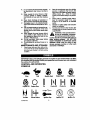
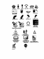
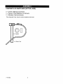
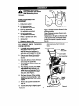
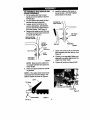

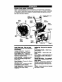

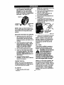
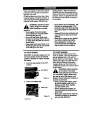
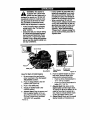
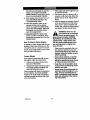

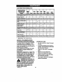
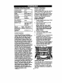


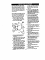
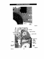

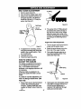
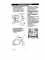
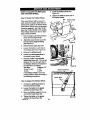
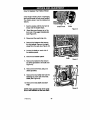
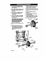
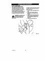

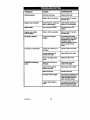


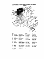
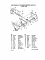

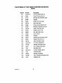
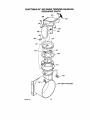
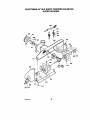

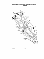

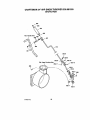
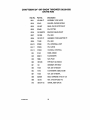

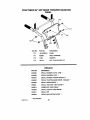
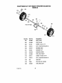

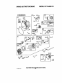
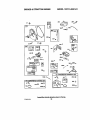
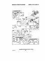
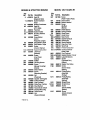

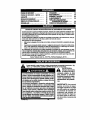
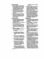
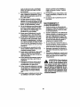


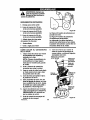

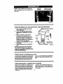
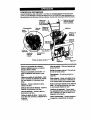
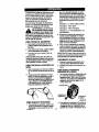


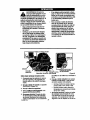

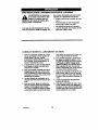
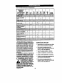

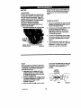
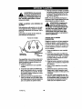
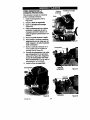


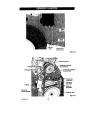

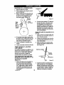


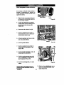
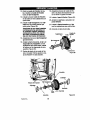
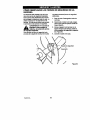
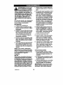
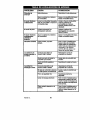


![CRRFTSMRN °] - at snowblowerguide.com](http://vs1.manualzilla.com/store/data/006202620_1-711fb90bb2c79d693479b4ac54c29ad0-150x150.png)