Download Yamaha XT660X Service manual

Transcript
2007
XT660R(W)
XT660X(W)
SUPPLEMENTARY
SERVICE MANUAL
5VK-F8197-E2
FOREWORD
This Supplementary Service Manual has been prepared to introduce new service and data for the
XT660R(W)/XT660X(W) 2007. For complete service information procedures it is necessary to use
this Supplementary Service Manual together with the following manual.
XT660R(S)/XT660X(S) 2004 SERVICE MANUAL: 5VK1-AE1
XT660R(W)/XT660X(W) 2007
SUPPLEMENTARY
SERVICE MANUAL
©2006 by MBK Industrie
First edition, July 2006
All rights reserved.
Any reproduction or unauthorized use
without the written permission of
MBK Industrie
is expressly prohibited.
EAS00002
NOTICE
This manual was produced by MBK Industrie primarily for use by Yamaha dealers and their qualified mechanics. It is not possible to include all the knowledge of a mechanic in one manual. Therefore, anyone who uses this book to perform maintenance and repairs on Yamaha vehicles should
have a basic understanding of mechanics and the techniques to repair these types of vehicles.
Repair and maintenance work attempted by anyone without this knowledge is likely to render the
vehicle unsafe and unfit for use.
Yamaha is continually striving to improve all its models. Modifications and significant changes in
specifications or procedures will be forwarded to all authorized Yamaha dealers and will appear in
future editions of this manual where applicable.
NOTE:
Designs and specifications are subject to change without notice.
_
EAS00004
IMPORTANT MANUAL INFORMATION
Particularly important information is distinguished in this manual by the following.
The Safety Alert Symbol means ATTENTION! BECOME ALERT! YOUR
SAFETY IS INVOLVED!
WARNING
CAUTION:
NOTE:
Failure to follow WARNING instructions could result in severe injury or death
to the motorcycle operator, a bystander or a person checking or repairing
the motorcycle.
A CAUTION indicates special precautions that must be taken to avoid damage to the motorcycle.
A NOTE provides key information to make procedures easier or clearer.
EAS00007
HOW TO USE THIS MANUAL
This manual is intended as a handy, easy-to-read reference book for the mechanic. Comprehensive
explanations of all installation, removal, disassembly, assembly, repair and check procedures are
laid out with the individual steps in sequential order.
1 The manual is divided into chapters. An abbreviation and symbol in the upper right corner of
each page indicate the current chapter.
Refer to “SYMBOLS”.
2 Each chapter is divided into sections. The current section title is shown at the top of each page,
except in Chapter 3 (“PERIODIC CHECKS AND ADJUSTMENTS”), where the sub-section
title(s) appears.
3 Sub-section titles appear in smaller print than the section title.
4 To help identify parts and clarify procedure steps, there are exploded diagrams at the start of
each removal and disassembly section.
5 Numbers are given in the order of the jobs in the exploded diagram. A circled number indicates a
disassembly step.
6 Symbols indicate parts to be lubricated or replaced.
Refer to “SYMBOLS”.
7 A job instruction chart accompanies the exploded diagram, providing the order of jobs, names of
parts, notes in jobs, etc.
8 Jobs requiring more information (such as special tools and technical data) are described sequentially.
1
EAS00008
2
GEN
INFO
SYMBOLS
The following symbols are not relevant to
every vehicle.
Symbols 1 to 9 indicate the subject of each
chapter.
SPEC
3
4
CHK
ADJ
1 General information
2 Specifications
3 Periodic checks and adjustments
4 Chassis
5 Engine
6 Cooling system
7 Fuel injection system
8 Electrical system
9 Troubleshooting
CHAS
5
6
ENG
COOL
7
8
FI
–
ELEC
9
Symbols 0 to G indicate the following.
0
0 Serviceable with engine mounted
A Filling fluid
B Lubricant
C Special tool
D Tightening torque
E Wear limit, clearance
F Engine speed
G Electrical data
TRBL
SHTG
A
B
C
D
+
T.
R.
E
F
G
H
I
J
G
E
K
M
L
B
M
M
LS
N
Symbols H to M in the exploded diagrams
indicate the types of lubricants and lubrication
points.
Symbols N to O in the exploded diagrams
indicate the following.
O
LT
H Engine oil
I Gear oil
J Molybdenum-disulfide oil
K Wheel-bearing grease
L Lithium-soap-based grease
M Molybdenum-disulfide grease
New
N Apply locking agent (LOCTITE®)
O Replace the part
CONTENTS
SPECIFICATIONS .............................................................................................. 1
GENERAL SPECIFICATIONS ..................................................................... 1
ENGINE SPECIFICATIONS......................................................................... 2
CHASSIS SPECIFICATIONS....................................................................... 6
ELECTRICAL SPECIFICATIONS ................................................................ 8
TIGHTENING TORQUE ............................................................................... 8
ENGINE TIGHTENING TORQUES ....................................................... 8
CHASSIS TIGHTENING TORQUES ..................................................... 8
CABLE ROUTING ........................................................................................ 9
PERIODIC CHECKS AND ADJUSTMENTS.................................................... 22
COWLING AND COVER ............................................................................ 22
COVER ................................................................................................ 22
COWLING ............................................................................................ 23
FUEL TANK................................................................................................ 24
CHASSIS.................................................................................................... 26
ADJUSTING THE DRIVE CHAIN SLACK............................................ 26
CHECKING THE TIRES ...................................................................... 28
CHASSIS .......................................................................................................... 32
REAR WHEEL, BRAKE DISC, AND REAR WHEEL SPROCKET............. 32
REAR WHEEL ..................................................................................... 32
REMOVING THE REAR WHEEL (XT660R) ........................................ 34
REMOVING THE REAR WHEEL (XT660X) ........................................ 35
INSTALLING THE REAR WHEEL (XT660R)....................................... 35
INSTALLING THE REAR WHEEL (XT660X)....................................... 36
SWINGARM AND DRIVE CHAIN............................................................... 38
ENGINE ............................................................................................................ 41
ENGINE REMOVAL ................................................................................... 41
EXHAUST PIPES AND MUFFLERS.................................................... 41
CYLINDER HEAD ...................................................................................... 42
CYLINDER AND PISTON .......................................................................... 44
COOLING SYSTEM.......................................................................................... 46
RADIATOR ................................................................................................. 46
FUEL INJECTION SYSTEM............................................................................. 48
FUEL INJECTION SYSTEM....................................................................... 48
WIRING DIAGRAM .............................................................................. 49
FAIL-SAFE ACTION TABLE ................................................................ 50
DIAGNOSTIC MODE ........................................................................... 52
TROUBLESHOOTING DETAILS ......................................................... 58
ELECTRICAL SYSTEM.................................................................................... 71
ELECTRICAL COMPONENTS................................................................... 71
XT660R(W)/XT660X(W) 2007 WIRING DIAGRAM
GENERAL SPECIFICATIONS
SPEC
SPECIFICATIONS
GENERAL SPECIFICATIONS
Item
Model code
Dimensions
Overall length
Overall width
Overall height
Seat height
Wheelbase
Minimum ground clearance
Minimum turning radius
Standard
Limit
XT660R: 5VK8 (Europe)
5VK9 (AUS)
XT660X: 10S1 (Europe)
10S2 (AUS)
-------------
2,240 mm (88.2 in) (XT660R)
2,175 mm (85.6 in) (XT660X)
845 mm (33.3 in) (XT660R)
860 mm (33.9 in) (XT660X)
1,230 mm (48.4 in) (XT660R)
1,170 mm (46.1 in) (XT660X)
865 mm (34.1 in) (XT660R)
875 mm (34.4 in) (XT660X)
1,505 mm (59.3 in) (XT660R)
1,490 mm (58.7 in) (XT660X)
210 mm (8.27 in) (XT660R)
205 mm (8.07 in) (XT660X)
2,400 mm (94.5 in)
----------------------------------------
–1–
ENGINE SPECIFICATIONS
SPEC
ENGINE SPECIFICATIONS
Item
Engine
Engine type
Displacement
Cylinder arrangement
Bore × stroke
Compression ratio
Engine idling speed
Water temperature
Oil temperature
Standard compression pressure
(at sea level)
Engine oil
Lubrication system
Recommended oil
-20 -10 0 10 20 30 40 50 ˚C
SAE 10W-30
Standard
Limit
Liquid-cooled, 4-stroke, SOHC
660 cm3
Forward-inclined single cylinder
100.0 × 84.0 mm (3.94 × 3.31 in)
10.00 : 1
1,400 ~ 1,500 r/min
80 °C (176 °F)
55 ~ 65 °C (131 ~ 149 °F)
650 kPa (6.5 kg/cm2, 92.4 psi)
at 800 r/min
----------------------------
Dry sump
----
SAE 10W30, SAE 10W-40, SAE 15W40,
SAE 20W40 or SAE 20W-50
Refer to the chart for engine oil grade.
----
API service SG type or higher, JASO
standard MA
----
2.90 L (2.55 Imp qt, 3.07 US qt)
2.50 L (2.20 Imp qt, 2.64 US qt)
2.60 L (2.29 Imp qt, 2.75 US qt)
----------
SAE 10W-40
SAE 15W-40
SAE 20W-40
SAE 20W-50
Recommended engine oil grade
Quantity
Total amount
Periodic oil change
With oil filter replacement
Oil pump
Oil pump type
Inner-rotor-to-outer-rotor-tip clearance
Outer-rotor-to-oil-pump-housing
clearance
Oil-pump-housing-to-inner-rotor-andouter-rotor clearance
Trochoid
0.03 ~ 0.08 mm (0.0012 ~ 0.0031 in)
0.09 ~ 0.15 mm (0.0035 ~ 0.0059 in)
0.03 ~ 0.08 mm (0.0012 ~ 0.0031 in)
–2–
---0.16 mm
(0.0063 in)
0.22 mm
(0.0087 in)
0.15 mm
(0.0059 in)
ENGINE SPECIFICATIONS
Item
Standard
Camshaft
Drive system
Intake camshaft lobe dimensions
Chain drive (left)
SPEC
Limit
----
A
B
Measurement A
43.488 ~ 43.588 mm (1.7121 ~ 1.7161 in) 43.388 mm
(1.7082 in)
36.959 ~ 37.059 mm (1.4551 ~ 1.4590 in) 36.859 mm
(1.4511 in)
Measurement B
Exhaust camshaft lobe dimensions
A
B
Measurement A
Measurement B
Valve timing
Intake - open (B.T.D.C.)
Intake - closed (A.B.D.C.)
Exhaust - open (B.B.D.C.)
Exhaust - closed (A.T.D.C.)
Overlap angle “A”
Maximum camshaft runout
Timing chain
Model/number of links
Tensioning system
43.129 ~ 43.229 mm (1.6980 ~ 1.7019 in) 43.029 mm
(1.6941 in)
37.007 ~ 37.107 mm (1.4570 ~ 1.4609 in) 36.907 mm
(1.4530 in)
25°
55°
60°
20°
45°
----
---------------0.040 mm
(0.0016 in)
98XRH2010/126
Automatic
–3–
-------
ENGINE SPECIFICATIONS
Item
SPEC
Standard
Piston
Piston-to-cylinder clearance
Limit
0.030 ~ 0.055 mm (0.0012 ~ 0.0022 in)
0.13 mm
(0.0051 in)
99.955 ~ 99.970 mm (3.9352 ~ 3.9358 in)
----
Diameter D
H
D
Height H
Piston pin bore (in the piston)
Diameter
10.0 mm (0.39 in)
----
23.004 ~ 23.015 mm (0.9057 ~ 0.9061 in) 23.045 mm
(0.9073 in)
0.50 mm (0.0197 in)
---Intake side
----
Offset
Offset direction
Piston pin
Outside diameter
22.991 ~ 23.000 (0.9052 ~ 0.9055 in)
Piston-pin-to-piston-pin-bore clearance
Piston rings
Top ring
0.004 ~ 0.024 mm (0.0002 ~ 0.0009 in)
22.971 mm
(0.9044 in)
0.074 mm
(0.0029 in)
B
T
Ring type
Dimensions (B × T)
End gap (installed)
Barrel
1.20 × 3.80 mm (0.047 × 0.150 in)
0.20 ~ 0.35 mm (0.0079 ~ 0.0138 in)
Ring side clearance
0.030 ~ 0.080 mm (0.0012 ~ 0.0031 in)
------0.60 mm
(0.0236 in)
0.13 mm
(0.0051 in)
2nd ring
B
T
Ring type
Dimensions (B × T)
End gap (installed)
Taper
1.20 × 4.00 mm (0.047 × 0.157 in)
0.35 ~ 0.50 mm (0.0138 ~ 0.0197 in)
Ring side clearance
0.030 ~ 0.070 mm (0.0012 ~ 0.0028 in)
–4–
------0.85 mm
(0.0335 in)
0.13 mm
(0.0051 in)
ENGINE SPECIFICATIONS
Item
SPEC
Standard
Limit
Oil ring
B
T
Dimensions (B × T)
End gap (installed)
Ring side clearance
Throttle body
Model/manufacturer × quantity
Intake vacuum pressure
Throttle cable free play (at the flange
of the throttle grip)
ID mark
Throttle valve size
2.50 × 3.40 mm (0.098 × 0.134 in)
0.20 ~ 0.70 mm (0.0079 ~ 0.0276 in)
0.060 ~ 0.150 mm (0.0024 ~ 0.0059 in)
----------
44EHS/MIKUNI × 1
37.6 ~ 40.2 kPa
(282 ~ 302 mmHg, 11.1 ~ 11.9 inHg)
3.0 ~ 5.0 mm (0.12 in ~ 0.20 mm)
-------
5VK8 10
#50
-------
–5–
----
CHASSIS SPECIFICATIONS
SPEC
CHASSIS SPECIFICATIONS
Item
Rear wheel
Wheel type
Rim
Size
Material
Wheel travel
Standard
Spoke wheel
----
17M/C × MT2.75 (XT660R)
17M/C × MT4.25 (XT660X)
Aluminum
200.0 mm (7.87 in) (XT660R)
191.0 mm (7.52 in) (XT660X)
----------------
Wheel runout
Maximum radial wheel runout
----
Maximum lateral wheel runout
----
Wheel axle bending limit
Front tire
Tire type
Size
Model/manufacturer
Tire pressure (cold)
0 ~ 90 kg (0 ~ 198 lb)
90 (198 lb) ~ Maximum load*
Off-road riding
Minimum tire tread depth
Limit
2.0 mm
(0.08 in)
2.0 mm
(0.08 in)
0.25 mm
(0.01 in)
----
With tube
90/90-21M/C 54S, 90/90-21M/C 54T
(XT660R)
120/70R 17M/C 58 H, 120/70ZR 17M/C
58W, 120/70ZR 17M/C 58W (XT660X)
TOURANCE FRONT/METZELER,
SIRAC/MICHELIN (XT660R)
DRAGON/PIRELLI, SPORTEC M1/
METZELER, RADIAL PILOT SPORT/
MICHELIN (XT660X)
-------
200 kPa (2.00 kgf/cm, 29 psi) (XT660R)
210 kPa (2.10 kgf/cm, 30 psi) (XT660X)
200 kPa (2.00 kgf/cm, 29 psi) (XT660R)
220 kPa (2.20 kgf/cm, 31 psi) (XT660X)
* Load is the total weight of the cargo,
rider, passenger and accessories.
200 kPa (2.00 kgf/cm, 29 psi) (XT660R)
----
-------------
–6–
----------
---1.6 mm
(0.063 in)
CHASSIS SPECIFICATIONS
Item
Rear tire
Tire type
Size
Model/manufacturer
Tire pressure (cold)
0 ~ 90 kg (0 ~ 198 lb)
90 (198 lb) ~ Maximum load*
Off-road riding
Minimum tire tread depth
SPEC
Standard
Limit
With tube
130/80-17M/C 65S, 130/80-17M/C 65T
(XT660R)
160/60R 17M/C 69H, 160/60ZR 17M/C
69W, 160/60ZR 17M/C 69W (XT660X)
TOURANCE/METZELER, SIRAC A/
MICHELIN (XT660R)
DRAGON/PIRELLI, SPORTEC M1/
METZELER, RADIAL PILOT SPORT/
MICHELIN (XT660X)
-------
200 kPa (2.00 kgf/cm, 29 psi) (XT660R)
210 kPa (2.10 kgf/cm, 30 psi) (XT660X)
225 kPa (2.25 kgf/cm, 33 psi) (XT660R)
230 kPa (2.30 kgf/cm, 33 psi) (XT660X)
* Load is the total weight of the cargo,
rider, passenger and accessories.
200 kPa (2.00 kgf/cm, 29 psi) (XT660R)
----
-------------
–7–
----------
---1.6 mm
(0.063 in)
ELECTRICAL SPECIFICATIONS/
TIGHTENING TORQUE
SPEC
ELECTRICAL SPECIFICATIONS
Item
Standard
System voltage
Ignition system
Ignition system type
Ignition timing
Advancer type
Crankshaft position senor resistance/
color
Transistorized coil ignition unit
model/manufacturer
Limit
12 V
----
Transistorized coil ignition (digital)
5.0° BTDC at 1,450 r/min
Electric
192 ~ 288 Ω at 20 °C (68 °F)
blue/yellow–green/white
TBDF36/DENSO
----------------
TIGHTENING TORQUE
ENGINE TIGHTENING TORQUES
Part to be tightened
O2 sensor
O2 sensor protector
Part name
—
Bolt
Thread
Q’ty
size
M18
M6
1
2
Tightening torque
Nm m · kg ft · lb
45
10
4.5
1.0
Remarks
32
7.2
CHASSIS TIGHTENING TORQUES
Thread
size
Part to be tightened
Engine mounting:
Engine upper bracket and frame
Engine front bracket and frame
Engine front bracket and engine
Engine and frame
M10
M10
M10
M10
–8–
Tightening torque
Nm m · kg ft · lb
65
65
65
65
6.5
6.5
6.5
6.5
47
47
47
47
Remarks
CABLE ROUTING
SPEC
EAS00035
CABLE ROUTING
1 Front turn signal light lead (right)
2 Meter assembly lead
3 Auxiliary light lead
4 Front turn signal light lead (left)
5 Headlight lead
6 Sub-wire harness
È Fasten the sub-wire harness and meter assembly lead with a plastic band. Fasten the sub-wire
harness at the white tape. Face the end of the
plastic band forward.
É Make sure that there is no slack in the meter
assembly lead between the meter assembly and
the plastic band. The rubber boot on the meter
assembly can be bent as shown.
–9–
CABLE ROUTING
Ê Place the slack of the left and right front turn signal light leads between the headlight assembly
and front cowling assembly.
Ë Fasten the left and right front turn signal light
leads to the headlight stay with a plastic locking
tie, and then cut off the excess end of tie.
Ì Pass the left and right front turn signal light leads
in front of the headlight stay.
SPEC
Í Only the left side is shown in this illustration.
Route the right front turn signal light lead in the
same way.
Î Pass the left and right front turn signal light leads
between the headlight stay and front fork protector.
Ï XT660R
Ð 0 ~ 5 mm (0 ~ 0.20 in) for both left and right
sides
Ñ XT660X
– 10 –
CABLE ROUTING
SPEC
È Fasten the wire harness and negative battery
lead to the frame with a plastic locking tie.
É Fasten the wire harness, negative battery lead,
and rear brake light switch lead to the frame with
a plastic locking tie.
Ê Fasten the rear brake light switch lead to the
frame with a plastic locking tie.
Ë Fasten the wire harness to the frame at the
white tape with a plastic locking tie.
1 Rear brake light switch lead
2 Negative battery lead
3 Lean angle cut-off switch lead
4 Throttle position sensor lead
5 Coolant temperature sensor lead
6 Turn signal/hazard relay
7 Headlight relay
8 Radiator fan motor relay
9 Relay unit
È
1
9
8
7
6
Í
Ì
Ê
– 11 –
É
Ê
2
Ë
3
4
5
CABLE ROUTING
SPEC
Ì Route the negative battery lead behind the lean
angle cut-off switch bracket.
Í Route the rear brake light switch lead between
the air filter case and the frame.
È
1
9
8
7
6
Í
Ì
Ê
– 12 –
É
Ê
2
Ë
3
4
5
CABLE ROUTING
1 Neutral switch connector
2 Crankshaft position sensor
coupler
3 A.C. magneto coupler
4 Speed sensor lead
5 Intake air temperature sensor
lead
6 ECU lead
7 Starter motor lead
8 Sidestand switch lead
9 Speed sensor
0 A.C. magneto lead
A Oil tank breather hose
B Oil delivery hose 2
C Radiator fan motor lead
D Throttle cable
E Headlight lead
F Meter assembly lead
G Left handlebar switch lead
H Right handlebar switch lead
I Front brake light switch lead
J Clutch switch lead
SPEC
K Immobilizer unit lead
L Clutch cable
M Main switch lead
N O2 sensor lead
O Air-filter-to-air-cut-off-valve
hose
P Wire harness
H
G
I
G
H
E
J
F
E
M
D
I J
K
L
D F
C
B
A-A
B-B
N
D
C-C
P
È
É
A
8
D
B
Ê
B
C
A
A
O
E-E
D
F-F
Ë 1 2 3 4 Ì 567
B
E
C
E
Ó
D
G
C
Ò
Ñ
Ô
B
A
Ð
Ï
N
F
F
G
0
9
– 13 –
8
Î Í
CABLE ROUTING
SPEC
É Fasten the left handlebar switch lead, right handlebar switch lead, headlight lead, meter assembly lead, front brake light switch lead, clutch
switch lead, radiator fan motor lead, and throttle
cables with a plastic band. To fasten the leads
and cables, connect the couplers, and then turn
the handlebar completely to the right.
Ê Route the oil tank breather hose on the outside
of the throttle cables.
È Fasten the left handlebar switch lead, right handlebar switch lead, headlight lead, meter assembly lead, front brake light switch lead, and clutch
switch lead to the frame with a plastic locking tie.
To fasten the leads, connect the couplers, and
then turn the handlebar completely to the right.
H
G
I
G
H
E
J
F
E
M
D
I J
K
L
D F
C
B
A-A
B-B
N
D
C-C
P
È
É
A
8
D
B
Ê
B
C
A
A
O
E-E
D
F-F
Ë 1 2 3 4 Ì 567
B
E
C
E
Ó
D
G
C
Ò
Ñ
Ô
B
A
Ð
Ï
N
F
F
G
0
9
– 14 –
8
Î Í
CABLE ROUTING
SPEC
Ï Fasten the neutral switch lead, crankshaft position sensor lead, sidestand switch lead, speed
sensor lead, starter motor lead, and A.C. magneto lead with a plastic band.
Ð Fasten the neutral switch lead, crankshaft position sensor lead, sidestand switch lead, speed
sensor lead, and starter motor lead with a plastic
band.
Ñ Fasten the air-filter-to-air-cut-off-valve hose, oil
tank breather hose, and oil delivery hose 2 with
a plastic clamp.
Ë Fasten the wire harness to the frame at the
white tape with a plastic locking tie.
Ì Fasten the starter motor lead to the frame with a
plastic locking tie.
Í Fasten the sidestand switch lead to the frame
with a plastic locking tie.
Î Route the sidestand switch lead at the front end
of the left side heel plate.
H
G
I
G
H
E
J
F
E
M
D
I J
K
L
D F
C
B
A-A
B-B
N
D
C-C
P
È
É
A
8
D
B
Ê
B
C
A
A
O
E-E
D
F-F
Ë 1 2 3 4 Ì 567
B
E
C
E
Ó
D
G
C
Ò
Ñ
Ô
B
A
Ð
Ï
N
F
F
G
0
9
– 15 –
8
Î Í
CABLE ROUTING
Ò Fasten the wire harness, air-filter-to-air-cut-offvalve hose, and oil delivery hose 2 with a plastic
clamp.
Ó Fasten the left handlebar switch lead, right handlebar switch lead, headlight lead, meter assembly lead, front brake light switch lead, and clutch
switch lead with a plastic band.
SPEC
Turn the handlebar completely to the right, and
then fasten the left handlebar switch lead, right
handlebar switch lead, headlight lead, meter
assembly lead, front brake light switch lead, and
clutch switch lead next to the steering head pipe
with the plastic band. Be sure to connect the
couplers before fastening the leads.
Ô Fasten the O2 sensor lead and air-filter-to-aircut-off-valve hose with a holder as shown in the
illustration.
H
G
I
G
H
E
J
F
E
M
D
I J
K
L
D F
C
B
A-A
B-B
N
D
C-C
P
È
É
A
8
D
B
Ê
B
C
A
A
O
E-E
D
F-F
Ë 1 2 3 4 Ì 567
B
E
C
E
Ó
D
G
C
Ò
Ñ
Ô
B
A
Ð
Ï
N
F
F
G
0
9
– 16 –
8
Î Í
CABLE ROUTING
SPEC
È 0 ~ 10 mm (0 ~ 0.39 in)
É 30 ~ 40 mm (1.18 ~ 1.57 in)
Ê 5 ~ 15 mm (0.20 ~ 0.59 in)
Ë Fasten the wire harness to the frame with a plastic locking tie.
Ì To the fuel tank
Í 0 ~ 5 mm (0 ~ 0.20 in)
Î Europe, ZA
1 Immobilizer unit coupler
2 Intake air temperature sensor
3 Fuel injector lead
4 Fuel pump lead
5 Fuel sender lead
6 Oil tank breather hose
Î
È
È
1
1
6
Ê
É
A
Ê
A
Ë
Ë
5
2
Ì
3
4
Í
Í
– 17 –
CABLE ROUTING
SPEC
È Fasten the tail/brake light lead with two plastic
locking ties so that the coupler is positioned to
the inside of where the relays (turn signal/hazard
relay, headlight relay, radiator fan motor relay,
and relay unit) branch off from the wire harness.
É To relays (turn signal/hazard relay, headlight
relay, radiator fan motor relay, and relay unit)
1 Battery
2 Negative battery lead
3 Tail/brake light coupler
4 Rear turn signal light connector
5 Seat lock cable
6 Anti-theft alarm coupler
7 Fuse box 2
8 Positive battery lead
9 Fuse box 1
0 Rear fender
A Rear fender cover
È
É
Ï
9
8
Ê
7
1
2
6
5
Î
Í
A
3
A
Ì
0
4
Ë
A
Ð
A-A
– 18 –
CABLE ROUTING
Ê Fasten the wire harness with plastic locking ties,
making sure to install the ties around the taped
sections of the harness. Do not install the plastic
locking ties around the sections of the leads that
are not covered by the tape and do not fasten
the negative battery lead coupler.
Ë Fasten the rear turn signal light leads and tail/
brake light lead with a lead holder.
Ì Connect the couplers so that they are not
pinched between the rear fender and rear fender
cover.
SPEC
Í Fasten the wire harness to the frame with a plastic locking tie.
Î 0 ~ 5 mm (0 ~ 0.20 in)
Ï 0 ~ 10 mm (0 ~ 0.39 in)
Ð The tail/brake light coupler and the rear turn signal light lead should not be lower than the line
shown in the illustration.
È
É
Ï
9
8
Ê
7
1
2
6
5
Î
Í
A
3
A
Ì
0
4
Ë
A
Ð
A-A
– 19 –
CABLE ROUTING
XT660R
1 Brake fluid reservoir
2 Brake fluid reservoir hose
3 Rear brake light switch
4 Rear brake master cylinder
5 Rear brake hose
6 Rear brake caliper
SPEC
È When installing the brake hose onto the brake
master cylinder, make sure that the brake pipe
touches the brake master cylinder as shown.
É Fasten the rear brake hose with the brake hose
holder.
Ê When installing the brake hose onto the brake
caliper, make sure that the brake pipe touches
the brake caliper as shown.
– 20 –
CABLE ROUTING
È When installing the brake hose onto the brake
master cylinder, make sure that the brake pipe
touches the brake master cylinder as shown.
É Fasten the rear brake hose with the brake hose
holder.
Ê When installing the brake hose onto the brake
caliper, make sure that the brake pipe touches
the brake caliper as shown.
XT660X
1 Brake fluid reservoir
2 Brake fluid reservoir hose
3 Rear brake light switch
4 Rear brake master cylinder
5 Rear brake hose
6 Rear brake caliper
5
SPEC
È
É
5
Ê
C
B
A
1
A
6
2
C
3
B
B
B
B
4
5
– 21 –
COWLING AND COVER
CHK
ADJ
PERIODIC CHECKS AND ADJUSTMENTS
COWLING AND COVER
COVER
T.
R.
7 Nm (0.7 m • kg, 5.1 ft • Ib)
1
3
4
5
4
T.
R.
23 Nm (2.3 m • kg, 17 ft • Ib)
2
T.
R.
Order
1
2
3
4
5
Job/Part
Removing the cover (XT660X)
Seat
Left side panel
Right side panel
Grab bar
Rear cover
Q’ty
7 Nm (0.7 m • kg, 5.1 ft • Ib)
Remarks
Remove the parts in the order listed.
1
1
1
2
1
For installation, reverse the removal procedure.
– 22 –
COWLING AND COVER
CHK
ADJ
COWLING
5
3
4
2
1
T.
R.
T.
R.
Order
1
2
3
4
5
8 Nm (0.8 m • kg, 5.8 ft • Ib)
7 Nm (0.7 m • kg, 5.1 ft • Ib)
Job/Part
Removing the cowling (XT660X)
Seat/side panels (left and right)
Fuel tank
Front fender
Front fork protector
Meter assembly coupler
Sub-wire harness coupler
Front cowling assembly
Q’ty
1
1
2
1
1
Remarks
Remove the parts in the order listed.
Refer to “COWLING AND COVER”.
Refer to “FUEL TANK”.
Disconnect.
Disconnect.
For installation, reverse the removal procedure.
– 23 –
FUEL TANK
CHK
ADJ
EAS00040
FUEL TANK
T.
9
R.
10 Nm (1.0 m • kg, 7.2 ft • Ib)
4
5
3
10
8
6
2
7
1
Order
1
2
3
4
5
6
7
8
Job/Part
Removing the fuel tank (XT660X)
Seat/side panels (left and right)
Fuel
Fuel tank left side cover
Fuel tank right side cover
Intake air guide
Fuel tank plate
Damper 1
Fuel pump coupler
Fuel sender coupler
Fuel hose
9
Fuel tank
Q’ty
1
1
1
1
1
1
1
1
1
– 24 –
Remarks
Remove the parts in the order listed.
Refer to “COWLING AND COVER”.
Drain.
Disconnect.
Disconnect.
Refer to “REMOVING THE FUEL TANK”
and “INSTALLING THE FUEL HOSE” in
chapter 3. (Manual No.: 5VK1-AE1)
FUEL TANK
T.
9
CHK
ADJ
R.
10 Nm (1.0 m • kg, 7.2 ft • Ib)
4
5
3
10
8
6
2
7
1
Order
10
Job/Part
Damper 2
Q’ty
1
Remarks
For installation, reverse the removal procedure.
– 25 –
ADJUSTING THE DRIVE CHAIN SLACK
CHK
ADJ
EAS00140
CHASSIS
ADJUSTING THE DRIVE CHAIN SLACK
NOTE:
The drive chain slack must be checked at the
tightest point on the chain.
_
CAUTION:
_
A drive chain that is too tight will overload
the engine and other vital parts, and one
that is too loose can skip and damage the
swingarm or cause an accident. Therefore,
keep the drive chain slack within the specified limits.
1. Stand the motorcycle on a level surface.
WARNING
_
Securely support the motorcycle so that
there is no danger of it falling over.
NOTE:
Place the motorcycle on a suitable stand so
that the rear wheel is elevated.
_
2. Spin the rear wheel several times and find
the tightest position of the drive chain.
3. Check:
• drive chain slack a
Out of specification → Adjust.
Drive chain slack
40.0 ~ 55.0 mm (1.57 ~ 2.17 in)
– 26 –
ADJUSTING THE DRIVE CHAIN SLACK
CHK
ADJ
4. Adjust:
• drive chain slack
È
▼▼▼▼▼▼▼▼▼▼▼▼▼▼▼▼▼▼▼▼▼▼▼▼▼▼▼▼▼▼▼▼
a. Loosen the wheel axle nut 1.
b. Loosen both locknuts 2.
c. Turn both adjusting nuts 3 or both adjusting bolt 4 in direction a or b until the
specified drive chain slack is obtained.
É
Direction a
Drive chain is tightened.
Direction b
Drive chain is loosened.
NOTE:
To maintain the proper wheel alignment, adjust
both sides evenly.
_
a
2
1
b
4
d. Tighten both locknuts to the specified
torque.
T.
Locknut
16 Nm (1.6 m · kg, 11 ft · lb)
R.
e. Tighten the wheel axle nut to the specified
torque.
T.
Wheel axle nut
105 Nm (10.5 m · kg, 75 ft · lb)
R.
▲▲▲▲▲▲▲▲▲▲▲▲▲▲▲▲▲▲▲▲▲▲▲▲▲▲▲▲▲▲▲▲
È XT660R
É XT660X
– 27 –
CHECKING THE TIRES
CHK
ADJ
EAS00166
CHECKING THE TIRES
The following procedure applies to both of the
tires.
1. Check:
• tire pressure
Out of specification → Regulate.
WARNING
_
• The tire pressure should only be checked
and regulated when the tire temperature
equals the ambient air temperature.
• The tire pressure and the suspension
must be adjusted according to the total
weight (including cargo, rider, passenger
and accessories) and the anticipated
riding speed.
• Operation of an overloaded motorcycle
could cause tire damage, an accident or
an injury.
NEVER OVERLOAD THE MOTORCYCLE.
XT660R
Basic weight
(with oil and a
full fuel tank)
181.0 kg (399 lb)
Maximum
load*
186.0 kg (410 lb)
Cold tire
pressure
– 28 –
Front
Rear
Up to 90 kg
load*
200 kPa
200 kPa
(2.00 kgf/cm2, (2.00 kgf/cm2,
29 psi)
29 psi)
90 kg ~ maximum load*
200 kPa
225 kPa
2
(2.00 kgf/cm , (2.25 kgf/cm2,
29 psi)
33 psi)
Off-road
riding
200 kPa
200 kPa
2
(2.00 kgf/cm , (2.00 kgf/cm2,
29 psi)
29 psi)
CHECKING THE TIRES
CHK
ADJ
XT660X
Basic weight
(with oil and a
full fuel tank)
186.0 kg (410 lb)
Maximum
load*
186.0 kg (410 lb)
Cold tire
pressure
Front
Rear
Up to 90 kg
load*
210 kPa
210 kPa
(2.10 kgf/cm2, (2.10 kgf/cm2,
30 psi)
30 psi)
90 kg ~ maximum load*
230 kPa
220 kPa
(2.20 kgf/cm2, (2.30 kgf/cm2,
31 psi)
33 psi)
* Total weight of rider, passenger, cargo and
accessories
WARNING
_
It is dangerous to ride with a worn-out tire.
When the tire tread reaches the wear limit,
replace the tire immediately.
2. Check:
• tire surfaces
Damage/wear → Replace the tire.
Minimum tire tread depth
1.6 mm (0.063 in)
1 Tire tread depth
2 Sidewall
3 Wear indicator
WARNING
_
• Do not use a tubeless tire on a wheel
designed only for tube tires to avoid tire
failure and personal injury from sudden
deflation.
• When using tube tires, be sure to install
the correct tube.
• Always replace a new tube tire and a new
tube as a set.
• To avoid pinching the tube, make sure the
wheel rim band and tube are centered in
the wheel groove.
– 29 –
CHECKING THE TIRES
È
É
CHK
ADJ
• Patching a punctured tube is not recommended. If it is absolutely necessary to
do so, use great care and replace the tube
as soon as possible with a good quality
replacement.
È Tire
É Wheel
Tube wheel
Tube tire only
Tubeless wheel
Tube or tubeless
tire
• After extensive tests, the tires listed
below have been approved by Yamaha
Motor Co., Ltd. for this model. The front
and rear tires should always be by the
same manufacturer and of the same
design. No guarantee concerning handling characteristics can be given if a tire
combination other than one approved by
Yamaha is used on this motorcycle.
Front tire (XT660R)
Manufacturer
Model
Size
METZELER
TOURANCE
FRONT
90/9021M/C 54S
MICHELIN
SIRAC
90/9021M/C 54T
Manufacturer
Model
Size
METZELER
TOURANCE
130/8017M/C 65S
MICHELIN
SIRAC A
130/8017M/C 65T
Manufacturer
Model
Size
PIRELLI
DRAGON
120/70R
17M/C 58H
METZELER
SPORTEC
M1
120/70ZR
17M/C 58W
MICHELIN
RADIAL
PILOT
SPORT
120/70ZR
17M/C 58W
Rear tire (XT660R)
Front tire (XT660X)
– 30 –
CHECKING THE TIRES
CHK
ADJ
Rear tire (XT660X)
Manufacturer
Model
Size
PIRELLI
DRAGON
160/60R
17M/C 69H
METZELER
SPORTEC
M1
160/60ZR
17M/C 69W
MICHELIN
RADIAL
PILOT
SPORT
160/60ZR
17M/C 69W
WARNING
_
New tires have a relatively low grip on the
road surface until they have been slightly
worn. Therefore, approximately 100 km
should be traveled at normal speed before
any high-speed riding is done.
NOTE:
For tires with a direction of rotation mark 1:
• Install the tire with the mark pointing in the
direction of wheel rotation.
• Align the mark 2 with the valve installation
point.
_
– 31 –
REAR WHEEL, BRAKE DISC, AND REAR WHEEL
SPROCKET
CHAS
CHASSIS
REAR WHEEL, BRAKE DISC, AND REAR WHEEL SPROCKET
REAR WHEEL
8
11
T.
10
R.
105 Nm (10.5 m • kg, 75 ft • lb)
T.
R.
9
16 Nm (1.6 m • kg, 11 ft • Ib)
13
4
5
6
3
12
4
3
LS
7
2
1
T.
R.
Order
1
2
3
4
5
6
7
8
9
10
11
Job/Part
Removing the rear wheel (XT660X)
Stabilizer
Chain cover
Locknut
Adjusting bolt
Wheel axle nut
Washer
Wheel axle
Rear wheel
Collar (left)
Collar (right)
Rear brake caliper
Q’ty
1
1
2
2
1
1
1
1
1
1
1
– 32 –
7 Nm (0.7 m • kg, 5.1 ft • Ib)
Remarks
Remove the parts in the order listed.
Refer to “REMOVING THE REAR
WHEEL (XT660X)” and “INSTALLING
THE REAR WHEEL (XT660X)”.
Refer to “REMOVING THE REAR
WHEEL (XT660X)”.
REAR WHEEL, BRAKE DISC, AND REAR WHEEL
SPROCKET
CHAS
8
11
T.
10
R.
105 Nm (10.5 m • kg, 75 ft • lb)
T.
R.
9
16 Nm (1.6 m • kg, 11 ft • Ib)
13
4
5
6
3
12
4
3
LS
7
2
1
T.
R.
Order
12
13
Job/Part
Chain puller (left)
Chain puller (right)
Q’ty
1
1
– 33 –
7 Nm (0.7 m • kg, 5.1 ft • Ib)
Remarks
Refer to “INSTALLING THE REAR
WHEEL (XT660X)”.
For installation, reverse the removal procedure.
REAR WHEEL, BRAKE DISC, AND REAR WHEEL
SPROCKET
CHAS
EAS00561
REMOVING THE REAR WHEEL (XT660R)
1. Stand the motorcycle on a level surface.
WARNING
_
Securely support the motorcycle so that
there is no danger of it falling over.
NOTE:
Place the motorcycle on a suitable stand so
that the rear wheel is elevated.
_
2.
•
•
3.
•
•
•
•
•
•
Loosen:
locknut 1
adjusting nut 2
Remove:
chain cover
wheel axle nut 3
washer (N)
wheel axle
washer (O)
rear wheel
NOTE:
Push the rear wheel forward and remove the
drive chain from the rear wheel sprocket.
_
4. Remove:
• brake caliper
NOTE:
Do not depress the brake pedal when removing the brake caliper.
_
– 34 –
REAR WHEEL, BRAKE DISC, AND REAR WHEEL
SPROCKET
CHAS
EAS00561
REMOVING THE REAR WHEEL (XT660X)
1. Stand the motorcycle on a level surface.
WARNING
_
Securely support the motorcycle so that
there is no danger of it falling over.
NOTE:
Place the motorcycle on a suitable stand so
that the rear wheel is elevated.
_
3
2
1
2.
•
•
3.
•
•
•
•
•
•
Loosen:
locknut 1
adjusting nut 2
Remove:
stabilizer
chain cover
wheel axle nut 3
washer
wheel axle
rear wheel
NOTE:
Push the rear wheel forward and remove the
drive chain from the rear wheel sprocket.
_
4. Remove:
• brake caliper
NOTE:
Do not depress the brake pedal when removing the brake caliper.
_
EAS00571
INSTALLING THE REAR WHEEL (XT660R)
1. Lubricate:
• wheel axle
• oil seal lips
Recommended lubricant
Lithium-soap-based grease
– 35 –
REAR WHEEL, BRAKE DISC, AND REAR WHEEL
SPROCKET
2.
•
•
•
•
•
CHAS
Install:
rear wheel
washer (O)
wheel axle
washer (N)
wheel axle nut
NOTE:
Install the washer with the “N” mark on the
right-hand side of the vehicle and the washer
with the “O” mark on the left-hand side of the
vehicle. Be sure to install both washers with
the marks facing outward.
3. Adjust:
• drive chain slack
Drive chain slack
40.0 ~ 55.0 mm (1.57 ~ 2.17 in)
Refer to “ADJUSTING THE DRIVE CHAIN
SLACK”.
4. Tighten:
• wheel axle nut
T.
R.
105 Nm (10.5 m · kg, 75 ft · lb)
5. Install:
• chain cover
• chain cover bolts
T.
R.
7 Nm (0.7 m · kg, 5.1 ft · lb)
EAS00571
INSTALLING THE REAR WHEEL (XT660X)
1. Lubricate:
• wheel axle
• oil seal lips
Recommended lubricant
Lithium-soap-based grease
– 36 –
REAR WHEEL, BRAKE DISC, AND REAR WHEEL
SPROCKET
2
a
1
2.
•
•
•
•
•
•
CHAS
Install:
chain puller (left) 1
chain puller (right) 2
rear wheel
washer
wheel axle
wheel axle nut
NOTE:
Install the chain puller with the mark a on the
left side of the swingarm.
3. Adjust:
• drive chain slack
Drive chain slack
40.0 ~ 55.0 mm (1.57 ~ 2.17 in)
Refer to “ADJUSTING THE DRIVE CHAIN
SLACK”.
4. Tighten:
• wheel axle nut
T.
R.
105 Nm (10.5 m · kg, 75 ft · lb)
5. Install:
• chain cover
• chain cover bolts
T.
R.
7 Nm (0.7 m · kg, 5.1 ft · lb)
• stabilizer
T.
R.
– 37 –
7 Nm (0.7 m · kg, 5.1 ft · lb)
REAR WHEEL, BRAKE DISC, AND REAR WHEEL
SPROCKET
CHAS
EAS00700
SWINGARM AND DRIVE CHAIN
R.
R.
T.
T.
10 Nm (1.0 m • kg, 7.2 ft • Ib)
3
59 Nm (5.9 m • kg, 43 ft • Ib)
T.
R.
T.
R.
120 Nm (12.0 m • kg, 85 ft • lb)
2
23 Nm (2.3 m • kg, 17 ft • Ib)
T.
R.
92Nm (9.2 m • kg, 66 ft • Ib)
LS
1
New
LS
11
T.
R.
48 Nm (4.8 m • kg, 35 ft • Ib)
23 Nm (2.3 m • kg, 17 ft • Ib)
T.
R.
6
9
7
LS
8
New
17
18
11
10
10
15
14
18
14
10
15
16
LS
12
LS
5
4
19
LS
LS
T.
R.
T.
R.
Q’ty
Right side heel plate
Brake master cylinder
Rear brake light switch
Right footrest/brake pedal assembly
Left side heel plate
Drive sprocket cover
Drive chain guard
Nut/lock washer
Drive sprocket
1
1
1
1
1
1
1
1/1
1
R.
R.
Job/Part
Removing the swingarm and drive
chain (XT660X)
Rear wheel
T.
T.
13
10 Nm (1.0 m • kg, 7.2 ft • Ib)
Order
1
2
3
4
5
6
7
8
9
23 Nm (2.3 m • kg, 17 ft • Ib)
7 Nm (0.7 m • kg, 5.1 ft • Ib)
Remarks
Remove the parts in the order listed.
Refer to “REAR WHEEL, BRAKE DISC,
AND REAR WHEEL SPROCKET”.
– 38 –
Refer to “REMOVING THE DRIVE
SPROCKET” and “INSTALLING THE
SWINGARM” in chapter 4.
(Manual No.: 5VK1-AE1)
REAR WHEEL, BRAKE DISC, AND REAR WHEEL
SPROCKET
R.
R.
T.
T.
10 Nm (1.0 m • kg, 7.2 ft • Ib)
CHAS
3
59 Nm (5.9 m • kg, 43 ft • Ib)
T.
R.
T.
R.
120 Nm (12.0 m • kg, 85 ft • lb)
2
23 Nm (2.3 m • kg, 17 ft • Ib)
T.
R.
92Nm (9.2 m • kg, 66 ft • Ib)
LS
1
New
LS
11
T.
R.
48 Nm (4.8 m • kg, 35 ft • Ib)
23 Nm (2.3 m • kg, 17 ft • Ib)
T.
R.
6
9
7
LS
8
New
17
18
11
10
10
15
14
18
14
10
15
16
LS
12
LS
5
4
19
LS
LS
T.
R.
T.
R.
23 Nm (2.3 m • kg, 17 ft • Ib)
Job/Part
Nut/washer/bolt
Cap/pivot shaft nut/pivot shaft
12
Swingarm
13
14
15
16
17
18
Drive chain guide
Dust cover/oil seal
Bearing
Spacer
Spacer
Oil seal/bushing
Q’ty
1/2/1
2/1/1
1
1
2/2
2
1
1
2/2
– 39 –
R.
R.
Order
10
11
T.
T.
13
10 Nm (1.0 m • kg, 7.2 ft • Ib)
7 Nm (0.7 m • kg, 5.1 ft • Ib)
Remarks
Refer to “REMOVING THE DRIVE
SPROCKET” and “INSTALLING THE
SWINGARM” in chapter 4.
(Manual No.: 5VK1-AE1)
Refer to “REMOVING THE SWINGARM”
and “INSTALLING THE SWINGARM” in
chapter 4. (Manual No.: 5VK1-AE1)
Refer to “INSTALLING THE SWINGARM” in chapter 4.
(Manual No.: 5VK1-AE1)
REAR WHEEL, BRAKE DISC, AND REAR WHEEL
SPROCKET
R.
R.
T.
T.
10 Nm (1.0 m • kg, 7.2 ft • Ib)
CHAS
3
59 Nm (5.9 m • kg, 43 ft • Ib)
T.
R.
T.
R.
120 Nm (12.0 m • kg, 85 ft • lb)
2
23 Nm (2.3 m • kg, 17 ft • Ib)
T.
R.
92Nm (9.2 m • kg, 66 ft • Ib)
LS
1
New
LS
11
T.
R.
48 Nm (4.8 m • kg, 35 ft • Ib)
23 Nm (2.3 m • kg, 17 ft • Ib)
T.
R.
6
9
7
LS
8
New
17
18
11
10
10
15
14
18
14
10
15
16
LS
12
LS
5
4
19
LS
LS
T.
R.
T.
R.
23 Nm (2.3 m • kg, 17 ft • Ib)
Job/Part
Drive chain
R.
R.
Order
19
T.
T.
13
10 Nm (1.0 m • kg, 7.2 ft • Ib)
7 Nm (0.7 m • kg, 5.1 ft • Ib)
Q’ty
Remarks
1
Refer to “REMOVING THE DRIVE
CHAIN” in chapter 4.
(Manual No.: 5VK1-AE1)
For installation, reverse the removal procedure.
– 40 –
ENGINE REMOVAL
ENG
EAS00188
ENGINE
ENGINE REMOVAL
EXHAUST PIPES AND MUFFLERS
T.
R.
27 Nm (2.7 m • kg, 19 ft • Ib)
T.
R.
45 Nm (4.5 m • kg, 32 ft • Ib)
T.
10 Nm (1.0 m • kg, 7.2 ft • Ib)
R.
T.
R.
27 Nm (2.7 m • kg, 19 ft • Ib)
3
1
T.
R.
20 Nm (2.0 m • kg, 14 ft • Ib)
2
5 New
LS
4
New 5
3
LT
LT
LS
6
5 New
T.
R.
27 Nm (2.7 m • kg, 19 ft • Ib)
T.
R.
T.
R.
20 Nm (2.0 m • kg, 14 ft • Ib)
T.
R.
23 Nm (2.3 m • kg, 17 ft • Ib)
T.
R.
Job/Part
Removing the exhaust pipes and
mufflers
O2 sensor coupler
O2 sensor
Muffler (left and right)
Exhaust pipe (left and right)
Gasket
Exhaust pipe bracket
Q’ty
1
1
2
2
5
1
4
R.
12 Nm (1.2 m • kg, 8.7 ft • Ib)
T.
R.
1
2
3
4
5
6
LT
LT
20 Nm (2.0 m • kg, 14 ft • Ib)
T.
Order
27 Nm (2.7 m • kg, 19 ft • Ib)
20 Nm (2.0 m • kg, 14 ft • Ib)
Remarks
Remove the parts in the order listed.
Disconnect.
For installation, reverse the removal procedure.
– 41 –
ENG
CYLINDER HEAD
EAS00221
CYLINDER HEAD
T.
20 Nm (2.0 m • kg, 14 ft • Ib)
R.
T.
13 Nm (1.3 m • kg, 9.4 ft • Ib)
R.
T.
R.
50 Nm (5.0 m • kg, 36 ft • Ib)
T.
20 Nm (2.0 m • kg, 14 ft • Ib)
R.
E
T.
1
R.
10 Nm (1.0 m • kg, 7.2 ft • Ib)
New
New
3
(4)
7
LS
New
8
New
New
New
12
3
E
New
3
6
10
11
(4)
3
9
LS
2
New
4
New
5 New
New
T.
R.
10 Nm (1.0 m • kg, 7.2 ft • Ib)
E
LS
T.
R.
T.
R.
10 Nm (1.0 m • kg, 7.2 ft • Ib)
Q’ty
Timing mark accessing screw/crankshaft end accessing screw
1
2
3
4
5
6
Spark plug
Camshaft sprocket cover/O-ring
Tappet cover/O-ring
Air cut-off valve outlet pipe
Gasket
Oil delivery pipe 1
1
1/1
2/2
1
1
1
– 42 –
R.
R.
Job/Part
Removing the cylinder head
Engine
T.
T.
Order
20 Nm (2.0 m • kg, 14 ft • Ib)
45 Nm (4.5 m • kg, 32 ft • Ib)
10 Nm (1.0 m • kg, 7.2 ft • Ib)
Remarks
Remove the parts in the order listed.
Refer to “ENGINE REMOVAL” in chapter
5. (Manual No.: 5VK1-AE1)
Refer to “ADJUSTING THE VALVE
CLEARANCE” in chapter 3.
(Manual No.: 5VK1-AE1)
ENG
CYLINDER HEAD
T.
20 Nm (2.0 m • kg, 14 ft • Ib)
R.
T.
13 Nm (1.3 m • kg, 9.4 ft • Ib)
R.
T.
R.
50 Nm (5.0 m • kg, 36 ft • Ib)
T.
20 Nm (2.0 m • kg, 14 ft • Ib)
R.
E
T.
1
R.
10 Nm (1.0 m • kg, 7.2 ft • Ib)
New
New
3
(4)
7
LS
New
8
New
New
New
12
3
E
New
3
6
10
11
(4)
3
9
LS
2
New
4
New
5 New
New
T.
R.
10 Nm (1.0 m • kg, 7.2 ft • Ib)
E
LS
T.
R.
T.
R.
10 Nm (1.0 m • kg, 7.2 ft • Ib)
T.
T.
R.
R.
20 Nm (2.0 m • kg, 14 ft • Ib)
45 Nm (4.5 m • kg, 32 ft • Ib)
10 Nm (1.0 m • kg, 7.2 ft • Ib)
\
Order
7
8
9
10
11
12
Job/Part
Timing chain tensioner cap bolt
Timing chain tensioner/gasket
Camshaft sprocket
Cylinder head
Cylinder head gasket
Dowel pin
Q’ty
1
1/1
1
1
1
2
Remarks
Refer to “REMOVING THE CYLINDER
HEAD” and “INSTALLING THE CYLINDER HEAD” in chapter 5.
(Manual No.: 5VK1-AE1)
For installation, reverse the removal procedure.
– 43 –
CYLINDER AND PISTON
ENG
EAS00251
CYLINDER AND PISTON
1
R.
New
T.
E
1st 15Nm (1.5 m • kg, 11 ft • lb)
2nd 50Nm (5.0m • kg, 5.1 ft • lb)
New
T.
R.
10 Nm (1.0 m • kg, 7.2 ft • Ib)
New
E
New
LS
E
4
10
11
12
3 New
9
5 New
2
UP
6
New 7
6
T.
8
R.
10 Nm (1.0 m • kg, 7.2 ft • Ib)
E
Order
1
2
3
4
5
6
7
8
9
10
7 New
Job/Part
Removing the cylinder and piston
Cylinder head
Timing chain guide (exhaust)
Water jacket joint
O-ring
Cylinder
Cylinder gasket
Dowel pin
Piston pin clip
Piston pin
Piston
Top ring
Q’ty
1
1
1
1
1
2
2
1
1
1
– 44 –
Remarks
Remove the parts in the order listed.
Refer to “CYLINDER HEAD”.
Refer to “INSTALLING THE PISTON
AND CYLINDER”.
(Manual No.: 5VK1-AE1)
Refer to “REMOVING THE CYLINDER
AND PISTON” and “INSTALLING THE
PISTON AND CYLINDER”.
(Manual No.: 5VK1-AE1)
CYLINDER AND PISTON
New
R.
E
T.
1
ENG
1st 15Nm (1.5 m • kg, 11 ft • lb)
2nd 50Nm (5.0m • kg, 5.1 ft • lb)
New
T.
R.
10 Nm (1.0 m • kg, 7.2 ft • Ib)
New
E
New
LS
E
4
10
11
12
3 New
9
5 New
2
UP
6
New 7
6
T.
8
R.
10 Nm (1.0 m • kg, 7.2 ft • Ib)
E
Order
11
12
Job/Part
2nd ring
Oil ring
7 New
Q’ty
1
1
– 45 –
Remarks
Refer to “REMOVING THE CYLINDER
AND PISTON” and “INSTALLING THE
PISTON AND CYLINDER”.
(Manual No.: 5VK1-AE1)
For installation, reverse the removal procedure.
RADIATOR
COOL
EAS00454
COOLING SYSTEM
RADIATOR
8
T.
R.
7 Nm (0.7 m • kg, 5.1 ft • Ib)
1
9
12
2
5
3
3
4
11
6
10
7
T.
R.
Order
1
2
3
4
5
6
5 Nm (0.5 m • kg, 3.6 ft • Ib)
Job/Part
Removing the radiator (XT660X)
Seat/side panels (left and right)
Fuel tank side covers (left and right)/
fuel tank
Coolant
Q’ty
Radiator cap retainer
Radiator cap
Coolant reservoir hose/cap
Coolant reservoir breather hose
Fast idle plunger outlet hose
Coolant reservoir
2
1
1/1
1
1
1
Remarks
Remove the parts in the order listed.
Refer to “COWLING AND COVER”.
Refer to “FUEL TANK”.
Drain.
Refer to “CHANGING THE COOLANT” in
chapter 3. (Manual No.: 5VK1-AE1)
– 46 –
Disconnect.
RADIATOR
COOL
8
T.
R.
7 Nm (0.7 m • kg, 5.1 ft • Ib)
1
9
12
2
5
3
3
4
11
6
10
7
T.
R.
Order
7
8
9
10
11
12
5 Nm (0.5 m • kg, 3.6 ft • Ib)
Job/Part
Radiator outlet hose
Radiator inlet hose
Radiator fan motor coupler
Radiator guard
Radiator
Radiator fan
Q’ty
Remarks
1
Refer to “INSTALLING THE RADIATOR”
in chapter 6. (Manual No.: 5VK1-AE1)
1
1
Disconnect.
1
1
1
For installation, reverse the removal procedure.
– 47 –
FI
FUEL INJECTION SYSTEM
EAS00894
FUEL INJECTION SYSTEM
EAS00895
FUEL INJECTION SYSTEM
1 Air cut-off valve
2 Air induction system solenoid
3 Engine trouble warning light
4 Fuel tank
5 Fuel pump (include fuel pressure regulator)
6 Fuel hose
7 Fuel injector
8 Throttle position sensor
1
2
9 Intake air temperature sensor
0 Air filter case
A Fuel injection system relay
B Battery
C Catalytic converter
D ECU
E Lean angle cut-off switch
F Fast idle plunger
G Crankshaft position sensor
3
4
5
6 7
H Coolant temperature sensor
I Spark plug
J O2 sensor
K Intake air pressure sensor
L Ignition coil
8
9
0
L
K
J
I
H
G
– 48 –
F
E
D
C
B
A
W
G/W L/Y
W
Gy G/W
ON
OFF
P
4
W W
W W
3
R/G B2 B
B1 BB
B
B
B
R
5
BB4 BB1
BB
B1
BB3
BB4
BB2
BB1
R/G
G/L
R/W
BB
Y/L
B
W W W
BB3 BB2
B
B
{
z
R/W Lg Y /L
B2 B1
A
B B B R/G
W
W
W
Y/L G/L R/W
R
Br/R
Br/L
Sb
R
W
W
W
Br/L
Br/R
1
Br/L
Br/R
R
L
2
Gy G/W
B
R
– 49 –
Br/R
Br/L
Br/L
Br/L
y
x
w
v
R
R
R
Br
R/L
Br
R
B
A
0
Br
R/G
Br
B
L/R
B
6
B
R
B
B
B
R
R
B
B
L G/Y
R/W
Br
B
L
q
9
L
R R
7
8
R
R
R
L
Br
L/W
R/W
R/W
R
L/R Y
G/Y
R/W L/W
Br
B
s
B R/B
R/B B
D
G Y L/W Br/W R/L
Ch
P Lg Br
L/W R/W
R L/B
C
d
R
R/B
-
E
B
L/B
Br
B
(BLACK)
Br Y
A
B
L/R
L/R
L/R B
t
B
r
B L/R
(BLACK)
B
Y
u
B L Y
Y L/R B
Br Y
B
k
B
P
Y
G
B
-
-
R/Y Br/W L/B Y Dg
Br G P
Ch
f
e
P
1 Crankshaft position sensor
3 Neutral switch
4 Main switch
6 Battery
7 Main fuse
0 Fuel injection system fuse
D Engine stop switch
G Relay unit
I Fuel injection system relay
J Sidestand switch
K Fuel pump
L ECU
M Ignition coil
N Spark plug
O Fuel injector
P Air induction system solenoid
Q Intake air temperature sensor
R Coolant temperature sensor
S Speed sensor
T Throttle position sensor
U Intake air pressure sensor
V Lean angle cut-off switch
Y Multifunction meter
[ Engine trouble warning light
v Ignition fuse
| O2 sensor
(BLACK)
B
B
A
B
l
Y G
Y Lg
A A
Y G
R/L
L/W
Y/B
g
R/Y
R/L
Y
Br
B
Ch
Y
I
B
Ch
G
Br/W
Br/W
c
Br
Br
Br/W
B
Dg
G
A
Dg
o
-
i
B B
(BLUE)
B
G
K
p
B/Y
L/Y
B
j
B
B
B
R/L G/W
L/Y B/Y
R/L B
(DARK GREEN)
G/W B
R/B L/B R/L
L/W L/R R/W L/G L/Y S b B/Y L g
(BLUE)
L/G B
Br L/W
Lg
J
n
Ch
Ch
A
Ch
-
h
b
B
L/G
Sb L/Y L/G
m
Lg
L/W
L/W
Y/B
R/L
R/Y
R/W B/Y R/LL/R
L/B
H
(BLACK)
B
F
G
L/W R/B
L/W
Br
A
L/R G Ch
B Y Dg
G/L
G
Ch
Y
R/W
R/G
G/W
W
Ch R/G Y
G G/L R/W
Y R/G Ch
R/W G/L Dg
Y
G/W Y/L
B/W Lg
Y/L G/W
Lg B/W
Z
[
\
]
^
a
X
MAIN HARNESS SUB-WIRE HARNESS
Ch Lg L/R
G Y B
Y/L
B/W
Lg
Y/B
G/Y
Y/L
L/R
B/Y
L/B
R
Gy
L/W
R/L
P L/W
B/Y R/L
B/W
L
B
P
O
|
L
P/W
B/L
L
Y/G
B/L
P/W
Y/G
(BLACK)
R
(BLACK)
Q
(DARK BLUE)
P
W L
(BLACK)
B B
(GRAY)
B/L
B/L
R/W
Gy
R/W
R/L
V
U
T
G/R B/L
Br/W B/L
Br/R R/W
(BLACK)
Gy/G Gy
P RW
R/LR/B
M
N
Y
G/R
Br/W
Br/R
Gy/G
R/B
O
R/B
L
Y
B/L
L
W
B/L
G/R
Br/W
Br/R
Gy/G
P
R/B
O
L Br/R R R/B O
Y/L Y/G Gy/G W Gy B/W
B
L/B G/R Br/W P/W Y B/L L /R G/Y Y/B
L Y B/L
L Y/G B/L
(BLACK)
B/L P/W L
(BLACK)
L
W
B/L
S
L
W
B/L
P O/R
B/W
FUEL INJECTION SYSTEM
FI
EAS00898
WIRING DIAGRAM
FI
FUEL INJECTION SYSTEM
FAIL-SAFE ACTION TABLE
Self-diagnostic function
Fault
code No.
Item
Symptom
Fail-safe action
Startability
Driveability
—
No
No
Yes
Yes
Yes
Yes
12
Crankshaft position
sensor
No normal signals are
received from the sensor.
13
Intake air pressure
sensor (open or short
circuit)
Open or short circuit is
detected.
• Fixes the intake air pressure to 101 kPa
(760 mmHg, 29.9 inHg).
Intake air pressure
sensor
Intake air pressure sensor
hose is clogged or disconnected, causing the constant
application of atmospheric
pressure to the sensor.
• Fixes the intake air pressure to 101 kPa
(760 mmHg, 29.9 inHg).
14
15
Throttle position sensor
(open or short circuit)
Open or short circuit is
detected.
• Fixes the throttle position
sensor to fully open.
Yes
Yes
16
Throttle position sensor
(stuck)
The throttle position sensor is
detected stuck.
• Fixes the throttle position
sensor to fully open.
Yes
Yes
19
Broken or disconnected blue/black lead
of the ECU
Open circuit in the input line
(blue/black) of the ECU is
detected.
—
No
No
21
Coolant temperature
sensor
Open or short circuit is
detected.
• Fixes the coolant temperature to 80 °C (176 °F).
Yes
Yes
22
Intake air temperature
sensor
Open or short circuit is
detected.
• Fixes the intake air temperature to 20 °C (68 °F).
Yes
Yes
24
O2 sensor
No normal signal is received
from the O2 sensor.
—
Yes
Yes
30
Lean angle cut-off
switch (latch up
detected)
The motorcycle has overturned.
—
No
No
O2 sensor
The amount of air-fuel ratio
feedback compensation is
maintained continuously in the
vicinity of the upper limit (lean
air-fuel ratio).
—
Yes
Yes
The amount of air-fuel ratio
feedback compensation is
maintained continuously in the
vicinity of the lower limit (rich
air-fuel ratio).
—
Yes
Yes
Open circuit is detected in the
primary lead of the ignition
coil.
—
No
No
—
No
No
Yes
Yes
Yes
Yes
Yes
Yes
31
O2 sensor
32
Faulty ignition
33
41
Lean angle cut-off
switch (open or short
circuit)
Open or short circuit is
detected.
Speed sensor, neutral
switch
No normal signals are
received from the speed sensor or an open or short circuit
is detected in the neutral
switch.
• Fixes the gear to the top
gear.
Fuel system voltage
(monitor voltage)
The ECU is unable to monitor
the battery voltage (open circuit in the wire to the ECU).
• Fixes the battery voltage
to 12 V.
Error in writing the
amount of CO adjustment on EEPROM
An error is detected while
reading or writing on
EEPROM (CO adjustment
value).
42
43
44
– 50 –
—
FI
FUEL INJECTION SYSTEM
Fault
code No.
46
50
Item
Symptom
Fail-safe action
Startability
Driveability
Vehicle system power
supply (monitor voltage)
Power supply to the fuel injection system relay is not normal.
—
Yes
Yes
ECU internal malfunction (memory check
error)
Faulty ECU memory. When
this malfunction is detected,
the code number might not
appear on the meter.
—
No
Yes
Start unable warning
Relay is not turned ON even if
the crank signal is input while
the start switch is turned ON.
When the start switch is turned
ON while an error is detected
with the fault code of No. 12,
19, 33, 41 or 50.
No
No
Fail-safe action
Startability
Driveability
—
No
No
—
No
No
—
No
No
—
No
No
—
• Engine trouble warning
light flashes when the start
switch is turned ON.
Communication error with the meter
Fault
code No.
Item
Er-1
ECU internal malfunction (output signal
error)
No signals are received from
the ECU.
Er-2
ECU internal malfunction (output signal
error)
No signals are received from
the ECU within the specified
duration.
Er-3
ECU internal malfunction (output signal
error)
Data from the ECU cannot be
received correctly.
Er-4
ECU internal malfunction (input signal error)
Non-registered data has been
received from the meter.
Symptom
– 51 –
FUEL INJECTION SYSTEM
FI
EAS00905
DIAGNOSTIC MODE
Setting the diagnostic mode
1. Set the main switch to “OFF” and set the
engine stop switch to “ ”.
2. Disconnect the wire harness coupler from
the fuel pump.
3. Simultaneously press and hold the
“SELECT” and “RESET” buttons, turn the
main switch to “ON”, and continue to press
the buttons for 8 seconds or more.
NOTE:
All displays on the meter disappear “dIAG”
appears on the odometer/fuel reserve tripmeter/tripmeter 2 LCD.
_
4. Press the “SELECT” button to select the CO
adjustment mode “Co” or the diagnostic
mode “dIAG”.
5. After selecting “dIAG”, simultaneously press
the “SELECT” and “RESET” buttons for 2
seconds or more to execute the selection.
6. Set the engine stop switch to “ ”.
7. Select the diagnostic code number that
applies to the item that was verified with the
fault code number by pressing the
“SELECT” and “RESET” buttons.
NOTE:
The diagnostic code number appears on the
odometer/fuel reserve tripmeter/tripmeter 2
LCD (01-70).
• To decrease the selected diagnostic code
number, press the “SELECT” button. Press
the “SELECT” button for 1 second or longer
to automatically decrease the diagnostic
code numbers.
• To increase the selected diagnostic code
number, press the “RESET” button. Press
the “RESET” button for 1 second or longer to
automatically increase the diagnostic code
numbers.
_
– 52 –
FUEL INJECTION SYSTEM
FI
8. Verify the operation of the sensor or actuator.
• Sensor operation
The data representing the operating conditions of the sensor appears on the odometer/fuel reserve tripmeter/tripmeter 2 LCD.
• Actuator operation
Set the engine stop switch to “ ” to operate the actuator.
NOTE:
If the engine stop switch is set to “
“ ”, and then set it to “ ” again.
_
”, set it to
9. Set the main switch to “OFF” to cancel the
diagnostic mode.
– 53 –
FUEL INJECTION SYSTEM
FI
EAS00906
Diagnostic monitoring code table
Fault
code No.
Symptom
No normal signals are received from
the crankshaft position sensor.
14
Open or short circuit in wire harness
Defective crankshaft position sensor
Disconnected crankshaft position sensor coupler
Malfunction in A.C. magneto rotor
Malfunction in ECU
Improperly installed crankshaft position sensor
—
Open or short circuit is detected in the
intake air pressure sensor.
•
•
•
•
Open or short circuit in wire harness
Defective intake air pressure sensor
Disconnected intake air pressure sensor coupler
Malfunction in ECU
03
Faulty intake air pressure sensor
hose system.
• detected hose
• clogged hose
• Disconnected, clogged, kinked, or pinched intake air
pressure sensor hose
• Defective intake air pressure sensor
• Malfunction in ECU
03
Open or short circuit is detected in the
throttle position sensor.
•
•
•
•
•
01
15
16
19
• Stuck throttle position sensor
• Improperly installed throttle position sensor
• Malfunction in ECU
Open circuit in the input line (blue/
black lead) of ECU is detected when
the start switch is pushed.
• Open circuit in wire harness (ECU coupler)
• Malfunction in ECU
Open or short circuit is detected in the
coolant temperature sensor.
•
•
•
•
•
Open or short circuit in wire harness
Defective coolant temperature sensor
Disconnected coolant temperature sensor coupler
Malfunction in ECU
Improperly installed coolant temperature sensor
06
•
•
•
•
•
Open or short circuit in wire harness
Defective intake air temperature sensor
Disconnected intake air temperature sensor coupler
Malfunction in ECU
Improperly installed intake air temperature sensor
05
No normal signal is received from the
O2 sensor.
•
•
•
•
Open or short circuit in wire harness.
Defective O2 sensor.
Improperly installed sensor.
Malfunction in ECU.
—
The motorcycle has overturned.
• Overturned motorcycle
• Malfunction in ECU
08
The amount of air-fuel ratio feedback
compensation is maintained continuously in the vicinity of the upper limit
(lean air-fuel ratio).
•
•
•
•
•
•
Open or short circuit in wiring harness.
Fuel pressure too low.
Clogged injectors.
Defective O2 sensor (unable to output a rich signal).
Malfunction in other areas of the fuel system.
Malfunction in ECU.
—
The amount of air-fuel ratio feedback
compensation is maintained continuously in the vicinity of the lower limit
(rich air-fuel ratio).
•
•
•
•
•
•
Open or short circuit in wiring harness.
Fuel pressure too high.
Faulty injectors (excessive injection volume).
Defective O2 sensor (unable to output a lean signal).
Malfunction in other areas of the fuel system.
Malfunction in ECU.
—
Open circuit is detected in the primary
lead of the ignition coil.
•
•
•
•
Open circuit in wire harness
Malfunction in ignition coil
Malfunction in ECU
Malfunction in a component of ignition cut-off circuit system
30
Open or short circuit is detected in the
intake air temperature sensor.
22
30
31
32
33
Open or short circuit in wire harness
Defective throttle position sensor
Disconnected throttle position sensor coupler
Malfunction in ECU
Improperly installed throttle position sensor
Stuck throttle position sensor is
detected.
21
24
Diagnostic code
•
•
•
•
•
•
12
13
Probable cause of malfunction
– 54 –
01
20
FUEL INJECTION SYSTEM
Fault
code No.
Symptom
Probable cause of malfunction
FI
Diagnostic code
Open or short circuit is detected in the
lean angle cut-off switch.
•
•
•
•
Open or short circuit in wire harness
Defective lean angle cut-off switch
Disconnected lean angle cut-off switch coupler
Malfunction in ECU
08
No normal signals are received from
the speed sensor or an open or short
circuit is detected in the neutral
switch.
•
•
•
•
•
•
•
•
Open or short circuit in wire harness
Defective speed sensor
Disconnected speed sensor coupler
Malfunction in vehicle speed sensor detected unit
Defective neutral switch
Disconnected neutral switch connector
Malfunction in the engine side of the neutral switch
Malfunction in ECU
07
21
43
Power supply to the injector and fuel
pump is not normal. (The ECU is
unable to monitor the battery voltage.)
• Open circuit in wire harness
• Malfunction in ECU
• Defective fuel injection system relay
44
An error is detected while reading or
writing on EEPROM.
• Malfunction in ECU (The CO adjustment value is not
properly written on or read from the internal memory.)
60
Power supply to the fuel injection system relay is not normal.
• Open circuit in wire harness
• Malfunction in rectifier/regulator
• Malfunction in A.C. magneto rotor
Refer to “CHARGING SYSTEM” in chapter 8.
(Manual No.: 5VK1-AE1)
09
41
42
46
50
Er-1
Er-2
Er-3
Er-4
09, 50
Faulty ECU memory. When this malfunction is detected, the code number
might not appear on the meter.
• Malfunction in ECU (The program and data are not properly written on or read from the internal memory.)
No signals are received from the
ECU.
•
•
•
•
Open or short circuit in sub-wire harness
Disconnected ECU coupler
Malfunction in meter
Malfunction in ECU
—
No signals are received from the ECU
within the specified duration.
•
•
•
•
Improper connection in sub-wire harness
Disconnected ECU coupler
Malfunction in meter
Malfunction in ECU
—
Data from the ECU cannot be
received correctly.
•
•
•
•
Improper connection in sub-wire harness
Disconnected ECU coupler
Malfunction in meter
Malfunction in ECU
—
Non-registered data has been
received from the meter.
•
•
•
•
Improper connection in sub-wire harness
Disconnected ECU coupler
Malfunction in meter
Malfunction in ECU
—
– 55 –
—
FUEL INJECTION SYSTEM
FI
EAS00907
Diagnostic mode table
Switch the meter display from the regular mode to the diagnostic mode. To switch the display, refer
to “DIAGNOSTIC MODE”.
NOTE:
• Check the intake air temperature and coolant temperature as close as possible to the intake air
temperature sensor and the coolant temperature sensor respectively.
• If it is not possible to check the intake air temperature, use the ambient temperature as reference.
_
Diagnostic
code
Item
Displays the throttle angle.
• Check with throttle fully closed.
• Check with throttle fully open.
0 ~ 125 degrees
• Fully closed (15 ~ 17 degrees)
• Fully open (97 ~ 100 degrees)
Intake air pressure
Displays the intake air pressure.
Set the engine stop switch to “ ”.
• Generate the pressure difference by cranking the
engine with the start switch, but do not start the
engine.
When the engine is stopped:
Atmospheric pressure 101.3 kPa
(760 mmHg, 30 inHg)
When cranking the engine with start
switch:
1.3 ~ 26.6 kPa
(10 ~ 200 mmHg, 0.4 ~ 7.9 inHg)
Intake air temperature
Displays the intake air temperature.
• Check the temperature in the air filter case.
Compare the temperature in the air
filter case to the value displayed on
the meter.
Coolant temperature
Displays the coolant temperature.
• Check the coolant temperature.
Compare the coolant temperature to
the value displayed on the meter.
Vehicle speed pulse
Displays the accumulation of the vehicle speed
pulses that are generated when the tire is spun.
(0 ~ 199; resets to 0 after 199)
OK if the numbers appear on the
meter.
Lean angle cut-off switch
Displays the lean angle cut-off switch values.
Upright: 0.4 ~ 1.4 V
Overturned: 3.7 ~ 4.4 V
Fuel system voltage (battery voltage)
Displays the fuel system voltage (battery voltage).
Set the engine stop switch to “ ”.
Approximately 12.0 V
Sidestand switch
Displays that the switch is on or off. (When the gear
is in a position other than neutral.)
Stand retracted: On
Stand extended: Off
Neutral switch
Displays that the switch is on or off.
Neutral: On
In gear: Off
Ignition coil
The engine stop switch is set to “ ”, the ignition
coil operates 5 times every second and the engine
trouble warning light comes on.
• Connect an ignition checker to the spark plug cap.
• If the engine stop switch is set to “ ”, set it to
“ ”, and then set it to “ ” again.
Check that sparks are generated 5
times with the engine stop switch is
set to “ ”.
Fuel injector
The engine stop switch is set to “ “, the fuel injector operates 5 times every second and the engine
trouble warning light comes on.
• If the engine stop switch is set to “ ”, set it to
“ ”, and then set it to “ ” again.
Check that the operating sound of the
fuel injector is generated 5 times
when the engine stop switch is set to
“ ”.
Air induction system
The engine stop switch is set to “ ”, the air induction system solenoid operates 5 times every second
and the engine trouble warning light comes on.
• If the engine stop switch is set to “ ”, set it to
“ ”, and then set it to “ ” again.
Check that the operating sound of the
air induction system solenoid is generated 5 times when the engine stop
switch is set to “ ”.
Fuel injection system
relay
The engine stop switch is set to “ ”, the fuel injection system relay operates 5 times every second
and the engine trouble warning light comes on (on
when relay is operating, off when relay is not operating).
• If the engine stop switch is set to “ ”, set it to
“ ”, and then set it to “ ” again.
Check that the operating sound of the
fuel injection system relay is generated 5 times when the engine stop
switch is set to “ ”.
03
05
07
08
09
20
21
30
36
48
50
Data displayed on meter
(reference value)
Throttle angle
01
06
Action
– 56 –
FUEL INJECTION SYSTEM
Diagnostic
code
Item
The engine stop switch is set to “ “, the radiator
fan motor relay operates 5 times, 5 seconds each
time (2 seconds on, 3 seconds off), and the engine
trouble warning light comes on.
• If the engine stop switch is set to “ ”, set it to
“ ”, and then set it to “ ” again.
Check that the operating sound of the
radiator fan motor relay is generated
and that the radiator fan motor is
operated 5 times when the engine
stop switch is set to “ ”.
Headlight relay 1
The engine stop switch is set to “ ”, the headlight
relay operates 5 times, 5 seconds each time (2 seconds on, 3 seconds off), and the engine trouble
warning light comes on.
• If the engine stop switch is set to “ ”, set it to
“ ”, and then set it to “ ” again.
Check that the operating sound of the
headlight relay is generated and that
the headlight comes on 5 times when
the engine stop switch is set to “ ”.
E2PROM fault code display
• Transmits the abnormal portion of the data in the
E2PROM that has been detected as fault code 44.
01
“00” is displayed when there is no
malfunction.
Malfunction history code
display
• Displays the codes of the history of the self-diagnosis malfunctions (i.e., a code of a malfunction
that occurred once and which has been corrected).
• If multiple malfunctions have been detected, different codes are displayed at 2-second intervals, and
this process is repeated.
12 ~ 61
“00” is displayed when there is no
malfunction.
Malfunction history code
erasure
• Displays the total number of codes that are being
detected through self diagnosis and the fault codes
in the past history.
• Erases only the history codes when the engine
stop switch is set to “ ”. If the engine stop switch
is set to “ ”, set it to “ ”, and then set it to “ ”
again.
00 ~ 17
“00” is displayed when there is no
malfunction.
Control number
• Displays the program control number.
00 ~ 255
52
61
62
70
Data displayed on meter
(reference value)
Radiator fan motor relay
51
60
Action
FI
– 57 –
FUEL INJECTION SYSTEM
FI
EAS00908
TROUBLESHOOTING DETAILS
This section describes the countermeasures per fault code number displayed on the meter. Check
and service the items or components that are the probable cause of the malfunction following the
order in the “TROUBLESHOOTING CHART” in chapter 7. (Manual No.: 5VK1-AE1)
After the checking and servicing the malfunctioning part, reset the meter display. Refer to “Restore
method”.
Fault code No.:
Fault code number displayed on the meter when the engine failed to work normally. Refer to
“Diagnostic monitoring code table”.
Diagnostic code No.:
Diagnostic code number to be used when the diagnostic mode is operated. Refer to “DIAGNOSTIC MODE”.
Fault code No.
12
Symptom
No normal signals are received from the crankshaft position sensor.
Used diagnostic code No. – –
Order
Item/components
Check or maintenance job
Restore method
1
Crankshaft position sensor installation
Check the sensor for looseness or pinching.
Reinstated by cranking the engine.
2
Coupler connections
Crankshaft position sensor coupler
ECU coupler
Check the couplers for any pins that may have
pulled out.
Check that the couplers are securely locked.
If necessary, repair the coupler or securely connect it.
3
Open or short circuit in the wire har- Repair or replace if there is an open or short cirness
cuit between the wire harnesses.
Gray - Gray
Green/White - Black/Blue
4
Defective crankshaft position sensor
Replace the sensor if it is defective.
Refer to “IGNITION SYSTEM” in chapter 8.
(Manual No.: 5VK1-AE1)
– 58 –
FUEL INJECTION SYSTEM
Fault code No.
13
Symptom
FI
Open or short circuit is detected from the intake air pressure sensor.
Used diagnostic code No. 03 (intake air pressure sensor)
Order
1
Item/components
Check or maintenance job
Restore method
Coupler connections
Intake air pressure sensor coupler
ECU coupler
Sub-wire harness coupler
Check the couplers for any pins that may have
pulled out.
Check that the couplers are securely locked.
Reinstated by cranking the engine.
If necessary, repair the coupler or securely connect it.
2
Open or short circuit in the wire har- Repair or replace if there is an open or short cirness
cuit between the wire harnesses.
Black/Blue - Black/Blue
Pink/White - Pink/White
Blue - Blue
3
Defective intake air pressure sensor
Execute the diagnostic mode. (Code No. 03)
Replace the sensor if it is defective.
1. Connect the pocket tester (DC 20 V) to the
intake air pressure sensor coupler (wire harness end) as shown.
Positive tester probe → pink/white 1
Negative tester probe → black/blue 2
1
2
L P/W B/L
2. Set the main switch to “ON”.
3. Measure the intake air pressure sensor output
voltage.
Intake air pressure sensor output voltage
3.4 ~ 3.8 V
4. Is the intake air pressure sensor OK?
– 59 –
FI
FUEL INJECTION SYSTEM
Fault code No.
14
Symptom
Intake air pressure sensor hose is disconnected or clogged.
Used diagnostic code No. 03 (intake air pressure sensor)
Order
1
Item/components
Check or maintenance job
Restore method
Disconnected, clogged, kinked, or
pinched intake air pressure sensor
hose
Repair or replace the hose.
Reinstated by starting the engine and
operating it at idle.
Intake air pressure sensor malfunc- Check and repair the connection.
tion at intermediate electrical potential
Replace the sensor if there is a malfunction.
2
Coupler connections
Check the couplers for any pins that may have
Intake air pressure sensor coupler pulled out.
ECU coupler
Check that the couplers are securely locked.
If necessary, repair the coupler or securely connect it.
3
Defective intake air pressure sensor
Fault code No.
15
Symptom
Execute the diagnostic mode. (Code No. 03)
Replace the sensor if it is defective.
Refer to “Fault code No. 13”.
Open or short circuit is detected from the throttle position senor.
Used diagnostic code No. 01 (throttle position sensor)
Order
Item/components
Check or maintenance job
Restore method
1
Throttle position sensor installation
Check the sensor for looseness or pinching.
Check that the sensor is installed in the specified
position.
Reinstated by setting the main switch
to “ON”.
2
Coupler connections
Throttle position sensor coupler
ECU coupler
Check the connections of the couplers.
Check that the couplers are securely locked.
If necessary, repair the coupler or securely connect it.
3
Open or short circuit in the wire har- Repair or replace if there is an open or short cirness
cuit between the wire harnesses.
Black/Blue - Black/Blue
Yellow - Yellow
Blue - Blue
4
Check the throttle position sensor
lead open circuit output voltage.
Check for an open circuit and replace the throttle
position sensor, if necessary.
Black/Blue - Yellow
Open circuit item
Output voltage
Ground wire open circuit
5V
Output wire open circuit 0 V
Power supply wire
open circuit
5
Defective throttle position sensor
0V
Execute the diagnostic mode. (Code No. 01)
Replace the sensor if it is defective.
Refer to “THROTTLE BODY ASSEMBLY” in
chapter 7. (Manual No.: 5VK1-AE1)
– 60 –
FUEL INJECTION SYSTEM
Fault code No.
16
Symptom
FI
The throttle position sensor is detected stuck.
Used diagnostic code No. 01 (throttle position sensor)
Order
Item/components
Check or maintenance job
Restore method
1
Defective throttle position sensor
Replace the sensor if it is defective.
Refer to “THROTTLE BODY ASSEMBLY” in
chapter 7. (Manual No.: 5VK1-AE1)
2
Throttle position sensor installation
Execute the diagnostic mode. (Code No. 01)
Check the sensor for looseness or pinching.
Check that the sensor is installed in the specified
position. Refer to “THROTTLE BODY ASSEMBLY” in chapter 7. (Manual No.: 5VK1-AE1)
Reinstated by starting the engine, operating it at idle, and
then racing it.
Fault code No.
19
Symptom
Open circuit is detected in the input wire from the sidestand switch to the ECU.
Used diagnostic code No. 20 (sidestand switch)
Order
1
Item/components
Check or maintenance job
Restore method
Coupler connections
ECU coupler
Blue/Black connector
Check the couplers for any pins that may have
pulled out.
Check that the couplers are securely locked.
If the transmission is
in gear, it is reinstated by retracting
the sidestand.
If the transmission is
in neutral, it is reinstated by reconnecting the wiring.
If necessary, repair the coupler or securely connect it.
2
Open or short circuit in the wire har- Repair or replace if there is an open or short cirness
cuit between the ECU and sidestand switch.
Blue/Black
3
Defective sidestand switch
Fault code No.
21
Symptom
Execute the diagnostic mode. (Code No. 20)
Replace the switch if it is defective.
Refer to “CHECKING THE SWITCHES” in chapter 8. (Manual No.: 5VK1-AE1)
Open or short circuit is detected from the coolant temperature sensor.
Used diagnostic code No. 06 (coolant temperature sensor)
Order
Item/components
Check or maintenance job
Restore method
1
Coolant temperature sensor installation
Check the sensor for looseness or pinching.
2
Coupler connections
Coolant temperature sensor coupler
ECU coupler
Check the coupler for any pins that may have
pulled out.
Check that the couplers are securely locked.
Reinstated by setting the main switch
to “ON’.
If necessary, repair the coupler or securely connect it.
3
Open or short circuit in the wire har- Repair or replace if there is an open or short cirness
cuit between the wire harnesses.
Black/Blue - Black/Blue
Green/Red - Green/Red
4
Defective coolant temperature sensor
Execute the diagnostic mode. (Code No. 06)
Replace the sensor if it is defective.
Refer to “COOLING SYSTEM” in chapter 8.
(Manual No.: 5VK1-AE1)
– 61 –
FUEL INJECTION SYSTEM
Fault code No.
22
Symptom
FI
Open or short circuit is detected from the intake air temperature sensor.
Used diagnostic code No. 05 (intake air temperature sensor)
Order
Item/components
Check or maintenance job
Restore method
1
Intake air temperature sensor
installation
Check the sensor looseness or pinching.
2
Coupler connections
Check the couplers for any pins that may have
Intake air temperature sensor cou- pulled out.
pler
Check that the couplers are securely locked.
ECU coupler
If necessary, repair the coupler or securely connect it.
Reinstated by setting the main switch
to “ON”.
3
Open or short circuit in the wire har- Repair or replace if there is an open or short cirness
cuit between the wire harnesses.
Black/Blue - Black/Blue
Brown/White - Brown/White
4
Defective intake air temperature
sensor
Execute the diagnostic mode. (Code No. 05)
Replace the sensor if it is defective.
1. Remove the intake air temperature sensor
from the air filter case.
2. Connect the pocket tester (Ω × 100) to the
intake air temperature sensor terminal as
shown.
Positive tester probe → brown/white 1
Negative tester probe → black/blue 2
Br/W B/L
2
1
3. Measure the intake air temperature sensor
resistance.
Intake air temperature sensor
resistance
2.21 ~ 2.69 Ω at 20 °C (68 °F)
WARNING
• Handle the intake air temperature sensor
with special care.
• Never subject the intake air temperature
sensor to strong shocks. If the intake air
temperature sensor is dropped, replace it.
4. Is the intake air temperature sensor OK?
– 62 –
FUEL INJECTION SYSTEM
Fault code No.
24
Symptom
FI
No normal signal is received from the O2 sensor.
Used diagnostic code No. – –
Order
Item/components
Check or maintenance job
Restore method
1
Installed state of O2 sensor.
Check for looseness or pinching.
2
Connections
O2 sensor coupler
ECU coupler
Check the coupler for any pins that may be pulled
out.
Check the locking condition of the coupler.
Starting the engine
and operating it at
idle.
If there is a malfunction, repair it and connect the
coupler securely.
3
Open or short circuit in wire harness.
Repair or replace if there is an open or short circuit.
Between O2 sensor coupler and ECU coupler.
Pink - Pink
Red/White - Red
Gray - Black/Blue
Gray/Green - Gray/Green
4
Check fuel pressure.
Refer to “THROTTLE BODY ASSEMBLY” in
chapter 7. (Manual No.: 5VK1-AE1)
5
Defective O2 sensor.
Replace if defective.
Fault code No.
30
Symptom
The motorcycle has overturned.
Used diagnostic code No. 08 (lean angle cut-off switch)
Order
Item/components
Check or maintenance job
Restore method
1
The motorcycle has overturned.
Raise the motorcycle upright.
2
Lean angle cut-off switch installation
Check the switch for looseness or pinching.
3
Coupler connections
Lean angle cut-off switch coupler
ECU coupler
Check the coupler for any pins that may have
pulled out.
Check that the couplers are securely locked.
Reinstated by setting the main switch
to “ON” (the engine
cannot be started
unless the main
switch is first set to
“OFF”).
If necessary, repair the coupler or securely connect it.
4
Defective lean angle cut-off switch
Execute the diagnostic mode. (Code No. 08)
Replace the switch if it is defective.
Refer to “IGNITION SYSTEM” in chapter 8.
(Manual No.: 5VK1-AE1)
– 63 –
FUEL INJECTION SYSTEM
Fault code No.
31
Symptom
FI
The amount of air-fuel ratio feedback compensation is maintained continuously
in the vicinity of the upper limit.
Used diagnostic code No. – –
Order
Item/components
Check or maintenance job
Restore method
1
Installed state of O2 sensor.
Check for looseness or pinching.
2
Connections
O2 sensor coupler
ECU coupler
Check the coupler for any pins that may be pulled
out.
Check the locking condition of the coupler.
Starting the engine
and operating it at
idle.
If there is a malfunction, repair it and connect the
coupler securely.
3
Open or short circuit in wire harness.
Repair or replace if there is an open or short circuit.
Between O2 sensor coupler and ECU coupler.
Pink - Pink
Red/White - Red
Gray - Black/Blue
Gray/Green - Gray/Green
4
Check fuel pressure.
Refer to “THROTTLE BODY ASSEMBLY” in
chapter 7. (Manual No.: 5VK1-AE1)
5
Defective O2 sensor.
(Unable to output a rich signal)
Replace if defective.
Fault code No.
32
Symptom
The amount of air-fuel ratio feedback compensation is maintained continuously
in the vicinity of the lower limit (air-fuel ratio is rich).
Used diagnostic code No. – –
Order
Item/components
Check or maintenance job
Restore method
1
Installed state of O2 sensor.
Check for looseness or pinching.
2
Connections
O2 sensor coupler
ECU coupler
Check the coupler for any pins that may be pulled
out.
Check the locking condition of the coupler.
Starting the engine
and operating it at
idle.
If there is a malfunction, repair it and connect the
coupler securely.
3
Open or short circuit in wire harness.
Repair or replace if there is an open or short circuit.
Between O2 sensor coupler and ECU coupler.
Pink - Pink
Red/White - Red
Gray - Black/Blue
Gray/Green - Gray/Green
4
Check fuel pressure.
Refer to “THROTTLE BODY ASSEMBLY” in
chapter 7. (Manual No.: 5VK1-AE1)
5
Defective O2 sensor.
(Unable to output a lean signal)
Replace if defective.
– 64 –
FI
FUEL INJECTION SYSTEM
Fault code No.
33
Symptom
Malfunction detected in the primary lead of the ignition coil.
Used diagnostic code No. 30 (ignition coil)
Order
1
Item/components
Check or maintenance job
Restore method
Coupler and connector connections
Ignition coil primary connector
(Orange)
ECU coupler
Check the coupler and connector for any pins
that may have pulled out.
Check the connector and coupler are securely
locked.
Reinstated by starting the engine and
operating it at idle.
If necessary, repair the coupler or securely connect it.
2
Open or short circuit in the wire har- Repair or replace if there is an open or short cirness
cuit between the wire harnesses.
Orange - Orange
3
Defective ignition coil
Fault code No.
41
Symptom
Execute the diagnostic mode. (Code No. 30)
Test the primary and secondary coils for continuity.
Replace the coil if it is defective.
Refer to “IGNITION SYSTEM” in chapter 8.
(Manual No.: 5VK1-AE1)
Open or short circuit is detected in the lean angle cut-off switch.
Used diagnostic code No. 08 (lean angle cut-off switch)
Order
1
Item/components
Check or maintenance job
Restore method
Coupler connections
Lean angle cut-off switch coupler
ECU coupler
Check the couplers for any pins that may have
pulled out.
Check that the couplers are securely locked.
Reinstated immediately when it
becomes normal.
If necessary, repair the coupler or securely connect it.
2
Open or short circuit in the wire har- Repair or replace if there is an open or short cirness
cuit between the wire harnesses.
Black/Blue - Black/Blue
Yellow/Green - Yellow/Green
Blue - Blue
3
Defective lean angle cut-off switch
Execute the diagnostic mode. (Code No. 08)
Replace the switch if it is defective.
Refer to “Fault code No. 30”.
– 65 –
FUEL INJECTION SYSTEM
Fault code No.
42
Symptom
FI
A. No normal signals are received from the speed sensor.
B. Open or short circuit is detected in the neutral switch.
Used diagnostic code No. 07 (speed sensor) → A1 ~ A4 / No. 21 (neutral switch) → B1 ~ B4
Order
A-1
Item/components
Check or maintenance job
Restore method
Coupler connections
Speed sensor coupler
ECU coupler
Check the couplers for any pins that may have
pulled out.
Check that the couplers are securely locked.
Reinstated by starting
the engine, and inputting the vehicle speed
signals by operating
the motorcycle at 20
to 30 km/h (12.4 to
18.6 mi/h).
If necessary, repair the coupler or securely connect it.
A-2
Open or short circuit in the wire har- Repair or replace if there is an open or short cirness
cuit between the wire harnesses.
Blue - Blue
White - White
Black/Blue - Black/Blue
A-3
Gear for detecting vehicle speed
has broken.
Replace the gear if it is defective.
Refer to “TRANSMISSION” in chapter 5.
(Manual No.: 5VK1-AE1)
A-4
Defective speed sensor
Execute the diagnostic mode. (Code No. 07)
Replace the sensor if it is defective.
1. Measure the speed sensor output voltage.
2. Connect the pocket tester (DC 20 V) to the
speed sensor coupler as shown.
Positive tester probe → pink 1
Negative tester probe → black/white 2
1
P O/R
B/W
L
W
B/L
2
3. Set the main switch to “ON”.
4. Elevate the rear wheel and slowly rotate it.
5. Measure the speed sensor output voltage.
Speed sensor output voltage
When sensor is on
DC 4.8 V or more
When sensor is off
DC 0.6 V or less
6. Is the speed sensor OK?
– 66 –
FUEL INJECTION SYSTEM
Fault code No.
42
Symptom
FI
A. No normal signals are received from the speed sensor.
B. Open or short circuit is detected in the neutral switch.
Used diagnostic code No. 07 (speed sensor) → A1 ~ A4 / No. 21 (neutral switch) → B1 ~ B4
Order
B-1
Item/components
Check or maintenance job
Restore method
Coupler connections
Neutral switch connector
Wiring harness ECU coupler
Check the couplers for any pins that may have
pulled out.
Check that the couplers are securely locked.
Reinstated by starting
the engine, and inputting the vehicle speed
signals by operating
the motorcycle at 20
to 30 km/h (12.4 to
18.6 mi/h).
If necessary, repair the coupler or securely connect it.
B-2
Open or short circuit in the wire har- Repair or replace if there is an open or short cirness
cuit between the wire harnesses.
between neutral switch and relay unit
Sky blue - Sky blue
between relay unit and ECU
Blue/Yellow - Blue/Black
B-3
Faulty shift drum (neutral detection
area)
Replace if defective.
Refer to “TRANSMISSION” in chapter 5.
(Manual No.: 5VK1-AE1)
B-4
Defective neutral switch
Execute the diagnostic mode. (Code No. 21)
Replace the switch if it is defective.
Refer to “CHECKING THE SWITCHES” in chapter 8. (Manual No.: 5VK1-AE1)
– 67 –
FUEL INJECTION SYSTEM
Fault code No.
43
Symptom
FI
The ECU is unable to monitor the battery voltage.
Used diagnostic code No. 09, 50 (fuel system voltage)
Order
1
Item/components
Check or maintenance job
Restore method
Coupler connections
Fuel injection system relay coupler
Wiring harness ECU coupler
Check the couplers for any pins that may have
pulled out.
Check that the couplers are securely locked.
Reinstated by starting the engine and
operating it at idle.
If necessary, repair the coupler or securely connect it.
2
Defective main relay
Replace the relay if it is defective.
3
Open or short circuit in the wire har- Execute the diagnostic mode. (Code No. 09)
ness
Repair or replace if there is an open or short circuit:
between battery and fuel injection system fuse
Red - Red
between fuel injection system fuse and fuel injection system relay
Brown - Brown
between fuel injection system relay and ECU
Red/Blue - Red/Blue
between battery and main switch
Red - Red
between main switch and ignition fuse
Brown/Blue - Brown/Blue
between ignition fuse and engine stop switch
Red - Red
between engine stop switch and fuel injection
system relay
Red/Black - Red/Black
between fuel injection system relay and ECU
Blue/Red - Blue/Red
4
Malfunction or open circuit in the
fuel injection system relay
Execute the diagnostic mode. (Code No. 50)
Replace if defective.
1. Remove the relay unit.
2. Connect the pocket tester (Ω × 1) and battery
(12 V) to the relay terminals as shown.
Positive battery terminal → red/black 1
Negative battery terminal → blue/red 2
Positive tester probe → brown 3
Negative tester probe → red/blue 4
3. Does the diode have continuity between
brown and red/blue?
If there is no malfunction with the fuel injection
system relay, replace the ECU.
– 68 –
FUEL INJECTION SYSTEM
Fault code No.
44
Symptom
FI
Error is detected while reading or writing on EEPROM
(CO adjustment value).
Used diagnostic code No. 60 (EEPROM improper cylinder indication)
Order
1
Item/components
Check or maintenance job
Restore method
Malfunction in ECU
Execute the diagnostic mode. (Code No. 60)
• Check the faulty cylinder.
• Readjust the CO of the displayed cylinder.
Refer to “ADJUSTING THE EXHAUST GAS
VOLUME” in chapter 3.
(Manual No.: 5VK1-AE1)
Replace the ECU if it is defective.
Reinstated by setting the main switch
to “ON”.
Fault code No.
46
Symptom
Power supply to the FI system relay is not normal.
Used diagnostic code No. 09
Order
Item/components
Check or maintenance job
Restore method
1
Faulty battery
Replace or change the battery.
Refer to “CHECKING AND CHARGING THE
BATTERY” in chapter 3.
(Manual No.: 5VK1-AE1)
Reinstated by starting the engine and
operating it at idle.
2
Open or short circuit in the wire har- Execute the diagnostic mode. (Code No. 09)
ness.
Repair or replace if there is an open or short circuit:
between battery and fuel injection system fuse
Red - Red
between the fuel injection system fuse and fuel
injection system relay
Brown - Brown
between the fuel injection system relay and ECU
Red/Blue - Red/Blue
3
Coupler connections ECU coupler
Fault code No.
50
Symptom
Check the coupler for any pins that may have
pulled out.
Check that the coupler is securely locked.
If necessary, repair the coupler or securely connect it.
Faulty ECU memory. (When this malfunction is detected in the ECU, the fault
code number might not appear on the meter.)
Used diagnostic code No. – –
Order
1
Item/components
Check or maintenance job
Restore method
Malfunction in ECU
Replace the ECU.
Reinstated by setting the main switch
to “ON”.
– 69 –
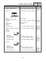
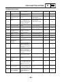
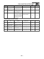
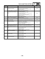
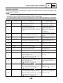
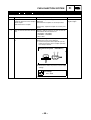
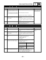
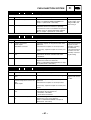
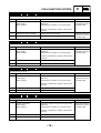
FUEL INJECTION SYSTEM
Fault code No.
Er-1
Symptom
FI
No signals are received from the ECU.
Used diagnostic code No. – –
Order
1
Item/components
Check or maintenance job
Restore method
Coupler connections
ECU coupler
Meter couplers
Check the couplers for any pins that may have
pulled out.
Check that the couplers are securely locked.
Reinstated automatically when it receives
a normal signal.
If there is a malfunction, repair it and connect it
securely.
2
Malfunction in meter assembly
Replace the meter assembly.
3
Malfunction in ECU
Replace the ECU.
Fault code No.
Er-2
Symptom
Reinstated automatically when it receives
a normal signal.
No signals are received from the ECU within the specified duration.
Used diagnostic code No. – –
Order
1
Item/components
Check or maintenance job
Restore method
Coupler connections
ECU coupler
Meter couplers
Check the couplers for any pins that may have
pulled out.
Check that the couplers are securely locked.
Reinstated automatically when it receives
a normal signal.
If there is a malfunction, repair it and connect it
securely.
2
Malfunction in meter assembly
Replace the meter assembly.
3
Malfunction in ECU
Replace the ECU.
Fault code No.
Er-3
Symptom
Data from the ECU cannot be received correctly.
Used diagnostic code No. – –
Order
1
Item/components
Check or maintenance job
Restore method
Coupler connections
ECU coupler
Meter couplers
Check the couplers for any pins that may have
pulled out.
Check that the couplers are securely locked.
Reinstated automatically when it receives
a normal signal.
If there is a malfunction, repair it and connect it
securely.
2
Malfunction in meter assembly
Replace the meter assembly.
3
Malfunction in ECU
Replace the ECU.
Fault code No.
Er-4
Symptom
Non-registered data has been received from the meter.
Used diagnostic code No. – –
Order
1
Item/components
Check or maintenance job
Restore method
Coupler connections
ECU coupler
Meter couplers
Check the couplers for any pins that may have
pulled out.
Check that the couplers are securely locked.
Reinstated automatically when it receives
a normal signal.
If there is a malfunction, repair it and connect it
securely.
2
Malfunction in meter assembly
Replace the meter assembly.
3
Malfunction in ECU
Replace the ECU.
– 70 –
–
ELEC
ELECTRICAL COMPONENTS
+
EAS00729
ELECTRICAL SYSTEM
ELECTRICAL COMPONENTS
1 Spark plug
2 Spark plug cap
3 Ignition coil
4 Intake air pressure sensor
5 Front brake light switch
6 Right handlebar switch
7 Immobilizer unit
8 Main switch
9 Fuel pump
0 Clutch switch
A Left handlebar switch
B Throttle position sensor
C Coolant temperature sensor
D Fuel injector
9
6
3
0
E Lean angle cut-off switch
F Turn signal/hazard relay
G Headlight relay
H Radiator fan motor relay
I Relay unit
J Battery
K Fuse box 1
A
B
8
7
D
4
C
E
5
2
H
G
1
I
Z
F
[
J
K
Y
L
\
M
W
X
N
V
O
T
U
S
– 71 –
R
Q
P
L Fuse box 2
M Starter relay
N Main fuse
O Rectifier/regulator
P ECU
Q Intake air temperature sensor
R Sidestand switch
S Neutral switch
T Crankshaft position sensor
U Stator coil
V Rear brake light switch
3
+
W Speed sensor
X Starter motor
Y Radiator fan motor
Z Horn
[ Air induction system solenoid
\ O2 sensor
9
6
–
ELEC
ELECTRICAL COMPONENTS
0
A
B
8
7
D
4
C
E
5
2
H
G
1
I
Z
F
[
J
K
Y
L
\
M
W
X
N
V
O
T
U
S
– 72 –
R
Q
P
XT660R(W)/XT660X(W) 2007 WIRING DIAGRAM
1 Crankshaft position sensor
2 A.C. magneto
3 Neutral switch
4 Main switch
5 Rectifier/regulator
6 Battery
7 Main fuse
8 Starter relay
9 Starter motor
0 Fuel injection system fuse
A Backup fuse (immobilizer
unit, meter assembly)
B Radiator fan motor fuse
C Right handlebar switch
D Engine stop switch
E Start switch
F Front brake light switch
G Relay unit
H Starting circuit cut-off relay
I Fuel injection system relay
J Sidestand switch
K Fuel pump
L ECU
M Ignition coil
N Spark plug
O Fuel injector
P Air induction system solenoid
Q Intake air temperature sensor
R Coolant temperature sensor
S Speed sensor
T Throttle position sensor
U Intake air pressure sensor
V Lean angle cut-off switch
W Meter assembly
X Neutral indicator light
Y Multifunction meter
Z Coolant temperature warning
light
[ Engine trouble warning light
\ Fuel level warning light
] High beam indicator light
_ Turn signal indicator light
a Immobilizer system indicator
light
b Headlight relay
c Turn signal/hazard relay
d Left handlebar switch
e Horn switch
f Pass switch
g Dimmer switch
h Turn signal switch
i Hazard switch
j Clutch switch
k Horn
l Headlight
m Rear turn signal light (left)
n Front turn signal light (left)
o Front turn signal light (right)
p Rear turn signal light (right)
q Radiator fan motor relay
r Radiator fan motor
s Rear brake light switch
t Auxiliary light
u Tail/brake light
v Ignition fuse
w Signaling system fuse
x Headlight fuse
y Parking lighting fuse
z Immobilizer unit
{ Anti-theft alarm (optional)
| O2 sensor
È Optional
COLOR CODE
B ............Black
Br ...........Brown
Ch ..........Chocolate
Dg ..........Dark green
G ............Green
Gy ..........Gray
L.............Blue
Lg...........Light green
O ............Orange
P ............Pink
R ............Red
Sb ..........Sky blue
W ...........White
Y ............Yellow
B/L .........Black/Blue
B/W ........Black/White
B/Y.........Black/Yellow
Br/L ........Brown/Blue
Br/R .......Brown/Red
Br/W.......Brown/White
G/L .........Green/Blue
G/R ........Green/Red
G/W .......Green/White
G/Y ........Green/Yellow
Gy/G ......Gray/Green
L/B .........Blue/Black
L/G .........Blue/Green
L/R .........Blue/Red
L/W ........Blue/White
L/Y .........Blue/Yellow
O/R ........Orange/Red
P/W ........Pink/White
R/B.........Red/Black
R/G ........Red/Green
R/L .........Red/Blue
R/W........Red/White
R/Y.........Red/Yellow
Y/B.........Yellow/Black
Y/G ........Yellow/Green
Y/L .........Yellow/Blue
XT660R(W)/XT660X(W) 2007
WIRING DIAGRAM
XT660R(W)/XT660X(W) 2007
SCHALTPLAN
XT660R(W)/XT660X(W) 2007
SCHÉMA DE CÂBLAGE
XT660R(W)/XT660X(W) 2007
DIAGRAMA ELÉCTRICO
XT660R(W)/XT660X(W) 2007
SCHEMA ELETTRICO
A
Ch Lg L/R
G Y B
L/R G Ch
B Y Dg
Gy G/W
W W
W
W
Gy G/W
G/W L/Y
MAIN HARNESS SUB-WIRE HARNESS
1
W W
W
W
W
2
W
W
W
5
R
B
Sb
R
R
R
R
R R
P L/W
B/Y R/L
L
B
3
R
B
B
B
R
7
8
6
W W W
R/W
R/B
R
Gy
L/W
R/L
B
R
4
ON
OFF
P
B
Br/R
Br/R
R
R
Br/L
Br/L
L/W R/B
L/W
Br
9
G
O
O
R/B
R/B
O
Lg
I
H
Br L/W
R/W B/Y R/LL/R
L/B
Br/L
Br/R
R
0
R/G B2 B
R/W Lg Y /L
R
B
R/B
D
R/G
R
R L/B
L/W R/W
R/B B
B R/B
L/B
R/W
Sb L/Y L/G
Gy/G
Br
E
Gy/G
Gy
L/G
(BLUE)
B
B
(BLACK)
R
G/W B
J
-
B
B
B
B
Br/R
Br/W
Br/W
X
B/L
Br/W B/L
R
G/R
A
G/R
B/L
(BLACK)
{
Br/L
B2 B1
B
B
B
B
v
Z
[
\
]
^
a
R
w
Br
Br/L
B1 BB
BB3 BB2
BB4 BB1
Br/L
x
R/L
Y
Br/R
y
Ch
G
Br
R/W
Br
G/L
R/L
R/Y
q
Br
L
R/W
b
R/L
G/Y
R/Y
Y/B
L
r
L/W
Y/B
Br/W
d
B
Br
e
R/L
L/W
Br/W
f
-
g
h
B
G Y L/W Br/W R/L
Ch
P Lg Br
G G/L R/W
B/W Lg
G/W Y/L
L/Y
i
j
B
B/Y
P
Y
Lg
Ch
G
Y
Br Y
Y Lg
A A
Y G
L/R
A
L/R
L/R
L/R Y
Y
B L Y
B
B L/R
u
B
k
Ch
A
Ch
G
A
Dg
Ch
Dg
G
B
Y G
t
L/R B
Ch
G
Y L/R B
L/Y B/Y
-
R/Y Br/W L/B Y Dg
Ch
Br G P
B
m
n
o
p
P
l
B
B
B
B
A
B
B
Y/L G/W
Ch R/G Y
-
s
Lg B/W
Y R/G Ch
Br
-
Br
R/W G/L Dg
Br/W
B
L
(BLACK)
(BLACK)
c
L/W
L G/Y
B
R
Br
Y/L
B/W
Y
B
B
B
Br/R R/W
(BLACK)
Lg
R/W
R/G
G/W
R/W
Q
Y/L
W
P
(DARK BLUE)
L
B
(BLACK)
BB
B1
BB3
BB4
BB2
BB1
P RW
Gy/G Gy
(BLACK)
R/L B
(DARK GREEN)
|
W L
(BLACK)
K
Br/R
B
(BLUE)
Y
Br Y
B B
R/L G/W
L/G B
F
Br
R/G
G/L
R/W
BB
Y/L
B
z
R/LR/B
P
L/R
B/Y
L/B
C
Br
A
Y/L G/L R/W
R/L
(GRAY)
R/B L/B R/L
L/W L/R R/W L/G L/Y S b B/Y L g
P
B B B R/G
M
N
L/W
B
B
L Br/R R R/B O
Y/L Y/G Gy/G W Gy B/W
B
L/B G/R Br/W P/W Y B/L L /R G/Y Y/B
R
R/W L/W
G/R B/L
L
W
B/L
L
W
B/L
Y/B
G/Y
Y
L
Y
B/L
P/W
L
P/W
B/L
Y/G
L
Y/G
B/L
T
L Y B/L
(BLACK)
U
B/L P/W L
(BLACK)
B/W
B
V
L Y/G B/L
S
P O/R
B/W
L
W
B/L