1
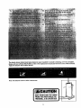
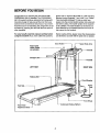
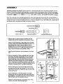
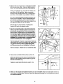
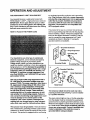
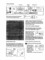
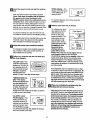
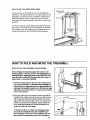
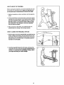
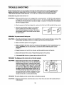
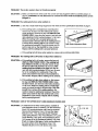
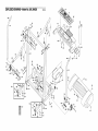
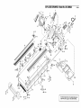
590
LS
CROSSWALK
USER'S MANUAL
Model No. 831.299620
Serial No.
Write the serial number in the space
above for future reference.
_e
rial
Number
Decal
EXIE
E(_
[oRI
RC
u
n
I
;i_,_Bi
I S
PM
iill
_-
ENT
Re|
# nl
HELPLINE!
1-800-736-6879
SEARS, ROEBUCK AND CO.
HOFFMAN ESTATES, IL 60179
www.proform.com
new products, prizes,
fitness tips, and much morel
TABLE
OF CONTENTS
IMPORTANT
PRECAUTIONS
.....................................................
BEFORE YOU BEGIN ..................................................................
2
4
ASSEMBLY
5
...........................................................................
OPERATION
AND ADJUSTMENT
........................................................
HOW TO FOLD AND MOVE THE TREADMILL
TROUBLE-SHOOTING
CONDITIONING
ORDERING
FULL 90-DAY
..............................................................
GUIDELINES
REPLACEMENT
WARRANTY
Note: An EXPLODED
IMPORTANT
...............................................
12
....................................................
PARTS
...............................................
........................................................
DRAWING
is attached
in the center
PRECAUTIONS
2
7
10
14
Back Cover
Back Cover
of thMs manual.
The decals shown below have been placed on your treadmill. If a decal is missing, or if it is not legible,
please call our toll-free HELPLINE to order a free replacement decal (see the front cover of this manual).
Apply the decal in the location shown.
Note: This decal is shown at 38% of actual size.
FROMTHISAREAWHILETHE
KEEPHANDS
TREADMILL
ISANDFEETAWAYl-INOPERATION.•
I
3
BEFORE YOU BEGIN
Congratulations for selecting the new PROFORM ®
CROSSWALK 590 LS treadmill. The CROSSWALK
590 LS treadmill combines advanced technology with
innovative design to help you get the most from your
exercise in the convenience and privacy of your home.
And when you're not exercising, the unique 590 LS can
be folded up, requiring less than half the floor space of
other treadmills.
please call our toll-free HELPLINE at 1-800-736-6879,
Monday through Saturday, 7 a.m. until 7 p.m. Central
Time (excluding holidays). To help us assist you,
please note the product model number and serial number before calling. The model number of the treadmill
is 831.299620. The serial number can be found on a
decal attached to the treadmill (see the front cover of
this manual for the location).
For your benefit, read this manual carefully before
using the treadmill, If you have additional questions,
Before reading further, please review the drawing below
and familiarize yourself with the parts that are labeled.
Water Bottle
Holder (Bottle
not included)
Book Holder -----_
Key/Clip z'---
Storage Latch
[_---
Upper Body Arms
_Console
___
--
Handrail
illOH
LEFT SIDE
Walking Belt
Circuit Breaker
Power
Cord
Foot Rail
Front Wheel
Cushioned Walking Platform
Rear Roller
Adjustment
4
ASSEMBLY
Assembly requires two people. Set the treadmill in a cleared area and remove all packing matedals. Do not
dispose of the packing materials until assembly is completed. Refer to the drawings below to identify small parts
used in assembly. Assembly requires the following tools: The included allen wrench and your own phillips
screwdriver
(]__,
mallet (z_
, wire cutters _,
and needle-nose pliers _.
Note: The underside of the treadmill walking belt is coated with high-performance lubricant. During shipping, a
small amount of lubricant may be transferred to the top of the walking belt or the shipping carton. This is a normal
condition and does not affect treadmill performance. If there is lubricant on top of the walking belt, simply wipe off
the lubricant with a soft cloth and a mild, non-abrasive cleaner.
Long Screw (79)-4
Screw (101)-4
1©
Handrail Bolt (89)-4
Handrail Washer (92)-4
1. With the help of a second person, carefully raise the
Uprights (82) until the treadmill is in the position shown.
Insert one of the Extension Legs (103) into the treedmill
as shown. Make sure that the Thick Base Pad (97) is on
the indicated side. Note: It may be helpful to tip the
Uprights (82) In the direction shown by the arrows as you
insert the Extension Leg. To fully insert the Extension
Leg, it may be necessary to tap it with a mallet.
Insert the other Extension Leg (not shown) in the same
way.
2. Refer to drawing 2a. If there are plastic ties in the Cage
Nuts (36) in the Right Handrail (85), remove the plastic
ties. Pull about 6 _ of the Wire Hamess (17) out of the
Right Upright (82). Route the Wire Hamass through the
bracket on the Right Handrail and out of the indicated
hole. If necessary, use needle-nose pliers to gdp the conhectors on the Wire Harness. Thread the included wire tie
through the indicated hole in the Right Handrail (85).
2a
85
Refer to drawing 2b. Look into the Right Handrail (85)
and make sure that the Wire Hamess (17) is on the indicated side of the wire tie. Tighten the wire tie and cut the
excess off the end.
Refer to drawing 2c. Insert the bracket on the Right
Handrail (85) into the upper end of the right Upright (82).
Hand tighten a Handrail Bolt (89) with a Handrail Washer
(92) into each side of the Upright as shown.
Attach the Left Handrail (23) as described above. Note:
There is not a wire in the left Upright (82).
5
2cy23 17
_
84
92
_82
2b
Tie
I
3.
With the help of a second person, carefully tip the Uprights
(82) down as shown. Note: It may be helpful to place a
foot on one of the Wheels (95) as you tip the treadmill.
3
Attach each Extension Leg (103) with two Screws (101)
and a Base Pad (52) as shown. Make sure that the
Extension Legs are fully inserted into the Uprights (82);
push down on the Uprights as you tighten the Screws.
52
Note: One replacement Base Pad (52) and Spacer (not
shown) may be included. If a Base Pad becomes worn
and needs to be replaced, use the replacement Base
Pad. If a Thick Base Pad (97) needs to be replaced, use
the replacement Base Pad with the Spacer.
"_101
95
With the help of a second person, carefully tip the
Uprights (82) back to the upright position.
4. Place the Console Base (87) on the Handrails (85, 23).
Make a loop with the indicated plastic tie and insert the
two Wires (17) through the loop. Pull out just enough of
the two Wires to connect them to the connectors in the
Console Base, and then plug the Wires into the connectors. Important: Make sure that the Wi=_s are fully inserted. Tighten the loop and cut off the excess plastic tie.
WARNING: Do not disconnect or connect the Wires
while the treadmill power cord is plugged in.
4a
Tie
Refer to drawing 4b. Thread four Long Screws (79) intothe
Handrails (85, 23) and the Console Base (87). After all four
Long Screws have been started, tighten the Screws
until they are snug; do not overtighten the Screws.
Refer to drawing 2c. Tighten the four Handrail Bolts (89).
79
5. Remove the Lock Knob (105) from the Lock Pin (11).
Make sure that the Lock Pin Collar (14) and the Spring
(56) are on the Lock Pin as shown. Insert the Lock Pin
into the Latch Bracket (77).
Tighten the Lock Knob (105) onto the Lock Pin (11 ).
105
77
14
11
6. Make sure that all parts are tightened before you use the treadmill, Keep the included allen wrench in a
secure place. The allen wrench is used to adjust the walking belt (see page 13). To protect the floor, place a
mat under the treadmill.
OPERATION AND ADJUSTMENT
THE PERFORMANT
LUBE TM WALKING BELT
an equipment-grounding conductor and a grounding
plug. Plug the power cord into a surge suppressor,
and plug the surge suppressor into an appropriate
outlet that is properly installed and grounded in
accordance with all local codes and ordinances.
Your treadmill features a walking belt coated with
PERFORMANT LUBE TM, a high-performance lubricant.
IMPORTANT: Never apply silicone spray or other
substances to the walking belt or the walking platform. Such substances will deteriorate the walking
belt and cause excessive wear.
Important: The treadmill is not compatible with
GFCI-equipped outlets.
This product is for use on a nominal 120-volt circuit,
and has a grounding plug that looks like the plug illustrated in drawing 1 below. A temporary adapter that
looks like the adapter illustrated in drawing 2 may be
used to connect the surge suppressor to a 2-pole
receptacle as shown in drawing 2 if a properly
grounded outlet is not available.
HOW TO PLUG IN THE POWER CORD
I
Your treadmill, like any other type of sophisticated
electronic equipment, can be seriously damaged by
sudden voltage changes in your home's power.
Voltage surges, spikes, and noise interference can
result from weather conditions or from other appliances
being tumed on or off. To decrease the possibility of
your treadmill being damaged, always use a surge
suppressor with your treadmill (see drawing 1 at
the right). To purchase a surge suppressor, see
your local SEARS or call 1-800-366-7278 and order
part number 146148.
G
Grounded Outlet
s°uU',:
s .C pressor
(_munding Plug"_
'-_L-Grounded Outlet Box
( "J
Use only a single-outlat surg e suppressor that is
UL 1449 listed as a transient voltage surge suppressor (TVSS). The surge suppressor must have a
UL suppressed voltage rating of 400 volts or-less
and a minimum surge dissipation of 450 Joules.
The surge suppressor must be electrically rated
for 120 volts AC and 15 amps. There must be a
monitoring light on the surge suppressor to indicate whether it is functioning properly. Failure to
use a properly functioning surge suppressor could
result in damage to the control system of the
treadmill. If the control system is damaged, the
walking belt may change speed or stop unexpectedly, which may result in a fall and serious injury.
_1
Adapter
'
Surge_uppressor
The temporary adapter should be used only until a
properly grounded outlet (drawing 1) can be installed
by a qualified electrician.
The green-colored rigid ear, lug, or the like extending
from the adapter must be connected to a permanent
ground such as a properly grounded outlet box cover.
Whenever the adapter is used it must be held in place
by a metal screw. Some 2-pole receptacle outlet box
covers are not grounded. Contact a qualified electrician to determine if the outlet box cover is
grounded before using an adapter.
This product must be grounded, If it should malfunction or break down, grounding provides a path of least
resistance for electric current to reduce the dsk of electric shock. This product is equipped with a cord having
7
CONSOLE DIAGRAM
LED Track
Displays
Speed Control
,nc,ine
I /
\_
_Control
,
_.oP,__o°JJ
....
i_
Note: If there is a thin sheet of clear plastic
on the face of the console, remove it.
K_y_"_"-'_f@_]---
I
Clip
negative (-) ends of the battedes are touching the
springs in the battery compartment. Close the battery
cover, push up on the battery cover tab, and then push
the tab forward as shown in the inset drawing. Be sure
that the tab locks into place.
STEP-BY-STEP CONSOLE OPERATION
Before operating the console, make sure that the
power cord is pmpedy plugged in. (See HOW TO
PLUG IN THE POWER CORD on page 7.)
Stand on the foot rails of the
treadmill. Find the clip attached to the key and slide
the clip onto the waistband
of your clothes. Next, insert
the key into the console.
Test the clip by carefully taking a few steps backward until the key is pulled from the console. If the
key Is not pulled from the console, adjust the position of the clip as needed.
Follow the steps below to operate the console.
BATTERY INSTALLATION
The console requires three "AA" batteries (not included). Alkaline battedes are recommended. Open
the battery cover as shown below. Insert three batteries into the battery compartment, making sure that the
Insert the key fully Into the power switch.
Inserting the key will
not turn on the dis-
=---
plays. The displays will
t %
tum on when the
ON/RESET button is
pressed or when the
walking belt is started.
Note: If you just
installed batteries, the displays will already be on,
Battery
Cover
Tab
8
B
SPEED display--This
display shows the speed
of the walking belt, in
miles per hour.
Reset
belt. the speed control and start the walking
Slide the speed control to the RESET position.
(Note: Each time the walking belt is stopped,
the speed control must be moved to the
RESET position before the walking belt can be
restarted.) Next, slowly slide the speed control to
the dght until the walking belt begins to move at
slow speed. Step onto the walking belt and begin
walking. As you exercise, change the speed of the
walking belt as desired with the speed control.
To reset the displays at any time, press the
ON/RESET button.
B
Note: Dudng the first few minutes that you use the
treadmill, inspect the alignment of the walking
belt, and align it if necessary (see page 13).
" IB5
Adjust the Incline of the treadmill as desired.
To change the incline of the treadmill, press the
top or bottom of the incline control until the desired incline level is reached.
B
Follow your progress with the LED track and
the three displays.
The LED Track--The
LED track represents a
Io
@ @ @ @ @
distance of 1/4 mile. As
you exercise, the indicators around the track
will light in sequence
until you have cornpleted 114 mile. A new lap willthen begin.
°
Measure your heart rate, if desired.
To measure your heart
rate, stand on the foot
Pulse Sensor
rails and place your
thumb on the pulse
sensor as shown. The
pulse sensor is pressure ectivated--fuUy
press it down. Do not
PULSE
press too hard, or the
circulation In your
thumb will be reCALS.
FAT CALS.
stricted, and your
pulse will not be detected. Next, raise your thumb slightly until the
heart-shaped indicator in the CALS/FAT
CALS/PULSE display flashes steadily. Hold your
thumb at this level. After a few seconds, three
dashes will appear in the display and then your
heart rate will be shown. Hold your thumb on the
pulse sensor for another 15 seconds for the most
accurate reading.
To stop the walking belt, step onto the foot rails
and slide the speed control to the RESET position.
B
SPEED
Ooo
If the displayed heart rate appeam to be too high
ortoo low, or if your heart rate is not displayed, lift
your thumb off the pulse sensor and allow the display to reset. Then, press down on the pulse sensor as described above. Make sure that your thumb
is positionedas shown, and that you are applying
the proper amount of pressure. Remember to stand
stillwhile meesudng your heart rate.
TIME/DISTANCE disArrow
play--This display
shows the elapsed time
and the distance that
you have walked or run,
TIME
DISTANCE
in miles. Every few seconds, the display will
change from one number to the other, as shown
by the arrows in the display.
r_
When you are finished exercising, stop the
walking belt and remove the key.
Step onto the foot rails, slide the speed control to
the RESET position, and adjust the incline of the
treadmill to the lowest level. The incline must be
at the lowest level when the treadmill is ralead
to the storage position. Remove the key from
the console. The displays will turn off about five
minutes after the key is removed. Note: To conserve the batteries, the displays will automatically turn off any time that the walking belt is
stopped and the ON/RESET button is not
pressed for five mlnutes,
CALS/PAT CALS/
PULSE
PULSE display--This
display shows the approximate numbers of
calories and fat calories
CALS. FATCALS.
you have burned. (See
FAT BURNING on page
14.) Every few seconds, the display will change
from one number to the other,
9
I
HOW TO USE THE UPPER BODY ARMS
As you exercise on the treadmill, you can hold either the
handrails or the upper body arms. The upper body arms are
designed to exercise your arms, shoulders, and back for a
total body workout. Hold one upper body arm with each
hand, and move them forward and back as you walk on the
treadmill.
To vary the intensity of your upper body exercise, the resistance of the upper body arms can be adjusted. To increase
the resistance, turn the resistance knobs clockwise; to decrease the resistance, turn the knobs counterclockwise.
HOW TO FOLD AND MOVE THE TREADMILL
HOW TO FOLD THE TREADMILL
FOR STORAGE
Before folding the treadmill, adjust the Incline to the
lowest position. If this is not done, the treadmill may be
damaged. Next, unplug the power cord. CAUTION: You
must be able to safely lift 45 pounds (20 kg) in order to
raise, lower, or move the treadmill.
1. Hold the treadmill with your hands in the locations shown
at the dght. (CAUTION: To decrease the possibility of
injury, bend your legs and keep your back straight. As
you raise the treadmill, make sure to lift with your legs
rather than your back.) Raise the treadmill about halfway
to the vertical position.
2. Move your dght hand to the position shown and hold the
treadmill firmly. Hold the lock knob with your left hand and
pull it to the left. Raise the treadmill until the lock knob is
aligned with the slot in the catch. (Note: You may need to
push the handrail to the left slightly). Slowly release the
knob; make sure that the pin on the lock knob is inserted into the slot In the catch.
To protect the floor or carpet from damage, place a
mat under the treadmill. Keep the treadmill out of
direct sunlight. Do not leave the treadmill in the storage position in temperatures above 85 ° Fahrenheit.
10
2
Slot
HOW TO MOVE THE TREADMILL
Before moving the treadmill, convert the treadmill to the storage position as described above. Make sure that the pin
on the lock knob is inserted into the slot in the catch.
1. Hold the handrails as shown and place one foot against a
wheel.
2. Tilt the treadmill back until it rolls freely on the front wheels.
Carefully move the treadmill to the desired location. Never
move the treadmill without tipping it back. To reduce
the risk of injury, use extreme caution while moving
the treadmill. Do not attempt to move the treadmill
over an uneven surface.
ase
3. Place one foot on the wheel, and carefully lower the
treadmill until it is resting in the storage position.
HOW TO LOWER THE TREADMILL
els
FOR USE
1. Hold the upper end of the treadmill with your right hand as
shown. Using your left hand, pull the lock knob to the left
and hold it. Pivot the treadmill until the frame and foot rail
am past the pin on the lock knob. If necessary, push the
handrail to the left slightly.
2. Hold the treadmill firmly with both hands, and lower the
treadmill to the floor. Do not drop the treadmill frame to
the floor. To decrease the possibility of injury, bend
your legs and keep your back straight.
11
Slot
TROUBLE-SHOOTING
Most treadmill problems can be solved by following the simple steps below. Find the symptom that
applies, and follow the steps listed. If further assistance is needed, call our toU-free HELPLiNE at
1-800-736-6879, Monday through Saturday, 7 a.m, until 7 p.m. Central Time (excluding holidays).
PROBLEM:
The power does not turn on
SOLUTION: a. Make sure that the power cord is plugged into a surge suppressor, and that the surge suppressor
is plugged into a properly grounded outlet (see page 7). Use only a single-outlet surge suppressor
that meets all of the specifications described on page 7. Important: The treadmill is not compatible
with GFCl-equipped outlets.
b. After the power cord has been plugged in, make sure that the key is fully inserted into the console.
c. Check the circuit breaker located on the treadmill
near the power cord. If the switch protrudes as
shown, the circuit breaker has tripped. To reset the
circuit breaker, wait for five minutes and then press
the switch back in.
PROBLEM:
Ic
I
Tripped
Reset
The power tums off during use
SOLUTION: a. Check the circuit breaker located on the treadmill frame near the power cord (see c. above). If the
circuit breaker has tripped, wait for five minutes and then press the switch back in,
b. Make sure that the power cord is plugged in.
c. Make sure that the two wires under the console are fully plugged in (refer to assembly step 4 on
page 6). WARNING: Do not disconnect or connect the wires while the power cord is
plugged in.
d. Unplug the power cord, wait for five minutes, and then plug the power cord back in.
e. Remove the key from the console. Reinsert the key fully into the console.
f. if the treadmill still will not run, please call our toll-free HELPLINE.
PROBLEM:
The displays on the console do not function properly
SOLUTION:
a. Remove the key from the console and unplug the
power cord. Remove the screws from the hood and
carefully remove the hood. Locate the Reed Switch
(21) and the Magnet (43) on the left side of the Pulley
(42). Turn the Pulley until the Magnet is aligned with
the Reed Switch. Make sure that the gap between
the Magnet and the Reed Switch is about 118". If
necessary, loosen the Reed Switch Screw (76) and
move the Reed Switch slightly. Retighten the Screw.
Re-attach the hood, and run the treadmill for a few
minutes to check for a correct speed reading.
PROBLEM:
The pulse display on the console does not function properly
SOLUTION:
a. Wash your hands before using the pulse sensor. Clean the pulse sensor with a damp cloth and
mild detergent.
12
PROBLEM:
The incline system does not function properly
SOLUTION:
a. Make sure that the two wires under the console are fully plugged in (refer to assembly step 4 on
page 6). WARNING: Do not disconnect or connect the wires while the treadmill power cord is
plugged in.
PROBLEM: The walking belt slows when walked on
SOLUTION:
a. Use only a single-outlet surge suppressor that meets all of the specifications described on page 7.
b. If the walking belt is overtightened, treadmill performance may decrease and the walking belt may become damaged. Remove the key and UNPLUG THE
POWER CORD. Using the allen wrench, turn both rear
roller adjustment bolts counterclockwise, 1/4 of a turn.
When the walking belt is propedy tightened, you
should be able to lift each side of the walking belt 3 to
4 inches off the walking platform. Be careful to keep
the walking belt centered. Plug in the power cord, insert the key and run the treadmill for a few minutes.
Repeat until the walking belt is propedy tightened.
b
Rear Roller Adjustment Bolts
c. If the walking belt still slows when walked on, please call our toll-free HELPLINE.
PROBLEM:
The walking belt is off-center or slips when walked on
SOLUTION: a. If the walking belt is off-center, remove the key and
UNPLUG THE POWER CORD. If the walking belt
has shifted to the left, use the allen wrench to tum
the left rear roller bolt clockwise 1/2 of a turn; if the
walking belt has shifted to the right, turn the left
rear miler bolt counterclockwise 1/2 of a turn. Be careful not to overtighten the walking belt. Plug in the
power cord, insert the key and run the treadmill for a
few minutes. Repeat until the walking belt is centered.
b. If the walking belt slips when walked on, first remove
the key and UNPLUG THE POWER CORD. Using
the allen wrench, turn both rear miler bolts clockwise,
1/4 of a turn. When the walking belt is correctly tightened, you should be able to lift each side of the walking belt 3 to 4 inches off the walking platform. Be
careful to keep the walking belt centered. Plug in the
power cord, insert the key and carefully walk on the treadmill for a few minutes. Repeat until the walking
belt is properly tightened.
PROBLEM:
b
ONE OF THE UPPER BODY ARMS SQUEAKS DURING USE
SOLUTION: a. A small amount of white marine grease, available at
most hardware stores, is needed. Turn the Resistance
Knob (119) counterclockwise until it can be removed.
Remove the Resistance Cone (114) and the Upper
Body Arm (t t0, 115), along with the 3/8" Washers
(108), Spdng Washer (116), Thrust Washers (117), and
Thrust Bearing (118). (Note: If the Resistance Sleeve
[113] comes out of the Resistance Bracket [112], press
it back in.) Apply a thin layer of white marine grease to
the outer surface of the Resistance Cone (114).
Reattach all parts in the order shown at the right.
13
112
113
115
CONDITIONING
GUIDELINES
is to burn fat, adjust the speed and incline of the treadmill until your heart rate is near the lowest number in
your training zone.
For maximum fat burning, adjust the speed and incline
of the treadmill until your heart rate is near the middle
number in your training zone.
Aerobic Exercise
The following guidelines will help you to plan your exercise program. For more detailed exercise information, obtain a reputable book or consult your physician.
EXERCISE INTENSITY
If your goal is to strengthen your cardiovascular system, your exercise must be "aerobic." Aerobic exercise
is activity that requires large amounts of oxygen for
prolonged periods of time. This increases the demand
on the heart to pump blood to the muscles, and on the
lungs to oxygenate the blood. For aerobic exercise,
adjust the speed and incline of the treadmill until your
heart rate is near the highest number in your training
zone.
WORKOUT
Whether your goal is to bum fat or to strengthen your
cardiovascular system, the key to achieving the
destred results is to exercise with the proper intensity.
The proper intensity level can be found by using your
heart rate as a guide. The chart below shows recommended heart rates for fat buming and aerobic exercise.
E TRAINING ZONES
20
30
40
50
80
70
80
To find the proper heart rate for you, first find your age
near the bottom of the chart (ages are rounded off to
the nearest ten years). Next, find the three numbers
above your age. The three numbers define your "training zone." The lower two numbers are recommended
heart rates for fat burning; the higher number is the
recommended heart rate for aerobic exercise.
GUIDELINES
Each workout should include the following three pads:
A Warm-up_Stad each workout with 5 to 10 minutes
of stretching and light exercise. A proper warm-up increases your body temperature, heart rate and circulation in preparation for exercise.
Training Zone Exercise--After warming up, increase
the intensity of your exercise until your pulse is in your
training zone for 20 to 60 minutes. (Dudng the first few
weeks of your exercise program, do not keep your
pulse in your training zone for longer than 20 minutes.)
Breathe reguledy and deeply as you exemise--never
hold your breath.
A Cool-down---Finish each workout with 5 to 10 minutes of stretching to cool down. This will increase the
flexibility of your muscles and will help prevent post-exercise problems,
EXERCISE FREQUENCY
Fat Burning
To maintain or improve your condition, complete three
workouts each week, with at least one day of rest between workouts. After a few months, you may complete up to five workouts each week if desired.
To burn fat effectively, you must exercise at a relatively
low intensity level for a sustained period of time.
During the first few minutes of exercise, your body
uses easily accessible carbohydrate calories for energy. Only after the first few minutes does your body
begin to use stored fat calories for energy. If your goal
The key to success is to make exercise a regular and
enjoyable part of your everyday life.
14
PART LISTmModel
No. 831.299620
RO O2A
To locate the parts listed below, refer to the EXPLODED DRAWING attached in the center of this manual.
Key
No.
Qty.
1
2
3
4*
1
1
4
1
5
6
7
8
9
10
11
12
13
14
15
16
17
18
19
20
21
22
23
24
25
26
27
28
29
30*
31
32
33
34
35
36
37
38
39
40
41
42
43
44
45
46
2
2
8
4
1
2
1
2
20
1
1
2
2
1
1
4
1
4
2
1
2
1
1
4
4
4
Description
Motor Belt
Pulley/Flywheel/Fan
Motor Nut
Motor/Pulley/
Flywheel/Fan
Incline Motor Bolt
Incline Motor Spacer
Incline Motor
Stop Bracket
Speed Control
Incline Control
Lock Pin
Frame
Pin Clip
Lock Pin Collar
Incline Motor Nut
Belt Guide Screw
Wire Harness
Rubber Hoed Bracket
Front Hood Bracket
Waming Decal
Reed Switch
Reed Switch Clip
Left Handrail
Controller
Electronics Bracket
Circuit Breaker
Power Cord
Power Cord Grommet
Hood Screw
Latch Assembly
Incline Frame
Frame Pivot Bolt
Frame Pivot Spacer
Tension Bushing
Front Roller Adj. Bolt
Cage Nut
Motor Tension Nut
Motor Bolt
Cap Screw
Foot Rail Cap (Left)
Foot Rail
Front Roller/pulley
Magnet
Platform Screw
Isolator
Isolator Screw
Key
No.
Qty.
47
48
49
50
51
52
53
54
55
56
57
58
59
60
61
62
63
64
65
66
67
68
69
70
71
72
73
74
75
76
13
1
2
1
1
2
3
4
1
1
1
2
2
4
1
1
1
1
2
1
1
4
2
1
1
5
2
1
2
6
77
78*
1
2
79
80
81
82
83
84
85
86
87
88*
89
90
91
4
1
8
1
2
1
1
2
1
1
4
t
1
Description
Belly Pan Fastener
Shield
Belt Guide
Battery Cover
Front Belly Pan
Base Pad
Cable Tie Clamp
Cable Tie
Walking Belt
Spring
Rear Roller
Rear Isolator
Rear Foot
Rear Foot Screw
Ground Wire
Hood Bracket Plate
Belly Pan
Rear Endcep
Rear Roller Adj. Bolt
Motor
Latch Decal
Rear Platform Screw
Latch Catch Screw
Latch Catch
Walking Platform
8 _ Cable Tie
Interface Bracket
Motor Tension Bolt
Foot Rail Insert
Reed Switch Screw/
Belly Pan Screw
Storage Latch Bracket
Extension Leg
Assembly
Long Screw
Wire Cover
Motor Star Washer
Upright
Incline Leg Pivot Bolt
Motor Tension Washer
Right Handrail
Wheel Bolt
Console Base
Console Assembly
Handrail Bolt
Key/Clip
Incline Motor Belly Pan
15
Key
No.
Qty.
92
10
93
94
95
96
97
98
99
100
101
102
103
104
105
106
107
1
1
2
1
4
1
1
1
18
2
2
2
1
1
4
108
109
110
4
2
1
111
112
113
114
115
2
2
2
2
1
116
1t 7
2
4
Roller Adj. Washer/
Handrail Washer
Book Holder
Motor Hood
Front Wheel
Incline Motor Shield
Thick Base Pad
Trim Guard
Upright Grommet
Allen Wrench
Screw
Handrail Endcap
Extension Leg
Extension Leg Cap
Lock Knob
Choke
Resistance Bracket
Bolt
3/8" Washer
Foam Grip
Left Upper Body Arm
w/Foam Gdp
Resistance Bolt
Resistance Bracket
Resistance Sleeve
Resistance Cone
Right Upper Body Arm
w/Foam Gdp
Spdng Washer
Thrust Washer
118
119
120
121
122
#
#
#
2
2
4
1
7
1
1
1
Thrust Bearing
Resistance Knob
Star Washer
Foot Rail Cap (Right)
Console Base Screw
8" White Wire, Pigtail
8" Green Wire, 2 Ring
User's Manual
Description
* Includes all parts shown in the
box
# These parts are not illustrated
EXPLODED DRAWING--Model
No. 831.299620
RO102A
90
,122
92
89
85
102
56
17
13
76
11
,122
14
89
92
l
23
102
36
79
104
s _
111
107
108
117
J
112 113
115
I
116
i
114
29
118
108
29
103
17
119
95
15
94
114
113
98
15
IO0
29
86
EXPLODED DRAWING---Model No. 831.299620
ROlO2A
8
37
27
26
84
29
25
41
75
45
45
39
70
68
55
I
57
To identify the parts shown on this exploded drawing, refer
to the PART LIST on page 15 of the USER'S MANUAL.
SEARS
The model number and serial number of your PROFORM CROSSWALK ®590 LS treadmill are listed on a decal attached to the frame.
See the front cover of this manual to find the location of the decal.
Model No. 831.299620
QUESTIONS?
All replacement parts are available for immediate purchase or
special order when you visit your nearest SEARS Service Center.
To request service or to order parts by telephone, call the toll-free
numbers listed at the left.
If you find that:
• you need help assembling or
operating the PROFORI_P
CROSSWALK 590 LS treadmill
• a part is missing
• or you need to schedule repair
service
When requesting help or service, or ordering pads, please be
prepared to provide the following information:
• The NAME OF THE PRODUCT (PROFORM e CROSSWALK 590
LS treadmill)
• The MODEL NUMBER OF THE PRODUCT (831.299620)
call our toll-f=_e HELPLINE
1-800-736-6879
Monday-Saturday, 7 am-7 pm
Central Time (excluding holidays)
• The KEY NUMBER AND DESCRIPTION OF THE PART (see the
EXPLODED DRAWING and PART LIST in the center of this
manual).
REPLACEMENT
PARTS
If parts become worn and need
to be replaced, call the following
toll-free number
1-800-FON-PART
(1-800-366-7278)
FULL 90 DAY WARRANTY
For 90 days from the date of purchase, if failure occurs due to defect in matedal or workmanship in this
SEARS TREADMILL EXERCISER, contact the nearest SEARS Service Center throughout the United
States and SEARS will repair or replace the TREADMILL EXERCISER, free of charge.
This warranty does not apply when the TREADMILL EXERCISER is used commercially or for rental purposes.
This warranty gives you specific legal rights,and you may also have other rights which vary from state
to state.
SEARS, ROEBUCK AND CO., DEPT. 817WA, HOFFMAN ESTATES, IL 60179
Part No. 181429 RO102A
Printed in USA © 2002 Sears, Roebuck and Co.