1
Quick Start Guide
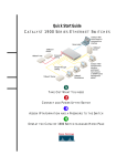
CISCO 2610 ROUTER
CABLING AND SETUP
Windows NT
4.0 server
Windows 95
Telephone
Novell network
PBX
Fax machine
Cisco 2610
Public Service Telephone
Network (PSTN)
Home office PC
Laptop with internal
modem for mobile commuter
1
Take Out What You Need
2
Connect Cables
3
Run Cisco Fast Step
4
Finish the Cabling
5
Network Information - Optional
1 Take Out What You Need
This guide explains how to cable and set up your
Cisco 2610 router with the following
configuration:
•
8- or 16-port internal analog modem in the
network module slot.
•
2 empty WAN interface card slots with a
blank panel in each slot.
Note: If your router has a different hardware
configuration, refer to the Cisco 2600 Series
Hardware Installation Guide for information on
how to install and set up your router.
Begin by taking out the following items from the
box.
Quick Start Guide and
Fast Step CD-ROM
2
M
O
-R
D
C
1 Quick Start Guide (this guide) with
1 Cisco Fast Step CD-ROM (attached)
Router
1 Cisco 2610
POWER
RPS
ACTIVITY
Cisco 2600
SERIES
1 Take Out What You Need (continued)
Cables and Power Cord
1 yellow Ethernet 10BaseT cable
(to connect to a 10BaseT hub)
1 flat, light-blue console cable with
1 RJ-45 adapter, labeled TERMINAL
(RJ-45-to-DB-9 or RJ-45-to-DB-25)
8 or 16 pink modem cables (RJ-11)
3
1 black power cord
2 Connect Cables
SERIAL 1
100-240V– 1A
50/60 Hz 47 W
SERIAL 1
SERIAL 0
CONN
SEE MANUAL BEFORE INSTALLATION
WIC
CONN 2A/S
SERIAL 0
CONN
CONN
WIC
2T
SEE MANUAL BEFORE INSTALLATION
MODEMS
16AM
IN USE
15
14
13
12
11
10
9
8
5
4
3
2
1
0
IN USE
LINK ETHERNET 0 ACT CONSOLE
7
6
Installing a Network Module
Use this procedure, if required, to install an 8- or
16-port analog modem network module in a
Cisco 2610 router.
4
AUX
EN
Look for a network module in the slot labeled 1 on
the left-rear of the router. If there is an analog
modem network module already installed, continue
to cable the router as described in this guide.
If you need to install an analog modem network
module, follow this procedure:
1
Use a Phillips screwdriver to remove the screws
that hold the metal plate over the network
module slot cover and remove the metal
covering plate.
2
Hold the network module by the handle and line
the module up with the guides on either side of
the slot.
3
Push the module into place until the edge
connector is securely seated in the connector on
the motherboard. Ensure that each of the
module’s captive screws line up with their hole in
the chassis.
4
Secure the captive mounting screws into the
holes of the chassis using a Phillips screwdriver.
5
Connect the appropriate network module
cable(s) to your network.
For information on connecting network modules,
refer to the Cisco Network Modules Hardware
Installation Guide included in your router package.
2 Connect Cables (continued)
MODEMS
16AM
15
14
13
12
11
10
9
8
7
6
5
4
3
2
1
0
IN USE
SERIAL 1
100-240V– 1A
50/60 Hz 47 W
SERIAL 1
SERIAL 0
IN USE
CONN
EN
WIC
CONN 2A/S
SERIAL 0
CONN
SEE MANUAL BEFORE INSTALLATION
CONN
WIC
2T
SEE MANUAL BEFORE INSTALLATION
LINK ETHERNET 0 ACT CONSOLE
AUX
Ethernet 10BaseT
port (RJ-45)
10BaseT cable
5
Ethernet hub
(sold separately)
Connect the Ethernet Cable
Position the router so you can reach the rear panel.
The cables and the router’s ports are color-coded to
help you make the right connections.
1
Connect one end of the yellow Ethernet cable
into the yellow Ethernet 10BaseT (RJ-45) port
labeled ETHERNET 0/0 on the rear panel of
your router.
2
Connect the other end of the yellow Ethernet
cable into any available port on your 10BaseT
hub or switch (not included).
3
Make sure a PC (running Windows NT 4.0 or
Windows 95) is connected to the Ethernet LAN.
You will use this computer in the procedure on
page 9 to run Cisco Fast Step software to
configure the router.
2 Connect Cables (continued)
MODEMS
16AM
15
14
13
12
11
10
9
8
IN USE
7
6
5
4
3
2
1
0
EN
SERIAL 1
100-240V– 1A
50/60 Hz 47 W
SERIAL 1
IN USE
CONN
SERIAL 0
WIC
CONN 2A/S
SERIAL 0
CONN
SEE MANUAL BEFORE INSTALLATION
CONN
WIC
2T
SEE MANUAL BEFORE INSTALLATION
LINK ETHERNET 0
CONSOLE
AUX
Console port
(RJ-45)
RJ-45-to-DB-9 or
RJ-45-to-DB-25 adapter
6
Connect the Console Cable
1
Connect the light-blue console cable to the
light-blue port labeled CONSOLE on the rear
panel of the router.
2
Connect the other end of the light-blue console
cable to an RJ-45 adapter.
Use either the RJ-45-to-DB-9 adapter or the
RJ-45-to-DB-25 adapter, depending on your
local PC.
3
Attach the adapter to a serial port on the PC
running Windows NT 4.0 or Windows 95.
2 Connect Cables (continued)
MODEMS
16AM
15
14
13
12
11
10
9
8
IN USE
7
6
5
4
3
2
1
0
EN
SERIAL 1
100-240V– 1A
50/60 Hz 47 W
SERIAL 1
IN USE
SERIAL 0
CONN
WIC
CONN 2A/S
SEE MANUAL BEFORE INSTALLATION
SERIAL 0
CONN
CONN
WIC
2T
SEE MANUAL BEFORE INSTALLATION
LINK ETHERNET 0
CONSOLE
AUX
Analog modem
port (RJ-11)
RJ-11 modem cable
RJ-11 jack
Connect the Modem Cables
The Cisco 2610 router comes with an 8- or 16-port
internal analog modem module. Use these ports to
connect up to 16 modems.
12
9
3
6
Timesaver Start by connecting only one
modem. After you have configured the
router settings for this modem and
completed the procedure on page 9
successfully, connect and set up the
remaining modems.
1
Connect one end of the pink modem cable to one
of the numbered modem ports (also pink) on the
router’s rear panel.
2
Connect the other end of the pink modem cable
to an RJ-11 telephone wall jack or an RJ-11
outlet in your wiring closet.
If you followed the suggestion, in the Timesaver
section on this page, and only connected one cable,
you will have to connect the remaining modem
cables after you configure and test the router. See
page 10, for information on how to finish the
cabling.
7
2 Connect Cables (continued)
MODEMS
16AM
15
14
13
12
11
10
9
8
IN USE
7
6
5
4
3
2
1
0
EN
SERIAL 1
100-240V– 1A
50/60 Hz 47 W
SERIAL 1
IN USE
CONN
SERIAL 0
SEE MANUAL BEFORE INSTALLATION
WIC
CONN 2A/S
SERIAL 0
CONN
CONN
WIC
2T
SEE MANUAL BEFORE INSTALLATION
LINK ETHERNET 0 ACT CONSOLE
AUX
Power switch
Power outlet
Connect Power and
Turn On the Router
8
1
Connect one end of the black power cord to the
power connector on the router’s rear panel.
2
Connect the other end of the power cord to an
electrical outlet.
3
Turn ON the power switch on the rear panel.
The green Power LED on the router’s front panel
blinks, as the router initializes, then stays on
when fully initialized. (It might take a moment
before this light goes on.)
4
Perform a quick visual inspection to ensure the
following:
— The router is plugged in, the power is turned
on, and the Power LED on the front panel
displays a solid green light. (If not, you
cannot install the Cisco Fast Step software.)
— The link LED (labeled LNK) next to the
Ethernet port, displays a solid green light. (If
this is not a solid light, check your cabling.)
— Each modem port you are currently setting
up has a pink modem cable connected to it.
— Each pink modem cable connected to a
modem port is also connected to an RJ-11
telephone wall jack or outlet.
You are now finished cabling the router and one or
more modems. The next section explains how to run
Cisco Fast Step software so you can use the router in
your network.
3 Run Cisco Fast Step
12
9
3
6
Timesaver Cisco Fast Step software
prompts you for network information
according to the routing protocols you
select. Before you run the software, make
sure you have this information available or
know where to get it (usually from the
network administrator).
Once installed, the Cisco Fast Step Setup program
starts automatically. Follow the onscreen
instructions to guide you through configuring and
testing the router.
For your convenience, a form prompting
you for setup information is on page 11.
Perform this test to verify the modem connection and
the router configuration are good. This section
assumes the remote PC you are using for the test runs
Windows NT 4.0 or Windows 95.
Install and Run Cisco Fast Step
1
2
Set Up the Router
Using Fast Step
Verify Connectivity
1
Double-click the My Computer icon on the
desktop of the remote PC.
Insert the Cisco Fast Step CD-ROM (attached to
inside back cover of this guide) into the
CD-ROM drive of the local PC to which you
connected the LAN on page 5.
2
Double-click the Dial-Up Networking folder. (If
you do not find this folder, refer to the Microsoft
documentation to install the software.)
The Fast Step install program starts Setup.exe
automatically. If it does not, follow these steps:
3
Double-click the Make New Connection icon.
4
Follow the onscreen instructions to create and
name a new connection icon to test the modem
connection and the router configuration. When
prompted for the area code and telephone
number, enter the appropriate number of the
modem you are testing.
5
Double-click the new connection icon you
created in Step 4 and enter the username and
password (as defined when setting up Fast Step).
Verify that the telephone number is the correct
number for the modem you are testing.
6
Go to page 10 to connect the remaining modem
cables, if necessary.
(a) Double-click the My Computer icon.
(b) Double-click the CD icon.
(c) Double-click the Setup.exe icon.
The install program prompts you for the
information it needs to install Cisco Fast Step,
then copies the software onto your hard drive.
9
4 Finish the Cabling
This section applies only if your are connecting more
than one modem.
If you connected one modem in the procedure on
page 7, you are now ready to cable the rest of your
modems. How you do this depends on the way you
organize your workspace and your own personal
preferences.
The following suggested procedure helps you
simplify the job by keeping the connections neat and
orderly and by providing a reliable process.
1
Make sure you can reach the router’s rear panel.
2
Pick up a pink modem cable and connect one
end into one modem port (also pink) of the
access server.
3
Repeat Step 2 with the remaining pink modem
cables.
4
Connect the other end of each of the pink
modem cables from Step 3 into an RJ-11 wall
jack or into an RJ-11 outlet in your wiring
closet.
5
Tie-wrap your cable bundles.
6
To help with maintenance and troubleshooting,
write down the access server port number and
telephone wall jack for each modem. Keep this
record in a safe place.
10
5 Network Information - Optional
This appendix is provided to help you gather and organize the information you need to run the Cisco Fast Step
software on page 9.
Login/Security Information
Router name:
Router password (for read-only access):
Super secret password (for read/write access):
IP Routing
IP address list:
LAN-Side IP Address
IP address:
11
Subnet mask:
Dial-In-Side IP Address
Specify the starting range (up to 16 in range) or IP
address list.
Range start:
Note: You can also enter a list of dial-in addresses
instead of a range, or you can specify DHCP.
Internet router IP address (optional):
5 Network Information - Optional (continued)
IPX Routing
IPX network number of LAN side of router:
IPX Frame type (802.3, 802.2, Ethernet II, or SNAP):
ARAP Routing
ARAP network number:
Zone name:
Cable range start:
Cable range end:
Type of Security
12
User list user IDs:
User list password:
Cisco security server IP address:
Cisco security server key:
13
14
15
16
17
Corporate Headquarters
Cisco Systems, Inc.
170 West Tasman Drive
San Jose, CA 95134-1706
USA
http://www.cisco.com
Tel: 408 526-4000
800 553-NETS (6387)
Fax: 408 526-4100
European Headquarters
Cisco Systems Europe s.a.r.l.
Parc Evolic, Batiment L1/L2
16 Avenue du Quebec
Villebon, BP 706
91961 Courtaboeuf Cedex
France
http://www-europe.cisco.com
Tel: 33 1 6918 61 00
Fax: 33 1 6928 83 26
Americas
Headquarters
Cisco Systems, Inc.
170 West Tasman Drive
San Jose, CA 95134-1706
USA
http://www.cisco.com
Tel: 408 526-7660
Fax: 408 527-0883
Asia Headquarters
Nihon Cisco Systems K.K.
Fuji Building, 9th floor
3-2-3 Marunouchi
Chiyoda-ku, Tokyo 100
Japan
http://www.cisco.com
Tel: 81 3 5219 6250
Fax: 81 3 5219 6001
Cisco Systems has more than 200 offices in the following countries. Addresses, phone numbers, and fax numbers are listed on the
C i s c o C o n n e c t i o n O n l i n e W e b s i t e a t h t t p : / / w w w. c i s c o . c o m .
Argentina • Australia • Austria • Belgium • Brazil • Canada • Chile • China (PRC) • Colombia • Costa Rica • Czech Republic •
England • France • Germany • Greece • Hungary • India • Indonesia • Ireland • Israel • Italy • Japan • Korea • Luxembourg •
Mexico • The Netherlands • New Zealand • Norway • Peru • Philippines • Poland • Portugal • Russia • Saudi Arabia • Scotland •
South Africa • Spain • Sweden • Switzerland • Taiwan, ROC • Thailand • Turkey • United Arab Emirates • United States •
Denmark
Malaysia
Singapore
Venezuela
Copyright © 1998 Cisco Systems, Inc. All rights reserved. Printed in USA. AccessPath, AtmDirector, the CCIE logo, CD-PAC, Centri, the Cisco Capital logo, CiscoLink, the Cisco NetWorks logo, the Cisco Powered
Network logo, the Cisco Press logo, ClickStart, ControlStream, DAGAZ, Fast Step, FireRunner, IGX, JumpStart, Kernel Proxy, LoopRunner, MGX, Natural Network Viewer, NetRanger, NetSonar, Packet, PIX,
Point and Click Internetworking, Policy Builder, RouteStream, Secure Script, SMARTnet, SpeedRunner, Stratm, StreamView, The Cell, TrafficDirector, TransPath, VirtualStream, VlanDirector, Workgroup Director,
and Workgroup Stack are trademarks; Changing the Way We Work, Live, Play, and Learn and Empowering the Internet Generation are service marks; and BPX, Catalyst, Cisco, Cisco IOS, the Cisco IOS logo,
Cisco Systems, the Cisco Systems logo, Enterprise/Solver, EtherChannel, FastHub, FastPacket, ForeSight, FragmentFree, IPX, LightStream, MICA, Phase/IP, StrataSphere, StrataView Plus, and SwitchProbe are
registered trademarks of Cisco Systems, Inc. in the U.S. and certain other countries. All other trademarks mentioned in this document are the property of their respective owners. 9805R
Printed in the USA on recycled paper containing 10% postconsumer waste.
DOC-785473=
78-5473-01