1
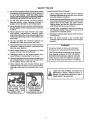
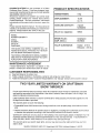
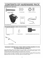
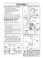
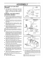
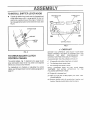
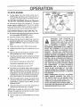
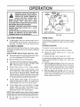
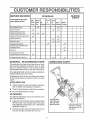
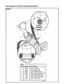
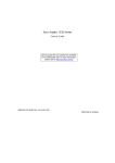
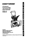
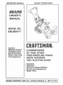
IMPORTANT
MANUAL
DO NOT THROW A WAY
MODEL NO.
536°885471
Caution:
Read and Follow
All Safety Rules
and instructions
Before Operating
This Equipment
5 HORSEPOWER
24" DUAL STAGE
FREE=WHEELING
]'RACK
SNOW THROWER
120V. ELECTRIC START
•
o
o
o
o
Assembly
Operation
Customer Responsibilities
Service and Adjustments
Repair Parts
SEARS, ROEBUCK AND CO., Hoffman
Estates,
IL 60179 U.S.A.
SAFETY
&
RULES
CAUTION:
ALWAYS
DISCONNECT
SPARK
PLUG WIRE AND
PLACE
WIRE WHERE
IT CANNOT
CONTACT
SPARK
PLUG
TO PREVENT
ACCIDENTAL
STARTING
WHEN
SETTING-UP,
TRANSPORTING,
ADJUSTING
OR MAKING REPAIRS
A
IMPORTANT
SAFETY STANDARDS
REQUIRE OPERATOR
PRESENCE
CONTROLS
TO MINIMIZE
THE
RISK OF INJURY. YOUR SNOW THROWER IS EQUIPPED WITH SUCH CONTROLS.
DO NOT
ATTEMPT TO DEFEAT THE FUNCTION OF THE OPERATOR PRESENCE CONTROL UNDER
ANY CIRCUMSTANCES
TRAINING
&
Read the operator's
manual carefully_ Be
thoroughly familiar with the controls and the
proper use of the snow thrower. Know how to
stop the snow thrower and disengage the
controls quickly.
1.
7_ Never attempt to make any adjustments while the
engine
(motor)
is running
(except
when
specifically recommended by the manufacturer).
8.
Never allow children to operate the snow thrower'
and keep them away while it is operating. Never
allow adults to operate the snow thrower without
proper instruction. Do not carry passengers.
2_
.
4.
Keep the area of operation clear of all persons,
particularly small children, and pet&
Exercise caution to avoid slipping or falling,
especially when operating in reverse.
2.
OPERATION
1.
Thoroughly
inspect the area where the snow
thrower Is to be used and remove all doormats,
sleds, boards, wires, and other foreign objects+
Disengage all clutches and shift into neutral
before starting the engine (motor')+
After striking a foreign object, stop the engine
(motor), remove the wire from the spark plug,
disconnect
the cord on electric
motors,
thoroughly inspect the snow thrower for any
damage, and repair the damage before restarting
and operating the snow thrower_
3_
Handle fuel with care; it is highly flammable.
(a) Use an approved fuel container.
If the snow
4_
(b) Never remove fuel tank cap or add fuel to a
running engine or hot engine.
and wipe up
(e) Never store fuel or snow thrower with fuel in
thetank inside of a building where fumes may
reach an open flame or spark_
5.
should
start
to vibrate
Stop the engine (motor) whenever you leave the
operating position, before unclogging the auger/
impeller housing or discharge guide, and when
making any repairs, adjustments, or inspection&
5.
(f)
thrower
abnormally,
stop the (motor)
and check
Immediately
for the cause_ Vibration is generally
a warning of trouble.
(c) Fill fuel tank outdoors with extreme care.
Never fill fuel tank indoors+
(d) Replace fuel tank cap securely
spilled fuel+
Do not put hands or feet near or under rotating
parts= Keep clear of the discharge opening at all
times,
2o Exercise extreme caution when operating on or
crossing gravel drives, walks, or roads. Stay alert
for hidden hazards or traffic_
3+ Do not operatethe snowthrower without wearing
adequate winter outer garments+ Wear footwear
that will improve footing on slippery surfaces+
4.
Let engine (motor) and snow thrower adjust to
outdoor temperatures
before starting to clear
snow=
Always wear safety glasses or eye shields during
operation or while performing an adjustment or
repair to protect eyes from foreign objects that
may be thrown from the snow thrower
9=
PREPARATION
1.
Adjust the snow thrower height to clear gravel or
crushed rock surfaces
,
Check fuel supply before each use, allowing
space for expansion as the heat of the engine
(motor) and/or sun can cause fuel to expand.
7_
Use extension co rds and receptacles as specified
by the manufacturer for all snow throwers with
electric drive motors or electric starting motor&
2
When cleaning, repairing, or inspecting,
make
certain the auger/impeller and all moving parts
have stopped. Disconnect the spark plug wire
and keep the wire away from the plug to prevent
accidental starting.
Take all possible precautions when leaving the
snow thrower unattended_ Disengage the auger/
impeller,
shift to neutral, stop engine, and
remove key.
SAFETY
8,
9.
Do not run the engine indoors, except when starting
the engine and for transporting the snow thrower in
or out of the building. Open the outside doors;
exhaust fumesaredangerous(containing CARBON
MONOXIDE, an ODORLESS and DEADLY GAS).
DO not clear snow across the face of slopes
Exercise caution when changing direction on
slopes. DO not attempt to clear steep slopes,
10. Never operate the snow thrower without proper
guards, plates or other safety protective devices
in place.
11. Never operate the snow thrower near glass
enclosures,
automobiles,
window
wells,
drop-offs, and the like wit hout proper adjustment
of the snow discharge angle. Keep children and
pets away.
12. Do not overload the machine capacity
attempting to clear snow at too fast a rate°
MAINTENANCE
or allow
15o Disengage power to the auger/impeller when
snow thrower is transported or not in use.
16. Use only attachments and accessories approved
by the manufacturer of the snow thrower (such
as tire chains, electric start kits, etc,),
AND STORAGE
Check shear bolts and other bolts at frequent
improper tightness to be sure the snow thrower
is in safe working condition_
2_ Never store the snow thrower with fuel in the fuel
tank inside a building where ignition sources are
present such as hot water and space heaters,
clothes dryers, and the like. Allow the engine to
cool before storing in any enclosure
3o Always refer to operator's manual instructions
for important details If the snow thrower is to be
stored for an extended period°
4.
Maintain or replace safety and instruction labels,
as necessary,
Run the snow thrower
a few minutes after
throwing snow to prevent freeze-up of the auger/
impeller.
5.
by
13. Neveroperatethe snowthrowerat high transport
speeds on slippery surfaces. Look behind and
use care when backing
14. Never direct discharge at bystanders
anyone in front of the snow thrower
RULES
WARNING
This snow thrower is for use on sidewalks,
driveways, and other ground level surfaces.
CAUTION should be exercised while using on
steep sloping surfaces. DO NOT USE SNOW
THROWER ON SURFACES ABOVE GROUND
LEVEL such as roofs of residences, garages,
porches or other such structures or buildings.
17. Never operate the snow thrower without good
visibility or light. Always be sure of your footing,
and keep a firm hold on the handles. Walk; never
run,
LOOK FOR THIS SYMBOL
A
DISCHARGE
CHUTE!
TO POINT OUT
IMPORTANT SAFETY PRECAUTIONS.
MEANS--ATTENTIONH!
BECOME ALERT!!!IT
YOUR SAFETY IS INVOLVED
PRODUCT SPECIFICATIONS
CONGRATULATIONS
on your purchase of a Sears
Craftsman Snow Thrower It has been designed, engineered and manufactured to give you the best possible
dependability and performance
Should you experience any problem you cannot easily
remedy, please contact your nearest Sears Service
Center/Department
We have competent, wel!-trained
technicians and the proper tools to service or repair this
unit
Please read and retain this manual The instructions will
HORSE
POWER:
DISPLACEMENT:
5hp
10.49
cu, in.
GASOLINE
CAPACITY:
enable you to assemble and maintain your snow thrower
properly Always observe the "SAFETY RULES."
MODEL
NUMBER 536 885471
SERIAL
NUMBER
DATE OF
PURCHASE
OIL (21 oz. Capacity):
5W30
SPARK
Champion
RJ19LM
PLUG :
(GAP .030 in.)
I VALVE
THE MODEL AND SERIAL NUMBERS WILL BE
FOUND ON A DECAL ATTACHED TO THE REAR
OF THE SNOW THROWER HOUSING
2 quart
Unleaded
CLEARANCE:
Intake: .010 In,
Exhaust:
.010 In.
YOU SHOULD RECORD BOTH SERIAL NUMBER
AND DATE OF PURCHASE AND KEEP IN A SAFE
PLACE FOR FUTURE REFERENCE
MAINTENANCE AGREEMENT
A Sears Maintenance Agreement is available on this
product Contact your nearest Sears Store for details
CUSTOMER
e
e
e
RESPONSIBILiTiES
Read and observe the safety rules
Follow a regular schedule in maintaining, caring for and using your snow thrower
Follow the instructions under "Customer Responsibilities" and "Storage" sections of this owner's manual
TWO YEAR UMITED WARRANTY ON CRAFTSMAN
SNOW THROWER
For two years from the date of purchase, when this Craftsman Snow Thrower is maintained, lubricated
and tuned-up according to the instructions in the owner's manual, Sears will repair, free of charge, any
defect in material and workmanship
If this Craftsman Snow Thrower is used for commercial or rental purposes, this warranty applies for only
90 days from the date of purchase
This warranty does not cover the following:
• Expendable items which become worn during normal use, such as spark plugs, drive belts and shear
pins
o Repairs necessary because of operator abuse or negligence, including bent crankshafts and the failure
to maintain the equipment according to the instructionscontained in the owner's manual
WARRANTY SERVICE IS AVAILABLE BY RETURNING THE CRAFTSMAN SNOW THROWER TO THE
NEAREST SEARS SERVICE CENTER/DEPARTMENT
IN THE UNITED STATES THIS WARRANTY
APPLIES ONLY WHILE THIS PRODUCT IS IN USE IN THE UNITED STATES
This warranty gives you specific legal rights, and you may also have other rights which may vary from
state to state
SEARS, ROEBUCK AND CO Department D/817WA, Hoffman Estates, IL 60179
4
TABLE OF CONTENTS
SERVICE AND ADJUSTMENTS
STORAGE ...........................
TROUBLE SHOOTING .....................
REPAIR PARTS (SNOW THROWER)
REPAIR PARTS (ENGINE)
.....
PARTS OR, DERING/SERVlCE
SAFETY RULES .......................................
2,3
PRODUCT SPECIFICATIONS
..................... 4
CUSTOMER
RESPONSIBILITIES
.......4,17-19
WARRANTY ........................................................... 4
TABLE OF CONTENTS
..............................
5
INDEX ...............................................
5
ASSEMBLY ....................................................... 6-9
OPERATION .......................................
10-1 6
19-26
27
28
29-39
40-43
44
INDEX
A
Adjustment:
Auger
.....................
21
Belt ....................
21
Belt Guide
...........
23
Cable
...........................
21
Carburetor .....................
26,27
Friction Wheel ..............
23
Spark Plug .......................
26
Track ................................
25
Traction and Auger ........
21
Assembly:
Crank Assembly ..........
8
Shifter Lever ....................................... 9
Skid Height Adjustment ........
7,29
Unpacking .......................
7
B
Belts:
Adjust Belts ...........
21
Belt Guide Adjustment ..........
23
Replace Belts .....................
22,23
C
Cables, Clutch ......................
7, 9, 21
Carburetor: ............................
26, 27
Choke .........................
10, 11, 14,15
Clutch, Levers ............................ 10, 11
Controls:
Engine .................
10. 11, 13, 14,15
Snow Thrower
.......
10
Crank:
Adjusting Rod ..........
8
Assembly ...............
8
Operation .....................
t1
Customer Responsibilities
4.17-19
Agreement ...................
4
Auger Gear Box .......................
19
Auger Shaft ...........................
18
Engine .........................................
18
General Recommendations ....
17
Hex Shaft and Gears .........
19
Spark Plug .......................
19
Weight Transfer System ....
18
D
Drive, Auger ...........
Drive, Traction ............
Deflector, Snow Chute
11
1t
11
E
Engine:
Control
....
10, 11, 13, 14,15
Oil Cap ..........
13,19
Oil Change ..............
19
Oil Level
Oil Type
Speed Governor
Starting
Electric
Recoi
Storage
t3, 19
4. !3. 19
26
14.15
14
15
27
F
Free-Whee Tract,.
Fuel, Type
Fuel, Storage.
Friction Wheel:
Adjuslmen_
Replacemen;
12
4. 13
13.26
.
G
Gears:
Auger Gear Box
Hex Shaft
23
24
19
19
H
Handle Upper ana Lower
. .8
Height Adjust Skids
7.20
Hex Shaft
19
I
Ignition, Key
10. 11 13. 14.15
Index
5
L
Levers:
Auger Drive Clutch
7.9.10. 11.2"
Choke
10 11 13. 14.15
Shifter
g. 10
ThrottleContro
.10 11.13.!4.15
Traction Drive Cfutcll 7.9. 10. 11.21
L Jbdcation:
Auger Gear Box
19
Auger Shaft
19
Chart
.
17
Disc Drive Plate
18
Engine
13 19
Hex Shaft and Gears
19
Weight Transfer St s_err
15.18
O
Oil:
Engine
............
4, 13, 19
Extreme Cold Weather .......... 13,19
Storage ...............
27
Type ....
4, 13, 19
Operation:
Engine Controls
!0.11, 13,14,15
Free-Wheel. Track
..........
12
Operating Snow Thrower ...........
..................
11, 12, 14,15
Operating Tips ...........
16
5
Starting the Engine
14.15
Electric
14
Recoil .....
15
Snow Thrower Controls
10-12
Weight Transfer Syslem
12
P
Parts .........
29-43
Primer Button
.. 10. 11 13.14, t5
R
RepaidReplacement
Paris
29-43
Replacements:
Auger Shear Bolt
25
Belts ............
22.23
Friction Wheel
24
Safety Rules .......
Service and Adjustments:
Auger Housing Height
Auger Shear Bolt
Belts ....
Beit Guide
Belt Replacements
Cable
Carburetor
Friction Wheel
Spark Plug
Track ........
Spark Plug
Specifications
Speed Governor
Starting time Engine
Stopping the Engine
Stopping the Snow Throwe_
Shipping Carton
Skid Height
Shifter Lever
Shear Bolts
Storage
__
Table of Contents.
Trouble Shooting ChaT1
Tools for Assembly
Traction Drive Bell
Track Adjustment
..
W
Warranty
,
Weight Transfer System
2.3
7.20
25
21 _23
23
21-23
7, 9.21
26, 27
23.24
26
25
19.26
.4
26
14,15
11 14 15
11
6, 7
7 20
9-10
25
27
5
28
6
21 23
25
4
12 18
CONTENTS OF HARDWARE
CONTENTS
OF PARTS
PACK
BAG
"2 - Spare Spacers
"2 - Spare Shear Bolts
(1/4-20 x 1-3/4 In )
"2 - Spare 1/4_20Hex Nuts
m
1 - Owner's manual
1 - Knob with Threads
"Non-Assembly
Parts packed
1 -Starter
Motor Cord
Parts
separately
I
I
I
I
I
I
--m
in carton (not shown
1-
container
5W30 oil
full size)
2 - Ignition
Keys (Attached
to engine in plastic bag)
1 - Parts Bag
1 - Crank
Assembly
THiS SNOW THROWER HAS A TRACK DRIVE SYSTEM
YOU FREE-WHEELING
CAPABILITY
EQUIPPED
TO GIVE
If your snow thrower must be moved without the aid of the engine, it will be easier to pull the snow thrower
backward by the handles, rather than pushing For details on how to use the free-wheeling capability, see the
Track Drive/Free-Wheel Feature paragraph in the Operation section of this manual
On start up, the track drive system may be tight but will loosen up as the snow thrower is used After first use, check the
track for tension and adjust if necessary
See the Track Adjustment
paragraph
in the Service and
Adjustments section of this manual Check track adjustment and fasteners regularly
6
ASSEMBLY
TOOLS
REQUIRED
LOWER
FOR ASSEMBLY
ANDLE
CONTRO_PANEL
i
I 22211-
t
Knife (to cut carton and plastic ties)
1/2 inch wrenches (or adjustable wrenches)
9/16 inch wrenches (or adjustable wrenches)
3/4 inch wrenches (or adjustable wrenches)
Pliers (to spread cotter pin)
Screwdriver
CLUTCH
1 - Measuring tape or ruler
UPPER
HANDLE
ASSEMBLY
Figure I shows the snow thrower in the shipping position
Figure 2 shows the snowthrower completely assembled
FIG. 1
Reference to the right and left hand side of the snow
thrower is from the operator's position at the handle
LEVER
TO REMOVE SNOW THROWER
FROM CARTON (See Fig. 1)
CRANK
@
Locate and remove container of 5W30 oil
e
Locate the crank assembly and place the assembly
aside
O
Remove and discard the packing material lrom
around the snow thrower
O
Cut all four corners of the carton from top to bottom
and lay the panels flat
ASSEMBLY
@ Roll the snowthrower off the carton by pulling on the
lower handle CAtJTION: DO NOT back over cables
@
Remove the packing material from the upper and
lower handle assembly
@ Cut ties securing the clutch control cables to the lower
handle and lay cables back away Irom the motor
frame
FIG, 2
NOTE: The drive system may be tight when you first use
your snow thrower, It loosens up as you use it
@ To complete upper handle installation and install
chute crank assembly, see To Install The Upper
Handle and Crank Assembly paragraph on page 8
NOTE: If the cables have become disconnected from the
clutch levers, reinstall the cables as shown in Fig 3 and
3A
4" LG FREE
STATE
/
TRACTION
DRIVE\
3" LG FREE
STATE
\
_
/
_
sP°,NO
\
DR,VE
SPR,N t-.
DRIVE
LEVER
"Z" FITI'ING
/
--"
LEVE.
FIG, 3A
,'_
//
AUGER
/DRIVE
;pR,NO
/ y_j DR,VE
;P,,NG
CASLE
FIG. 3
CAUTION:
IF YOU
ARE
REMOVING
SNOW
FROM
ANY ROCKY
OR UNEVEN
SURFACE,
RAISE
THE FRONT
OF THE
SNOW THROWER
BY MOVING THE
SKIDS DOWN. THIS WILL HELP TO PREVENT
ROCKS AND OTHER DEBRIS FROM BEING
PICKED UP AND THROWN BY THE AUGER
ASSE
LY
HOW TO SET UP YOUR SNOW
THROWER
O
Your snow thrower is equipped with
skids (See Fig 2) on the outside
housing To adjust the skid height
conditions, see To Adjust Skid Height
page 18
UPPER
height adjust
of the auger
for different
paragraph on
11/32'
5/16" HEX
BLACK
CAP
TO INSTALL THE UPPER HANDLE
AND CRANK ASSEMBLY
@
o
Replace the right hand screw, flatwasher, Iockwasher,
and hex nut through the handle arrd shifter plate Do
not tighten until all bolts are in place
'SHIFTER
PLATE
FIGo 4A
UPPER
HANDLE
@ Loosen, but do not remove, the screws, flatwashers,
Iockwashers, and hex nuts in the upper holes of the
lower handle
Raise upper handle into operating position Upper
handle should be to the outside of the lower handle
arrd shitter plate to the inside
16 X 2-3/4
BOLT
5/16"
LOCKWASHER
Remove the screws, fiatwashers, Iockwashers, and
hex nuts securing the shifter plate in the lower holes
of the lower handle and move shift lever to 3rd gear
(See Fig 4A)
o
ADJUST NUTS TO
MOVE EYE BOLT IN
OUT
_
"'4
EYE
NOTE: Unless you have the assistance of another person, it may be easier to install one side of the handle at a
time
@
O
O
Tighten nut on eye bolt installed earlier, keeping eye
in line with the rod while tightening the inside securely
e
Carefully remove cotter pin, clevis pin and drilled pin
from yoke end of crank rod assembly
O
Place universal joint into end of worm gear lining up
large holes Insert drilled pin (ensure opening in pin
is in line with small openings in universal joint)
O
Place yoke end of crank rod around universal joint,
lining up openings, Insert clevis pin through assembly and secure with cotter pin Spread ends of cotter
pin to lock in place
Tighten the screw, flatwasher, Iockwasher arrd hex
nut at the lower right hand hole (See Fig 4A)
NOTE: Make sure the cables are not caught between the
upper and lower handle
O Tighten two upper handle bolts
3/8"
FLATWASHER
BOOT
ADAPTER
3/8"
FLATWASHER
FIG. 4B
Install eye bolt through lower hole in the left hand side
of the handle and shifter plate (See Fig 4B)
install the 3/8" fiatwasher and the 3/8" nylon Iocknut
loosely on the eye bolt as shown in FIG 4B
o
CLON
LOCKNUT
Remove the 3/8" nylon Iocknut and flatwasher from
the eye bolt assembly (on the chute crank assembly
removed earlier) Check to make sure the two 3/8"
jam nuts are tight The jam nuts should be 2 75 inches
from the end of the eye bolt (See Fig 4B)
O
FLATWASHEB
i
CLEVIS
PIN
TER PIN
UNllVERSAL
JOINT
CRANK ROD
ASSEMBLY
DRILLED
PIN
FIG. 5
O
Check chute crank rod assembly for proper operation Rotate the chute crank fully clockwise and fully
counter-clockwise
Discharge chute should rotate
fully to the left and fully to the right without tile chute
crank binding
NOTE: Be sure the crank does not touch the side of the
engine orthe cover will be scratched
ASS
LY
TO INSTALLSHIFTER LEVER KNOB
AUGER CLUTCH
LEVER
TRACTION CLUTCH
LEVER
@ Thread the shifter lever knob onto the threaded end
of the shifter lever until it is snug against the hex nut
and the lip is pointed toward the engine Tighten the
hex nut against the bottom of the shift lever knob (See
Fig 6 )
OFF
SHIFT R KNOB
\
ON
ON
NUT
"SHIFTER
LEVER
CONTROLCABLRS
FIG. 7
,# CHECKLIST
FIG, 6
TO CHECK/ADJUST
CONTROL CABLES
CLUTCH
BEFORE
YOU OPERATE
AND ENJOY
YOUR NEW
SNOW THROWER, WE WISH TO ASSURE THAT YOU
RECEIVE
THE
BEST
PERFORMANCE
AND
SATISFACTION FROM THIS QUALITY PRODUCT
PLEASE REVIEW THE FOLLOWING
CHECKLIST
The control cables, Fig 7, attached to the auger clutch
lever and traction clutch lever may need to be adjusted
before you use your snow thrower
,(
All assembly instructions have been completed
,/
The discharge chute rotates freely
,/
No remaining loose parts in carton
For instructions on checking or adjusting the control
cables, see To Adjust Clutch Conlrol Cables paragraph on
page 21
WHILE
LEARNING
HOW
TO USE YOUR SNOW
THROWER,
PAY
EXTRA
ATTENTION
TO THE
FOLLOWING IMPORTANT ITEMS
€',/
Engine oil is at proper level
7,/" Make sure gas tank is filled properly
unleaded gasoline
,/,f
Become
function
familiar
wilh clean
with afl controls-their
location
Operate controls before starting engine
fresh
and
m
OPERATION
KNOW YOUR SNOW THROWER
READ THIS OWNER'S
MANUAL AND SAFETY RULES BEFORE OPERATING
YOUR SNOW
THROWER,. Compare the illustrations with your snow thrower to familiarize yourself with the location of various
controls and adjustments
AUGER
Save this manual for future reference
DRIVE
LEVER
TRACTIONDRIVE
PRIMERBUTTON
STARTER
CRANK
ASSEMBLY
CHUTE
DEFLECTOR
SPEED
IL
STARTER
HANDLE
LEVER
WEIGHT
CHuTIHOKECON_
PEDAL
HEIGHT ADJUST
SKIDS
FIG. 8
SEARS FREE-WHEELING
SNOW THROWERS conform to the safety standards of the American National
Standards Institute B71 3-1984
AUGER DRIVE LEVER - Starts and stops the auger and
impeller (snow gathering and throwing)
TRACTION DRIVE LEVER - Propels the snow thrower
forward and in reverse
SPEED SHIFTER LEVER- Selects the speed of the snow
thrower (6 speeds forward and 2 speeds reverse)
CRANK ASSEMBLY - Changes the direction of snow
throwing through the discharge chute
CHUTE DEFLECTOR - Changes the distance the
snow is thrown
DISCHARGE CHUTE - Changes the height arrd direction
the snow is thrown,
KLICK PIN - Changes the track drive from normal to freewheel drive, which allows the unit to be transported easily
without the engine being started
WEIGHT TRANSFER PEDAL - When engaged (by lifting
up on the upper handle) it helps keep the snow thrower in
contact with the ground, and reduces ride up on ice and
hard-packed snow When released (by pushing down on
weight transfer pedal with the ball of your foot), it eases
steering of the snow thrower
HEIGHT ADJUST SKIDS - Adjusts the ground cIearance
of the auger housing
IGNITION KEY - Must be inserted to start the engine
RECOIL STARTER HANDLE - Starts the engine manually
CHOKE CONTROL - Used to start a cold engine
PRIM ER BUTTON - Injects fuel directly into the carburetor
manifold for fast starts in cold weather
THROTTLE CONTROL - Controls the engine speed
ELECTRIC STARTER BUTTON- Used to start tile engine
using the 120 V electric starter
OPERATnON
The operation of any snow thrower can result in foreign objects being thrown into the
eyes, which can result in severe eye damage Always wear safety glasses or eye
shields while operating the snow thrower
We recommend standard safety glasses available at SEARS Retail Store or Service
Center
HOW TO USE YOUR SNOW
THROWER
WING KNOB
TO STOP YOUR SNOW THROWER
@ To stop throwing snow, release the auger drive
lever (See Fig 11)
@ To stopthe track, release the traction drive lever (See
Fig 11)
¢
FIG. 9
To stop the engine, push the throttle control lever to
off and pull out the ignition key (See Fig 10)
NOTE: DO NOT turn key,
TO CONTROL
SNOW
DISCHARGE
@ Turn the crank assembly to set the direction
snow throwing
of the
@ Loosen the wing knob on the chute deflector and
move the deflector to set the distance Move the
deflector UP for more distance, DOWN for less distance Then tighten the wing knob (Fig 9)
TO MOVE
FORWARD
AND
BACKWARD
CHOKE
CONTROL
@ Toshift, releasethetractiondriveleverandmove
the
speed shifter lever to the speed you desire Ground
speed is determined by snow conditions
FIGo 10
@ Select the speed you desire by moving the speed
shifter lever into the appropriate
area on the
control panel
Speeds 1,2 - Wet, Heavy, Extra Deep
STARTER
HANDLE
THROTTLE
CONTROL
TRACTION DRIVE
LEVER
AUGER
DRIVE
OFF,__
Speed 3 - Moderate
Speed 4, 5 - Very Light
Speed 6 - Transport only
@ Engage the traction drive lever (See Fig 11, left
hand) As the snow thrower starts to move, maintain
a firm hold on the handles, and guide the snow
thrower along the clearing path Do not attempt to
push the snow thrower
@ To move the snow thrower backward, move the
speed shifter lever into first or second reverse and
engage the traction drive lever (left hand)
IMPORTANT:
TO THROW
0
NEVER MOVE THE SPEED SHIFTER
LEVER WHILE THE TRACTION LEVER IS DOWN
SNOW
Push down the auger drive lever (See Fig 11, right
hand)
@ Release to stop throwing snow
_]
DN :_
ON
T;21"22
RIGHT
HAND
LEFT
HAND
FIGo11
CAUTION: READ OWNER'S MANUAL
BEFORE
OPERATING
MACHINE,
NEVER DIRECT DISCHARGE TOWARD
BYSTANDERS. STOP THE ENGINE BEFORE UNCLOGGING
DISCHARGE
CHUTE OR AUGER HOUSING AND BEFORE LEAVING THE MACHINE,
OPERATION
TO USE WEIGHT
TRANSFER
SYSTEM
UPPER HANDLE
In hard packed or heavy snow conditions, conventional
snow throwers tend to ride up and leave uneven mounds
of snow behind For these conditions, your new tracked
snow thrower has a unique weight transfer system (See
Fig 12) designed to minimize ride-up
(Lift up here) '
The weight transfer system engaged shifts more weight
to the auger housing This weight transfer keeps the
snow thrower in contact with the ground and reduces
ride-up on ice and snow
In lighter snow conditions or when transporting, you
should release the weight transfer system for easier
steering
O
O
To use the weight transfer system, lift up on upper
handle until bracket bolts snap into place in upper
slots of weight transfer pedal
WEIGHT TRANSFER
PEDAL UPPER SLOT
To release, hold upper handle firmly and push down
on the weight transfer pedal with the ball of your foot
NOTE: The weight transfer system will not work if the
auger housing height adjust skids are adjusted to the
highest position
TRACK
DRIVE/FREE-WHEEL
FEATURE
FIG.12
DRIVE WHEEL
FREE WHEEL
The track system on your snow thrower has a drive/freewheel feature (See Fig 12A) which allows the u nit to be
transpoded easily without the engine being started
O
To use free-wheeling, lift up the loop of the klick pin
inthe fronttrack wheel and pullthe pin out Installthe
pin through the hole in the shaft outside of the track
wheel Repeat on the opposite side of the unit
O
To use normal drive, lift the loop of the klick pin from
the outside hole in the shaft Rotate the front track
wheel until the hole in the track wheel hub and the
outside hole in the shaft are in-line Place pin through
the hole inthetrack hub Repeat on the opposite side
of the unit
NOTE: If unit does not move when engine is started,
check the pin locations Pins on both sides of unit should
be in the normal drive position for unit to move
KLIC
I
FIG.12A
O ERATBON
BEFORE
FILL
STARTING
THE ENGINE
WARNING: Experience indicates that alcohol blended
fuels (called gasohol or those using ethanol or methanol)
can attract moisture which leads to separation and formation of acids during storage Acidic gas can damage the
fuel system of an engine while in storage
OIL:
This snow thrower was shipped with a container of 5W30
motor oil. This oil must be added to the engine before
operating Remove the oiltill cap/dipstick and fill the crank
case to FULL line on dipstick (21 ounces) (See Fig 13)
NOTE: Engine may already contain some residual oil
Check frequently when filling the crankcase_ Do not
over-fill.
Tighten the fill cap/dipstick securely each time you check
the oil level,
NOTE: Oil must be changed after the first 2 hours of
operation to extend engine life
For extreme cold operating conditions of O°F and below.
use a partial synthetic OW30 motor oil for easier starting
To avoid engine problems, the fuel system should be
emptied before storage for 30 days or longer Start the
engine and let it run until the fuel lines and carburetor are
empty Use the carburetor bowl drain to empty residual
gasoline from the float chamber (Fig 39) Use fresh fuel
next season (See Storage instructions on page 27 for
additional information )
Never use engine or carburetor cleaner products in the
fuel tank or permanent damage may occur
OIL FILL CAP/DIPSTICK
_
AND
CAUTION
MUST BE
USED WHEN
AUTION:
GASOLINE
IS FLAMMABLE
HANDLING OR STORING IT
DO NOT FILL FUEL TANK WHILE SNOW
THROWER IS RUNNING, WHEN IT IS HOT, OR
WHEN SNOW THROWER IS IN AN ENCLOSED
AREA.
KEEP AWAY FROM OPEN FLAME OR AN ELECTRICAL SPARK AND DO NOT SMOKE WHILE
FILLING THE FUEL TANK.
AND ADD MARK
NEVER FILL THE TANK COMPLETELY.
FILL
THE TANK TO WITHIN 1/4"- 1/2" FROMTHE TOP
TO PROVIDE SPACE FOR EXPANSION OF FUEL
FIG.13
ALWAYS FILL FUEL TANK OUTDOORS AND
USE A FUNNEL OR SPOUT TO PREVENT SPILL°
ING.
FILL GAS:
Fill the fuel tank with clean, fresh, unleaded grade automotive gasoline Be sure that the container you pour the
gasoline from is clean and free from rust or other foreign
particles Never use gasoline that may be stale from long
periods of storage in the container
MAKE SURE TO WIPE UP ANY SPILLED FUEL
BEFORE STARTING THE ENGINE
STORE GASOLINE IN A CLEAN, APPROVED
CONTAINER AND KEEP THE CAP IN PLACE ON
THE CONTAINER.
NOTE: S,AE, 5W-30 motor oil may be used to make
starting easier in areas where the temperature is 20 ° F
or lower
13
OPERATION
TO STOP ENGINE
e
CHOKE
CONTROL
To stop engine, move the throttle control lever to
STOP position and remove key Keep the key in a
safe place The engine will not start without the key
TO START ENG[NE (Electric
e
(Electric
IGNITION
KEY
start) (See Fig. 14)
THROTTLE
Move the throttle control to RUN position
e
Remove the keys from the plastic bag Insert one
key into the ignition slot Be sure it snaps into place
DO NOT TURN KEY Keep the second key in a safe
place
e
Rotate the choke knob to FULL choke position
O
Connect the power cord to the switch box on the
engine
CAUTION:
STARTER
IS
SHOCK, WHICH MAY BE INJURIOUS TO OPERATOR.,
FOLLOW ALL INSTRUCTIONS
CAREFULLY AS SET FORTH IN THE "TO START
ENGINE" SECTION. DETERMINE THAT YOUR
HOUSE WIRING IS A THREE-WIRE GROUNDED
SYSTEM. ASK A LICENSED ELECTRICIAN IF
YOU ARE NOT SURE IF YOUR HOUSE WIRE
SYSTEM IS NOT A THREE-WIRE SYSTEM, DO
NOT USE THIS ELECTRIC STARTER UNDER
ANY CONDITIONS.
IF YOUR SYSTEM IS
GROUNDED AND A THREE-HOLE
RECEPTACLE IS NOT AVAILABLE
AT THE POINT
YOUR STARTER WILL NORMALLY BE USED,
ONE SHOULD BE INSTALLED BY A LICENSED
ELECTRICIAN.
WHEN CONNECTING 120 VOLT AC POWER
CORD, ALWAYS CONNECT THE CORD TO
THE SWITCH BOX ON THE ENGINE FIRST,
THEN PLUG THE OTHER END INTO THE
THREE-HOLE GROUNDED RECEPTACLE.
WHEN DISCONNECTING POWER CORD, ALWAYS UNPLUG THE END IN THE THREE-HOLE
GROUNDED RECEPTACLE FIRST.
is above 50°F
Two times if temperature is 50°F to 15°F
Four times if temperature is below 15°F
Push down on the starter button until the engine
starts Do not crank for more than 10 seconds at a
time This electric starter is thermally protected If
overheated it will stop automatically and can be
restarted only when it has cooled to a safe temperature (a wait of about 5 to 10 minutes is required)
@ When the engine starts, release the starter button
and slowly rotate the choke to OFF position If the
engine falters, rotate the choke to FULL and then
gradually to OFF
Disconnect the power cord from the receptacle first
and then from the switch box on engine
NOTE: Allow the engine to warm up for a few minutes
because the engine will not develop full power until it
reaches operating temperature
e
THIS
POWER
CORD
ANDA PLUG
AND IS
EQUIPPED
WITH
THREE-WIRE
DESIGNED TO OPERATE ON 120
VOLT AC HOUSEHOLD CURRENT., IT MUST
BE PROPERLY GROUNDED AT ALL TIMES TO
AVOID THE POSSIBILITY
OF ELECTRICAL
Plug the other end of the power cord into a threehole, grounded 120 volt AC receptacle
Do not prirne if temperature
O
CONTROL
FIG.14
@ Push the primer button while coveringthe vent hole
as follows: (Remove finger from primer button between primes)
e
RECOIL
STARTER
Be sure the auger drive and traction drive levers are
in the disengaged RELEASED position
O
e
ELECTRIC
STARTER
BUTTON
Starter)
Be sure that the engine has sufficient oil The snow
thrower engine is equipped with a 120 volt A C electric
starter and recoil starter Before starting the engine, be
certain that you have read the following informalion:
COLD START
PRIMER
BUTI'ON
Run the engine at full throttle RUN when throwing
snow
14
0
ERATJON
CAUTION: NEVER RUN ENGINE IN-
PRIMER
BUTTON -_'J U_,_
CHOKE
VENTILATED
ENGINE
EXDOORS OR IN AREAS.
ENCLOSED,
POORLY
HAUST CONTAINS CARBON MONOXIDE, AN ODORLESS AND DEADLY GAS.
KEEP HANDS, FEETI HAIR AND LOOSE
CLOTHING AWAY FROM ANY MOVING PARTS
ON ENGINE AND SNOW THROWER.
WARNING: TEMPERATURE OF MUFFLER AND
NEARBY AREAS MAY EXCEED 150': F. AVOID
THESE AREAS.
DO NOTALLOW CHILDREN OR YOUNG TEENAGERS TO OPERATE OR BE NEAR SNOW
THROWER WHILE IT IS OPERATING.
IGNI_/I)
STARTER
KEY /
THROTTLE
HANDLE
CONTROL
FIG. 14A
TO STOP ENGINE
WARM
@ To stop engine, move the throttle control lever to
STOP position and remove key Keep tile key in a
safe place The engine will not start without the key
If restarting a warm engine after a short shutdown, rotate
choke to OFF instead of FULL and do not push Ihe primer
button
TO START ENGINE
FROZEN
Be sure that the engine has sufficient oil Before starting
the engine, be certain that you have read the following
information:
If the starter is frozen and will not turn engine,
COLD
@
@
@
START
(Recoil
Start)
(See Fig. 14A)
Be surethe augerdrive and the traction drive levers
are in the disengaged RELEASED position
o
Press the primer button in cold weather Press
two or three times, while keeping your finger over
the vent hole on the primer button Release finger
between primes Additional priming may be neces
sary for the first start if the temperature is below 15':'
F Do not prime if tem-perature is above 50 ° F
Pull the starter handle rapidly Do not allow the
handle to snap back, but allow it to rewind slowly
while keeping a firm hold on the starter handle
@
As the engine warms up and begins to operate
evenly, rotate the choke knob slowly to OFF
position If the engine falters, return to FULL choke,
then slowly move to OFF choke position
Pull as much rope out of the starter as possible
@
Release the starter handle and lel il snap back
against the starter
@ With the engine running, pull the starter rope hard
with a continuous full arm stroke three or four times
Pulling of starter rope will produce a loud clattering
sound This is not harmful to the engine or starter
to FULL choke position
@
e
If the engine still fails to start, repeat until it starts
Push the key into the ignition slot found in parts
page Be sure it snaps into place DO NOT TURN
KEY Place extra key in a safe place
Rotate choke control
STARTER
To help prevent possible freeze-up of recoil starter and
engine controls, proceed as follows after each snow
removal job
Move the throttle control to RUN position
e
START
@ With the engine not running, wipe all snow and
moisture from the carburetor cover in area of control
levers Also move throttle control, choke control and
starter handle several times
NOTE: Before using the snow thrower, allow the engine
to warm up for a few minutes because the engine will not
develop full power until it reaches operating temperature
@ Run the engine at or near the top speed when
throwing snow
15
OPERATIO
SNOW THROWING
o
TiPS
CAUTION:
For maximum snow thrower efficiency in removing
snow, adjust ground speed, NEVER the throttle Go
slower in deep, freezing or wet snow If the track
slips, reduce forward speed The engine is designed
to deliver maximum performance at full throttle and
should be run at this power setting at all times
A
@ Most efficient snow throwing is accomplished when
the snow is removed immediately after it falls
@
O
The snow should be discharged down wind whenever possible
O
For normal usage, set the skids so that the scraper
bar is 1/8" above the skids For extremely hardpacked snow surfaces, adjust the skids upward so
that the scraper bar touches the ground
o
On gravel or crushed rock surfaces, set the skids at
1-1/4" below the scraper bar (see To Adjust Skid
Height paragraph on page 20) Stones and gravel
must not be picked up and thrown by the machine
O
If the front of the snow thrower has a tendency to
raise, reduce the ground speed and engage the
weight transfer system
Clean the snow thrower thoroughly after each use
O
Remove ice and snow accumulation and all debris
from the entire snow thrower, and flush with water (if
possible) to remove all salt or other chemicals Wipe
snow thrower dry
DRIVE AND TRACTION
e MOVE THROTTLE
TION.
LEVER TO STOP POSI-
REMOVE (DO NOT TURN) IGNITION KEY
e DISCONNECT
SPARK PLUG WIRE
e DO NOT PLACE YOUR HANDS IN THE
AUGER OR DISCHARGE CHUTE USE A
PRY BAR,
@ After the snow throwing job has been completed,
allow the engine to idle for a few minutes, which will
melt snow and accumulated ice off the engine
O
LODGED
IN ITEM
AUGER
WITHOUT
TAKING
OVE ANY
THAT
MAY BECOME
THE FOLLOWING PRECAUTIONS:
e RELEASE AUGER
DRIVE LEVERS.
•
For complete snow removal, slightly overlap each
path previously taken Use more overlap in deep
snow to prevent overloading
DO NOT ATTEMPT TO RE-
16
SERVICE
RECORDS
,,,,,
Fill in dates as you complete regular service
SERVICE
DATES
SCHEDULE
,.,,,,,
,,,
,,,,,,
,,,,,,
,,,,,,
After
Before
Every
First 2 Each As
10
hours Use
Needed Hours
Every
25
Each
Before
Hours Seasor Storage
CheckEngineOil Level
Change Engine Oil
ALlScrewsand Nuts
CheckTractionClutchCable
Tighten
Adjustment
(See Cable Adjustment)
Replace Spark Plug
Adjust
DriveBelts
!t
LubricateAll PivotPoints
Lubricate Auger Shaft (See
,
Shear
BoltReplacement)
DrainFuel
Check Auger
Adjustment
ClutchCable
(See Cable Adjustment)
Lubricate Disc Drive Plate Zerk
GENERAL
v"
RECOMMENDATIONS
LUBRICATION
i,,
The warranty on this snow thrower does not cover items
that have been subjected to operator abuse or negligence, To receive full value from the warranty, operator
must maintain snow thrower as instructed in this manual
,
t
i
i
,
CHART
t
,i
,,,i
Some adjustments will need to be made periodically to
properly maintain your snow thrower
All adjustments in the Service and Adjustments section
of this manual should be checked at least once each
season,
AFTER
FIRST USE
O
Check the tracks for tension and adjust if necessary
(See To Adjust Track paragraph on page 25)
e
Check the track adjustment and fasteners regularly
e
Be sure that all fasteners are tight
AS REQUIRED
The following adjustments
than once each season
e
G
should be performed more
Lubricate Disc
Drive Plate zerk
with a HI-Temp
Moty EP grease,
Auger and Track Drive Belts should be adjusted alter
the first 2 hours of use and again alter 25 hours and
at the beginning of each season See To Adjust Belts
paragraph on page 21
All screws and nuts should be checked oftento make
sure they are tight, preferably after each use
17
Lubricate auger shaft,
Coat with a clinging
type grease such as
Lubriplate
AFTSMAN
24" SNOW THROWER
,,
'H
lIVE COMPONENTS
536.885471
I,,
REPAIR
PARTS
2
4O
15
8
10
42
26
tEE
,IO.
1
2
3
4
5
6
7
8
9
10
11
12
13
14
15
16
17
18
19
20
21
22
PART NO,
579941
313853
137185
313919
579937
11871
1502
583164
583206
583155
85501
73812
73811
580969
49562
580970
580961
580965
1084
120380
180020
334163
PART NAME
Lever Assembly, Traction Clutch
Bearing, Flange
Pin, Cotter
Spring, Return
Lever, Spring Traction Clutch
Screw, HHC, 1/4-20 x 5/8 In
Nut, Hex, 1/4-20 Thd
Disc, Friction Wheel, 7"
Zerk Grease
Shaft, Hex Traction
Bearing Assembly, Trunion
Flatwasher, 50 x 1 00 x .06
Ring, Retainer
Flatwasher, .680 x 112 x 06
Bearing, Roller
Key, Square
Pulley, Traction Drive
Wave Washer
Flatwasher, 281x1.00x.063
Lockwasher, Split 26 x 50 x 06
Screw, HHC, 1/4-20 x 5/8 In
Bearing & Retainer Assembly ..
REF,
NO.
PART NO.
23
24
25
26
27
28
29
30
31
32
33
34
35
36
37
38
39
40
41
42
43
44
35497
120638
579858
331112
73811
85501
73812
581773
313883
11871
120380
120375
579858
334163
35497
120638
334163
35497
579893
334163
35497
579867
PART NAME
Screw, WaTap, 5/16-18 x 1/2 In
Lockwasher, Split, 31 x .58 x 08
Washer, Special
Shaft Hex & Sprocket Assembly
Retaining Ring
Bearing, Trunion
Flatwasher, _505xl 00x 06
Hub, Friction Wheel
Wheel, Friction Disc
Screw, 1/4-20x.63
Washer, Regsptlk 263x 49x 07
Nut, 1/4-20 Reghex
Washer, Sp 502x 75x 0605
Bearing & Retainer Assy
Screw, WaTap, 5/16-18xl 2 In
Lockwasher, Split 31x58x 08
Bearing & Retainer Assy
Screw, WaTap, 51/6-18xl/2 In
Sprocket, 8 Tooth, Assembly
Bearing & Retainer Assy
Screw, WaTap 5/16-18xl/2 In
Chain, Roller #42
313995E
,,,,,,
CRAFTSMAN
RER.
NO. PART NO.
1
2
3
4
5
6
7
8
9
10
10577
10576
180020
46931
303008
9344
9566
50304
9346
581389
24" SNOW THROWER
PART NAME
Case, Gear Box R H
Case, Gear Box L H
Screw, HHC, 1/4-20x3/4 In
Locknut, Wd FI, 5/16-24 Thd
Nut, Hex Keps, 1/4-20 Thd
Screw, WaTap, 3/8-16xl/2 In,
Seal, Oil
Bearing, Flange
Flatwasher, 752xl 24x09
Shaft, Auger, 24 In
536.885471
RE]-,
NO.
11
12
13
14
15
16
17
18
19
PART NO.
51279
51405
431787
5O221
583125
580295
454565
313828
585598-830
PART NAME
Gasket, Gear Case
Gear, Worm
Key, Woodruff #61
Bearing, Flange
Shaft, Worm impeller
Collar, Thrust
Pin, Spring
Bearing, Roll
Impeller Assembly
313996,_
CRAFTSMAN
24" SNOW THROWER
AUGER HOUSING
.14
536.884571
REPAIR PARTS
75
///'_!
I
19 /'
/,j
! 1_3115
,;.
REF,
NO.
1
2
3
4
5
6
7
8
9
10
11
12
13
14
15
16
PART NO.
583124
577400
71371
583219
582960
180077
120393
120638
120376
333908-8541
581397-830
3809
120392
120380
120375
581645-830
PART NAME
REE
NO.
PART NO.
PART NAME
Pulley, Auger Drive
Screw, Set, 5/16-18 x 1/2 In
Key, Square
Spacer, Sleeve, 676xl 00x 52
Ball Bearing Retainer
Screw, 5/16-18x3/4 In
Flatwasher, 11/32 In
Lockwasher, Split, 5/16 In
Nut, 5/16-18 Thd
Housing, Auger Assembly
Blade, Scraper, 24 lrr
Bolt, Carriage, 1/4-20 x 5/8 In
Flatwasher, 9/32 x 5/8 In
Lockwasher, Split, 1/4 In
Nut, Hex, 1/4-26 Thd
Auger, Assembly LH
17
18
19
20
21
22
23
24
25
26
27
28
29
30
31
32
318532-830
9524
3943
1502
9517
8619
9357
305938-854
305939-854
323825
1161
70993
49562
180120
120382
584809
Auger, Assembly RH
Screw, HHC, 1/4-20xl-3/4 In
Spacer, Sleeve, 250x 47x20
Locknut, 1/4-20 Thd
Bearing, Flange
Nut, Wd Fl, 5/16-18 Thd
Screw, Wa, 5/16-18x3/4 In
Plate, Auger Side LH
Plate, Auger Side RH
Bolt, Carriage,1/4-20x 75
Skid, Height Adjust
Bolt, Carriage, 5/16-18x3/4 In
Bearing
Screw, 3/8-16x 75
Washer; Regsptlk
Hub, Brake Arm
,,IH
313997H
CRAFTSMAN
DISCHARGE
24" SNOW THROWER
CHUTE
536.885471
REPAIR PARTS
2-_
4
\
8
RER ITEM 10,
PAGE 34
16
12
16
:_:....
REF.
NO.
PART NO.
1
2
3
4
5
6
7
8
9
10
11
12
13
14
15
16
17
18
19
307665
308931
58208
3O2680
1498
302843
302680
13527
120376
585414
302843
120393
71038
585214-853
180020
120392
1502
585194
585193
PART NAME
Upper Chute Deflector
Wire, Chute Hinge
Screw, SItMa, 5/16-18 x 3/4 In.
Flatwasher, 312 x 73 x 065
Locknut, Hex, 5/16-18 3hd.
Bolt, Carr, 5/16-18x1-1/41n.
Flatwasher, 312x.73x.065
Knob, Tee
Nut, Hex, 5/16-18 Thd
Lower Chute
Screw, HHC, 1/4-20 x 1/2 In
Flatwasher, .344 x .69 x 065
Nut, 5/16-18 Hexnyt
Collar, Chute Rectangular
Screw, 1/4-20 x .75
Flatwasher, 281x 63x.065
Nut, 1/4-20 Reghexctrlk
Retainer, Ring Inner
Retainer, Ring Outer
334214A
CRAFTSMAN
TRACK
24" SNOW THROWER
ASSEMBLY
536.885471
REPAIR PARTS
26--
-_
_----_-'_.""">___
/
1_
3!0
.--_/_'_"_Y_-_.
..................................
30
"
. /_.-
/'_
\/
/
35
...........
"-!
_"'J_13-_>_
9 "'"
17"
REE
NO.
1
2
3
4
5
6
7
8
9
10
11
12
13
14
15
16
17
18
_..._
_
.,.
51,.
, _.-, ,_
_7111/1
"""v_"_.=
,,_v
-
_'1"_-'---45
1_6'i5
PART NO.
PART NAME
581119
581170
73839
1502
58173O
579868
580635-853
313912
316863
180020
46931
580764
580903
580047
73840
239
322424
580877
Shaft, Axle TractdComp 20"
Sprocket, Hub
Screw, HHC, 1/4-20x2-1/4 In
Nut, Hex Nyl, 1/4-20 Thd
Rearing, Flange
Chain, Roller
Plate, Track Drive
Spring, Drive Idler
Bearing, Track
Screw, HHC, !/4-20x3/4 In
Locknut, Wd FI, t/4-20 Thd
Spacer, Plastic 755xl 20x 410
Sprocket, Track Drive Compact
Track, 4" WD x 15 Pitch
Flatwasher, 765xl 12x 06
Ring, Retaining
Pin, Klick
Shaft, Idler 43" Track
REE
NO.
PART NO.
PART NAME
19
20
21
22
23
24
25
26
27
28
29
30
31
32
33
34
35
579597
580906
302847
580638-853
580637-853
310169
580657-853
6001
120638
120376
580654
120394
45171
302618
120392
580634
1502
Flatwasher, 656xl 31x07
Wheel
Pin, Cotter
Bracket, Weight Transfer, LH
Bracket, Weight Transfer, RH
Screw, Wah Tap, 1/4-20x5/8 In
Pedal, Weight Transfer
Bolt, Shoulder, 5/t6-18 Thd
Lockwasher, Split, 31x 58x 08
Nut, Hex 5/16-18 Thd
Shaft, Foot Pedal, 4" Track
Flatwasher, 406x 81x 066
Locknut, Whiz WdFI, 3/8-16 Thd
Screw, HHC, 1/4-20 x 3 In
Flatwasheq .286 x .63 x .065
Bracket, Track Tension
Locknut, Hex, 1/4-20 Thd
319030E-313999
A
CRAFTSMAN
HANDLE
24" SNOW THROWER
ASSEMBLY
REPAIR PARTS
536.885471
•
7
ASSEMBL
7
o
/\
21
20
REF.
NO.
PART NO.
1
2
3
4
5
6
7
9
10
11
12
13
14
9552-830!
11234
120393
120638
120376
11261
334195
1058
3535
4049
1579
579869
1673
PART NAME
Handle, Upper
Screw, Hex, 5/16-18 x 2-3/4 In
Flatwasher, 11/32 In
Lockwasher, Split, 5/16 In
Nut, Hex, 5/16-18 Thd
Stop, Red Plastic, 5/16 In
Handle, LH & RH Assy_
Pin, Clutch Handle, Pivot
Nut, Push On Cap, 5/16 In
Bumper
Cable, Clutch
Spring, Drive Clutch LH
Spring, Auger Clutch RH
REF.
NO.
15
16
17
18
19
20
21
22
23
24
25
.,,, ....
PART NO.
PART NAME
1502
308146
580667-830
180077
120638
120376
580639-830
235
120393
120638
120376
Nut, Hex Nyl, 1/4-20 In
Boot, Clutch Spring
Handle, Lower
Screw, HHC, 5/16-18 x 3/4 in
Washer, Sptlk 31x 58x08
Nut, 5/16-18 Reghex
Bracket, Shift
Screw, 5/16-18 x 2 In
Flatwasher, 11/32 In
Lockwasher, Split 5/16 In
Nut, Hex 5/16-18 Thd
3140O2D
CRAFTSMAN
24" SNOW THROWER
536.885471
SHIFT YOKE REPAIR PARTS
1\
"REF. ITEM 1,
PAGE 30
9
RER t
7
PAGE 31
3
REF.
NO.
1
2
3
4
5
6
7
8
9
PART NO.
580769-830
51332
1502
318486
304438
326998
579944
581795
1499
PART NAME
Rod, Shift
Screw, WdFI, 1/4-20x5/8 In
Locknut, Hex, 1/4-20 Thd
Nut, HexJam, 1/2-13 Thd
Knob, Shift, 1/2-13 Thd
Plate, Shift Lever
Bearing, Flange
Speed Select, Rod Assembly
Locknut, Hex, 3/8-16 Thd
319053
CRAFTSMAN
24" SNOW THROWER
CHUTE CONTROL
536.885471
ROD REPAIR PARTS
4
"_"_4.(_._
3
. ...............
. .............
_::\10
7
2_'_°'_.x<:
..-.K''_
--13
REE
NO.
PART NO,
1
2
3
4
5
8
7
8
9
10
11
585426
307399
309312
578159
71457
148
308145
124829
120394
309344
120394
PART NAME
Crank Assy w/Yoke
Handle, Chute Crank
Flatwasher, 39x 70x 05
Ring, Retaining
Eye Bolt, 3/8-16x5 00
Grommet, Eye Bolt
Boot, Eyebolt Chute Crank
Nut, 3/8-16 Hexjam
Flatwasher, 406x 81x 065
Adapter, Boot to Handle
Flatwasher, 406x 81x 065
REF.
NO.
12
13
14
15
16
17
18
PART NO.
71046
585195
585196
3O4552
304877
304551
579493
PART NAME
Nut, Hex Nyl 3/8-16 Thd
Bracket, Worm Mounting
Worm, Gear Chute
Block, Universal Joint
Clevis Pin
Pin, Universal Joint
Cotter Pin, 06x 50
334215B
CRAFTSMAN
24" SNOW
THROWER
536.885471
DECALS
8
REF.
NO,
1
2
3
4
5
6
7
8
9
PART NO.
PART NAME
302487
70141
313892
302922
334155
308768
3902
3903
319033
Decal,
Decal,
Decal,
Decal,
Decal,
Decal,
Decal,
Decal,
Decal,
9" Impeller
Danger Auger
Danger Chute
Danger Instruction
5/24 Trac-PlusElect Start
Danger Stripe Chute
Traction Drive Engage
Auger Drive Engage
Gear Selector
314005
CRAFTSMAN 2..CYCLE ENGINE
MODEL NUMB.ER143.955001
340
310/l
400
307 _'O
.305/" I
42-
L
285
93
287 390
219
!/370A
328
329
/
327
CRAFTSMAN 2=CYCLE ENGaNE
KEY#
PART#
DESCRIPTION
.......................................... QTY
1
2
4
5
14
15
16
17
18
19
20
25
25A
26
26A
30
40
40
40
41
41
41
42
42
42
43
45
46
48
49
50
60
61
62
63
64
64A
65
69 °
70
72
75
80
81
82
83
86
89
90
92
93
100
101
102
103
!10
110A
119 *
120
125
125
126
126
127
129
130
131
135
36469
26727
30968
30969
28277
31334
3151O
31335
650548
31426
32600
33342
35883
650802
650926
34740
36073
36074
36075
36070
36071
36072
36076
36077
36078
20381
32875
32610A
27241
32654
33158
29745
34126
650760
28545
30063
8345
650128
27677A
84674C
27642
27897
30574A
30590A
30591
30588A
650488
610961
611199
650815
650863
34443A
610118
650872
550614
35557
35285
36443
36441
29313C
29315C
32644A
32645A
650691
650818
6021A
650694
35395
Cylinder (Inci 2, 20, &72) ...........
Dowel Pin .......................
Oil Drain Extension .................
Extension Cap ................
Washer ..............................................
Governor Rod .........................
Governor Lever ...........................
Governor Lever Clamp ............
Screw, 8.32 x 5116"
............
Extension Spring ......................
Oil Seal ........................
Blower Housing Baffle ..............
Baffle Extension ...........................
Screw, 1/4-20 x 5/6" ..............
Screw, 8-32 x 21/64" ...............
Crankshaft ........................................
Piston, Pin & Ring Set (Std.) ...............
Piston, Pin & Ring Set (010" OS) .......
Piston, Pin & Ring Set (.020" OS) .....
Pistion & Pin Ass'y (Std,) (Incl 43) ......
Pistion & Pin Ass'y (010"OS) (Incl 43)
Pistion & Pin Ass'y (.020" OS) (Incl 43)
Ring Set (Std.) .............................
Ring Set ( 010 OS) ..................
Ring Set (020 OS) ...........................
Piston Pin Retaining Ring ...............
Connection Rod Ass'y (Incl 46 & 49)
Connecting Rod BoP ..........
Valve Lifter ........................................
Oil Dipper ............................................
Camshaft (BCR) ....................
Blower Housing Extension ............
Grommet Mounting Bracket .................
Screw, 8-32 x 3/8" .......................
Grommet ................................
Screw, Torx T-30.1/4-30 x 1/2" ...........
Washer ...............................
Screw, 10-24 x 1/2" ................
Cylinder Cover Gasket ..................
Cylinder Cover (Incl 75 & 80) .............
Oil Drain Plug ........................
Oil Seal .....................................
Governor Shaft .........................
Washer .............................
Governor Gear Ass'y (Incl 81) ........
Governor Spool .....................
Screw, 1/4-20 x 1-1/4" ..............
Flywheel Key .....................
Flywheel "W/Ring Gear ................
Belleville Washer .................
Flywheel Nut ...............................
Solid State Ingnitioo ........................
Spark Plug Cover ...............
Solid State Mounting Stud ........
Screw, torx T-15, 10-24 x !"
.......
Ground Wire ......................
Ground Wire ....................................
Cylinder Head Gasket .........
Cylinder Head (Incl 131) ............
Exhaust Valve (Std) (Incl 151) .....
Exhaust Valve 91/32" OS) ( Incl 151)
Intake Valve (Std.) (Incl 151) ..............
Intake Valve (1/32"0S) (tncl 151)
Washer ..................................
Screw, 5/16-18 x 1-1/2........................
Screw, 5/16-18 x 1-1/2.....................
Screw, 5/16-18 x 2" .................
Resistor Spark Plug (RJlgLM) ............
1
2
1
1
1
1
1
1
1
1
1
1
1
2
I
1
1
1
1
1
1
1
1
1
1
2
1
2
2
!
1
1
1
1
1
1
1
1
1
1
1
1
1
1
I
1
7
!
1
1
1
1
1
2
2
1
1
1
I
1
1
!
1
1
1
2
5
1
MODELNUMBER143.955001
KEY#
PART#
150
151
169 "
170
171
172
173
174
178
181
182
183
184 "
185
186
200
31672
31673
27234A
27666
31410
34146
35350
30200
29752
650870
6201
34583
26756
33691
32698
33858A
203
204
206
209
209A
215
219
220
222
223
224 *
260
262
267
268
274 "
275
277
285
287
290
292
298
300
301
305
307
308
310
313
327
328
329
335
338
340
342
342A
345
350
351
355
364
365
370
370A
370B
370C
380
390
396
400
DESCRIPTION
............................................QTY
Valve Spring .....................
2
Valve Spring Cap .............................
2
Valve Cover Gasket .............
2
Breather Body ..............................
!
Breather Element .........................
1
Valve cover ....................
1
Breather Tube ...................
1
Screw, 10-24 x 9/16" ...........
2
Nut & Lock Washer, 1/4-28 ............
2
Screw, 1/4-28 x1-11/16 .................
1
Screw, 1/4 x 7/8 ..........................
1
Chike Bracket ..............................
1
Carburetor To Intake Pipe Gasket
2
Intake Pipe ...................
1
Governor Link ..........................
1
Control Bracket
(Incl, 203, 204, 206,209 &209A)
1
31342
Compression Spring .....................
!
650549 Screw, 5-40 x 7/16" ........................
1
1
610973 Terminal .................................
650139 Screw, 8-32 x 1/2" ....................
2
30322
Lock Nut, 8-32 .........................
2
35440
Control Knob .............................
1
Choke Rod ..................
1
34582
35438
Chike Knob ..............................
1
28820
Screw, 10-32 x 112" ,.....................
2
650664 Screw, 1/4-20 x 1-19/32"
........
2
33673A Intake Pipe Gasket ..................
1
35656A Blower Housing ..................
1
29212
Screw, 1/4-28 x 7/16..........................
2
34212
Hold Down Bracket ...................
1
30200
Screw, 10-24 x 9/16 ..............................
1
!
33670A Exhaust Gasket ........................
35771
Muffler (IncL 274) ....................
1
650327 Screw, 1/4-20 x 2-1/2...........................
2
36476
Starter Cup .........................
1
650926 Screw, 8-32x 21/64 ............................
3
30705
Fuel Line ..........................
1
26460
Fuel Line Clamp ..................................
2
650665 Screw, 1/4-15 x 7/8". ......................
2
35584
Fuel Tank (Inc! 292 7301) .........
1
35355
Fuel Cap .................................
1
35554
OilFil!
Tube ....................
1
35499
"O" Ring ............................
1
35539
Fill Tube Clip .....................................
1
85556
Dipstick ..................................
1
34080
Spacer ........................
1
35392
Starter Plug ............................
1
35593
Switch Key (Craftsman ..............
1
610973 Terminal ................................
1
Carburetor Cover .....................
1
35072
650257 Screw, 8-32 x 5116" .................
2
Fuel Tank Bracke .................
1
36247
30063
Screw, Torx T-30, 1/4-20 x 1/2" .....
1
650675 Washer ..............................
2
33344
Heat Baffle .........................
1
570682 Primer Ass'y .....................
1
1
32180C Primer Line ..........................
590574
Starter Handle ...................
1
Carburetor Cover Bracket ...............
I
33333
650735 Screw, 10-24 x 3/8" ....................
1
36261
Lubrication Decal ..............
1
35282
Corrtrol Decal .................
1
35878
Intructional Decal .....................
1
36501
Primer Decal .......................
1
632107A Carburetor (Inct 184) ..........
1
590646 Rewind Starter ....................
1
33290D Electric Starter Motor (110 Volt) (Optiona!)0
36444
Gasket Set (Incl items marked * ) ....
1
CARBURETOR
NO. 632107A
KEY#
_"
I
32 '
s2_::2
L
27
1
2
6
7
10
14
15
16
17
18
20
21
22
23
25
27
28
29
30
31
32
33
40
41
42
43
44
47
48
60
STARTER
•
"
*
°
"
*
"
"
PART#
631615
631767
631036
650506
632106
631615
630735
631807
650417
630766
631838
630766
630739
630740
631951
631024
632019
631028
631021
631022
27136A
27554
31839
630740
630739
630738
27110
630748
631027
31840
DESCRIPTION
QTY
Throttle Shaft & Lever Assembly
1
Throttle Return Spring
1
Throttle Shutter
1
Shutter Screw
2
Choke Shaft & Lever Assembly
I
Choke Shutter
...
1
Choke Positioning Spring
1
Fuel Fitting , .
1
Throttle Crack Screwiic_ie speed screw 1
Tension Spring
1
Idle Mixture Screw
1
Tension Spring
..,
!
Idle Mixture Screw Washer
1
Idle Mixture Screw "O" Ring
1
Float BowlAsy (Incl 32&33)
!
Float Shaft
1
Float
1
Float Bowl "O" Ring ....
1
Inlet NeedIe. Seat & Clip iincl :3i)
1
Spring Clip .
1
Bowl Drain Assy .
1
Drain Plunger Gasket
.
1
Main Adj Screw Ass'y (Incl 41 thru 44)!
High Speed Mixture Screw "O" Ring
1
High Spaed Mixture Screw Washer
1
High Speed Mixture Screw Tension
Spring
,
1
Bowl Nut Washer .....
1
Welch Plug. Idle Mixture Well
1
Welch Plug, Atmospheric Vent.
1
Repair Kit (Incl items marked °)
1
=
NO. 590646
6
KEY#
PART#
DESCRIPTION
QTY
1
2
3
4
5
6
7
8
9
10
11
12
13
590599A
590600
590615
590601
590598
590616
590617
590645A
590619
590620
590647
590535
590474
Recoil Starter
1
Spring Pin (Inc '4i
1
Retainer
1
Washer
1
Brake Spring
1
Starter Dog
2
Dog Spring
.......
2
Pulley Ass'y (Incl 9&10)
1
Rewind Spring
1
Spring Cover
,
1
Starter Housing Ass'y ...........
!
Starter Rope (Length 98" x 9/64 _ dia ) 1
Mitten Gri[p Handle
(Not included with starter)
1
STARTER
MOTOR
NO 332901D
14_16
22
26
13
15
\
10
KEY#
PART#
DESCRIPTION
1
2
3
4
6
7
8
9
10
11
13
14
15
16A
22
23
27A
29
30
31749
33522
33769
33524
35461
35450
35912
35459A
35452A
35911
590500
33441
35453
35454
35462
35456
650819
32450B
650759
Retainer Ring ................................................. 1
Spring Retainer ............................................... 1
Anti-drift Spring ................................................ 1
Nut & Gear ......................................................... 1
Drive End cap Ass'y (IncL 7) ....................... 1
"O" Ring ............................................................. 2
Armature .......................................................... 1
Housing Ass'y ................................................
1
Brush & Spring Card Ass'y ............................. 1
Thrust Washer .................................................... 1
Thrust Easher ............................................
1
Ground Screw ..............................................
1
Commutator End Cap Ass'y. (lncl 7) ........... 1
Switch Box Ass'y. (Incl. 21) ...................
1
Case Bolt ........................................................
2
Grounding Screw ........................................... 1
Screw, 6-32 x 2-1/2". ................................
2
Extension Cord (10"6") .........................
1
Screw, Torx 1-30, 1/4-20 x 23/32 .............
3
QTY
NOTES
NOTES
NOTES
,a_
5 HORSEPOWER
24" DUAL STAGE
TRAC=PLUS
120V/ELECTRIC
START
SNOW THROWER
MODEL NO.
536.885471
Each SNOW THROWER
has its own MODEL
NUMBER found on the engine mount frame
Each ENGINE has its own MODEL
found on the BLOWER HOUSING
NUMBER
Always mention these MODEL NUMBERS when
requesting service or Repair Parts foryour SNOW
THROWER
All parts may be ordered through Sears, Roebuck
and Company Service Centers and most Retail
Stores
WHEN ORDERING
REPAIR
PARTS,
GIVE THE FOLLOWING INFORMATION:
HOW TO ORDER
REPAIR PARTS
ALWAYS
* PRODUCT - "SNOW THROWER"
* MODEL NUMBER - 536,885471
* ENGINE MODEL NUMBER 143.955001
* PART NUMBER
* PART DESCRIPTION
"Your Sears merchandise has added value when you
consider that Sears has service units nationwide staffed
with Sears trained technicians
Professional technicians
specifically trained on Sears products, having the parts,
tools and equipment to insure that we meet our pledge
to you we service what we sell "
SEARS, ROEBUCK AND CO., Hoffman Estates, IL 60179
334190
08/12/94
Printed
in USA