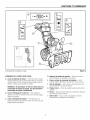
1
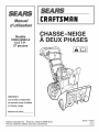
Owner's
Manual
IVlodel
C950-52943-0
13.5 T.P. 27 inch
AL STAGE
S OW T ROW
CAUTION:
You must
understand
manual
read and
this owner's
before
operating
unit.
Serial No.
Sears Canada inc., Toronto, Ontario M5B 2C3
Visit our Craftsman
website: www.sears.ca/craftsman
1738165
RevisionA
Rev.Date07/2009
Thankyou for purchasing this quality-built Craftsman snow thrower. We're pleasedthat you've placedyour confidence in the Craftsman
brand. When operated and maintained according to the instructionsin this manual, your Craftsman product will provide many years of
dependable service.
This manual contains safety information to make you aware of the hazards and risks associated with snow throwers and how to avoid
them. This snow thrower is designed and intendedonly for snow throwing and is not intendedfor any other purpose, it is important that
you read and understand these instructions throroughiy before attempting to start or operatethis equipment. This snow thrower
requires final assembly before use. Refer to the Assembly section for instructions on final assembly procedures. Follow the instructions completely. Save these instructionsfor future reference.
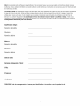
Snow Thrower:
Model Number
Revision
Serial Number
Engine:
Model Number
Revision
Serial Number
Date Purchased:
Store Where Purchased:
City:
Province:
Telephone:
NOTICE:Record this informationabout your snowthrower so that you wiii be able to provideit in case of loss or theft.
TABLEOFCONTENTS
OPERATORSAFETY....................................................................................
4
ASSEMBLY..............................................................................................
10
TOOLSREQUIRED
FORASSEMBLY
..........................................................................................................
10
CONTENTS
OFSHiPPiNGCARTON
..........................................................................................................
10
PARTSBAGCONTENTS
............................................................................................................................
10
UNPACKING
..............................................................................................................................................
11
UPPERHANDLE
ANDCRANKASSEMBLY
................................................................................................
12
CHECKTHECABLES
................................................................................................................................
12
SETTHELENGTH
OFTHECABLES..........................................................................................................
12
SPEED
SELECTLEVER
ASSEMBLY
..........................................................................................................
13
SNOWCHUTEASSEMBLY
........................................................................................................................
14
HEADLIGHT
ASSEMBLY
...........................................................................................................................
14
FEATURESAND CONTROLS..........................................................................
15
OPERATION.............................................................................................
17
BEFOREOPERATINGSNOWTHROWER................................................................................. 17
OPERATE
THESNOWTHROWER
..............................................................................................................
17
STOPTHESNOWTHROWER
....................................................................................................................
18
TRACTION
LOCKPINS.............................................................................................................................
18
CHECKTHEOIL(BEFORE
STARTING
ENGINE)
........................................................................................
18
FILLTHEFUELTANK................................................................................................................................
19
START
THEENGINE
..................................................................................................................................
19
STOPTHEENGINE
....................................................................................................................................
20
CLEARA CLOGGED
DISCHARGE
CHUTE
.................................................................................................
21
OPERATING
TIPS......................................................................................................................................
21
MAINTENANCE.........................................................................................
22
SERVICE
RECOMMENDATIONS
...............................................................................................................
22
LUBRICATE
AUGERGEARBOX.................................................................................................................
23
LUBRICATE
AUGERSHAFTFITTINGS
......................................................................................................
23
LUBRICATE
CHUTEROTATION
GEAR
.......................................................................................................
23
ENGINE
MAINTENANCE
...........................................................................................................................
24
CHANGE
THESPARKPLUG......................................................................................................................
25
ADJUSTSKIDHEIGHT
..............................................................................................................................
26
BELTADJUSTMENT
..................................................................................................................................
27
BELTGUIDEADJUSTMENT
......................................................................................................................
28
CHECKANDADJUSTTHECABLES
..........................................................................................................
28
AUGERSHEARPINREPLACEMENT
.........................................................................................................
30
CHECKTHETIRES.................................................................................................................. 30
STORAGE................................................................................................
31
OFFSEASON
STORAGE
............................................................................................................................
31
LUBRICATE
HEXSHAFTANDCHAINS.....................................................................................................
31
REMOVE
FROMSTORAGE
........................................................................................................................
31
TROUBLESHOOTING
...................................................................................
32
WARRANTIES...........................................................................................
34
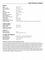
SPECIFICATIONS
.......................................................................................
37
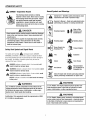
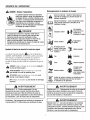
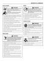
OPERATORSAFETY
DAHGER- Amputation Hazard
Hazard Symbols and Meanings
The dischargechute containsa rotating
impeller to throwsnow. Never clear or unclog
the dischargechutewith your hands. Fingers
can quickly become caughtand traumatic
amputation or severe lacerationwill result.
Always usea clean-outtool to dear or unclog
the dischargechute.
DANGER
• Hand contactwith the rotating impeller inside the discharge
chute is the most commoncause of injury associated with
snowthrowers.
• Thissnowthroweris capable of amputating handsand feet,
and throwingobjects. Read and observeall the safety
instructionsin this manual. Failure to do so will result in
death or serious injury.
Safety Alert - identifies safety informationabout
hazardsthat can result in personal injury.
Operator's Manual- Read and understand before
performingany activity or running snowthrower.
t_
A
The safety alert symbol _
and signal word (DANGER,
WARNING,CAUTION,or NOTICE)is used to indicate the likelihood and potential severity of personal injuryand/or damage to
the product. In addition, a hazardsymbol may be used to
represent the type of hazard.
_
ANGERindicates a hazard which, if not avoided, will
result in death or serious injury.
,_lll
WARNINGindicates a hazardwhich, if not avoided, could
result in death or serious injury.
_
AUTION indicates a hazardwhich, if not avoided, could
result in minor or moderate injury.
Keep a Safe
Distance from
Snowthrower
f _ %1[,,.,._i
_
_(_
SafetyAlert Symboland SignalWords
•
Rotating Impeller
Rotating Auger
L)
Never Reach into
Rotating Parts
_
/_-_
Rotating Gears
Thrown Objects
Fire
Explosion
Shock
ToxicFumes
Hot Surface
Recommended
Ear Protection for
ExtendedUse
Shut off engine and remove spark plug connector
beforeperformingmaintenance or repair work.
NOTICEindicates a situation that could result in damage
to the product.
WARNING
U.S.A. Models: Certain componentsin this productand its
related accessories containchemicalsknown to the state of
of California to causecancer,birth defects, or other reproductive harm. Wash hands after handling.
WARNING
U.S.A. Models: The engine exhaust from this productconrains chemicalsknown to the State of California to cause
cancer, birth defects, or other reproductiveharm.
WARNING
Certification: This equipmentmeets the requirementsof ANSI
B71.3-2005 for snowthrowers.
U.S.A. Models: Batteryposts,terminals, and related accessories containlead and lead components- chemicalsknown
to the State of California to causecancer and reproductive
harm. Wash hands after handling.
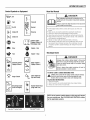
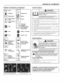
OPERATORSAFETY
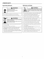
Readthe Manual
Control Symbols on Equipment
DANGER
._
J+J
Fuel
Forward
On Off
Neutral
Choke 0ff
R1--
Reverse
NI °"°"°°°
ElectricStart Engage(Down) &
Disengage (Up)
Stop
Slow
Engine - Run
Fast
Engine - Stop
[
Read,
understand,
andfollowall theinstructions
onthe
snowthrower
andintheoperator's
manual
before
operating
thisunit.
Failure
toobserve
thesafetyinstructions
in thismanual
will
resultin deathorseriousinjury.
,, Bethoroughlyfamiliarwith thecontrolsandthe properuse ofthe snow
thrower.
,, Makesureyou areproperlytrainedbeforeoperatingthe snowthrower.
,, Knowhowto stop the unit anddisengagethecontrolsquickly.
,, Neverallowanyoneto operatethe snowthrowerwithoutproperinstruction.
,, Alwaysfollow the instructionsin the operator'smanual,if thesnowthrower
will bestoredfor anextendedperiod.
,, Maintainor replacesafetyandinstructionlabelsasnecessary.
,, Neverattemptto makemajorrepairson thesnowthrowerunlessyou have
beenproperlytrained.Improperservicingof the snowthrowercan result
in hazardousoperation,equipmentdamage,andvoidingof the product
warranty.
Discharge Chute
DANGER
Discharge
chutecontainsrotatingimpellerto throwsnow.
Never
clearorunclogthedischarge
chutewithyourhands.
Fingerscanquicklybecome
caughtin theimpeller.
Always
usea clean-out
tool.
w
O
TractionControl Engage(Down)
='_'m
Auger Control Engage(Down)
Failureto observethesesafetyinstructions
will resultin
traumatic
amputation
orseverelaceration.
-dr
TOSAFELY
CLEAR
ACLOGGED
DISCHARGE
CHUTE
Auger Clutch
[_
(Left and Right)
ischarge Chute
,_
¢_
Chute
Deflector
(Up
and
Down)
DANGER:
Handcontact
withtherotating
impeller
inside
thedischarge
chuteis themost
common
causeof injury
associated
withsnow
throwers.
Neveruseyourhandstocleanoutthedischarge
chute.
FOLLOW
THESEIHSTRUCTIOHS:
1 ShutOFFtheengine
2 Wait10seconds
tobesuretheimpeller
bladeshavestoppedrotating
3.Alwaysusea clean-out
tool,notyourhands.
(High and Low)
Heated HandGrips
NOTE:Not all controlsymbols shownon this pagewill appear
on your snowthrower.See FEATURESANDCONTROLSsection
for the applicable symbols.
Easy-Turn
TM Traction
Control
TM Control
Free-Hand
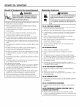
OPERATORSAFETY
Operationand EquipmentSafety
G
Fuel Handling
DANGER
DANGER
Thissnowthrower
is only assafeas theoperator.If it is
misused,or notproperlymaintained,
it canbe dangerous.
i Remember
youareresponsible
for yoursafetyandthat of
thosearoundyou.
* Keeptheareaof operationclearof all persons,particularlysmallchildren
andpets.
. Thoroughlyinspectthe areawherethe snowthrowerwill beusedand remove
all doormats,sleds,boards,wires,andotherforeignobjects.
. Do not operatethesnowthrowerwithoutwearingadequatewinterclothing.
. Wearfootwearthatwill improvefooting on slipperysurfaces.
. Usecautionto avoid slipping or falling especiallywhenoperatingthe
snowthrowerin reverse.
*, Neveroperatethe snowthrowerwithoutgoodvisibility or light. Alwaysbe
sureof yourfooting,andkeepafirm hold on the handles.
. Do notclearsnowacrossthe faceof slopes.Useextremecautionwhen
changingdirectionon slopes.Donot attemptto clearsteepslopes.
. Do not overloadthe machinecapacitybyattemptingto clearsnowtoo
quickly.
. Neveroperatethe snowthrowerat high transportspeedson slippery
surfaces.Lookbehindthe snowthrowerandusecarewhenoperatingin
reverse.
* Do not usethesnowthroweron surfacesabovegroundlevelsuchas roofsof
residences,garages,porches,or othersuch structuresor buildings.
. Operatorsshouldevaluatetheirabilityto operatethe snowthrowersafely
enoughto protectthemselvesandothersfrom injury.
. Thesnowthroweris intendedto removesnowonly.Do not usethesnow
throwerforany otherpurpose.
. Do notcarrypassengers.
*, Afterstrikinga foreignobject,shut OFFthe engine,disconnectthe cordon
electricmotors,thoroughlyinspectthesnowthrowerforany damage,and
repairthe damagebeforerestartingandoperatingthe snowthrower.
*, If the snowthrowervibratesabnormally,shut OFFthe engine.Vibrationis
generallyawarningof trouble.Seeanauthorizeddealerif necessaryfor
repairs.
. For modelsequippedwithelectricstartingmotors,disconnectthe power
cordafterthe enginestarts.
Fuelandits vaporsareextremelyflammableandexplosive,
Alwayshandlefuel withextremecare.
Failureto observethesesafetyinstructionscancausea fire
Ior explosionwhichwill resultin severeburnsor death.
WHENADDINGFUEL
* Turnoff engineandletcool at least2 minutesbeforeremovingthe fuel
cap andaddingfuel.
o Fill fueltank outdoorsor ina well ventilatedarea.
o Donot overfillthe fuel tank.Toallowfor the expansionof gasoline,do notfill
abovethe bottomof the fuel tankneck.
o Keepfuel awayfromsparks,openflames,pilot lights, heat,andother
ignitionsources.
o Checkfuel lines,cap,andfittings frequentlyfor cracksor leaks.Replaceif
necessary.
o Useanapprovedfuelcontainer.
o If fuelspills, wait until it evaporatesbeforestartingengine.
WHENSTARTINGENGINE
*, Ensurethatsparkplug, muffler,fuelcap, andair cleaner(if equipped)are in
placeandsecured.
. Donot crankthe enginewiththe sparkplug removed.
. If fuel is spilled,do not attemptto starttheengine,but movethe snow
throwerawayfrom theareaof thespill, andavoidcreatinganysourceof
ignition,until the fuelvaporshavedissipated.
*, Donot over-primethe engine.Followthe enginestartinginstructionsin this
manual.
. If theenginefloods,setchoke(if equipped)to OPEN/RUN
position,move
throttle(if equipped)to FASTpositionandcrankuntil enginestarts.
WHENOPERATING
EQUIPMENT
* Donot tip the snowthrowerat ananglewhichcausesthe fuelto spill.
. Donot chokethecarburetorto stopthe engine.
. Neverrunthe enginewiththe air cleanerassembly(if equipped)or the air
filter (if equipped)removed.
WHENCHANGINGOIL
* If you drainthe oil from the top oil fill tube,the fuel tankmustbeemptyor
fuel can leakout andresultin afire or explosion.
I WHENTRANSPORTING
EQUIPMENT
* Transport
withfueltankEMPTY,
orwithfuelshut-offvalveOFE
WHENSTORINGGASOLINEOREQUIPMENTWITHFUELIN TANK
*, Storeawayfromfurnaces,stoves,waterheaters,or otherappliancesthathave
pilot light or otherignitionsourcebecausetheycan ignitefuel vapors.
OPERATORSAFETY
Children
Moving Parts
DANGER
Keephands,feet,andclothingawayfromrotatingparts.
Rotating
partscancontactor entangle
hands,
feet,hair,
clothing,or accessories.
Failure
toobserve
thesesafetyinstructions
will resultin
traumatic
amputation
orseverelaceration.
* Whenever
cleaning,repairing,or inspecting
thesnowthrower,
makesurethe
engineis OFF,sparkplugwireis disconnected,
andall movingpartshave
stopped.
. Donot puthandsor feetnearor underrotatingparts.Keepclearof the
dischargeopeningat all times.
. Neveroperatethe snowthrowerwithoutproperguards,andothersafety
devicesin placeandworking.
. Neverleavethe snowthrowerunattended
whileengineis running.Always
disengagetheaugerandtractioncontrols,stop engine,andremovekeys.
. Keepall looseclothingawayfrom the front of thesnowthrowerandauger.
Scarves,mittens,danglingdrawstrings,looseclothes,andpantscanquickly
becomecaughtin therotatingdeviceandamputationwill occur.Tie up
long hairandremovejewelry.
. Runthe machineafewminutesafterdischargingsnowto preventfreeze-up
of thecollector/impeller.
. Disengagepowerto the collector/impellerwhensnowthroweris transported
or not in use.
DANGER
Tragicaccidents
canoccurif theoperator
is notalertto the
presence
ofchildren,Children
areoftenattracted
totheunit
andtheoperating
activity.Neverassume
thatchildrenwill
remain
whereyoulastsawthem.
o Keepchildrenout of theareaduringoperation.Childrenareoftenattractedto
the equipment.Bemindfulof all personspresent.
,, Bealertandturn unit off if childrenenterthe area.
,, Neverallowchildrento operatethe unit.
,, Useextracarewhenapproachingblindcorners,shrubs,trees,or other
objectsthatmayobscurevision.Childrenmaybe present.
Engine Safety
DANGER
__
I_
and
instructionsin
maintenance
this
othe
f the
manualwill
engine.Failureto
result in observe
deathpropercare
or
theserious
safety
Safeoperationof
snowthrowerrequiresthe
injury.
,, Disengageall clutchesandshift into neutralbeforestartingthe engine.
,, Letthe engineadjustto outdoortemperatures
beforestartingto clearsnow.
,, Usea groundedthree-wireplug-infor all snowthrowers
equippedwith
electricdrivemotorsor electricstartingmotors.
Thrown Objects
DANGER
Objects
canbepickedupbyaugerandthrownfromchute.
Neverdischarge
snowtowardbystanders
or allowanyonein
frontofthesnowthrower.
Failure
to observe
thesesafety
instructions
willresultin deathor seriousinjury.
* Alwayswearsafetyglassesor eyeshieldswhileduringoperation,andwhile
performingan adjustmentor repair.
,, Alwaysbeawareof the directionthe snowis beingthrown.Nearby
pedestrians,pets,or propertymaybe harmedby objectsbeingthrown.
,, Beawareof yourenvironmentwhileoperatingthesnowthrower.Running
overitemssuch as,gravel,doormats,newspapers,
toys,androckshidden
undersnow,canall bethrownfrom the chuteor jam inthe auger.
,, Useextremecautionwhenoperatingon or crossinggraveldrives,walks,or
roads.
,, Adjustthecollectorhousingheightto cleargravelor crushedrocksurface.
,, Neveroperatethe snowthrowernearglassenclosures,automobiles,window
wells, drop-otis,andthe likewithoutproperadjustmentof the discharge
chuteangle.
,, Familiarizeyourselfwiththe areain whichyou planto operatethesnow
thrower.Markoff boundariesof walkwaysanddriveways.
DANGER
Enginesgiveoff carbonmonoxide,an odorless,colorless,
poisongas.
Breathingcarbonmonoxidecancausenausea,fainting,
or death.
o Startandrun engineoutdoors.
o Donot runthe enginein anenclosedarea,evenif doorsor windowsare
open.
OPERATORSAFETY
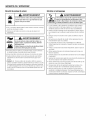
Maintenanceand Storage
Engine Safety (Continued)
WARNING
j Startingenginecreatessparking.
i
,
j Sparkingcanignitenearbyflammablegases.
Explosionandfire could result.
* Ifthereis naturalor LPgas leakagein area,do not startengine.
* Donot usepressurizedstartingfluids becausevaporsareflammable.
This snowthrowermustbeproperlymaintainedto ensuresafe
operationand performance.
Failure to observethe safety
WARNING
instructionsin this manualcould resultin deathor serious
injury.
o Whenperformingany maintenanceor repairson the snowthrower,
shut OFF
theengine,disconnectsparkplug wire,andkeepthewire awayfrom the
plug to preventsomeonefrom accidentlystartingthe engine.
* Checkshearboltsandotherhardwareatfrequentintervalsfor proper
tightnessto besurethe snowthroweris in safeworkingcondition.
* Keepnutsandboltstight andkeepsnowthrowerin goodcondition.
* Nevertamperwith safetydevices.Checktheir properoperationregularlyand
makenecessaryrepairsif theyarenot functioningproperly.
,_I_IISIIII_$11,, Runningthe engineproducesheat.Engineparts, especially
"="='===_
i muffler,becomeextremelyhot,
Failureto observethesesafetyinstructionscould result in
i severethermalburnson contact.
* Componentsaresubjectto wear,damage,anddeterioration.Frequently
checkcomponentsandreplacewith recommended
parts,when necessary.
* Checkcontrol operationfrequently.Adjustandserviceas required.
* Useonly factoryauthorizedreplacement
partswhenmakingrepairs.
* Alwayscomplywithfactoryspecificationson all settingsandadjustments.
* Nevertoucha hot engineor muffler.Allow muffler,enginecylinder,andfins
to coolbeforetouching.
* Removedebrisfrom mufflerareaandcylinderarea.
* Installandmaintaininworkingorderasparkarresterbeforeusingequipment
on forest-covered,
grass-covered,or brush-coveredunimprovedland.
* U.S.A.Models:It is a violationof CaliforniaPublicResourceCode
Section4442to useor operatetheengineon or nearanyforest-covered,
brush-covered,
or grass-coveredlandunlessthe exhaustsystemis equipped
with asparkarrestermeetingany applicablelocalor statelaws.Otherstates
or federalareasmayhavesimilar laws.
* Onlyauthorizedservicelocationsshouldbe utilizedfor majorserviceand
repairrequirements.
* Useonly attachments
andaccessoriesapprovedby thefactory(suchas
wheelweights,counterweights,
or cabs).
* Neverattemptto makeanyadjustmentswhilethe engineis running(except
whenspecificallyrecommended
bythe factory).
,, Donot allowgreaseor oil to contactthe rubberfrictionwheelor the disc
driveplate.If the discdriveplateor frictionwheelcomein contactwith
greaseor oil, damageto the rubberfrictionwheelwill result.
OPERATORSAFETY
Lookfor this symbol to indicate importantsafety
precautions.This symbolindicates: "Attention! Become
Alert! Your Safety is At Risk."
_
I
cannotbe
read,orderreplacement
decalswornor
from yourlocaldealer.
ARNING:If
anysafetydecalsbecome
damagedand J
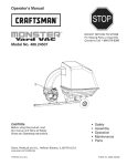
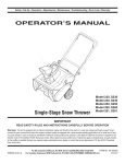
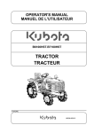
Before operatingyour snow thrower, read the safety decals
as shown on yoursnow thrower. The cautionsand warnings
are for yoursafety. To avoid a personalinjuryor damageto
yoursnow thrower, understandand fo ow al the safety decals.
Part No. 1737872
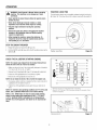
Shift Decal
I
I
Part He. 1737870
TractionControl Decal
Part He. 1737868
Auger ControlDecal
\
EngineDecals
Amputation
hazard
Contactwith moving parts inside
chute will Causeserious injury,
= Shut off engine before unclogging
dischargechute.
. Use clean-out tool, not hands!
Risque d ,amputation
de la goulotte provoqueradegraveshlessures.
ArrOterle mote,r avant de d_gager la go,lotto
d'_jection.
= Utiliser I'outil ded_gagement,pas los mains!
Part Ho. 278297
Part Ho. 1737865
ChuteDanger Decal
,.-._. _..::....
FAUlLYXXXXX.XXXXXX
XXXXXX
Part Ho. 277953
ProductID Humber&
Serial Humber Decal
(Rear of Motor Box)
- Contact with a_er will
cause seri{}us injury.
• _eep hands, leet and
_lothing away.
°To_tco_lactavecla
• Keep hys_aneers away.
et vgtemenls _ _is_ance.
• Tenir vos pieds, vos mai_s
° Ten[_ les spect_teurs
dislance.
Thrown
Hazard
tafl_re provoqeera de
Part Ho. 1737866
graveshlessures.
Auger Danger Decal
Objects
_i ;_
=Heverdirectffischarge
_h_tetowardspers_ns
_rproperly.
Readlhe_perator's
man_ailor_perating
_at_lyiflstroct_ns.
.He i_rnals dlri_erla
Oangerobjetsp_ojet_s
chute en dire_tio_ des
"_
and
Shutoff engine aed
remove key before
pertorming maintenance
or rep_irwork.
Safety Decals
Risque d'amputation
Amputation Hazard
pe_sonnes
matdtiels.
ou biefl_
s_,_ril_ et d'_tilisation duns
Lireiles¢o_si_esde
le manuel _rutiJi_tio0.
_-_ _,_
Arrgter le moteur eI
retirerla
cld avant
d'elfect_tt_ol_Iretien
outo_tet_p_ration.
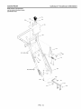
,,,_
Figure I
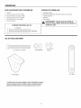
ASSEMBLY
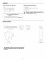
TOOLSREQUIREDFORASSEMBLY
CONTENTSOF SHiPPiNGCARTON
122211-
11111-
Knife
1/2" wrenches(or adjustablewrenches)
9/16"wrenches(or adjustablewrenches)
3/4" wrenches(or adjustablewrenches)
3/8" wrenches(or adjustablewrenches)
Pairpliersor screwdriver
SnowThrower
Containerof FuelStabilizer(Locatedin PartsBag)
SnowChuteAssembly
CrankAssembly
PartsBag
WARNING:Alwayswear safety glasses or eye shields
whiJe assembling snow thrower.
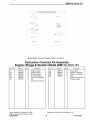
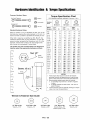
HOW TO MEASURE SCREW SIZE
LENGTH
DIAMETER
PARTSBAGCONTENTS
* 2=1/4=20 x 1.75
* 2=1/4=20
Hex nut
* 2=Spacer
*2 =Wrenches
1 = Shifter Knob
(not actual size)
*NonAssemblypartsand powercordcanbefoundin the PartsBagshipped
with thesnowthrower.Thepartscanbestoredin thetool boxlocatedon top
of thebeltcover.
10
I
ASSEMBLY
NOTE:Reference
to rightand lefthandsideof thesnowthroweris fromthe
operator'spositionatthe handle.
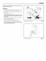
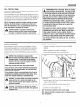
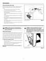
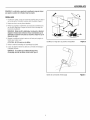
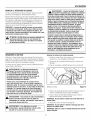
UNPACKING
1. Usingknife,cut alongthedottedlinesaroundthetop andbottomof
carton.Thenremovecartonmaterialasshownin Figure2.
2. Removeshearpinsandcotterpinsfrompartsbagand placein shear
boltstoragebox.
3. Locateand removethepartsbag.
NOTE:Setthefuelstabilizerasideuntiladdinggasolineto thefuel
tank.Werecommend
thatfuelstabilizerbeaddedto thefueleachtime
thetankis filled.
4. Rollthesnowthroweroff thecartonby pullingon thelowerhandle.
CAUTION:
DONOTbackovercables.
5. Remove
thepackingmaterialfrom thehandleassembly.
6. Cuttiessecuringtheclutchcontrolcablesto the lowerhandle.
Unpackingthe Snowthrower
Figure 2
Clutch Control Cables
Figure3
NOTE:If thecableshavebecomedisconnectedfromtheclutchlevers,
reinstallthecablesasshownin Figure3.
11
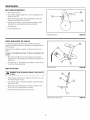
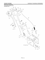
ASSEMBLY
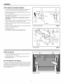
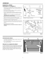
UPPERHANDLEAND CRANKASSEMBLY
1. Loosen,butdo not removethescrews,flatwashers,Iockwashers,
and
hexnutsin theupperholesof thelowerhandle(seeFigure4).
Adaptor Boot
2. Remove
thefastenersandthecrankassemblyeyeboltfromthelower
holesofthe lowerhandle.
_olt
!
3. Raiseupperhandleintooperatingposition.Upperhandleshouldbeto
theoutsideof thelowerhandle.
NOTE:Makesurethecablesarenotcaughtbetweentheupperand
lowerhandle.
4. Installthefastenersandthecrankassemblyeyeboltthatwereremoved
in step2. DONOTtightenuntil all fastenersare in place.
Eye Bolt
5. Attachthecrankrod (A, Figure5) to theuniversaljointassembly(B)
with thehair pin (C).
Flatwasher
Flatwasher
6. Tightennuton eyebolt. Makesureeyebolt is properlyalignedandthe
crankcanfreelyrotate(seeFigure4).
Upper HandleAssembly
Figure4
Crank Assembly
Figure5
Checkthe Cables
Figure6
7. Tightenall handlebolts.
NOTE:Makesurecrankdoesnottouchcarburetorcover.
CHECK THE CABLES
1. If controlcableshavebecomeunattached
from motormountframe,reconnectcablesasshownin Figure6.
2. Forcableadjustments,
see"CheckandAdjusttheCables"in the
MAINTENANCE
section.
SET THE LENGTH OF THE CABLES
Thetractiondriveandaugerdrivecables(AandB, Figure6) wereadjusted
atthefactoryandno adjustments
shouldbenecessary.
However,
afterthe
handlesareput in theoperatingposition,thecablescanbetootight or too
loose,if anadjustmentis necessary,
see"CheckandAdjusttheCables"in
theMAINTENANCE
section.
12
ASSEMBLY
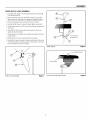
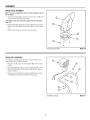
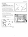
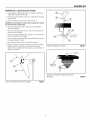
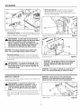
SPEED SELECT LEVER ASSEMBLY
1. Cutplastictie(A,Figure7) securingspeedselectleverassembly(B)
to theshifterbracket(C).
2. RemoveIocknut(A, Figure8),washer(B),spring(C),andbolt (D).
NOTE:
Viewis fromright sideof unit standingin operator'sposition.
3. Positionspeedselectorleverassemblyas shownin Figure9.
4. Reinstallbolt(D, Figure8), spring(C),washer(B)and Iocknut(A).
5. TightenIocknutuntil1/8 to 3/16 inchof theboltthreadsprotrudepast
the Iocknut.
6. Threadthe3/8-16" hexjamnut(E) ontothelever(F) untilthenut
reachestheendof thethread.
7. Threadthe plasticknob(G)asfaras possibleandensurethattheknob
pointsforward.
1/8to3/8inchof
exposted
thread
8. Tightenthe3/8-16" hexjamnutagainsttheknobsecurely.
9. Moveshifterthroughall speedsto ensurepropertensionofthespring.
If shifterleversticksin anyof thenotches,loosenIocknut1/2 turnata
time untilshifterlevermovesmorefreely.
Shifter Handle
Figure 8
Shifter Bracket
Control Panel
Shift Lever and Bracket
Figure7
Control Panel and Shifter Bracket
13
Figure 9
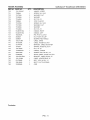
ASSEMBLY
SNOW CHUTEASSEMBLY
NOTE:Thechuteringassembly(A,Figure10)comesinstalledon theunit
fromthefactory.
1. Turncrankassembly(Figure4) untilthearrowon outerring (B, Figure
10)of chuteringassemblypointsforward.
NOTE:Makesuretheslot in thechutering alignswith thearrowonthe
outerring.
2. Installchutedeflector(C) usingfourscrews(D)and nuts(E)in holes
asshown.Thechutedeflectormustpointforwardfor properinstallation.
3. Tightenscrewssnuglybutbecarefulnotto over-tighten.
Snow Chute Assembly
Figure 18
Headlight Assembly
Figure 11
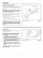
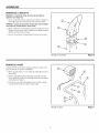
HEADLIGHT ASSEMBLY
Theheadlightismountedon therightsideofthe upperhandle,itisinstalledupside-downfor shippingpurposes,
1. Remove
the nut(A,Figure11) and Iockwasher
(B)from thecarriage
bolt(C).
2. Turntheheadlight(D)to thetop sideof theupperhandle(E).Ensure
externaltooth Iockwasher
(F)andsaddlewasher(G)arein placeas
shownin Figure11.
3. InstallthenutandIockwasher
to securetheheadlightto thehandle.
Theheadlightshouldpointtowardthesnowclearingpath.
14
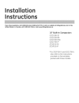
FEATURES
AND CONTROL
S
®
1 _-- I;__-->-
R1
I
©
®
a
_
®
i
,_-,llllt
o___
®
-tS-
®
Y
\
"iJ
Snow Thrower Controls
figure 12
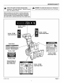
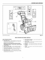
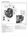
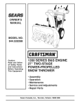
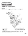
SNOWTHROWERAND ENGINECONTROLS
SNOWTHROWERCONTROLS
E. ChuteDeflectorWing Nut -- Usedto controltheangleof the
chutedeflector(up or down).
A. Speed Select Lever- Allowstheoperatorto useoneof six (6)
forwardandtwo(2)reversespeeds(seeFigure12).Toshift, move
speedselectleverto desiredposition.
f. Clean-Out Tool-- Usedto removesnowanddebrisfromthedischargechuteandtheaugerhousing.
NOTICE:Do not move speed select lever while Traction
Drive Clutch is engaged. This may result in severe damage
to drive system.
G. Skid Shoe -- Usedto adjustgroundclearanceofaugerhousing.
H. Headlight-- Usedto operatethesnowthrowerin poorlighting
conditions.
B. Auger Drive Clutch Lever-- Usedto engageanddisengagethe
augerandimpeller.Toengagepushdown,to disengagerelease.
I. Toolbox -- Spareshearpins,shearboltwrenchesandspacersare
locatedin toolbox.
C. Traction Drive Clutch Lever-- Usedto propelsnowthrowerforwardor reverse.Pushdownto engage,releaseto disengage.
D. Chute Rotation Crank -- Usedto changedirectionof thesnow
discharge.Turnhandleclockwiseto turnchuteto right.Turnhandle
counterclockwise
to turn chuteto left.
15
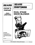
FEATURES
AND CONTROLS
®
I÷1I×l
®
/
®
®
®
EngineControls
Figure 13
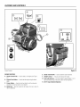
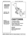
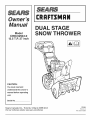
ENGINECONTROLS
E. Starter Cord Handle -- Usedto starttheenginemanually.
A. Choke Control Knob-- Usedto starta cold engine(seeFigure
13).
Fo ON/OFFSwitch -- Usedto startand stoptheengine.
G. Fuel Tank and Cap-- Fill thefueltankto approximately
1-1/2 in.
(38 mm)belowthetopof theneckto allowfor fuelexpansion.
B. Electric Start Button -- Usedtostarttheengineusingtheelectric
starter.
H. 0il Fill Cap (Extended Dipstick)
C. Primer Button -- Usedto injectfueldirectlyintothecarburetor
manifoldto ensurefaststartsin coolweather.
D. Safety Key-- Mustbe insertedto startengine.Pull out to stop.Do
notturn safetykey.
16
OPERATION
BEFOREOPERATING SNOW THROWER
NOTE: This snow thrower was shipped WiTH OiL in the
engine. See "Before Starting Engine" instructions in the
OPERATIONsection of this manual before starting engine.
Checkthe fasteners.Makesureall fastenersare tight.
Readthis OPERATOR'S
MANUALand OPERATOR
SAFETYbefore
operatingyoursnow thrower. Comparethe illustrationswithyour
SNOWTHROWERtofamiliarize yourselfwith the locationofvariouscontrolsand adjustments. Savethis manual for future referonce.
WARNING:The
operation
of any
thrower
can
in foreign
objects being thrown
into the
eyes, which
result in
severe eye damage.
Always
wearsnow
safety
glasses
orresult
eye shields
beforebeginningsnow
thrower
operation.
We can
recommend
standard safety glasses or Wide Vision Safety Mask over spectacles.
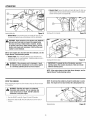
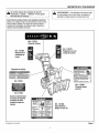
OPERATETHESNOWTHROWER
5. Engagetheaugerdriveclutchlever(A,Figure15).
Themosteffectiveuseof thesnowthrowerwill beestablishedbyexperience,takinginto consideration
theterrain,windconditions,andbuilding
locationwhichwill determinethedirectionof thedischargechute.
DOWN
UP
EngagePosition
DisengagePosition
6. Engagethetractiondriveclutchlever(B).Asthesnowthrowerstarts
to move,maintaina firm hold onthehandlesandguidethesnow
throweralongthecuttingpath.Donotattemptto pushthesnow
thrower.
NOTICE:Do not throwsnowtoward a buildingas hiddenobjects
could be thrownwith sufficient force to causedamage.
1. Starttheengine.See"ToStartEngine"inthis section.
7. Tostopforwardmotion,release
thetractiondriveclutchlever(B).
2. Rotatethecrank(A, Figure12) to setthedirection(left or right)of the
dischargechute.
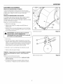
3. Adjustthesnowchutedeflector.Loosenthewingnut (A,Figure14)on
thesideof thesnowchuteandraisethechutedeflectorfor more
distance,or lowerit for lessdistance.Thentightenthewing nut.
,)',
",,j
CiL2
\\
//
Control Levers
Figure15
8. Tostoptheauger,release
theaugerdriveclutchlever(A).
Adjust Chute Deflector
_
9. Tomovethesnowthrowerbackwards,
movethespeedselectlever(A,Figure12)intofirstor secondreverse
(R1or R2),andengage
thetractiondrive
clutchlever(B,Figure15).
Figure 14
AUTION:Before operating, make sure the area in front
of the snow thrower is clear of bystandersor obstacles.
_
NOTE:Always release the tractioncontrol lever beforemoving
the speed select lever.
,, Keep hands, feet, hair, and loose clothing away from
any moving parts on engine and snow thrower.
4. Usethespeedselectlever(A, Figure12) to selecttheforwarddrive
speed.Setthespeedselectleverto oneof thefollowingpositionsas
determinedby snowconditions:
1-2
3
4-5
6
WARNING:
Never
run engine
in an enclosed,
poor ventilated
area.
Engine indoorsor
exhaust containsCARBON
MONOXIDE,an ODORLESSand DEADLYGAS.
,, Temperatureof muffler and nearby areas can exceed
150°F (66°C). Avoid these areas.
,, DONOT allow children or youngteenagers to operate or
be near snow thrower while it is operating.
Wet,Heavy,Slushy,ExtraDeep
Moderate
VeryLight
Transport
NOTE:When clearing wet, heavy, snow, it is recommended that
the ground speed of the unit be reduced, maintain full throttle,
and do not attempt to clear the full width of the unit.
17
OPERATION
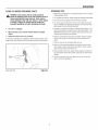
TRACTIONLOCKPiNS
,_
WARNING:
Read
Operator's
before operating
machine. This
machine
can Manual
be dangerousif
used
carelessly.
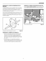
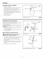
Therighttractionwheelcanbecompletelyreleasedusingthe lockingpin
(A,Figure16).This allowstheunit to beeasilymovedwiththeengineoff.
,, Never operatethe snowthrower without all guards,covers,
shields in place.
,, Never direct dischargetowards windows or allow
bystandersnear machine while engine is running.
,, Stop the engine whenever leaving the operating
position.
,, Disconnectspark plug beforeuncloggingthe impeller
housingor the dischargechute and before making
repairs or adjustments.
,, Whenleavingthe machine, removethe safety key. To
reducethe risk of fire, keep the machine cleanand free
from spilled gas, oil, and debris.
STOPTHESNOWTHROWER
1. Release
thetractiondriveclutchlever(B,Figure15).
2. PushtheON/OFF
switch(A,Figure22)totheOFFpositionandpulloutthe
safetykey(B).
Traction Lock Pins
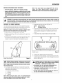
CHECKTHE OiL (BEFORE STARTING ENGINE)
Figure 16
oF
°C
NOTE:The engine was shippedfrom the factory filled with oil.
Check the level of the oil. Add oil as needed.
0_._
1. Makesuretheunit is level.Usea high qualitydetergentoil classified
"ForServiceSF,SH,SJ, SL,or higher".
50
2. Remove
theoilfill cap/dipstick
(A,Figure17)andwipewitha cleancloth.
3. Insertthe oilfill cap/dipstick
andturnclockwiseto tighten.
32
4. Removetheoil fillcap/dipstick
andchecktheoil.
14
NOTE:Do not checkthe level of the oil while the engine runs.
-4
5. If necessary,
addoil until theoil reachestheFULLmarkon theoil fill
cap/dipstick.Donotaddtoo muchoil.
_''__"
'
_'_ 40
'_"...............30
_
_
€
-22
6. Tightentheoil fillcap/dipstick
securelyeachtime youchecktheoil
level.
Below40°F(4°C)the use ofSAE30will result in hardstarting.
** Above80°F (27°C)the use of 10W-30maycauseincreasedoil consumption=
Check
oil levelmorefrequently.
NOTE:For extreme cold operating conditionsof O°F(-18°C) and
below, use a synthetic5W30 motor oil for easier starting.
NOTE:S.A.E. 5W30 motoroil may be used to make starting
easier in areas where the temperature is 20°F (-7°C) to O°F
(-18°C). Synthetic 5W30 is acceptable for all temperatures.
DO NOT mix oil with gasoline. See Chart for oil recommendations.
FULL
Checkingthe Oil
18
Figure 17
OPERATION
FiLL THE FUEL TANK
_
ARNING:Gasolineis
flammable. Always
use caution
when
handlingor storinggasoline.
Turnengineoff
and
let enginecoolat least two minutes beforeremovingthe gas
cap. Do not add gasoline tothe fuel tankwhile snowthrower
is running,hot, or when snow throweris in an enclosed area.
Keep away from open flame, electricalsparksand DONOT
SMOKEwhilefilling the fuel tank. Never fiil the fuel tank
completely;butfill thefuel tankto within1-1/2 inches(3.8
ram) from thetop to providespace for the expansionof the
fuel. Alwaysfill fuel tankoutdoors and usea funnel or spout
to preventspilling. Make sure to wipe up any spilled fuel
before starting the engine.
Thisengineis certifiedto operateon gasoline.ExhaustEmissionControl
System:EM(EngineModifications).
Fillthefueltankwithfresh,clean,unleaded
regular,
unleaded
premium,or reformulatedautomotivegasolinewith a minimumof 85 octanealongwith a
fuelstabilizer(follow instructionson fuelstabilizerpackage).DONOTuse
leadedgasoline.Werecommend
thatfuelstabilizerbeaddedto thefuel
eachtimethat gasolineis addedtothefueltank.
NOTE:Winter grade gasoline has higher volatility to improve
starting. Be certain containeris clean and free from rust or
other foreign particles. Never use gasoline that may be stale
from long periodsof storagein the container.
,_b
Store gasoline in a clean, approvedcontainer,and keep the
cap in placeon the container.Keepgasoline in a coolwell
ventilatedplace; neverin the house.Never buy more than a
30 day supply of gasoline to assure volatility.Gasolineis
intendedto be usedas a fuel for internalcombustionengines;
therefore,do notuse gasoline for any other purpose. Since
many childrenlike the smell of gasoline, keep it out of their
reach becausethe fumesare dangerousto inhale, as well as
being explosive.
CAUTION:DO NOT use gasoline containingany
amount of alcohol as it cancauseserious damage to
the engine or significantly reducethe performance.
START THE ENGINE
Start the engine as follows:
1. Checktheoil level.Seethe"Check/Add
Oil"sectionin theENGINE
MANUAL.
Besurethatengineoil isatFULLmarkontheoil fill cap/dipstick.
Thesnow
thrower
engineisequipped
withanA.C.electric
starter
andrecoilstarter.
Before
starting
theengine,
becertainthatyouhavereadthefollowinginformation.
2. Makesureequipment
drivecontrolsaredisengaged.
If enginefloods,setthechoketotheOPEN/RUN
positionandcrankuntiltheenginestarts.
,_
3. PushtheON/OFFswitch(A,Figure18)totheONposition.
WARNING:
Theelectric starteris
equipped
with
a
three-wirepowercordand
plugdesigned
to
operateon
AC
householdcurrent.Thepowercordmust be properly
groundedat all times toavoid thepossibility
of electric
shockwhich cancauseinjuryto theoperator.Followall
instructions
carefullyas set forth:
Makesureyourhousehasa three-wiregroundedsystem.
Ifyou are notsure,ask a licensedelectrician.If yourhousedoes
nothavea three-wire groundedsystem,do notusethis electric
starterunderanycondition.
If yourhousehas a three-wiregroundedsystembut a three-hole
receptacleis notavailabletoconnectthe electricstarter, havea
three-holereceptacleinstalledbya licensedelectrician.
,_h
StartingEngine
WARNING:To connectpower cord, always connectthe
power cordfirst to the switch box located on the
engine and then plug the other end into a three-hole
grounded receptacle.
Figure18
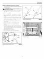
4. Insertthesafetykey(A, Figure19)into thesafetykeyslot and push
fully in to theRUNposition.
5. Turnthechokeknob(B)fully clockwiseif engineis cold.
NOTE:Do not use the choketo start a warm engine.
WARNING:To disconnectthe power cord, always
unplug the end connectedto the three-hole grounded
receptacle first.
6. Pushtheprimerbutton(C)two times.
NOTE:Do not usethe primer to start a warm engine.
NOTE:Ensurethat electric extension cordis removedfrom the
power receptacle.
19
OPERATION
9. Electric Start: Depress
thestarterpushbutton(A,Figure
21).Afteryou
starttheengine,
firstdisconnect
theextension
cordfromthewallreceptacle
andthenfromthepowercordreceptacle
(B).
Inserting
Safety
Key
Startingwith CordHandle
Figure 19
Figure 20
7. Rewind Start: Firmlyholdthestartercordhandle(A,Figure
20).Pull
thestartercordhandleslowlyuntilresistance
isfelt,thenpullrapidly.
,_
WARNING: Rapid retraction of the starter cord (kickback)
will pull your hand and arm toward the engine faster
than you can let go. Brokenbones, fractures, bruises,
or sprains could result. When starting engine, pull the
starter cordslowly until resistanceis felt and then pull
rapidlyto avoid kickback.
NOTE:if the engine does not start after three attempts, see the
Engine Manual Troubleshootingsection.
8. Electric Start: Firstconnecttheextension
cordtothepowercord
receptacle
andthenintoawallreceptacle.
If additional
extension
cordis
required,
makesureit is three-wire.
4_
Startingwith ElectricStart
Figure21
IMPORTANT:To extend the life of the starter, use short
starting cycles(five secondsmaximum). Wait one minute
between starting cycles.
WARNING: if the extension cord is damaged, it must
be replaced bythe manufacturer(or its service agent)
or a similarly qualified personto avoid a hazard.
NOTE:if the engine does not start after three attempts, see the
Engine Manual Troubleshootingsection.
NOTE:Do not lose the safety key. Keepthe safety key in a safe
place. The engine will not start without the safety/ignitionkey.
STOP THE ENGINE
Beforestoppingtheenginefor a fewminutesto helpdry off anymoisture
on theengine.
,_
WARNING:
and vaporsare
extremely
flammable Gasoline
and explosive.
Fire or explosion
can
cause severe burns or death. DO NOT chokethe
carburetorto stop the engine.
1. PushtheON/OFFswitch(A,Figure22) totheOFFposition.
2. Removethesafetykey(B).Keepthesafetykeyoutof the reachof
children.
Stopping
Engine
20
Figure 22
OPERATION
OPERATINGTIPS
CLEARA CLOGGEDDISCHARGECHUTE
,_
1. Mostefficientsnowthrowingis accomplished
whensnowis removed
immediatelyafterit falls.
WARNING:Handcontactwith
the most
rotating
impeller
inside the dischargechute is the
common
cause of
injury associated with snow throwers. Never clear or
unclog dischargechute with your hands, or while engine
is running. Fingers can quickly become caughtand
traumatic amputation or severe lacerationcan result.
2. Forcomplete
snowremoval,
slightlyoverlapeachswathpreviously
taken.
3. Snowshouldbedischargeddownwindwheneverpossible.
4. Fornormalusage,setthe skids1/8 inch(3 mm)belowthe scraper
bar.Forextremelyhard-packedsnowsurfaces,the skidsmaybeadjustedupwardto ensurecleaningefficiency.
5. Ongravelor crushedrocksurfaces,theskidsshouldbesetat 1-1/4
inch(32 mm)belowthescraperbar(see"AdjustSkidHeight"in the
MAINTENANCE
sectionof this manual).Rocksandgravelmustnot
bepickedupandthrownbythemachine.
o SHUTOFFTHEENGINE!
,, Wait10 secondsto besurethatthe impeller
bladeshavestopped
rotating.
,'
Alwaysusea clean-outtool, notyourhands.
6. Afterthesnowthrowingjob hasbeencompleted,allowtheengineto
idle for a fewminutes,to meltsnowand iceaccumulated
on the
engine.
A clean-outtool(A,Figure23) isattached
to eitherthehandleor thetopofthe
augerhousing.Usetheclean-outtooltoremovesnowfromtheaugerhousing.
7. Cleanthesnowthrowerthoroughlyaftereachuse.
//'
8. Removeiceandsnowaccumulation
andall debrisfromtheentire
snowthrower,andflush withwater(if possible)toremoveall saltor
otherchemicals.Wipesnowthrowerdry.
/
9. Beforestartingsnowthrower,alwaysinspectaugersand impellerfor
iceaccumulationand/ordebris,whichcouldresultin snowthrower
damage.
10. Checkoil levelbeforeeverystart.Makesurethe oil is attheFULL
markontheoil fill cap/dipstick.
\\'\
'i
Clean-OutTool
Figure23
21
MAINTENANCE
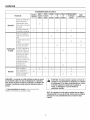
SERVICERECOMMENDATIONS
FIRST BEFORE AFTER
5
EACH
EACH
HOURS
USE
USE
PROCEDURE
Checkto MakeSure
AugerBladeStopsWithin
5 SecondsAfterRight
ControlLeveris Released
SAFETY
LubricateControlLevers
andLinkages
EVERY
5
HOURS
EVERY
10
HOURS
EVERY BEGINNING
BEFORE
25
EACH
STORAGE
HOURS
SEASON
v"
,/
,/
CheckSnowthrower
for
LooseHardware
,/
v"
,,,"
LubricateHexShaftand
Chains
v"
LubricateAugerShaft
Fittings
v"
v"
v"
SNOWTHROWER LubricateChuteRotation
GearandDeflector
Mechanism
v"
RemoveAll Snowand
Slushoff Snowthrower
to
v"
PreventFreezingof Auger
or Controls
CheckTirePressure
L_______
i
,/
i ,,,,,
i
Oil,Check
ENGINE
Oil,Change
,/
v"
,/
,/
v"
v"
Checkand Replace
SparkPlug
v"
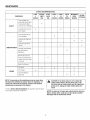
NOTE:The warrantyon this snowthrower does not cover items
that have been subjectedto operator abuse or negligence.To
receive full value from the warranty, operator mustmaintain
snowthroweras instructedin this manual.
A
TheaboveService Recommendations aresuppliedto assisttheoperator to properlymaintainthesnowthrower.
v"
CAUTION:Do not allow grease or oil to contactthe
rubberfriction wheel or the disc drive plate, if the
disc drive plate or friction wheel come in contactwith
grease or oil, damage to rubberfriction wheel will
result.
NOTICE:if grease or oil comesinto contactwith the disc drive
plate or friction wheel, make sure to clean plate and wheel
thoroughlywith an alcohol base solvent.
22
MAINTENANCE
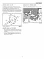
LUBRICATE
AUGERGEARBOX
LUBRICATE
CHUTEROTATIONGEAR
Theaugergearboxis lubricatedatthefactoryand shouldnotrequire
additionallubrication.If for somereasonthelubricantshouldleakout,
or if theaugergearboxhasbeenserviced,add LubriplateGR132Greaseor
equivalent.Maximum3-1/4 ounces,(92 grams)shouldbeused.
Lubricate
thechute rotation gear(A,Figure25)andshaft (B)withautomotivetypeoil everytwenty-five
(25)operating
hours.
Removefiller plug (A,Figure24),oncea year.If greaseis visible,do not
add.If greaseis notvisible,usea pieceoffinewire, likea dipstickto check
if thereis greasein thegearbox.MobiluxEP1and ShellAIvaniaEP1are
suitableequivalents.
ChuteRotationGear
LubricatingAugerGearBox
Figure 24
LUBRICATE
AUGERSHAFTFITTINGS
1. Usinga handgreasegun, lubricatetheaugershaftfittings (B,Figure
24) everyten (10)operatinghours.Eachtimea shearpin is replaced,
theaugershaft(C) MUSTbe greased.(See"AugerShearPinReplacement"section.)
2. Forstorageor whenreplacingshearpins, removeshearpinsand
lubricateaugershaftfittings (B).Rotateaugersseveraltimeson the
shaftandreinstalltheshearpins.
23
Figure 25
MAINTENANCE
ENGINE MAINTENANCE
Check Crankcase Oil Level - Beforestartingengineand aftereach8
hoursof continuoususe.Add therecommended
motoroil asrequired.
NOTE:Over filling the engine can affect performance.Tighten
the oil fill cap securely to prevent leakage.
Full
Change Oil - Every50 hoursof operationor atleastoncea year,evenif
thesnowthroweris not usedfor fifty hours.Usea clean,high quality
detergentoil. Fill thecrankcase
to FULLline on dipstick(A, Figure26). Be
sureoriginalcontaineris marked:A.P.I.service"SF"or higher.Do notuse
SAEIOW40oil (asit maynotprovideproperlubrication).See Chart for
oil recommendations.
Drain Oil - Positionsnowthrowersothattheoil drain plug(A, Figure
27) is lowestpointon engine.Whentheengineis warm,removeoil drain
plug andoil fill capanddrainoil intoa suitablecontainer.
Replaceoil drainplugandtightensecurely.Refillcrankcasewiththe recommendedmotoroil.
CheckCrankcase
Oil Level
Figure 26
Oil DrainPlug
Figure 27
°C
oF
40
10486_
68
.
o
30
20
10
32
0
o10
-20
z,i-30
Below40°F(4°C)theuseofSAE30willresultinhardstarting.
** Above
80°F(27°C)
theuseof10W-30
maycauseincreased
oilconsumption.
Check
oillevelmorefrequently.
24
MAINTENANCE
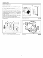
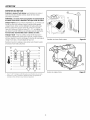
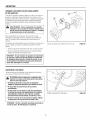
CHANGETHESPARKPLUG
Remove the Snow Hood
1. Removethechokecontrolknob(A,Figure28).
2. Removethesafetykey(B).
3. Removethemountingscrews(A, Figure29).
4. Slowlyremovethesnowhood(B) Makesurethat theprimerbutton
hose(C)andtheignitionwire(D)arenotdisconnected.
5. Thesparkplug (E)cannowbe accessed.
6. Toinstallthe snowhood,first makesurethatthe primerbuttonhose
andtheignitionwireareconnected.
7. Mountthesnowhoodto theengineandsecurewith themounting
screws.
8. Connectthechokecontrolknob(A,Figure30) with thechokeshaft
on thecarburetor(B).Makesurethechokecontrolknobis properly
installed.If thechokecontrolknobis notinstalledcorrectly,thechoke
will notoperate.
9. Installthesafetykey(C).
RemovingtheSnowHood
Figure 29
i
ConnectingChokeControlKnob
SnowThrowerEngine
Figure 28
25
Figure 30
MAINTENANCE
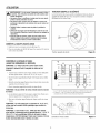
Checkand Replace Spark Plug
Checkthesparkplugeverytwenty-five(25) hours.Replacethesparkplug
(Figure31)if theelectrodes
arepittedor burnedor if theporcelainis
cracked.
1. Removesnowhood(see"RemovetheSnowHood"section).
\
2. Cleansparkplugandresetgapperiodically.
3. Cleanareaaroundsparkplug basebeforeremoval,to preventdirt
fromenteringengine.
4. Replacesparkplug if electrodesarepittedor burnedor if porcelainis
cracked.
5. Cleansparkplugby carefullyscrapingelectrodes
(do notsandblast
or usewirebrush).
6. Besuresparkplugis cleanandfreeof foreignmaterial.Checkelectrodesgapwitha wirefeelergaugeand resetgapto 0.030"(0.76ram)
if necessary.
7. Beforeinstallingsparkplug,coatthreadslightlywith graphitegrease
to insureeasyremoval.
ReplacingSparkPlug
Figure 31
8. Tightenplug firmlyinto engine.If torquewrenchis available,tighten
plug to 18-23ft-lbs (24.4-31.2Nm).
_
WARNING: Be certain to maintain proper ground
clearance for your particular area to be cleared.
Objects such as gravel, rocks, or other debris, if struck
by the impeller, may be thrown with sufficientforce to
cause personalinjury, propertydamage, or damage to
the snow thrower.
ARNING:Always turn unit off, remove ignitionkey,
and disconnectthe spark plug wire before making any
repairs or adjustments.
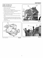
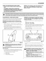
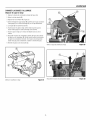
ADJUSTSKiD HEIGHT
Thissnowthroweris equippedwithtwo heightadjustskids,securedto the
outsideoftheaugerhousing.Theseelevatethefront ofthesnowthrower.
Whenremovingsnowfroma hardsurfaceareasuchasa paveddriveway
or walk,adjusttheskidsup to bringthefront ofthesnowthrowerdown.
Whenremovingsnowfromrockor unevenconstruction,raisethefront of
thesnowthrowerbymovingtheskidsdown.Thiswill helpto prevent
rocksandotherdebrisfrombeingpickedup andthrownbytheaugers.
To adjustskids, proceed as follows:
1. Placea block(equalto heightfromgrounddesired)underscraperbar
nearbutnotunderskid.
2. Loosenskid mountingnuts(A, Figure32)and pushtheskid down
(B) until it touchestheground.Retightenmountingnuts.
3. Setskid on othersideatsameheight.
NOTE:Make sure that snow thrower is set at same height on
both sides.
AdjustingSkidHeight
26
Figure 32
MAINTENANCE
BELTADJUSTMENT
TractionDrive Belt
Thetractiondrivebelthasconstantspringpressureanddoesnotrequire
anadjustment.If thetractiondrivebelt is slipping,replacethebelt. Seeauthorizeddealer.
Auger Drive Belt
If yoursnowthrower
will notdischarge
snow,checkthecontrolcableadjustment.If it iscorrect,thenchecktheconditionoftheaugerdrivebelt.If it is
damaged
or loose,replaceit (seeauthorized
dealer).
AugerDriveBeltAdjustment:
1. Disconnectsparkplug wire.
2. Remove
screw(A,Figure33)frombeltcover(B).Remove
beltcover.
3. Loosennuton idler drivepulley(A,Figure34)andmoveidlerdrive
pulleytowardsbeltabout1/8inch(3 mm).
WARNING: Do not over-tighten, as this may lift the
lever and causethe auger drive to be engagedwithout
depressingthe auger control.
AdjustingAugerDriveBelt
Figure33
CheckTensionon AugerDriveBelt
Figure34
4. Tightennut.
5. Withtheaid of anassistant,engagetheaugerdriveclutch.Checktensionon beltwhichis oppositeidler pulley(B,Figure34).Beltshould
deflectabout1/2 inch(12.5mm)with moderatepressure.Youmay
haveto moveidler pulleymorethanonceto obtainthecorrecttension.
6. Reinstallbeltcover(B, Figure33).Tightenscrew(A).
7. Attachthesparkplugwire.
NOTE:Wheneverbeltsareadjustedor replaced,thecableswill needto be
adjusted(see"CheckandAdjusttheCables"section).
CheckAugerDriveBelt:
1. Releasetheaugercontrollever.Theaugermuststopwithin5 seconds.
2. If augerdoesnotoperateproperly,stopengineandrepeat"Auger
DriveBeltAdjustment."
27
MAINTENANCE
BELT GUIDE ADJUSTMENT
1. Removesparkplug wire.
2. Havesomeoneengagetheaugerdrive.This will engageaugeridler
pulley(A, Figure35).
®
3. Measurethedistancebetweenthe beltguide(B)and belt(C).The
distanceshouldbeabout1/8inch(3 ram).
4. If adjustmentis necessary,
loosenbeltguidemountingbolt. Move
beltguideto thecorrectposition.Tightenmountingbolt.
5. Installbeltcover.
6. Connectsparkplugwire.
AdjustingBeltDrive
Figure35
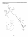
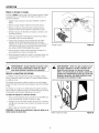
CHECKANDADJUSTTHECABLES
Thecablesareadjustedatthefactoryandnoadjustmentshouldbe
necessary.
If thecableshavebecomestretchedor aresaggingadjustment
will benecessary.
Wheneverbeltsareadjustedor replaced,thecableswill needto beadjusted.
Tocheckfor correctadjustment,unhook"Z" fitting (A,Figure36) atclutch
lever(B).
1. Moveclutchlever(B)to thefull forwardposition(justcontacting
plasticbumper).Holdingcabletight, notepositionof fittingto holein
clutchlever.
©
2. Thecenterof the"Z" fitting (A)shouldbebetweenthecenterandtop
of theholein theclutchlever(B).
Auger Drive Cable
[,_
orARNING:
flame. Drain the gasoline outdoors, away from fire
ChecktheCables
Figure36
AdjustingAugerDriveCable
Figure37
i
1. Removethegasfromthegastank.Standthesnowthrowerupon the
frontendof theaugerhousing.
2. Pushcable(A,Figure37) throughspring(B)to exposethethreaded
portionof thecable.
3. Holdsquareend ofthreadedportionwith pliersandadjustIocknut
(C) in or outuntil correctadjustmentis reached.
4. Pull cablebackthroughspringand connectcable.
28
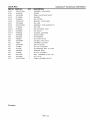
MAINTENANCE
TractionDrive Cable
1. Removethegasfromthegastank.Standthesnowthrowerupon the
frontendof theaugerhousing.
_
the gasoline outdoors, away from fire
orARNING:Drain
flame.
2. Loosenthebolts(A,Figure38)on eachsideof thebottompanel(B).
3. Removethebottompanel.
4. Disconnectthe"Z" fittingfrom thedrivelever(seeFigure36).
5. Slidethecableboot(A, Figure39) offthecableadjustmentbracket
)|1111|!_
(B) I
6. Pushthebottomofthetractiondrivecable(C)throughthecable
adjustmentbracketuntilthe "Z" hook(D)canbe removed.
7. Removethe"Z" hookfrom thecableadjustmentbracket.Movethe"Z"
hookdownto thenextadjustmenthole.
TractionDriveCable
Figure 39
CheckAdjustmentofTractionDriveCable
Figure 40
8. Pull thetractiondrivecableup throughthecableadjustmentbracket.
91Putthecablebootoverthecableadjustmentbracket.
10. Installthethe"Z" hookto thetractiondrivelever(seeFigure36)1
11. Tochecktheadjustment,depressthedriveleverand checkthelength
of thedrivespring(A,Figure40). Incorrectadjustment,thelength
of thedrivespringis a minimum3 inches(76 mm)anda maximum
3-3/8 inches185mm).
12. Installthebottompanel(B,Figure38)1
13. Tightenthebolts(A) on eachsideof thebottompanel.
AdjustingTractionDriveCable
Figure 38
29
MAINTENANCE
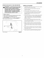
AUGERSHEARPiN REPLACEMENT
Theaugersaresecuredtotheaugershaftwith specialshearpinsthatare
designedto breakif an objectbecomeslodgedin theaugerhousing.Use
of a hardergradeshearpinwill reducetheprotectionprovidedbythe
shearpin.
,_
WARNING: Do not go near the dischargechute or auger
when the engine is running. Do not run the engine if
any cover or guard is removed.
Undermostcircumstances,
if theaugerstrikesan objectwhichcould
causedamageto theunit, theshearpin will break.Thisprotectsthegear
boxandotherpartsfrom damage.
Theshearpins(A, Figure41) arelocatedon theaugershaft.Replacea
brokenshearpinasfollows.
1. Tapoutthebrokenshearpin witha pin punch.
2. Installa newshearpin andcotterpin.Bendtheendsofthecotterpin
down.
ReplacingBrokenShearPin
Figure 41
CheckingTire Air Pressure
Figure 42
iMPORTANT:Do not replaceshear pins with anything other
than the correctgrade replacementshear pin. Use of bolts,
screws, or harder grade shear pins can result in equipment
damage.
CHECKTHETIRES
Checktires for damage.Checkthe air pressurein the tires with an
accurategauge (seeFigure42).
,_
CAUTION:Avoid Injury! Explosiveseparation of tire
and rim parts is possible when they are serviced
incorrectly.
,, Do not attempt to mounta tire without the proper
equipment and experience to perform the job.
,, Do not inflate the tires above the recommended pressure.
,, Do not weld or heat a wheel and tire assembly. Heat can
causean increasein air pressureresulting in an
explosion. Welding can structurally weaken or deformthe
wheel.
,, Do not stand in front or over the tire assembly when
inflating. Use appropriate tool that allows you to stand to
one side.
NOTICE:Check side of tire for maximum tire pressure. DO
NOT exceed maximum.
30
STORAGE
OFFSEASONSTORAGE
LUBRICATE
HE× SHAFTAND CHAINS
WARNING:Never store the engine, with fuel in the tank,
indoorsor in a poorventilated enclosurewhere fuel
fumes could reach an open flame, spark or pilot light
as on a furnace, water heater, clothes dryer, etc.
CAUTION:Do not allow grease or oil to contactthe rubber friction wheel or the disc drive plate, if the disc
drive plate or frictionwheel come in contactwith
grease or oil damage to rubberfriction wheel will resuit.
Handle gasoline carefully, it is highlyflammable and
careless use could result in seriousfire damage to your
person and/or property.
NOTICE:if grease or oil comesinto contactwith the disc drive
plate or frictionwheel, make sure to clean plate and wheel
thoroughlywith an alcohol base solvent.
Drain fuel into approvedcontainers outdoors, away from
open flame.
1. Positionspeedselectlever(A,Figure12) in first forwardgear.
If thesnowthrowerwill be storedforthirty (30) daysor moreatthe endof
thesnowseason,thefollowingstepsarerecommended
to prepareyour
snowthrowerfor storage.
2. Drainfuelto anapprovedcontainer.
3. Standthesnowthrowerup on theaugerhousingend.
NOTE:When the crankcaseis filled with oil, do not leave
the snow throwerstandingup on the auger housingfor an
extended periodof time.
NOTE:Gasoline must be removedor treated to prevent gum
depositsfrom forming in the tank, filter, hose, and carburetor
during storage.
4. Removethebottompanel.
1. Removegasoline,by runningengineuntil tankis emptyandengine
stops.If youdo notwantto removethegasoline,addfuelstabilizer
to anygasolineleft in thetankto minimizegumdepositsandacids.
If thetankis almostempty,mix stabilizerwith freshgasolinein a
separatecontainerandadd someofthemixtureto thetank.ALWAYS
FOLLOWINSTRUCTIONS
ONSTABILIZER
CONTAINER.
THENRUN
ENGINE
ATLEAST10 MINUTESAFTERSTABILIZER
ISADDEDTO
ALLOWMIXTURETOREACHCARBURETOR.
STORESNOW
THROWER
INSAFEPLACE.
5. Lubricatethechains(A, Figure43) witha chaintypelubricant.
6. Wipethehexshaft(B) andsprockets(C)with 5W30motoroil, before
storageand atthebeginningof eachseason.
7. Installthebottompanel.
2. Youcanhelp keepyourengine(4-cyclesonly)in goodoperating
conditionby changingoil beforestorage.
3. Lubricatethe piston/cylinder
area.This canbe donebyfirst removing
thesparkplugand squirtingcleanengineoil intothe sparkplug hole.
Thencoverthesparkplugholewith a ragto absorboil spray.Next,
rotatetheengineby pullingthestartertwoor threetimes.Finally,
reinstallsparkplug andattachsparkplugwire.
4. Thoroughlycleanthe snowthrower.
5. Lubricateall lubricationpoints(see"Lubrication"topicsin the
MAINTENANCE
section).
6. Makesureall nuts,bolts,andscrewsaresecurelyfastened.Inspect
all visible movingpartsfor damage,breakage,
andwear.Replaceif
necessary.
7. Touchup all rustedor chippedpaintsurfaces;sandlightly before
painting.
LubricateHexShaftandChains
8. Coverthebaremetalpartsof thesnowthrowerhousingauger,and
theimpellerwith rust preventative.
REMOVEFROMSTORAGE
Figure43
9. If possible,storeyoursnowthrowerindoorsandcoverit to give
protectionfromdustand dirt.
1. Puttheupperhandlein theoperatingposition,tightentheknobsthat
securetheupperhandle.
2. Fill thefueltankwith a freshfuel.
10. Onmodelswithfolding handles,loosentheknobsthat securethe
upperhandle.Rotatetheupperhandleback.
3. Checkthesparkplug.Makesurethegapis correct.If thesparkplug
is wornor damaged,replacebeforeusing.
11. If themachinemustbestoredoutdoors,block up thesnowthrower
andensuretheentiremachineis off theground.Coverthesnow
throwerwith a heavytarpaulin.
4. Makesureall fastenersaretight.
5. Makesureall guards,shields,and coversare in place.
6. Makesureall adjustments
arecorrect.
31
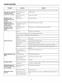
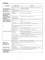
TROUBLESHOOT/NG
PROBLEM
LOOKFOR
REMEDY
Free-Hand
TM controlisACTIVE. Release
bothaugercontrolandtraction/Free-Hand
TM controlleversto stop auger.
Auger does not stop within
j5 secondsafter right
controllever is released.
Discharge chute or
deflectordoes not work
(electric).
Dischargechute or
i deflectordoes not work
i (remote-manual).
Drive fails to move
snowthrowerat slow
speeds.
Augerdrivebeltout of
adjustment.
Adjustaugerbelt.
Augerbeltguideoutof
adjustment.
Adjustaugerbeltguide.
Electricalfailure.
Seeauthorizeddealer.
Dischargechuteor deflectorout Adjustand/orlubricatecontrollinkage.
ofadjustmentor needs
lubrication.
Tractioncontrolout of
adjustment.
Readjustdrive,or selectspeedleversettingonespeedfaster.
Keyis off.
Pushkeyin to theONposition.
Failureto primea coldengine.
Pressprimerbuttontwiceand restart.
Fuelshut-offvalveis in CLOSEDTurnvalveto OPENposition.
position.
Outof fuel.
Fill fueltank.
ChokeOFF- coldengine.
TurnchokeON,setthrottleto FAST.
Engineflooded.
Turnchoketo OFF;try starting.
Nospark.
Checkgap.Gapsparkplug,cleanelectrode,or replaceplug as necessary.
Waterin fuel, or old fuel.
Draintank.(Disposeof fuel atan authorizedhazardous
wastefacility.)Fillwith
freshfuel.
Cordnot pluggedin or
malfunctions(ElectricStart
models).
Plugin cordor replacedefectivecord.
Fuelmixturetoo rich.
Movechoketo OFFposition.
Sparkplug faulty,fouled,or
gappedimproperly.
Cleanandgapsparkplug,or replace.
Fuelcapvent is blocked.
Clearvent.
Excessive vibration.
Loosepartsor damaged
impeller/auger,
Stopengineimmediately.
Tightenall hardware.If vibrationcontinues,havethe unit
servicedby anauthorizeddealer.
Snowthrower does not
stop when traction control
lever is released.
Tractioncontrolout of
adjustment.
Adjusttractioncontrollinkage.
Tirepressurenotequal.
Checktire pressure.
Onewheelis set in freewheelingmode.(Tractionlock
pin is in theOUTERhole.)
Makesuretheleft tractionlock pin is in theINNERholes(to engagethetraction
drive).
Enginefalls to start.
Enginestarts hard or runs
poorly.
Snowthrower veers to
one side.
32
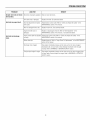
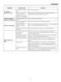
TROLIBLESHOOT/NG
PROBLEM
Scraper bar does not clean
hard surface.
LOOKFOR
Skidshoesimproperlyadjusted. Raiseor lowerskid shoes.
Drivebelt looseor damaged.
Unit fails to propel itself.
Unit fails to discharge
snow.
REMEDY
Replacedrivebelt.Seeauthorizeddealer.
Incorrectadjustmentof traction Adjusttractioncontrolcable.Referto "CheckandAdjusttheCables"in the
drivecable.
MAINTENANCE
sectionof this manual.
Wornor damagedfrictiondisc.
Replacefrictiondisc.Seeauthorizeddealer.
Augerdrivebelt looseor
damaged.
Replaceor adjustaugerdrivebelt.Referto "BeltAdjustment"in the
MAINTENANCE
sectionof this manual,or seeauthorizeddealer.
Augercontrolcablenotadjusted Adjustaugercontrolcable.Referto "CheckandAdjusttheCables"in the
correctly.
MAINTENANCE
sectionof this manual.
Brokenshearpin.
Replaceshearpin.Referto "AugerShearPin Replacement"
in the MAINTENANCE
sectionof this manual.
Dischargechuteclogged.
Stopengineimmediately.
Alwaysusetheclean-outtoolto cleara clogged
dischargechute,notyour hands.Cleandischargechuteand insideof auger
housing.Referto WARNINGS
in OPERATOR
SAFETYsection.
Foreignobjectlodgedin auger. Stopengineimmediately.
Alwaysusetheclean-outtoolto cleara cloggedchute,
notyourhands.Removeobjectfrom auger.Referto WARNINGS
in OPERATOR
SAFETYsection.
33
WARRANT/ES
Craftsman
Limited Warranty
General: Craftsman products are warranted to be free from defects in materials or workmanship for a specific time period
as set-out below (the "Warranty Period"). Warranties extend to the original purchaser of a Craftsman product only. Purchases made through an online auction or through any website other than www.sears.ca are excluded. The relevant Warranty Period commences on the original date of purchase. Within this period, Sears Canada, Inc. will, at its sole option,
repair or replace any products or components which fail in normal use. Such repairs or replacement will be made at no
charge to the customer for parts or labor, provided that the customer shall be responsible for any transportation cost.
Exclusions: This warranty does not cover failures due to normal wear, abuse, misuse, neglect (including but not limited to
the use of stale fuel, dirt, abrasives, moisture, rust, corrosion, or any adverse reaction due to improper storage or use
habits), improper maintenance or failure to follow maintenance guidelines and/or instructions, failure to operate the product in accordance with the owner's manual or any additional instructions or information provided at the time of purchase or
in subsequent communications with the original purchaser, accident or unauthorized alterations or repairs made or attempted by others. Also excluded from warranty coverage - except as provided below - are the following: maintenance,
adjustments, components subject to wear including but not limited to: cosmetic components, belts, blades, blade adapters,
bulbs, tires, filters, guide bars, lubricants, seats, grips, recoil assemblies, saw chains and bars, trimmer lines and spools,
spark plugs, starter topers and tines, and discoloration resulting from ultraviolet light. Any product missing the model
and/or serial number identification label will be disqualified from coverage under this warranty.
Repairs: Repairs have a 90 day warranty. If the defective product is still within the Warranty Period, then the new warranty
is 90 days from the date of repair or to the end of the original Warranty Period, whichever period is longer.
Disclaimers: THE WARRANTIES AND REMEDIES CONTAINED HEREIN ARE EXCLUSIVE AND IN LIEU OF ALL
OTHER WARRANTIES, WHETHER ORAL OR WRITTEN (OTHER THAN AS STATED HEREIN), AND WHETHER EXPRESS, IMPLIED OR STATUTORY, INCLUDING BUT NOT LIMITED TO ANY. THIS WARRANTY GIVES YOU SPECIFIC
LEGAL RIGHTS, WHICH MAY VARY FROM PROVINCE TO PROVINCE.
IN NO EVENT SHALL SEARS BE LIABLE FOR ANY INCIDENTAL, SPECIAL, INDIRECT OR CONSEQUENTIAL DAMAGES, WHETHER RESULTING FROM THE USE, MISUSE OR INABILITY TO USE THE PRODUCT OR FROM DEFECTS IN THE PRODUCT. THE EXCLUSIONS IN THIS PARAGRAPH SHALL NOT APPLY IN JURISDICATIONS
WHERE APPLICABLE LAW DOES NOT ALLOW FOR THE EXCLUSION OF INCIDENTAL OR CONSEQUENTIAL DAMAGES. IN SUCH JURISDICTIONS, THIS PARAGRAPH SHALL NOT APPLY, BUTTHE REMAINING PROVISIONS OF
THIS DOCUMENT SHALL REMAIN VALID.
Sears retains the exclusive right to repair or replace the product or offer a full refund of the purchase price at its sole discretion. SUCH REMEDY SHALL BE YOUR SOLE AND EXCLUSIVE REMEDY FOR ANY BREACH OF WARRANTY.
Customer Responsibilities:
In additional to complying with all suggested maintenance guidelines and instructions, customers' obligations shall include but shall not be limited to: operating the product in accordance with the owner's manual or
any additional instructions or information provided at the time of purchase or in subsequent communications to the purchaser from time to time, exhibit reasonable care in the use, operation, maintenance, general upkeep and storage of the
product. Failure to comply with these requirements will void any applicable warranty.
List of Applicable Warranty Periods: The following list contains the applicable Warranty Period for your Craftsman product and is based on a combination of the type of product or component and the intended and actual use of the product or
component:
1.
,
90 days: Craftsman products intended for use or actually used for commercial, institutional, professional or incomeproducing purposes.
2 years: Craftsman riding lawn mowers, yard and garden tractors, walk behind mowers, tillers, brush cutters, snow
blowers, handheld blowers, backpack blowers, hedge trimmers and electrical products for noncommercial, nonprofessional, non-institutional, or non-income-producing use, except for those components which are part of engine systems
manufactured by third party engine manufacturers for which the purchase has received an separate warranty with
product information supplied at the time of purchase.
34
WARRANT/ES
3.
1 year: Craftsman power cutters, stump grinders, pole pruners, gas chain saws, electric chain saws, trimmer attachments, baggers and pole saws for noncommercial, nonprofessional, non-institutional, or non-income-producing use.
4.
90 days: All defective batteries, which will be replaced during this g0-day Warranty Period.
,
60 days: Additional Warranty Period of 60 days will apply to adjustments and worn products or components BUT
DOES NOT INCLUDE WEAR OR ADJUSTMENTS for products used for commercial, institutional, professional or income-producing purposes. Wear items include but are not limited to: belts, blades, tires, spark plugs, air filters,
chains, shear bolts, skid plates, scraper bars, drift cutters, ropes, tines, collection bags and pulleys.
As the Warranty Period runs from the date of purchase and NOT from the date that a product is delivered, opened, assembled or first used, please ensure during this time period that your product or component has been assembled and
tested for correction operation regardless of when you intend to actually use it. Claims made after the Warranty Period
has expired will not be honored.
Proof of Purchase/Documentation:
Warranty coverage is conditioned upon the original purchaser furnishing Sears
Canada or its authorized third party service provider if applicable, with the original sales receipt or other adequate written
proof of the original purchase date and identification of the product. In the event that the original purchaser is unable to
provide a company of the original sales receipt, Sears Canada Inc. reserves the right to determine in its sole discretion
what other written proof of the original purchase date and identification of the product is acceptable.
Revision: 03/13/2009
Maintenance
Agreement
The Craftsman Warranty plus a Maintenance Agreement, provide maximum value for Sears products. Contact your nearest Sears store for details.
35
The California Air Resources Board, U.S. EPA, and Briggs & Stratton (B&S) are pleased
to explain the emissions control system warranty on your Model Year 2008 and later
engine/equipment. In California, new small off-road engines must be designed, built, and
equipped to meet the State's stringent anti-smog standards. B&S must warrant the
emissions control system on your engine/equipment for the periods of time listed below
provided there has been no abuse, neglect, or improper maintenance of your small
off-road engine.
Owner's
Manufacturer's
Warranty
As the engine/equipment
owner, you should however be aware that B&S may deny
you warranty coverage if your engine/equipment
or a part has failed due to abuse,
neglect, improper maintenance, or unapproved modifications.
at no cost
You are responsible for presenting your engine/equipment
to a B&S distribution
center, servicing dealer, or other equivalent entity, as applicable, as soon as a
problem exists. The warranty repairs should be completed in a reasonable amount of
time, not to exceed 30 days. If you have any questions regarding your warranty
rights and responsibilities, you should contact B&S at (414) 259-5262.
Coverage:
Small off-road engines are warranted for two years. If any emissions-related part on your
engine/equipment is defective, the part will be repaired or replaced by B&S.
The following are specific provisions relative to your Emissions Control Warranty Coverage.
Operator's Manual.
1.
Warranted Emissions Parts
It is in addition to the B&S engine warranty for non-regulated
The warranty on emissions-related
engines found in the
parts is as follows:
Coverage under this warranty extends only to the parts listed below (the emissions
control systems parts) to the extent these parts were present on the engine
purchased.
a.
Fuel Metering System
Cold start enrichment system (soft choke)
Carburetor and internal parts
Fuel pump
Fuel line, fuel line fittings, clamps
Fuel tank, cap and tether
Carbon canister
Any warranted part that is not scheduled for replacement as required
maintenance in the owner's manual supplied, is warranted for the warranty
period stated above. If any such part fails during the period of warranty
coverage, the part will be repaired or replaced by B&S at no charge to the
owner. Any such part repaired or replaced under the warranty will be warranted
for the remaining warranty period.
b.
Air Induction System
Air cleaner
Intake manifold
c.
Ignition System
Spark plug(s)
Magneto ignition system
Any warranted part that is scheduled for replacement as required maintenance
in the owner's manual supplied, is warranted for the period of time prior to the
first scheduled replacement point for that part. If the part fails prior to the first
scheduled replacement, the part will be repaired or replaced by B&S at no
charge to the owner. Any such part repaired or replaced under warranty will be
warranted for the remainder of the period prior to the first scheduled
replacement point for the part.
d.
Catalyst System
Catalytic converter
Exhaust manifold
Any warranted part that is scheduled only for regular inspection in the owner's
manual supplied, is warranted for the warranty period stated above. Any such
part repaired or replaced under warranty will be warranted for the remaining
warranty period.
Purge and vent line
e.
2.
Responsibilities:
As the small engine/equipment
owner, you are responsible for the performance of
the required maintenance listed in your owner's manual. B&S recommends that you
retain all receipts covering maintenance on your engine/equipment, but B&S cannot
deny warranty solely for the lack of receipts or your failure to ensure the performance
of all scheduled maintenance.
Your emissions control system may include parts such as the carburetor or fuel injection
system, fuel tank, ignition system, and catalytic converter. Also included may be hoses,
belts, connectors, sensors, and other emissions-related assemblies.
Where a warrantable condition exists, B&S will repair your engine/equipment
to you including diagnosis, parts, and labor.
Warranty
Add on or modified parts that are not exempted by the Air Resources Board
may not be used. The use of any non exempted add on or modified parts by the
owner will be grounds for disallowing a warranty claim. The manufacturer will
not be liable to warrant failures of warranted parts caused by the use of a non
exempted add on or modified part.
Air injection system or pulse valve
Miscellaneous Items Used in Above Systems
Vacuum, temperature, position, time sensitive valves and switches
Connectors and assemblies
Length of Coverage
Consequential
4,
For a period of two years from date of original purchase, B&S warrants to the original
purchaser and each subsequent purchaser that the engine is designed, built, and
equipped so as to conform with all applicable regulations adopted by the Air
Resources Board; that it is free from defects in material and workmanship that could
cause the failure of a warranted part; and that it is identical in all material respects to
the engine described in the manufacturer's application for certification. The warranty
period begins on the date the engine is originally purchased.
Engines that are certified to meet the California Air Resources Board (CARB) Emissions
Standard must display information regarding the Emissions Durability Period and the Air
Index. Briggs & Stratton makes this information available to the consumer on our
emissions labels. The engine emissions label will indicate certification information.
The Emissions Durability Period describes the number of hours of actual running time
for which the engine is certified to be emissions compliant, assuming proper
maintenance in accordance with the Operating & Maintenance Instructions. The
following categories are used:
Moderate:
Engine is certified to be emissions compliant for 125 hours of actual engine running time.
intermediate:
Engine is certified to be emissions compliant for 250 hours of actual engine running time.
Extended:
Engine is certified to be emissions compliant for 500 hours of actual engine running time.
For example, a typical walk-behind lawn mower is used 20 to 25 hours per year.
Therefore, the Ernissione Durabimity Period of an engine with an intermediate rating
would equate to 10 to 12 years.
Coverage
Coverage shall extend to the failure of any engine components
failure of any warranted emissions parts.
caused by the
Claims and Coverage Exclusions
Warranty claims shall be filed according to the provisions of the B&S engine
warranty policy. Warranty coverage does not apply to failures of emissions parts
that are not original equipment B&S parts or to parts that fail due to abuse, neglect,
or improper maintenance as set forth in the B&S engine warranty policy. B&S is not
liable for warranty coverage of failures of emissions parts caused by the use of
add-on or modified parts.
Briggs & Stratton engines are certified to meet the United States Environmental
Protection Agency (USEPA) Phase 2 emissions standards. For Phase 2 certified
engines, the Emissions Compliance Period referred to on the Emissions Compliance
label indicates the number of operating hours for which the engine has been shown to
meet Federal emissions requirements.
For engines less than 225 cc displacement.
Category C = 125 hours, Category B = 250 hours, Category A = 500 hours
For engines of 225 cc or more displacement.
Category C = 250 hours, Category B = 500 hours, Category A = 1000 hours
36
SPECIFICAT/ONS
ENGINE:
Brand
Briggs & Stratton
IVlodelSeries
Snow Series
GrossTorque*
13.50 T.P.@3060 rpm
Type
4-Cycle - OHV
Displacement
18.6 cu in. (305 cc)
Starting System
110V Electric, Recoil
Alternator
60W AC
Spark Plug Gap
Spark Ping
0.030 in. (0,76 ram)
481055
Long Life Platinum Spark Ping
5066
Oil Capacity
28 oz (0,83 liters)
Hydraulic Fluid
Fuel TankVolume
Mineral 5W30
ignition System
This spark ignition system complies with Canadianstandard ICES-002.
3.0 qts (2,8 liters)
AUGER/IMPELLER:
Clearing Width
27 in. (68,6 cm)
Intake Height
21 in. (53,3 cm)
Auger/Impeller Diameter
12 in. (30,5 cm)
3
Number of Impeller 8lades
CHUTE:
Chute Deflector
Manual
Chute Rotation
Left Side Crank- 190° (3.5 Turn)
DRIVESYSTEM:
Drive Type
Friction Disc - Traction Lock Pin
DriveSpeeds
6 Forward Speeds, 2 Reverse
Tire Size
16 x 4.8 in. (41 x 12,2 cm)
Tire Inflation
14 psi (0,96 bar)
EnginePowerRating Information
*The gross power rating for individual gas engine models is labeled in accordancewith SAE (Society of Automotive Engineers) code
J1940 (Small Engine Power & Torque Rating Procedure), and rating performance has been obtained and corrected in accordancewith
SAEJ1995 (Revision 2002-05). Torquevalues are derived at 3060 RPM; horsepower values are derived at 3600 RPM. Actual gross engine power will be lower and is affected by, among other things, ambient operating conditions and engine-to-engine variability. Given
both the wide array of products on which engines are placed and the variety of environmental issues applicableto operating the equipment, the gas engine will not develop the rated gross power when used in a given piece of power equipment (actual "on-site" or net
power). This difference is due to a variety of factors including, but not limited to, accessories (air cleaner, exhaust, charging, cooling, carburetor, fuel pump, etc.), application limitations, ambient operating conditions (temperature, humidity, altitude), and engine-to-engine
variability. Dueto manufacturing and capacity limitations, Briggs & Stratton may substitute an engine of higher rated power for this
Series engine.
37
38
RepairParts
PTS - 1
Engine
& Frame
Craftsman 27" Snowthrower C950-52943-O
NOTE: Unless noted otherwise,
use the standard hardware torque
specification chart.
37
22
20 \
21
/
I
/
/
24
25
40
23
\
16
44
31
36
\
29
13
SeeTraction
DriveGroup
/
PTS - 2
Engine
REF NO
Craftsman 27" Snowthrower C950-52943-0
& Frame
PART
NO.
QTY.
DESCRIPTION
1
20M1140141E1
1
ENGINE
2
6219MA
1
CORD, STARTER
5
002X97MA
4
BOLT, Carriage, 5/16-18 x 1-1/2
6
028X76MA
4
7
1960686SM
4
NUT, Speed, 1/4
NUT-HEX FLANGE.312-18
8
1501109MA
1
PULLEY, Engine
9
1922755SM
2
WASHER, Fiat, 3/8
10
11
1916965SM
1960428SM
1
1
WASHER, Locking, 3/8
CAPSCREW, Hex-Head, 3/8-24 x 1-1/4
12
1733324SM
1
V-BELT, Drive, 3L
13
585416MA
1
14
1733014SM
1
V-Belt, Auger, 4L
GUIDE, Belt
15
1917356SM
1
16
1921515SM
1
WASHER, Locking, 5/16
BOLT, Hex-Head, 5/16-24 x 3/4
17
1501112YZMA
1
ASSEMBLY,
18
1501065MA
1
BUSHING, Idler Bracket
19
53704MA
1
SPRING, Extension
20
1502120MA
1
IDLER, Plastic, Bail Bearing
21
1960251SM
1
NUT, Hex-Jam, 3/8-16
22
585781MA
1
BOLT, Carriage, 3/8-16 x 1-1/4
23
1501628YZMA
1
IDLER, Auger Assembly
24
1501200MA
1
SPACER, Auger Idler
25
1960027SM
1
WASHER, Fiat, 1/2
26
1733451SM
1
ASSEMBLY,
27
28
711682MA
1736381YP
1
1
PIN, Hair
PIN, Clevis
29
1740906ASM
1
PANEL, Bottom
30
1927429SM
4
SCREW, 1/4-20 x 5/8
31
165X159MA
1
SPRING, Extension
32
1740571 BNYP
1
33
1733583BNYP
1
FRAME, Steerable
ENGINE MOUNT
34
1924856SM
4
SCREW, 3/8-18 x 1/2
35
1664847SM
6
SCREW, 3/8-18 x 3/4
36
1741069MA
1
COVER, Belt Includes Ref. 44
37
695757
1
CAP, Pipe
38
696683
1
PIPE, Oil Drain
39
26X306MA
2
SCREW, Hex-Washer,
40
7023590SM
1
PIN, Cotter, 1/4, Self-Locking
41
794696
1
44
45
760539MA
761187MA
1
1
KEY, Ignition
LID, Toolbox Included with Ref. 36
ESNA
Idler Bracket
Spring Attachment
1/4 x 3/4, Self-Tapping
PAD, Foam
Footnotes
PTS - 3
Traction
Drive
Craftsman 27" Snowthrower C950-52943-0
NOTE: Unless noted otherwise,
use the standard hardware torque
specification chart.
29
/
11
6
8
i
10
10
18
24
4
/
2
34-54
Nm oi
27-40
ft.-Ibs,
1
PTS - 4
Traction
REF NO
Drive
PART
Craftsman
NO.
QTY.
27" Snowthrower
DESCRIPTION
1
579851MA
1
2
334163MA
4
CHAIN, Roller
RETAINER & BUSHING ASSEMBLY
4
1924856SM
8
SCREW, Hex Washer Head Taptite, 5/16-18 x 1/2
5
579868MA
1
CHAIN, Roller
6
11X30MA
5
7
1502105YZMA
1
RETAINER, Ring 7/16
SPRING LINK ASSEMBLY
8
1736469YP
3
9
10
1501090MA
1960027SM
1
7
WASHER, 1/2
11
1501092YZMA
1
AXLE, Swing Plate
12
1501563MA
1
13
01X193MA
1
AXLE, Bushing
BOLT, Hex 1/4-20 x 1-3/4 G8
16
1501089MA
1
SPROCKET, Axle
17
1501114MA
2
18
1501100MA
1
BEARING, Axle D-Hole
HEX SHAFT & SPROCKET ASSEMBLY
19
337029MA
1
HUB, Friction Wheel & Bearing
20
1501435MA
1
WHEEL, Friction
21
1921959SM
3
CAPSCREW,
22
1928372SM
3
NUT, Hex KEPS 1/4-20
23
1733326SM
1
RING, Retaining Extension
24
15X114MA
1
NUT, 3/8-24 Flange Lock
25
1501057YZMA
1
PLATE, Swinging
26
1501158MA
1
27
1501115MA
1
SPACER, Friction Pulley
FRICTION PULLEY ASSEMBLY
28
29
1501110YZMA
579944MA
1
1
30
1920397SM
2
BEARING, Flange
NUT, Hex Lock ESNA Light 1/4-20
31
1922837SM
1
CAPSCREW,
32
579860MA
1
SPOOL CABLE, Auger Control
33
1501059YZMA
1
BRACKET, Cable Spool
34
1501122MA
1
CABLE, Front Drive Lower AtI
SPRING, Extension
SPROCKET, Set
Hex Head 1/4-20 x 5/8 G5
SPEED SELECT ASSEMBLY
Hex Head, 1/4-20 x 1-1/2 G5
Footnotes
PTS - 5
C950-52943-0
Auger
Housing
Craftsman 27" Snowthrower C950-52943-0
NOTE: Unless noted otherwise,
use the standard hardware torque
specification chart.
482
/
499
490
484
/
527
485
480
522
523
491
J
\
525
493
J
522
523
\
500
Ref. Gear Case Assy
\
525'
527
524
510
\ \
541
514
540
544
PTS - 6
\
524
52O
Auger
Housing
REF NO
PART
NO.
Craftsman 27" Snowthrower C950-52943-0
QTY.
DESCRIPTION
480
583146MA
1
PULLEY, 4L 8.40 OD.
482
2001022MA
1
KEY, SQUARE 3/16 X 3/4
484
15X112MA
3
NUT, .50-20 HEXWDFLLK
485
1501158MA
1
SPACER, FRICTION PULLEY
490
582957YZMA
1
RETAINER, BALL BEARING
491
1705897SM
1
BEARING, BALL
493
001X45MA
3
499
500
710026MA
1737905BNYP
3
1
BOLT, HEX 5/16-18 X .62
NUT, 5/16-18 HEXWDFLLK
510
1740949AYP
1
BLADE, SCRAPER
511
7090799SM
5
BOLT, 1/4-18 X .75
514
710026MA
5
NUT, 5/16- 18
515
760040MA
2
PLUG, PANEL
520
1738044AYP
1
AUGER, ASSEMBLY,
LH
521
1738043AYP
1
AUGER, ASSEMBLY,
RH
522
9524MA
2
SCREW, 1/4-20 X 1.75
523
3943MA
2
SPACER, SLEEVE
524
73826MA
2
NUT, 1/4-20
525
53757MA
2
BEARING, FLANGE
527
25X021 MA
4
SCREW, 5/16-18 x 0.75
540
1737986AYP
2
SKID, HEIGHT ADJUST
541
340720MA
2
BOLT, 5/16-18 X .75
544
710026 MA
4
NUT, 5/16- 18
550
1736094YP
1
BRUSH, CLEANOUT
551
552
1736620YP
1960569SM
2
2
CLAMP, SPRING
SCREW
553
15X146MA
2
NUT
--
1501216MA
1
--
680230ZMA
1
KIT, SHEAR BOLT
WRENCH
HOUSING, ASSEMBLY
Footnotes
PTS - 7
Discharge
Chute
Craftsman 27" Snowthrower C950-52943-0
NOTE: Unless noted otherwise,
use the standard hardware torque
specification chart.
581
\
599
580
614
\,
592
614
606
602
Ref. Auger
PTS - 8
Housing
Page
Discharge
REF NO
Craftsman 27" Snowthrower C950-52943-0
Chute
PART
NO.
QTY.
DESCRIPTION
580
1736380HYP
1
CHUTE ASSEMBLY
581
305216MA
1
PIN
592
2860210SM
1
WASHER, PLASTIC
597
1501260MA
1
KNOB, T 3.00
599
002X97MA
1
BOLT, Carriage, 5/16-18 x 1-1/2
601
2X100MA
4
602
71071MA
4
CARRIAGE BOLT, 5/16-18 x 1.00
WASHER
603
606
71038MA
1501932YZMA
4
1
NUT, Hex, NyIock, 5/16-18
CHUTE COLLAR
607
02X101 MA
4
BOLT, CARRIAGE
609
15X145MA
4
610
1741917YP
1
NUT, 1/4-20 HEX NYLOCK
RETAINER RING INNER
611
1501282MA
1
RETAINER RING OUTER
613
7091530SM
4
BOLT, Carriage, Hex Flange Head, 1/4-20 x 3/4
614
5025391SM
4
NUT, Hex, NyIock Flange, 1/4-20
1/4-20 X 0.75
Footnotes
PTS - 9
Handle Assembly
Craftsman 27" Snowthrower C950-52943-0
NOTE: Unless noted otherwise,
use the standard hardware torque
specification chart.
766
739
\
735
720
\
739
738
\
740
738
721
722
723
724
_'x
728
765
/
/ /
730
751
731
/
_)
751
743
763
f
/
/
Ref. Engine
Page
759
745
PTS - 10
762
Craftsman 27" Snowthrower C950-52943-0
Handle Assembly
REF NO
PART
NO.
QTY.
DESCRIPTION
720
1741120AYP
1
HANDLE, UPPER
721
7288MA
1
SCREW, 3/8- 16 X 3
722
71072MA
2
723
71062MA
2
WASHER, FLAT
WASHER
724
71044MA
2
NUT, 3/8- 16
728
7289MA
2
STOP, PLASTIC
730
71007MA
1
731
732
71072MA
71062MA
1
1
SCREW, 3/8- 16 X 2
WASHER, FLAT
WASHER
733
71044MA
1
NUT, 3/8- 16
735
5146E701MA
1
HANDLE, RIGHT
736
5142 E701 MA
1
HANDLE, LEFT
737
760074MA
2
PIN, PIVOT CLUTCH
738
3535MA
2
NUT, PUSH ON CAP
739
4049MA
2
BUMPER, RECTANGLE
740
1502113MA
1
CABLE, DRIVE
741
761872MA
1
CABLE, AUGER CLUTCH
743
313441 MA
1
BRACKET, CABLE ADJUSTER
744
1673MA
1
SPRING, AUGER CLUTCH
745
15X145MA
1
NUT, 1/4- 20
750
1740580AYP
1
HANDLE, LOWER
751
25X021 MA
4
SCREW, TAP 5/16-18 X .75
759
579860MA
1
SPOOL-CABLE,
760
1501059YZMA
1
BRACKET, CABLE SPOOL YZ
762
763
1501122MA
001798MA
1
2
CABLE, LOWER DRIVE 12"
BOLT, HEX 1/4-20 X 1.5
765
308146MA
1
766
333928MA
2
BOOT, CLUTCH SPRING
GRIP
AUGRT CLUTCH
Footnotes
PTS - 11
Chute Rod
Craftsman 27" Snowthrower C950-52943-0
NOTE: Unless noted otherwise,
use the standard hardware torque
specification chart.
862
\
Ref. Handle Assy
/
860
863
\
\_
_
861
865
\
864
/
870
867
Ref. Auger Housing Assy
868
\,
,%
852=6
852-7__._ _._
/
852-3
PTS - 12
869
Chute Rod
REF NO
PART
Craftsman 27" Snowthrower C950-52943-0
NO.
QTY.
DESCRIPTION
852-1
1501533YZMA
1
852-2
164X37MA
1
852-3
1501067MA
1
852-4
017X48MA
1
GEAR, CHUTE ROTATION 9T
WASHER
852-5
579493MA
1
PIN, COTTER
852-6
1740591AYP
1
BRACKET, CHUTE GEAR
852-7
1501293MA
1
852-8
852-9
1501075YZMA
711682MA
1
1
PIN, HAIR
ASSEMBLY,
852-10
578060MA
1
PIN, UNIVERSAL JOINT
852-11
578309MA
1
PIN, CLEVIS
852-13
578063MA
1
HOUSING, UNIVERSAL
854
307399MA
1
855
309312MA
1
KNOB, SLEEVE
FLATWAS H ER
856
73664MA
1
860
1501456MA
1
NUT, PUSH ON 3/8"
EYE BOLT 3/8-16 X 6.00
861
148MA
1
GROMMET,
862
1501457MA
1
BOOT, EYE BOLT
863
71045MA
1
864
71072MA
1
NUT, 3/8- 16 HEXJAM
FLATWASHER .406 X .81 X .066
865
309344MA
1
ADAPTER, BOOT
867
71046MA
1
NUT, 3/8- 16 HEXNYL
868
02X101 MA
1
BOLT, CARRIAGE
869
15X145MA
1
NUT, 1/4-20
870
1501074YZMA
1
CRANK, ASSEMBLY CHUTE
ASSEMBLY,
SPRING
YOKE & ROD
YOKE ADAPTER YZ
PIN, HAIR
EYE BOLT
1/4-20 X 1.00
Footnotes
PTS - 13
Control Panel
Craftsman 27" Snowthrower C950-52943-0
NOTE: Unless noted otherwise,
use the standard hardware torque
specification chart.
779
735
761
766
765
760
771
763
764
77O
Ref. Handle Page
781
782
®
774
7!j
763
764
773
784
Ref. Handle
Page
8O9
808
810
812
811 _
PTS - 14
813
Control
Panel
REF NO
PART
Craftsman 27" Snowthrower C950-52943-0
NO.
QTY.
DESCRIPTION
735
71045MA
1
NUT, 3/8-16 HEXJAM
760
1741119AYP
1
BRACKET, SHIFT CONTROL
761
1931323SM
2
CARRIAGE BOLT, 1/4-20 x 2.00
763
71059MA
4
WASHER, SPLIT
764
71034MA
4
765
1741123BNYP
1
NUT, 1/4-20 HEX
CONTROL PANEL
766
3809MA
2
770
771
1741118AYP
302900MA
1
1
772
50786MA
1
SCREW, 5/16-18 X 1.75
SPRING
773
71071MA
1
FLATWAS H ER
774
71038MA
1
779
304437MA
1
NUT, 5/16-18 NYLON HEX
GRIP
781
71071MA
1
WASHER, FLAT .349 X .69 X .066
782
71081 MA
1
PIN, COTTER
784
1502019MA
1
ROD, SPEED CONTROL
805
71042MA
1
NUT, 5/16-24
806
6352MA
1
ADAPTER, SPEED ROD ASSEMBLY
808
50782MA
1
809
71060 MA
1
BALL JOINT, STEEL-YZ
WASHER
810
71042MA
1
811
579944MA
1
NUT, 5/16-24
FLANGED BEARING
812
1501110YZMA
1
ROD ASSEMBLY,
813
11X30MA
1
814
579858MA
1
RING, RETAINER
WASHER
CARRIAGE BOLT, 1/4-20 X .63
SHIFT LEVER ASSEMBLY
YOKE PANEL
Footnotes
PTS - 15
Decals
Craftsman 27" Snowthrower C950-52943-0
NOTE: Unless noted otherwise,
use the standard hardware torque
specification chart.
830
829
828
823
832
t\
835
825
PTS - 16
Decals
REF NO
Craftsman 27" Snowthrower C950-52943-0
PART
NO.
QTY.
DESCRIPTION
823
1737865YP
1
DECAL
DANGER CHUTE HAND
824
1737866YP
1
DECAL
DANGER FOOT
825
1741432MA
1
DECAL
CRAFTSMAN
829
1737870YP
1
DECAL
DRIVE CLUTCH
830
1737869YP
1
DECAL AUGER CLUTCH
831
1737872YP
1
DECAL
GEAR SELECTOR
832
48X5565MA
1
DECAL
CRAFTSMAN
1
DECAL
ID PLATE
835
1350/27
Footnotes
PTS - 17
Gear Case
Craftsman 27" Snowthrower C950-52943-0
NOTE: Unless noted otherwise,
use the standard hardware torque
specification chart.
340
326
/
320
/
306
321
/
322
/
/
310
/
323
324
\
316
304
301
305
314
/
310
300
303
PTS - 18
Gear Case
REF NO
PART
Craftsman 27" Snowthrower C950-52943-0
NO.
QTY.
DESCRIPTION
3OO
896MA
1
CASE, GEAR, RH
301
895MA
1
CASE, GEAR, LH
303
910828MA
7
SCREW, 5/16-24 x 1.00
304
71100MA
8
NUT, 5/16-24
305
330434MA
1
SCREW, 5/16-24 X 1.50
306
53749MA
1
PLUG, PIPE 0.25-18
310
780151MA
2
311
312
53743MA
53748MA
1
2
SEAL, OIL
BEARING, SLEEVE
WASHER, FLAT
313
760529MA
1
SHAFT, AUGER OUTPUT
314
897MA
1
315
53730MA
1
GASKET, GEAR BOX
WORM GEAR
316
73905MA
1
KEY, WOODRUFF
32O
53737MA
1
RING, QUAD 0.924 ID
321
583126MA
1
BEARING, FLANGE
322
48275MA
1
WASHER, FLAT
323
50684MA
1
BEARING, ROLLER
324
48275MA
1
326
50795MA
1
WASHER, FLAT
KEY
327
53732MA
1
WORM
330
53731MA
1
340
1740584AYP
1
BEARING, SLEEVE
IMPELLER
333431 MA
1
10oz TUBE LUBRIPLATE
#91
Footnotes
PTS - 19
Wheels
Craftsman 27" Snowthrower C950-52943-0
NOTE: Unless noted otherwise,
use the standard hardware torque
specification chart.
679
675
671
/
678
65O
655
652
676
Ref. Drive Page
/
655
671
/
673
680
PTS - 20
677
Wheels
REF NO
Craftsman 27" Snowthrower C950-52943-0
PART
NO.
QTY.
DESCRIPTION
650
1501563MA
1
652
1501089MA
1
SHAFT, AXLE
SPRKT & HUB
653
01X193MA
1
SCREW, 1/4-20 X 1.75
654
15X145MA
1
NUT, 1/4- 20 HEX NYLOCK
655
1501114MA
2
BEARING, AXLE
671
712120MA
2
WASHER, Fiat .765 x 1.12 x .06 YZ
673
1501138MA
1
675
676
1736778YP
577015MA
1
1
BUSHING, WHEEL
TIRE & RIM, RIGHT
677
15X145MA
1
NUT, 1/4- 20 HEX NYLOCK
678
1657528SM
1
RING, RETAINER
679
73842MA
1
PIN, KLIK .25 X 1.38 DIA
680
1736779YP
1
TIRE & RIM, LEFT
SCREW, 1/4-20 X 1.75 HH
Footnotes
PTS - 21
Headlight
Craftsman 27" Snowthrower C950-52943-0
NOTE: Unless noted otherwise,
use the standard hardware torque
specification chart.
621
620
622
626
623
Ref. Handle
631
/
625
628
1
1
624
627
629
630
634
PTS - 22
Page
Headlight
REF NO
Craftsman 27" Snowthrower C950-52943-0
PART
NO.
QTY.
DESCRIPTION
620
583490MA
1
621
762343MA
1
HOUSING, HEADLIGHT UPPER
HEADLIGHT ASSEMBLY *
622
1501514MA
1
HOUSING, HEADLIGHT
623
307781MA
2
SCREW, #8 X 1.75
624
1738347YP
1
WIRING HARNESS, HALOGEN
625
4029YZMA
1
BRACKET, HEADLIGHT
626
002X88MA
1
627
628
580527MA
71061MA
1
1
BOLT, CARRIAGE - 5/16-18 X 2.00
WASHER, SADDLE
629
71060MA
1
WASHER, SPTLK .31 X .58 X .08
630
15X144MA
1
NUT, 5/16-18 REGHEX
631
235MA
1
SCREW, 5/16-18 X 2.00
632
71060MA
1
WASHER, SPTLK
633
15X144MA
1
NUT, 5/16- 18 REGHEX
634
032618MA
1
TIE, CABLE
LOWER
WASHER, EXLK .32 X .60 X .040
Footnotes
Note* Forreptacement bulb, use Standard GE or Phillips #894.
PTS - 23
20Ml14-0141
-El
I 48SHORT
BLOCK
I I 1058
OPE_TO_'S
MANUAL 1329
REP'AOEMENT
ENG,_
] I 1330
R_PA,_
MANUAL
I
529
306
307
_
"f-
_s//
718A
eP
Assemblies
include
all parts shown
in frames.
Cylinder Assembly
Engine: Briggs & Stratton Model 20M114-0141-E1
Refi No.
Part No.
Qty.
1
2
794849
698340
1
1
3
391086s
15
45
46
48
219
220
691686
690977
795697
794910
693578
691724
1
1
1
1
1
1
306
307
697240
794822
1
1
529
791822
ReL No.
Description
Cylinder Assembly
Kit-Bushing/Seal
(Magneto Side)
Seal-Oil
(Magneto Side)
Plug-Oil Drain
Tappet-Valve
Camshaft
Short Block
Gear-Governor
Washer
(Governor Gear)
Shield-Cylinder
Screw
(Cylinder Shield)
Grommet
(Cylinder)
Valve Gasket Set-Reference 1095
Engine Gasket Set-Reference 358
MSC000099
Part No.
552
694674
718
690959
718A
695178
725
742
746
998
1058
1329
1330
1351
696756
692564
694679
792928
277104
20P4140015E1
276781
794847
1427
695757
Qty.
1
1
1
1
1
1
1
1
Description
BushingGovernor Crank
Pin-Locating
(Cylinder)
Pin-Locating
(Cylinder Head)
Shield-Heat
Retainer-E Ring
Gear-Idler
Pipe-Oil
Operator's Manual
Replacement Engine
Repair Manual
Stud
(Cylinder Shield)
Cap-Pipe
Carburetor Overhaul Kit-Reference
24
121
06/19/2009
20Ml14-0141
_
-El
177
287
24 <_
741
524
22
Assemblies
Crankcase
Engine:
Ref No
Part No
all parts shown in frames.
Cover, Crankshaft
Briggs & Stratton
Qty
Description
12
16
18
19
694953
794720
791965
698340
20
391086s
21
22
281658s
794825
1
1
24
25
222698s
792117
1
1
792144
1
793561
1
792073
1
26
include
1
1
1
1
Gasket-Crankcase
Crankshaft
Cover-Crankcase
Kit-Bushing/Seal
(PTO Side)
Seal-Oil
(PTO Side)
Cap-Oil Fill
Screw
(Crankcase
Cover/Sump)
Key-Flywheel
Piston Assembly
(Standard)
Piston Assemblu
(020 Oversize)
Ring Set
(Standard)
Ring Set
(020 Oversize)
Valve Gasket Set-Reference 1095
Engine Gasket Set-Reference 358
MSC000099
& Piston/Ring Assemblies
Model 20M114-0141-E1
Ref No
Part No
27
28
29
30
690975
696581
694691
694692
32
690976
146
177
690979
795015
287
699629
523
524
525
741
847
790477
691876
792041
691288
795087
Qty
Description
1
1
1
1
1
1
1
1
1
1
1
Carburetor Overhaul Kit-Reference
25
Lock-Piston Pin
Pin-Piston
Rod-Connecting
DipperConnecting Rod
Screw
(Connecting Rod)
Key-Timing
SeaI-O Ring
(Dipstick)
Screw
(Dipstick Tube)
Dipstick
Seal-Dipstick Tube
Tube-Dipstick
Gear-Timing
Dipstick/Tube
Assembly
121
06/19/2009
20Ml14-0141
-El
51A
914 ,_
51A
......................................................................................................................
35
1171
635
1026
45 (>
_
_-
337
_::::::::::S:: -.......
<:::..........
\)
Assemblies
include
all parts
shown
in frames.
Cylinder Head Assembly
Engine: Briggs & Stratton Model 20M114-0141-E1
Ref. No.
Part No.
5
7
794871
694872
13
794829
33
34
35
36
40
42
45
51
51A
122
192
499596
795199
694865
694865
690964
499586
690977
694874
694875
796315
690083
Qty.
1
1
1
1
1
1
1
1
1
1
1
1
1
Description
Ref. No.
Head-Cylinder
GasketCylinder Head
Screw
(Cylinder Head)
Valve-Exhaust
Valve-Intake
Spring-Valve
Spring-Valve
Retainer-Valve
Keeper-Valve
Tappet-Valve
Gasket-Intake
Gasket-Intake
Spacer-Carburetor
Adjuster-Rocker Arm
Valve Gasket Set-Reference 1095
Engine Gasket Set-Reference 358
MSC000099
Part No.
Qty.
337
635
798
691043
691909
697890
1
1
1
868
883
914
794086
695398
794827
1
1
1
1022
690971
1023
1026
1029
1100
1171
698042
695177
690972
791959
794828
1
1
1
1
1
Carburetor Overhaul Kit-Reference
26
Description
Plug-Spark
Boot-Spark Plug
Screw
(Rocker Arm)
Seal-Valve
Gasket-Exhaust
Screw
(Rocker Cover)
GasketRocker Cover
Cover-Rocker
Rod-Push
Arm-Rocker
Pivot-Rocker Arm
Stud
(Rocker Cover)
121
06/19/2009
20Ml14-0141
-El
472
187
1°9
i
O8
601
130
95
,_
\
127
_
117
_57
O
957A
105
............................
957
51A
51
51A
....................................
528
51
122
/
190
_,:_
1127
Assemblies
include
all parts shown in frames.
Carburetor and Fuel Supply Assemblies
Engine: Briggs & Stratton Model 20M114-O141-E1
Ref. No.
Part No.
Qty.
51
51A
95
694874
694875
690718
1
1
1
97
98
104
105
108
109
117
696387
695408
694918
696136
696736
793520
796080
1
1
1
1
1
1
1
118
796128
122
125
127
130
133
135
796315
796122
690727
696139
694914
698780
1
1
1
1
1
1
Description
Ref. No.
Gasket-Intake
Gasket-Intake
Screw
(Throttle Valve)
Shaft-Throttle
Kit-Idle Speed
Pin-Float Hinge
Valve-Float Needle
Valve-Choke
Shaft-Choke
Jet-Main
(Standard)
Jet-Main
(High Altitude)
Spacer-Carburetor
Carburetor
Plug-Welch
Valve-Throttle
Float-Carbuertor
Tube-Fuel Transfer
Valve Gasket Set-Reference 1095
Engine Gasket Set-Reference 358
MSC000099
Part No.
Qty.
137
187
698781
791879
1
1
190
699220
1
472
528
791948
793006
1
1
601
791850
1
633
690998
1
957
957A
795027
792647
1
1
972
975
1127
694260
698783
695407
1
1
1
Carburetor Overhaul Kit-Reference
27
Description
Gasket-Float Bowl
Line-Fuel
(Formed)
Screw
(Fuel Tank)
Knob-Choke Shaft
Hose-Primer
(Cut to
Required Length)
Clamp-Hose
(Green)
SealChoke/Throttle Shaft
(Throttle Shaft)
Cap-Fuel Tank
Cap-Fuel Tank
(Fresh Start)
Tank-Fuel
Bowl-Float
Screw
(Float Bowl)
121
06/19/2009
20Ml14-0141
604
-El
r-..................................................
564
604A
i
i
i
F_
\\
300
188 _
485
751
1230
883A
613A_
883
621
Assemblies
include
all parts shown
in frames.
Muffler and Controls Assembly
Engine: Briggs & Stratton Model 20M114-0141-E1
Ref. No.
Part No.
188
699479
190
699220
222
300
410
485
504
794800
794948
695382
695755
695383
564
699854
604
604A
613
790473
696758
794846
613A
794844
621
692310
Qty.
1
1
1
1
1
1
1
1
1
Description
Ref. No.
Screw
(Control Bracket)
Screw
(Fuel Tank)
Bracket-Control
Muffler
Link-Control
Knob-Control
Washer Set-Friction
(Control Bracket)
Screw
(Control Cover)
Cover-Control
Cover-Control
Screw
(Muffler)
(M6)
Screw
(Muffler)
(M8 Torx)
Switch -Stop
Valve Gasket Set-Reference 1095
Engine Gasket Set-Reference 358
MSC000099
Part No.
Qty.
632
695917
1
668A
694257
1
751
794839
1
773
694258
1
832
836
797095
699234
1
1
883
883A
1138
695398
794818
694255
1
1
1
1230
699847
1
Carburetor Overhaul Kit-Reference
2.8
Description
Spring/LinkMechanical Governor
Spacer
(Control Bracket)
Washer
(Stop Wire)
Retainer
(Control Bracket)
Guard-Muffler
Screw
(Muffler Guard)
Gasket-Exhaust
Gasket-Exhaust
Nut
(Control Bracket)
Stud
(Control Bracket)
121
06/19/2009
20Ml14-0141
-El
562
278 @
505
404
614
Assemblies
\,,_j
(_;_'
include
all parts shown in frames.
Governor Spring and Governor Lever Assembly
Engine: Briggs & Stratton Model 20M114-0141-E1
Ref. No.
Part No.
Qty.
209
694867
1
211
695307
1
227
694864
1
278
792008
1
404
795759
1
Description
Ref. No.
Spring-Governor
(Red)
SpringGoverned Idle
LeverGovernor Control
Washer
(Governor
Control Lever)
Washer
(Governor Crank)
Valve Gasket Set-Reference 1095
Engine Gasket Set-Reference 358
MSC000099
Part No.
Qty.
505
691251
1
562
793216
614
691620
1
616
795758
1
Carburetor Overhaul Kit-Reference
29
Description
Nut
(Governor
Control Lever)
Bolt
(Governor
Control Lever)
Pin-Cotter
(Governor Crank)
Crank-Governor
121
06/19/2009
20Ml14-0141
-El
37
78
%
326 _
1392
326 _
6_
Assemblies
include
all parts shown tn frames.
Blower Housing and Rewind Starter Assemblies
Engine: Briggs & Stratton Model 20M114-0141-E1
Ref. No.
37
55
Part No.
699047
696710
Qty.
1
1
58
65
693389
699851
1
1
65A
690837
78
695724
281
304
305
697268
795699
699480
1
1
1
306
326
697240
690837
1
1
456
458
459
592
692299
699334
281505s
690800
1
1
1
1
Gasket Set-Reference 1095
Engine Gasket Set-Reference
MSC000099
Ref. No.
Description
Guard-Flywheel
HousingRewind Starter
Rope-Starter
Screw
(Rewind Starter)
Screw
(Rewind Starter)
Screw
(Flywheel Guard)
Panel-Control
Housing-Blower
Screw
(Blower Housing)
Shield-Cylinder
Screw
(Rewind Guard)
Plate-Pawl Friction
Kit-Handle/Rope
PawI-Ratchet
Nut
(Rewind Starter)
Part No.
Qty.
597
691696
1
608
663
699335
699854
1
1
689
930
1036
691855
696709
1
1
1210
498144
1211
498144
1392
690800
Carburetor Overhaul Kit-Reference
Description
Screw
(Pawl Friction Plate)
Starter-Rewind
Screw
(Control Panel)
Spring-Friction
Guard-Rewind
Label-Emissions
(Available from a
Briggs & Stratton
Authorized Dealer)
Pulley/Spring
Assembly
(Pulley)
Spring/Pulley
Assemby
(Spring)
Nut
(Rewind Guard)
121
358
30
06/19/2009
20Ml14-0141
-El
23
\
/
%
1070
1005
'_
_
i
x
455
%
1070
Assemblies
include
332
all parts shown in frames.
Flywheel Assembly
Engine: Briggs & Stratton Model 20M114-0141-E1
Ref. No.
Part No.
Qty.
23
332
794812
794824
1
1
455
795011
1
Description
Ref. No.
Flywheel
Nut
(Flywheel)
Cup-Flywheel
Valve Gasket Set-Reference 1095
Engine Gasket Set-Reference 358
MSC000099
1005
1070
Part No.
Qty.
794815
794821
Carburetor Overhaul Kit-Reference
31
1
1
Description
Fan-Flywheel
Screw
(Flywheel Fan)
121
06/19/2009
20Ml14-0141
-El
474
727_
.....
851
851A(_
735
1009
Assemblies
include
all parts shown in frames.
Starter Motor and Ignition Assemblies
Engine: Briggs & Stratton Model 20M114-0141-E1
Ref. No.
309
333
334
356
474
578
727
732
Part No.
795909
492341
699477
793206
797090
792576
697465
699200
Qty.
1
1
1
1
1
1
1
1
Description
Ref. No.
Motor-Starter
Armature-Magneto
Screw
Wire-Stop
Alternator
Wire Assembly
Cover-Starter Drive
Screw
(Starter Drive Cover)
Valve Gasket Set-Reference 1095
Engine Gasket Set-Reference 358
MSC000099
Part No.
735
851
851A
1009
795901
692424
493880s
795012
1119
699772
Qty.
1
1
1
1
Carburetor Overhaul Kit-Reference
32
Description
Cord-Starter
Terminal-Spark Plug
Terminal-Spark Plug
Screw
(Starter Motor)
Screw
(Alternator)
121
04/19/2009
20Ml14-0141
-El
1196_
1288 '_
976
1318_i
11
163
610
668_4
731
1352_
1230_
1251A
1252
1251
Assemblies
include
all parts shown
\
in frames.
Snow Hood Assemblies
Engine: Briggs & Stratton Model 20M114-0141-E1
Ref. No.
Part No.
Qty.
11
53
696750
795017
1
1
163
528
692277
793006
1
1
610
668
794541
794539
1
1
731
731A
892
976
990
1196
794540
793621
791944
793382
794696
696692
1
1
1
1
1
1
Description
Ref. No.
Tube-Breather
Stud
(Carburetor)
Gasket-Air Cleaner
Hose-Primer
(Cut to
Required Length)
Arrester-lntake
Spacer
(Snow Hood)
Hood-Snow
Hood-Snow
Switch-Key
Primer-Carburetor
Key Set
Screw
(Snow Hood)
Valve Gasket Set-Reference 1095
Engine Gasket Set-Reference 358
MSC000099
Part No.
Qty.
1230
699847
1
1251
1251A
1252
696762
790471
699480
1
1
1
1288
794838
1
1318
698111
1
1352
795016
1
Carburetor Overhaul Kit-Reference
33
Description
Stud
(Control Bracket)
Shield-Snow
Shield-Snow
Screw
(Snow Shield)
Nut
(Snow Hood)
Nut
(Snow Hood)
Nut
(Spark Plug Shield)
121
06/19/2009
20Ml14-0141
-El
358 ENGINE GASKET SET
20
51
1022
163
1095 VALVE GASKET SET
868 ¢-_
1
883
Assemblies
Engine
Gasket
include
all parts shown
and Valve Gasket
in frames.
Set Assemblies
Engine: Briggs & Stratton Model 20M114-O141-E1
Ref. No.
Part No.
Qty.
3
391086s
1
7
694872
1
12
20
694953
391086s
1
1
51
51A
163
694874
694875
692277
1
1
1
Description
Ref. No.
Seal-Oil
(Magnetor Side)
GasketCylinder Head
Gasket-Crankcase
Seal-Oil
(PTO Side)
Gasket-Intake
Gasket-Intake
Gasket-Air Cleaner
Valve Gasket Set-Reference 1095
Engine Gasket Set-Reference 358
MSC000099
Part No.
Qty.
358
868
883
883A
1022
795201
794086
695398
794818
690971
1
1
1
1
1
1095
795200
1
Carburetor Overhaul Kit-Reference
34
Description
Gasket Set-Engine
Seal-Valve
Gasket-Exhaust
Gasket-Exhaust
GasketRocker Cover
Gasket Set-Valve
121
06/19/2009
20Ml14-0141
121 CARBURETOR
OVERHAUL
-El
KIT
127
_/
51A
i
163
105
633
Assemblies
include
__:_J
all parts shown in frames.
Carburetor Overhaul Kit Assembly
Engine: Briggs & Stratton Model 20M114-0141-E1
Ref. No.
51
51A
98
104
105
121
Part No.
694874
694875
695408
694918
696136
796137
Qty.
1
1
1
1
1
1
Description
Ref. No.
Gasket-Intake
Gasket-Intake
Kit-Idle Speed
Pin-Float Hinge
Valve-Float Needle
KitCarburetor Overhaul
Valve Gasket Set-Reference 1095
Engine Gasket Set-Reference 358
MSC000099
127
137
163
633
Part No.
690727
698781
692277
690998
Qty.
1
1
1
1
Carburetor Overhaul Kit-Reference
35
Description
Plug-Welch
Gasket-Float Bowl
Gasket-Air Cleaner
SealChoke/Throttle Shaft
(Throttle Shaft)
121
06/19/2009
Hardware identification& TorqueSpecifications
Common Hardware Types
Torque Specification Chart
Hex Head Capscrew
FOR STANDARD MACHINE HARDWARE (Tolerance + 20%)
Washer
Lockwasher
Carriage
_raardde
ware
Bolt
G
0
SAE Grade2
[(((((((((((((((((((
O
O
Hex Nut
Size Of
Hardware
in/Ibs
ft/I bs
Nm.
Q
SAEGrade 5
in/Ibs
ft/Ibs
SAEGrade8
Nm.
ft/I bs
Nm.
3.4
3.5
4.9
5.5
10.9
13.6
23.1
25.8
40.8
47.6
68.0
74.8
102.0
122.4
149.6
163.2
204.0
244.8
353.6
408.0
544.0
598.4
788.8
870.4
41
43
60
68
12
14
25
27
45
50
70
80
118
128
158
178
228
248
386
428
688
668
968
1,088
4.6
4.9
6.8
7.7
16.3
19.0
34.0
34.0
61.2
68.0
95.2
108.8
149.6
163.2
204.0
231.2
299.2
326.4
525.0
571.2
816.0
897.6
1,244.0
1,360.0
Standard Hardware Sizing
When a washer
or nut is identified
as 1/2", this is the
Nominal size, meaning the inside diameter is 1/2 inch; if a
second number is present it represent the threads per inch
When bolt or capscrew is identified as 1/2 - 16 x 2", this
means the Nominal size, or body diameter
is 1/2 inch; the
second number represents
the threads per inch (16 in this
example,
and the final number is the body length of the
bolt or screw (in this example 2 inches long).
The guides and ruler furnished
help you select the appropriate
below are designed
to
hardware
and tools.
m_
Nut, 1/2"
Inside
Diameter
m_
Screw,
m_
1/2 x 2 _;-
I
I
m_
8-32
8-36
10-24
10-32
1/4-20
1/4-28
5/16-18
5/16-24
3/8-16
3/8-24
7/16-14
7/16-20
1/2-13
1/2-20
9/16-12
9/16-18
5/8-11
5/8-18
3/4-10
3/4-16
7/8-9
7/8-14
1-8
1-12
19
20
27
31
66
76
11
12
20
23
30
35
50
55
65
75
90
100
160
180
140
155
220
240
2.1
2.3
3.1
3.5
7.6
8.6
15.0
16.3
27.2
31.3
40.8
47.6
68.0
74.8
88.4
102.0
122.4
136
217.6
244.8
190.4
210.8
299.2
326.4
30
31
43
49
8
10
17
19
30
35
50
55
75
90
110
120
150
180
260
300
400
440
580
640
NOTES
m_
Diameter(
B°dyL
|
m_
m_.o
_ength
/
1. These torque values are to be used for all hardware
excluding: Iocknuts, self-tapping screws, thread forming
screws, sheet metal screws and socket head setscrews.
2.
Recommended seating torque values for Iocknuts:
a. for prevailing torque Iocknuts - use 65% of grade 5
torques.
b. for flange whizlock nuts and screws - use 135% of
grade 5 torques.
3.
Unless otherwise noted on assembly drawings, all torque
values must meet this specification.
__@
_
m_
m4_.
Wrench & Fastener
1/4" Bolt or Nut
Wrench--7/16"
Size Guide
5/16" Bolt or Nut
Wrench--I/2"
3/8" Bolt or Nut
Wrench--9/16"
7/16" Bolt or Nut
Wrench
Wrench
PTS - 36
(Bolt)--5/8"
(Nut)--11/16"
1/2" Bolt or Nut
Wrench--3/4"
MAN
Manuel
d'uti;fisation
IVlod_le
C950-52943-0
13.5 T.P.
27 pouces
CHASS IGE
A
X PHAS S
!
Attention"
Lire et bien comprendre
ce manuel
avant d'utiliser
le chasse-neige.
Num_ro
de serie
Sears Canada inc., Toronto, Ontario M5B 2C3
Visit our Craftsman
website: www.sears.caJcraftsman
Manueln° 1738165
R6v.A
07/2009
Mercid'avoirachet6
cettesouffleuse
_ neige
Craftsman.
Nous
sommes
heureux
quevousayezplac6votreconfiance
danslamarque
Craftsman.
SivousutiHsez
etentretenez
ceproduitCraftsman
conform6ment
auxinstructions
dumanuel,
vous_ourrez
I'utiHser
pendant
denombreuses
ann6es.
Cemanuel
contient
desinformations
relatives
9.las6curit6
afinquevousconnaissiez
lesdangers
etrisques
qu=sontli6sauxsouffleuses
J.neige
etlafa?ondeles6viter.
Cettesouffleuse
_ neige
estcon?ue
etestdestin6
uniquement
pour61iminer
laneigeetnepeut_tre
utiHs6e
pouraucune
autreraison.
IIestimportant
quevousHsiez
etcompreniez
cesinstructions
enprofondeur
avantdetenterde
d6marrer
oud'utiliser
1'6quipement.
Un assemblage de finition est necessaireavant d'utiliser la souffleuse _ neige. Veuillezvous
reporter 9.la rubrique Assemblageafin d'obtenir ies directives pour I'assemblagede finition. Veuillez suivre attentivement les directives.
Sauvegardez cosinstructionspourvotre r6f_rence.
Souffleuse _ neige:
Num6ro de modele
R6vision
Num6ro de s6rie
JVJo|eur:
Num6ro de modele
R6vision
Num6ro de s6rie
Dale d'achal:
Adresse du magasin d'achal:
Ville:
Province:
T_l_phone:
REMARQUE:Noter los renseignementsci--dessouspour I'identification de la machineen cas de perle ou de vol.
TABLE
DESMAT/ERES
SI_CURITI_
DE L'OPI_RATEUR
.........................................................................
4
ASSEMBLAGE
...........................................................................................
10
OUTILLAGE
REQUISPOURL'ASSEMBLAGE
.............................................................................................
10
CONTENU
DEL'EMBALLAGE
....................................................................................................................
10
SACDEPIECESCONTENANT
..................................................................................................................
10
DBALLAGE..............................................................................................................................................
11
MONTAGE
DELAPOIGNEE
SUPERIEURE
ETDELA MANIVELLE
............................................................
12
VERIFICATION
DESCABLES
.....................................................................................................................
12
REGLAGE
DALA LONGUEUR
DESCABLES
.............................................................................................
12
MONTAGE
DELASELECTEUR
DEVlTESSE
.............................................................................................
13
MONTAGE
DELAGOULOTTE
...................................................................................................................
14
MONTAGE
DU PHARE
...............................................................................................................................
14
FONCTIONSETCOIVllViANDES
........................................................................
15
UTILISATION............................................................................................
17
AVANTD'UTILISATION
SOUFFLEUSE
_,NEIGE
.........................................................................................
17
UTILISATION
DELASOUFFLEUSE
A NEIGE
.............................................................................................
17
ARRETER
LA SOUFFLEUSE
A NEIGE........................................................................................................
18
TRACTION
GOUPILLE
DESORETE
...........................................................................................................
18
CONTROLER
LENIVEAUD'HUILE(AVANTDEDEMARRER
LEMOTEUR)
................................................18
REMPLIR
LERESERVOIR
D'ESSENCE
......................................................................................................
19
DEMARRER
LEMOTEUR
..........................................................................................................................
19
ARRETER
LE MOTEUR
..............................................................................................................................
20
DEGAGER
UNEGOULOTTE
D'EJECTION
OBSTRUEE
...............................................................................
21
CONSEILS
D'UTILISATION
........................................................................................................................
21
ENTRETIEN..............................................................................................
22
CONSEILS
D'ENTRETIEN
..........................................................................................................................
22
GRAISSAGE
DELABO'[TED'ENGRENAGE
DEVlS SANSFIN...................................................................
23
GRAISSAGE
DEL'ARBRE
DEVlSSANSFIN..............................................................................................
23
LUBRIFIER
LE PIGNON
DEROTATION
DEGOULOTTE
..............................................................................
23
ENTRETIEN
DUMOTEUR
..........................................................................................................................
24
CHANGER
LABOUGIED'ALLUMAGE
.......................................................................................................
25
REGLAGE
LAHAUTEUR
DESPATINS
.......................................................................................................
26
AJUSTEMENT
DESCOURROIES
...............................................................................................................
27
AJUSTEMENT
DUGUIDEDECOURROIE
..................................................................................................
28
CONTROLE
ETREGLAGE
DESC,_BLES
....................................................................................................
28
CHANGER
LESGOUPILLES
DECISAILLEMENT
DEVlSSANSFIN..........................................................
30
CONTROLER
LESPNEUS.........................................................................................................................
30
REIVIISAGE
..............................................................................................
31
REMISAGE
HORSSAISON........................................................................................................................
31
LUBRIFIER
L'ARBRE
HEXAGONAL
ETCHA/NES.......................................................................................
31
SORTIR
LASOUFFLEUSE
_,NEIGEDUREMISAGE
..................................................................................
31
DI_PANNAGE
............................................................................................
32
GARANTIES.............................................................................................
34
CARACTI_RISTIQUES
TECHNIQUES..................................................................
37
SECUR/TE BE L'OPERATEUR
,_
DAHGER- Risque d'amputatien
Le conduitd'6jection contJentun irnpuiseur
rotatif pour _jecter la neige. Ne d_bouchez ou
ne d_gagez jarnais le conduitd'_jection avec
vos mains. Les doigts peuventfacilernent _tre
pris pi_ge et une amputation tranrnatique ou
dilac_ration grave en r_suitera. Utilisez
toujours nn outil de nettoyagepour d6boucher
ou d6gager Jeconduitd'6jection.
Renseignementset symbolesde danger
Alerte de s_curit_ - Identifie I'inforrnationde
s_curit_ des dangers qni peuventr6sulter en
blessurecorporelle.
IVlanueld'utilisation - Lisezet cornprenez avant
route activit_ concernantI'ntilisation de la
souffleuse _ neige.
m
@
DANGER
,, Le contactdes mains avec I'irnpuiseurrotatif dans le
conduitd'6jection est Jacausela pluscommunedes
biessuresassoci_s avec des souffieuses_ neige.
,, Cette souffleuse _ neige pent arnputer Jesmains et les
plods, en plus des objets. Lisezet observez routes
instructionsde s_curit_ dans ce manuel. A d6faut de le faire
r6suitera _ la mort ou biessure grave.
Symboled'alerte de s_curit6 et rootsde signal
A
Le symbole d'alerte de s_curit6 _
et mot de signalisation
(DANGER,AVERTiSSEMENT,ATTENTIONou AVIS) sont utilis_s
pour indiquer la probabilit6 ou le potentiel de la gravit6 de
blessure corporelle et/ou dommage au produit. En plus, un
symbole de danger peut _tre utilis_ pour representer un type de
danger.
,_
DANGERindique un danger qui, si non _vit6, r6sultera
la mort ou blessure grave.
,_k
AVERTISSEMENT
indique un danger qui, si non _vit6,
pent r6suiter _ ia mort ou biessuregrave.
,_
ATTENTION
indiqueun
qui, si non _vit6, peut
r6sulter _ nne
blessuredanger
rnineure.
AViS indique une situation qui poutr6suJter en dornrnage
auprodnit
AVERTISSEMENT
IVlod_lesdes IL-U. : Certains cornposantset de sos
accessoires li_s dans ce prodnitcontients des produits
chirniquesconnus solon I'l_tat de Californie de causer le
cancer,des anomalies cong_nitalesou autre effet nuisible
la reproduction. Laver les mains apr_s la manipulation.
Certification "Cot _quipernent est conforrne aux exigences de
la norrneANSi B71.3-2005 relative aux souffleuses _ neige.
Irnpuiseurrotatif
Tari_re rotative
_F
De prudence,
soyez hers de la
pottle de la
souffleuse _ neige
rotatifs
ngrenages
N'essayez pas de
tendre le bras pour /_-_
prendrelos pi_ces
rotatives
0biers projet6s
Fen
Explosion
Choc
Vapeurstoxiqnes
Surface chaude
Protection des
oreilles est
recomrnand_e
pour Iongue dnr_e
d'ntilisation
Arr_tez le rnoteuret enlevez le connecteur de la
bougie d'allurnage avant de faire dn travail
d"entretien ou de r_paration.
AVERTISSEMENT
IVlod_iesdes I_.-U. : L'_chappernentdu rnoteurde cotappareil
contientdes produitschirniquesconnusscion I'[_tatde la
Californie de causer le cancer, des anomalies cong_nitales
ou autre offer nuisible _ la reproduction.
AVERTISSEMENT
iVlod_lesdes IL-U. : Les bornesde batterie, los extr_rnit_s
sorties, et ies accessoires li_s contientsdu plornbet des
cornposantsde piornb- produitschirniquesconnusde causer
le cancer et des anomalies cong_nitaiesscion i'l_tatde
Californie. Laver les mains apr_s la manipulation.
SECUR/TEBE L'OPERATELIR
Symbolesde commandesur Yequipement
Lecturedu manuel
DANGER
Huile
Carburant
Marche avant
Marche/Arr_t
Neutre
l+!
Volet de d6part
ferrn_
i×i
Volet de d6part
ouvert
u
Recuie
u
R1--
Arr_t
D_rnarrage
61ectrique Ernbrayer(vers le
bas) et d_brayer
(vers le haut)
Lent
Moteur =en rnarche
Vite
IVloteur- arr_t
Lisez,comprenez,etsuiveztous leeinstructionsur la
souffleuse_ neigeet le manueld'utilisationavantde faire
fonctionnereetappareil.
Lafaillite d'observerlesinstructionsdesdcuritddansce
manuelrdsultera_ lamort oublessuregrave.
. Soyezcompletement
familieraveclescommandeset I'usagenormaldela
souffleusea neige.
. Assurez-vousquevous _tesbienentra_n_
avantdefairefonctionnerla
souffleusea neige.
* Sachezcommentarr_terI'appareilet @clencherlescommandesrapidement.
. Nelaissezjamaisuneautrepersonnefairefonctionnerlasouffeuse_ neige
sanssurveillance.
. Suiveztoujoursles instructionsdansle manueld'utilisation,si lasouffleuse
neigeseraentrepos_epourunep6riodeprolong@.
,, Veuillezmaintenirou remplacerles6tiquettesde s_curit_etd'instructionssi
n_cessaire.
* N'essayez
jamaisdefairedesr@arationsmajeuressur lasouffleusea neige
moinsquevous_tesbien instruit.L'entretienina@quatde lasouffleuse
neigepeutr_sultera un fonctionnementdangeureux,
dommage
1'6quipement
et I'invalidationde la garantiedu produit.
Conduitd'6jecteur
J
D
Cornrnande de
traction Ernbrayer
(vers le bas)
--
=_"m
DANGER
Cornmande de
tari_re - Ernbrayer
(vers le has)
o_
Le conduitd'djectioncontientun impulseurrotatifpour
djecterla neige.Ned@ouchezou neddgagezjamais le
conduitd'djectionavecvosmains.Lesdoigtspeuvent
facilement@e prisesdansrimpulseur.Utiliseztoujoursun
outil de nettoyage.
La faillited'observerces instructionsdesdcuritdrdsultera
uneamputationtraumatiqueou dilacdratongrave.
-dr
Tari_re
d'embrayage
D_fiecteur de conduit
(haut et has)
POURDEGAGEREN TOUTESr:CURITEL'[:JECTEUR
BLOQUr:
A
Conduit
d'6jection
(gauche et droit)
Poign6es chauff_es
(haut et has)
ANGER' Le contactdespluscommune
mainsavecrimpulseurrotatifdansleconduit
d'djectionestlacausela
des blessuresassocidsavec
dessouffleuses_ neige.N'utilisezjamaisvos mainspour nettoyerle
conduitd'djection.
SUIVEZCESINSTRUCTIONS:
1. Arretezle moteur.
2. Attendre10 secondespour s'assurerqueleslamesde laturbinesesont
arr_t@sde tourner.
3. Utiliseztoujoursun outil de nettoyage,nonvosmains.
REMARQUE: Pas tous les syrnboles de cornrnandernontr_s
sur cette page appara'itra sur votre souffleuse_ neige.
Veuillez voir la section des CARACTERISTIQUES
ET
COMMANDESpour les symbolesappiicables.
Easy-Turn
TM Commande
detraction
TM
Free-Hand Commande
SECURITEDEL'OPERATEUR
S6curit6de 1'6quipementet de son fonctionnement
DANGER
ettesoufiJeu
neigeest een&nt
ei;op rateu; oui
s curit
Simal
.ut,isouemal
entretenue,
ceci tre
- dangereux.
Souvenez-vous
quevous_tesresponsablepour
votres6curit6et deceuxpr6sdevous.
* Gardezhorsde porteedu fonctionnementtoutespersonnes,en particulierles
petitsenfantet lesanimauxdomestiques.
,, Inspectezcompletement
I'endroitou la souffleusea neigeserautilis@et
enleveztous tapisd'accueils,les luges,lesplanchesa neige,lescordons
d'alimentationetautrescorpsetrangers.
,, Nefaitespasfonctionnerlasouffleusea neigesansporterdesvetementsde
neigeconvenables.
,, Le portde chaussuresamelioreralastabilitesur dessurfacesglissantes.
,, Soyezattentifpoureviterdeglisser ou detomberparticulierementIorsdu
fonctionnementde lasouffleusea neigeen marchearriere.
,, Nefaitespasfonctionnerlasouffleusea neigesansunebonnevisibilite ou
lumiere.Toujoursgarderun bonequilibreet tenirfermementlespoignees.
,, Ne@blayezpasla neigede lasurfacedespentes.SoyeztresprudentIorsdu
changement
de directionsur lespentes.Nepastenterde @blayerdes pentes
raides.
,, Nesurchargezpasla capacitede la machineen essayantde @blayerla neige
tropvite.
,, Nefaitespasfonctionnerlasouffleusea neigea unehautevitessede
tansportsur dessurfacesglissantes.Regardezderrierelasouffleuse_ neige
etsoyezprudentIorsdu fonctionnement
en marchearriere.
,, N'utilisezpaslasouffleusea neigesur dessurfacesaudessusdu solcomme
lestoits desresidences,lesgarages,lesverandasou toutesautresstructures
ou edifices.
o Lesoperateursdoivent@aluerleurabilite defairefonctionnerlasouffleuse
neigeen toutesecuritesuffisammentpour protegereux-m_meset lesautres
de blessures.
o La souffleusea neigeestconcuepourenleverla neigeseulement.N'utilisez
pasla souffleuse_ neigepourtouteautreraison.
o Netransportez
pas despassagers.
o Apr_savoirfrappeun corpsetranger,fermezle moteuraARRttT,@connectez
lecordondesmoteurselectriques,inspectezcompletementlasouffleuse
neigepour aucundommage,et r@arezledommageavantde recommencer
et defairefonctinnerlasouffleusea neige.
o Si lasouffleusea neigesecoussed'unemaniereanormale,fermezlemoteur
ARRttT.Toutevibrationestg@eralementun avertissement
de probleme.
Veuillezvoir un concessionnaire
ag@pourde reparationnecessaire.
o Pourdesmodelesmunisavecdesmoteursde @marrageelectrique,
@branchezlecordond'alimentation
apr_sla miseenmarchedu moteur.
Manutention de carburant
DANGER
Lecarburant
etsesvapeurs
sontextremement
flammables
et
explosifs.
Veuillez
bienprendre
soinavecpr_autiondu
carburant,
A d6fautd'observer
cesinstructions
des6curit6
peutcauser
unfeuouexplosion
quir6sultera
&desbrelures
gravesoula
mort.
LOBSDE L'ADDITJON
DUCABBUBANT
,' Arr_tezlemoteuret laissezrefroidirpour au moins2 minutesavantd'enlever
lebouchonde reservoirpour ajouterlecarburant.
,, Remplissezlereservoirdecarburantdehorsou dansun endroitbienventile.
,, Neremplissezpastrop le reservoirde carburant.PourpermettreI'expansion
deI'essence,ne remplissezpasau-dessusle basdu cou du reservoirde
carburant.
,, Gardezlecarburantloin desetincelles,desflammesnues,deslampes
temoins,dechaleuret d'autressourcesd'allumage.
,, Verifiezsouventleslignesdecarburant,lebouchonet lesaccessoirespour
fissureset fuites.Remplacez
si necessaire.
,, Utilisezun reservoirdecarburantapprouve.
,, Si le carburantrenverse,attendezjusqu'_ce qu'il soit vaporiseavantde
mettreen marchele moteur.
_JSE EN MABCHEDUMOTEUB
,' Assurez-vousquela bougied'allumage,lesilencieux,le bouchonde
carburantet filtre a air (si equippe)sonten placeet bienfixes.
,, Lorsquela bougied'allumageestenlevee,nemettezpasen marchele
moteur.
,, Si le carburantest renverse,n'essayez
pasde mettreen marchelemoteur
mais,@m@agezlasouffleusea neigeloin de lasectionde degatet@itezde
toutesourced'ignitionjusqu'_cequelesvapeursdecarburants'@apore.
,, N'amorcezpastrop le moteur.Suivezlesinstructionsdansce manuelpour
mettrele moteuren marche.
,, Si le moteurest noye,veuillezr@lerlevoletde depart(si equippe)a la
positionOUVERT/MARCHE,
@m@agerI'ac@lateur(si equippe)a laposition
VlTEet mettreen marchelemoteur.
LOBSDU FO_CT_O_NE_E_TD'EQUIPE_ENT
,' N'inclinezpas lasouffleusea neige_ un anglequi causelecarburantde
renverser.
,, N'etouffezpas lecarburateurpourarr_terlemoteur.
,, Si I'assemblaged'@urateur(si equippe)ou le filtre _air estenleve,ne faites
pasfonctionnerlemoteur.
LOBSDU CHA_GE_ENTD'HUILE
,, Si vousecoulezI'huiledu dessusdu tubed'huilede remplissage,lereservoir
decarburantdolt etrevideou le carburantpeuts'ecouleret peutresulteren
feu ou explosion.
LOBSDE LATBA_SPOBTATIO_
D'EQUIPE_E_T
,, TransportezIorsquele reservoirestVIDE,ou Iorsquelasoupaped'arretest
FERMEE.
LOBSDE L'ENTBEPOSAOE
D'ESSE_CEOU D'g:QWPEMEHT
AVECLE
CABBUBA_TDA_SLEB[:SEBVOIB
,' Entreposez
loin desfournaises,despo_les,deschauffe-eaux
ou autres
appareilsqui ont uneflammed'allumageou autresourced'allumagequi peut
allumerlesvapeursde carburant.
SECUR/TE BE L'OPERATELIR
Pi_ces amovibles
Enfants
DANGER
Gardezlesmains,tespie@et lesv_tementsJoindespi_ces
rotatives.Lespi_cesrotativespeuventcontacterou
enchev_trertesmains,lespieds,lescheveux,lesv_tements
ou accessoires.
A d6fautd'observercesinstructions
des6curit_r6sultera
uneamputationtraumatiqueou dilaceratongrave.
o Lorsdu nettoyage,
delar@arationoude I'inspection
de lasouffleuseaneige,
assurez-vous
quelemoteuresta lapositionARRItT,quelabougied'alhmageest
d6branch@
et quetoutespi@esamoviblessontarretees.
,, Neplacezpaslesmainsoules piedspresou [email protected]
loinde I'ouverturedelaconduiteentouttemps.
,, Nefaitespasfonctionnerlasouffleusea neigesansde protectionapprouves
et autresdispositifsde s@uriteen placeIorsdu fonctionnement.
,, Nelaissezjamaisvotresouffleusea neigesanssurveillanceIorsquele
moteurest en marche.Toujoursdebrayerlescommandesdeta@reet de
traction,arreterlemoteuret retirerlescles.
DANGER
Lesaccidents
tragiques
peuvent
arriv&s
si l'operateur
n'est
pasattentif&la presence
desenfants.
Lesenfants
sont
souvent
attir_ parla machine
etlesoufflage
deneige.Ne
jamaissupposer
quelesenfants
resteront
l&oQilsontete
vuspourladerni_,re
lois.
o Gardezlesenfantshorsde porteependantlefonctionnement.Lesenfants
sont souventattiresa I'@uipement.Soyezattentifdespersonnespresentes.
,, Soyezalerteet fermezI'appareilsiil y a desenfantstoutpres.
,, NelaissezjamaislesenfantfairefonctionnerI'appareil.
,, Prenezbiensoin Iorsquevousapprochezdescoinssansvisibilites,les
arbustes,lesarbresoules autresobjetsqui vouscachentlavue. Lesenfants
peuventOtrepresents.
S6curit6de moteur
DANGER
,, Assurez-vousquevosv_tementslachesne sontpasa laport@du devantde
lasouffleusea neigeet de [email protected],lesmitaines,lescordons
pendantes,lesv_tementslacheset pantalonspeuventrapidement_treprises
dansledispositifrotatifetuneamputationenresultera.Attachezlescheveux
longset enlevezlesbijoux.
Lefonctionnementsansdangerde la souffleuse_ neige
demandeun soin et entretienvigilant,A defautd'observer
lesinstructionsde securitedansce manuelresultera_ la
mortou blessuregrave.
,, Faitesmarcherla machinepour quelquesminutesapresle d@hargement
de
la neigepouremp_cherI'engelducollecteur/impulseur.
o Debrayez
tous lesvoletsde departet changezdevitesseau neutreavantde
fairefonctionnerle moteur.
,, Debrayez
la puissanceau collecteur/impulseur
Iorsquelasouffleusea neige
est transport@ou n'estpasutilis@.
,, Laissezlemoteurs'ajustera latemperature
exterieureavantdecommencer
dedeblayerla neige.
,, Utilisezunefiche trifilairemisa laterrepour toutessouffleusesa neigemuni
d'unmoteurd'entrainement
electriqueou d'un moteurde demarrage
electrique.
0bjets projet6s
DANGER
Lesobjetspeuvent
_treramasses
parlatari_reetprojetes
du
conduit.Nedechargez
pasla neigeverslesspectateurs
ou
permettre
quelqu'un
devant
la souffleuse
_ neige.A defaut
d'observer
cesinstructions
des6curite
danscemanuel
resultera
_ lamortoublessure
grave.
o Porteztoujoursdes lunettesde s@uriteou un ecranprotecteurpendantle
fonctionnementet Iorsd'un ajustementou reparation.
,, Soyezattentifde la directiond'ou [email protected] pres,
lesanimauxdomestiquesoules proprietespeuventetreendommages
par la
projectiondes objets.
,, Soyezattentifde votreenvironnement
pendantlefonctionnementde la
souffleuse_ neige.Si vous passerpardessusdesitemescommele gravier,
lestapisd'accueil,lesjournals,lesjouetset lespierrescach@ssousla
neige,touspeuventetreprojetesdu conduitou bloquesdanslatar@re.
,, SoyeztresprudentIorsdu fonctionnementsur ou traversantlesvoles
d'ac@s,lestrottoirsoules routesdegravel.
,, Ajustezla hauteurdu bottlerdecollectionpour degagerle gravelou toutes
autresma%resrocheuses.
,, Nefaitespasfonctionnerlasouffleusea neigepresdesenclosen vitre,des
voitures,despuits defenStreet desdescentessans lepropreajustementde
I'angledu conduitd'ejection.
,, Familiarisez-vous
avecI'endroitd'ou vousplanifiezde fairefonctionnerla
souffleuse_ neige.Marquezlesbornesdesvolesd'acceset destrottoirs.
DANGER
Lesmoteurs
degages
dumonoxyde
decarbone,
ungaz
toxiquesansodeuretsanscouleur.
Lefar derespirer
le monoxyde
decarbone
peutcauserdes
naus_s,desevanouissements
oula mort.
o Veuillezfairefonctionnerlemoteurdehors.
,, Nefaitespasfonctionnerle moteurdansun endroitenferme,memesi les
portesoules fen@essont ouvertes.
SECUR/TE BE L'OPERATEUR
S6curit6du moteur
suivre)
Efltretienet entreposage
AVERTISSEMENT
Lamiseenmarche
du moteurcr66eunegerbed'6tincelles,
L'6tincelle
peutmettrelefeuaugazinflammable
toutpr_s.
Explosion
etfeupeuenr6sulter.
* Si il y a unefuite de p6troleliqudi_ PLdansI'endroitou vousetes,n'essayez
pas defairefonctionnerlemoteur.
,, N'utilisezpasdesfhides sous pressionacausequelesvapeurssont
inflammables.
AVERTISSEMENT
,_hlllll!f_f!l,,
Lamiseenmarche
du moteurproduitdela chaleur.
Les
pi_cesdumoteur,
enparticulier
lesilencieux,
deviennent
extr_,mement
chaud.
A d6fautd'observer
cesinstructions
des6curit6
peutr6sulter
_idesbr01ures
thermiques
graves
aucontact.
* Netouchezjamaisun moteurou unsilencieuxchaud.Laissezlesilencieux,
lecylindrede moteuret lesailettesrefroidiravantde toucher.
,, Enleveztous d6brisdela sectiondusilencieuxet de lasectiondu cylindre.
,, Veuillezinstalleret entreteniren bon6tatlepare-6tincelles
avantd'utiliser
1'6quipement
sur uneterrebrutedecouverturedeforet,de gazonou de
brousse.
,, Mod_.les(:.-U.: C'estuneviolationducodesection4442 de laressource
public de la Californied'utiliserou defairefonctionnerun moteursur ou pres
d'uneterrebrutedecouverturedeforet degazonou de broussea moinsque
lesystemed'6chappement
estmunid'un pare-6tincelles
qui conformea la Ioi
localeou de I'l_tat.D'autresprovincesou zonesf6d6ralespeuventavoirdes
lois similaires.
Cettesouffleuse_ineigedolt e"trepropremententretenuepour
assurerun fonctionnement
et uneperformanceen toute
AVERTISSEMENT
s6curit6./!,d6fautd'observerlesinstructionsde s6curit6dans
ce manuelpeutr6sulter_ila mort ou unebleesuregrave.
,, Lorsde I'entretienou de la r6parationde lasouffleusea neige,arr_tezle
moteur,d6connectez
lefil de bougieet gardezlefil loin de la priseafin
d'empScher
quelqu'undemettreen marchele moteuraccidentellement.
,, V6rifiezlesboulonsd'obturateuretautrequincailleriesa phsieurs reprises
pourscellageafinquela souffleuse_ neigefonctionnedansdesconditions
s0r.
,, Gardezles6crouset lesboulonsserr6set gardezlasouffleuse_ neigeen
bon6tat.
,, Netouchezpas lesdispositifsde s6curit6.V6rifierr6gulierementleurbon
fonctionnementet r6parerle cas6ch6ant.
,, Lescomposantssontsujetsa s'user,s'endommager
eta se d6t6riorer.
V6rifiezfr6quemmentlescomposantset remplacezlespiecesrecommand6s
au besoin.
* V6rifiezlacommandede fonctionnement
fr6quemment.
Ajusteret r6parerle
cas6ch6ant.
,, Utilisezseulementdespiecesde remplacement
approuv6esIorsquevous
faitesdes r6parations.
,, Conformez
toujoursaveclessp6cificationsdu fabricantsur tousles r6glages
et ajustements.
,, Seulementlesconcessionnaires
ag66sdeservicedoiventetreemploy6spour
desservicesmajeureset desr6parationsn6cessaires.
,, Utilisezseulementdesaccessoires
approuv6sparlefabricant(tellesqueles
massespour roueset lesmassesd'6quilibrage).
,, N'essayez
jamaisdefairedesajustementspendantquele moteuresten
marche(a I'exceptionde la recommendation
sp6cifiquedu fabricant).
,, Nelaissezjamaisla graisseou I'huiledecontacterla rouede frictionen
caoutchoucou le disqued'entrainement.
Si ledisqued'entrainement
ou la
rouedefrictionviennenten contactaveclagraisseou I'huile,un dommage
la rouede frictionen caoutchoucr6sultera.
SECUR/TE
DEL'UT/L/SATEUR
,_k
Ce symboJesignale des consignesde s_curit_
irnportantes.II signifie" g<Attention! Prenezgarde !
Votre s_curit_est menac_e, g,
,&
AVERTISSEIVlENT
: Si desdtiquettesdes_curit_sontusdes
ou endommag_es
et nesont pluslisibies,commander
der
etiquettesde rechange
aupr_sdu concessionnaire
local.
Avantd'utiliserlasouffleuse_ neige,fireles6tiquettesdes6curitdappos6essurla souffleuse_ neige.Losavertissements
et misesengarde
visent_ prot_gerrutiiisateur.Pour6carterlesrisquesde blessure
corporelleou dedommagedela souffleuse_ neige,comprendre
et
respecter
toutesiesdtiquettesdesdcurit6.
B6f. 1737872
_=tiquetteVitesses
R_f. 1737889
Etiquette de la
commandode
tari_re
I
R6f. 1737870
Etiquette de la commandode traction
\
Etiquettes du moteur
Amputation
hazard
Contactwith moving paris inside
chute wiil cause serious injury.
= Shut off engine before unclogging
dischargechute.
* Else clean-out tool not hands]
Risque d'amputation
Toutcontactavec desg_bcesenrnouvement_I'intgrieur
de la go,lotto provoqueradegravesbJess_res.
d'djection.
Utiliser routg dedbgagement,pus les mains!
R_f. 278297
_A_I_Y
XXXXX.×XXXXXXXXXXX
Hum_rod'identification
du produit et _tiquette
du num_rode s_rie
(Arri_re du carter du
moteur)
Risque d'amputation
Amputation Hazard
° Tout contzci avec la
° contact with ae_er will
_ause serious in{ury.
o ]_eeg hands, _eet a_d
clolhiflg away.
= ](eep _yst_n_rs
away.
Thrown
Hazard
t_ri_re provo_uera de
graves hlessures.
Tenir vos pie_s, vos mai_s
et vSleme_ts _ dis4a_e.
o Tenir Je_spec_leurs b
dislance.
Dangerohjetsprojetbs
Objects
• He iamais diri_er _a
_hete en direction des
pe_onnes ou biens
mai_fiels.
=NeverdirecZ_ischarge
chutetowardspersons
orprope_y.
B_f. 1737888
AugerEtiquette
Dangervis sans fin
Oeadthe_perator's
mae_al {o_ egeratieg and
sa_eiy in_tructi_es.
Arr_ter Je moteur ei
reOre_ la cie _vani
Shut off engine a_g
re_ove key before
performingmaintenance
or_p_irworb,
Etiquettes de s_curit_
_
m
d'effedeertout_ntretien
outou_e_bp_ra0on.
,_,_,_
__
Figure I
ASSEMBLAGE
OUTILLAGE REQUIS POUR L'ASSEIVIBLAGE
CONTENU DE L'EIVIBALLAGE
122211-
11111-
Couteau
Clesde 1/2 pouce(ou des a molette)
Clesde 9/16pouce(ou clesa molette)
Clesde 3/4 pouce(ou clesa molette)
Clede3/8 pouce(ou ol5a molette)
Pinceou tournevis
Souffleusea neige
Recipientdestabilisateurdecarburant(dansle sacde pieces)
Goulotted'ejection
Manivelle
Sacde pieces
,_
COMMENT MESURER LES VJS
AVERTISSEMENT"Toujoursporter des lunettes de
securit_ ou autre protectionoculaire pour assembler la
souffleuse _ neige.
Longueur
Diametre
SAC DE PI[::CESCONTENANT
D©
* 2-1/4-20
* 2-1/4-20
x 1.75 Vis
* 2-Entretoise
Ecrou
* 2 - CI6s
1 - Pommeau
*Les piecesqui ne sontpasde montageet le cordond'alimentationsetrouvent
dansle sac_ pieceslivr6avecla souffieuse_ neige.Lespiecespeuvent8tre
gard6sdansla bo_e_ outils qui setrouveaudessusdu couvre-courroie_
10
ASSEMBLAGE
REMARQUE
: Lec8t6droitou gauchede lasouffleuse_ neigeest indiqu6
parrapport_ ia positionde rutiiisateurtenantia poign6e.
DEBALLAGE
1. A I'aided'uncouteau,coupezensuivantlespointill6sautourdu hautet
dufonddu carton.Puisretirezle cartonselonI'illustrationFigure2.
2. Rep6rez
et retirezle sacde piecesd6tach6es.
3. Retirezlesgoupillesdecisaillement,les boulonset lesentretoisesdu
sacde piecesd6tach6es
et rangez-lesdansla boTtede stockagedes
boulonsde cisaillement.
REMARQUE
: Mettezde c8t6le stabilisateurde carburantenattendant
d'ajouterde I'essencedansie r6servoir.Nousrecommandons
quele
stabiiisateurdecarburantsoit ajout6au carburant_ chaquefois que le
r6servoirestrempli.
4. D6gagezlasouffleusea neigedu cartonen la tirantpar la poign6einf6rieurepour lafairefouler.
ATTENTION
: NEPASrecuiersur lesc_bies.
Souffleuse 9 neige dans sa position d'exp6dition
Figure 2
Cgblesde commande d'embrayage
Figure3
5. Retirezle mat6rield'emballagede I'assemblage
depoign6e.
6. Coupezlesattachesretenantlesc_blesde commande
d'embrayage
la poign6einf6rieure.
REMARQUE
: Si lesc_iblessesont d6branch6s
desleviers
d'embrayage,
remontezlesc_blescommeillustr6Figure3.
11
ASSEMBLAGE
MONTAGEDELAPOIGNEE
SUPERIEUREET DELAIViANIVELLE
Manivelle
1. Desserrer
lesvis, lesrondellesplates,lesrondellesdeblocageet les
ecroushexagonaux
desorificesdu hautdela poigneeinferieure,sans
lesretirer(voir Figure4).
2. Retirertouteslesfixationsetle boulona oeilletde la manivelledes
trous inferieursdela poigneeinf6rieure.
Rondelle
plate
Boul
de
Ecrou de
//biocage
3. Souleverla poigneesuperieureetla mettreen positiondefonctionnement.Lapoigneesuperieuredevrait@rea I'exterieurdela poignee
inf6rieure.
Ron
REMARQUE:
S'assurerque iesc_blesnese prennentpasentreia
poigndeinferieureet la poigneesuperieure.
4. Remonterlesfixationset le boulona oeilletdela manivelledemontes
I'@ape2. Nevisserqu'unefois routeslesfixationsen place.
Be@on
& oeillet
Pi&,ce de
raccord
late
Rondelle plate
Montage de la poignee superieure
Figure 4
Montage de la manivelle
Figure5
V_rifier les cgbles
FigureB
5. Attacherlatigede la manivelle(A,Figure5) a I'ensembledu joint universel(B) avecla goupilleenepinglea cheveux(C).
6. SetterI'ecrousur le boulona oeillet.S'assurerquele boulona oeillet
estcorrectement
aligneet quela manivellepeuttournerlibrement(volt
Figure4).
7. Vissertousles boulonsde la poignee.
REMARQUE:S'assurer
quela manivellenetouchepar le couverciedu
carburateur.
VERIFICATION DES CABLES
1. Si les@blesdecommandesontdetachesdu cadredu moteur,lesrattachercommeindiqueFigure6.
2. Pourtout @@age
eve@u@,
voir "Verificationet@@age
des@bles"
dansla sectionENTRETIEN.
RI_.GLAGEDE LA LONGUEUR
DES CABLES
Les@blesd'entratnement
de tractionet d'entratnement
de la tariere(A etB,
Figure6) ontete@gleen usineet aucun@@age
dedevrait@renecessaire.
Cependant,
lots de la misedespoigneesen positionde fonctionnement,
les@blespeuvent@retroptendusoutrop I_ches.Dansle casoOun
@@age
s'averenecessaire,
consulterla rubrique"Verificationet @@age
des@bles"dansla sectionENTRETIEN.
12
ASSEMBLAGE
MONTAGEDELASI_LECTEUR
DEVITESSE
1. CouperI'attacheenplastique(A, Figure7) maintenantle selecteurde
vitesse(B)au supportdu selecteur(C).
2. %poserI'ecroude blocage(A, Figure8), la rondelle(B), le ressort(C)
etle boulon(D).
3. Placerle selecteurdevitessecommeillustreenFigure9.
REMARQUE:
Vuede I'int6rieur
de runiteIorsque
rutilisateuresten position
pourfairefonctionnerlechasse-neige
4. Reposerleboulon(D, Figure8), le ressort(C), la rondelle(B)et
I'ecroude blocage(A).
5. SerrerI'ecroude blocagejusqu'aceque 1/8a 3/16 po du boulondepassedeI'ecroudeblocage.
6. Visserle contre-ecrouhexagonal
3/8-16(E) posur le levier(F)jusqu'a
ceque I'ecrouatteintlafin du filetage.
1/8 a 3/16po de
filetsexposes
7. Visserle pommeauen plastique(G) le pluspossibleet s'assurerquele
pommeauestdirigevers I'avant.
8. SerrerfermementI'ecroude 3/8-16po contrele pommeau.
9. Deplacerle selecteura touteslesvitessespours'assurerde la bonne
tensiondu ressort.Si les61ecteur
secoincedanslesencoches,
desserrerI'ecroude blocagede 1/2 tourjusqu'acequele selecteurse
deplacepluslibrement.
Poign_edu s_lecteur de vitesses
Figure8
Selecteur
Support du
s_lecteur
Tableaude commande et support du s_lecteur
de vitesses
Levier de changement de vitesse et support
Figure 7
13
Figure9
ASSEMBLAGE
MONTAGE
DE LA GOULOTTE
REMARQUE
: L'ensemble
de ranneaude la chute(A) est install6sur
I'appareN
_ I'usine(Figure10).
1. Tournerla manivelle(Figure4)jusqu'acequela %chede la bagueext6rieure(B,Figure10)de I'anneaude la chutepointevers ravant.
REMARQUE:
S'assurerqueia fentedansI'anneaude la chutesoit align6e
avecia fiechesur i'anneauext6rieur,commeiNustr6.
2. Monterle d6flecteurde la chute(C)en passantlesvis (D) etles6crous
(E)danslestrouscommeillustr6.L'installationestadequateIorsquele
d6flecteurdechutepointeversI'avant.
3. Setterlesvis fermement,
en faisantattentiona ne pastrop lessetter.
MONTAGE
Montage de la goulotte
Figure18
Montage du phare
Figure11
DU PHARE
Le phareest montedu c0tedroit dela partiesup6rieuredu guidon.II est
posea I'enverspourlesbesoinsde I'exp6dition.
1. Retirer1'6crou(A,Figure11)et la rondelledeblocage(B)du boulon
t@eronde(C).
2. Releverle phare(D)a la partiesup6rieuredu guidon(E).S'assurer
quela rondelle(F) 6ventailet la rondelle(G)cintr6esontbienplac6es
commeillustr6en Figure11.
3. Poser1'6crouet la rondellede blocagepourfixer le phareauguidon.
Lepharedoit@redirig6vers I'avantdu chasse-neige.
14
FONCTION$ET COMMA/l/DES
®
1 -_-- [__-->
R1
®
n
I
©
®
_
"-__-Iillil
JJ
,1_
-tS-
®
Commandes de la soufleuse a neige
figure 12
C01VlIVlANDES
DELA SOUFFLEUSEA NEIGE
A.
D. Manivelle de rotationde !loulolle -- Serta fairepivoterla
goulotted'ejectionvers la gaucheou vers la droite.
E. I._crou_ oreilles de cornrnandede dellecteur-- Sert
contrOlerI'angledu deflecteurde goulotte(versle hautou le bas).
Levier du selecteur de vitesse-- Permetde choisirun rapport
devitesseparmilessix (6) en marcheavantetdeux(2) en marchearriere(voir Figure12).Pourchangerdevitesse,amenerle levierdu
selecteurdevitessejusqu'ala positionsouhaitee.
f. Ontil de nettoya!le-- Serta enleverla neigeet lesdebrisde la
goulotted'ejectionetdu carterde latariere.
FIEMAFIQUE
: Ne pas deplacer le levier de vitesse alors que
I'embraya!le de traction est en!la!le. Ceci peut !lravement
endornrna!lerle syst_',med'entrainement.
B°
C°
G. Plaque d'usure -- Utiliserpourajusterle gardeau sol du boTtier
detariere.
H. Phares-- Utiliserpourfairefonctionnerla souffleusea neigedans
desconditionsde pauvrevisibilit6.
Levier d'embraya!lede vis sansfin -- Serta engageret
debrayerlavis sansfin et laturbine.Serrervers lebaspourengager,
relQcher
pourdebrayer.
I. Bo'fle _!oulils -- Vousy trouverezdesgoupilles,boulonde
cisaillementetde cisaillementetdesentretoises.
Levier d'ernbraya!lede traction -- Serta faireavancerla
souffleusea neigeen marcheavantou arriere.Serrervers lebaspour
engager,
relQcher
pourdebrayer.
15
FONCTION$ET COMMANDES
®
I÷1I'-,I
®
®
Commandes de moteur
Figure 13
COlVlIVlANDES
DU IVlOTEUR
F°
A. Boutonde cornrnandedu volet de depart -- Utiliserpourfaire
fonctionnerle moteur(voirFigure13).
Interrupteur MARCHE/ARR[:T-- Utiliserpourmettreen marcheet
arreterle moteur.
G. Reservoirde carburantet bouchon-- Remplissez
le reservoir
peupres38 mm(1-1/2 po)dessousle hautdu coupour permettre
I'expansiondu carburant.
B. Beuten de dernarrageeleclrique -- Utiliserpourlamiseenmarche
du moteurenutilisantledemarreur
electrique.
H°
C. Beuten d'amerceur-- UtiliserpourinjecterI'essencedansle
manifolddu carburateurpourassurerun departrapidedansdes
temperatures
froides.
D. Ole de securite -- Doit etreinserepourfairefonctionnerlemoteur.
Retirezpourarreter.Netournezpasla clede securite.
E. Cordon de dernarreur-- Utiliserpourmettreenmarchele moteur
manuellement.
16
Bouchond'huile de rernpiissage(jauge d'huiie aliong_)
UTILISATION
AVANT D'UTILiSATiON SOUFFLEUSE A NEiGE
Contrgler ia visserie.V_rifier que routeia visserieest bien
serr_e.
REMARQUE: Cette sonffiense _ neigeest iivr_eAVECDEL'HUiLE
dans ie motenr. Voir les instructions_,Avantde d_marrer le
moteur ,, duns ia sectionUTILISATION
de ce manuel avant de
d_marrer ie moteur.
Lirele MANUELD'iNSTRUCTIONS
et iesS[_CURIT[_
DE
L'OPERATEUR
avant d'utiiiser ia SOUFFLEUSE
,_NEiGE.Comparer
iesillustrations
avecia sonffieuse_ neigepoursefamiiiariser
avec rempiacementdesescommandes
et r_giages.Conserverce
manuelpourrouteconsultation
uit6rieure.
AVERTISSEMENT:
L'utilisation
de route souffleuse
_ neigepoutprovoquer
ia projection
d'objets dunslosyeuxet
causerde gravesI_sions
ocuiaires.Toujours
porterdesiunettes
de s_curit_
ouautreprotection
ocuiaireavantd'utiliser
ia souffieuse
_ neige.Nousconseillons
ie
portde iunettesde s_curit_standardou d'un masquede s_curit_WideVisionpar-dessus
des iunettescorrectrices.
UTILISATIONDELA SOUFFLEUSEA NEiGE
REMARQUE:
Lorsdn ddneigement de neigeionrdeet hnmide,il
est conseill_de r_dnire ia vitessede d_placement, de maintenir
ie motenr _ plein r_gime et de ne pusd_gager ia neigesnr route
ia iargenrde ia machine.
L'utilisationla plusefficaceduchasse-neige
serad@ermin6e
parI'exp6rience,
entenantcomptedela natureduterrain,duventetde lapositiondesb_timents,enparticulierpourd@erminer
ladirectiond'@ection
dela neige.
REIVlARQUE:
Nepasprojeterla neigeversun b_timentcar des
corps6trangers ponrraient _tre pris par ia vissansfin et _ject_s
violemment.
5. Embrayer
lavis sansfin _ I'aidedela poign6ed'embrayage
(A,Figure
15),
VERSLEBAS- positionernbray6e
VERSLEHAUT- positionddbray6e
1. D6marrer
le moteur.
Voir _ D6marrer
le moteur,, dartscettesection.
6. Embrayer
lacommando
desrouesavecla poign6egauche(B).Lorsquele
chasse-neige
commence
_ sed6placer,
bienmaintenirlospoign6es
surle
guidonetguiderlechasse-neige
dansladirectionvoulue.Nepas
pousserle chasse-neige.
2. Tournerlamanivelle(A,Figure12)pour@glerI'orientation
(degauche
droite)dela goulotted'@ection.
3. R6glerleddlecteurdelagoulotte.Desserrer
I%rou(A,Figure14)
oreillessitu6surle c0t6dela goulotteetreleverdeddlecteurpour
augmenter
la distance
d'@ection
ou I'abaisser
pourdiminuerla distance
d'@ection.
SerrerI%rou_ oreilles.
7. Pourar@terled6placement
dela machine,
rel_cherla poign6ede
I'embrayage
desroues(B).
Leviersde commande
V6rifiezle d6flecteurde la chute
,_
Figure14
.
Pourar@ter
lavissansfin,rel_cher
lapoign_e
d'embrayage
delavissans
fin(A).
9. Pourfairereculerlasouffleuse
_ neige,placerle leviers@ecteur
devitesse
(A,Figure12)dansla premiere
ousecondeposition(R1ou R2)de
marcheartisteetengagerle levierdecommando
detraction(B,Figure
REiVlARQUE:
Ne pus pourraient_tre
projeter ia neige
vers
car
des
corps_trangers
pris
paruniab_timent
vis sansfin
et _ject_s violemment.
15).
NOTE: Always release the traction control lever before moving the
speed select lever.
_e
4. Lavitesse(A, Figure12) de d6placementest d@ermin6epar les conditions de la neige.Ohoisir lavitesseen d6pla_antle levierde vitessedans
la partiecolo@edu panneaucommeindiqu6ci-dessous.
1-2
3
4-5
6
Figure15
jamais taire tourner le moteur a I'_
ieur ou duns des endroits clos et mai ventil_s. Les gaz
d'_chappement du moteur contiennentdu IViONO×YDEDE
CARBONE,un GAZ INODOREet IVIORTEL.
* Garderies mains, los pieds, los cheveuxet los v_tements
ampies _ i'_cart des pi_ces en mouvement du moteur et de ia
souffieuse_ neige.
,, La temperature du silencieux et de sonvoisinage pout
d_passer 66 °C (150 °F). Evitercos zones,
Neigehumide,Iourdeet t@sprofonde
Neigemoyenne
Neiget@s16g_re
Position detransportseulement
,, NE PASiaisser d'enfants ni de jeunes adolescentsutiiiser ni
s'approcher de ia souffieuse _ neige durant ia marche.
17
UTILISATION
TRACTION GOUPILLE DE SURET! f:
,_L AVERTISSEIVlENT
: Life le manueld'instruction
avantd'utiliser
la machine.Uneutilisation imprudente
de cettemachinepout
s'av_rerdangereuse.
* Nejamaisutiiiser la souffleuse_ neigesanstoussoscapers,
grilleset autresprotections
en place.
* NejamaisdirigerI'_jectionversdesfen_tresni iaisser des
personnes
s'approcher
de la machinealorsque le moteur est
Ledroit detractiondesrouespeut_trecompletement
lib6reenutilisantla
goupille de s_ret_ (A, Figure16).Celapermeta I'unit_de led_placer
facilementaveclemoteurcoupe.
en marche.
* Toujours
arr_ter ie moteur avantde quitteria positionde
conduite.
* D_hrancher
la hougieavantded_houcher
ie carterdevissans
fin ou ia goulotted'_jectionet avantd'effectuer
desr_giagesou
r_parations.
* Avantdequitterla machine,enleveria cl_decontact.
Pour
r_duirele risquedefeu,garderia machine
propreet exempte
d'_clahoussures
d'essence,
d'huileet autresd_hris.
ARRETER LA SOUFFLEUSE A NEIGE
1. Rel_cher
lelevierdecommande
detraction(B,Figure
%.
2. Placerle commutateur
de ON/OFF
(A,Figure
22)enpositionOFF(Arret)et
sortirla cl6des6curit6(B).
Traction goupille de sOret6
CONTROLERLENIVEAUD'NUILE
(AVANTDEDi_IVlARRER
LEIVlOTEUR)
°C
oF
REiVlARQUF
: Le rnoteurest iivr_ d'usine rernpii d'huile.
ContrSler le niveaud'huiie. Completer le niveaule cas
6chaunt.
Figure16
86
*i
68
104
1. S'assurerque la machineest deniveau.Utiliserunehullo detergente
de hautequaliteclassee<<ServiceSF,SH,SJ, SL ou plus _.
32
50
2. Ouvrirlebouchon-jauge
d'huile(A,Figure17)etI'essuyer
avecun chiffon
propre
14
3. Remettrele bouchon-jauge
d'huileen placeettournerdansle sensdes
aiguillesd'unemontrepour serrer.
-4
.......
°22
4. Ouvrirle bouchon-jauge
d'huileetverifierle niveaud'huile.
REIVlARQUE
: Ne pus v_rifier le niveaud'huile durant la rnarche
du rnoteur.
Sous4 °C (40 °F) I'utilisationdeSAE30 r6sultera_ unedifficult6demiseen marche.
** Au-dessus27 °C (80 °F) I'utilisationde10W-30peutcauseruneaugmentationde
consomptiond'huile.V_rifiezleniveaud'huile plusfr_quemment.
5. Lecasecheant,ajouterdeI'huilejusqu'aurepereFULL(Plein)sur le
bouchon-jauge
d'huile.Nepasajoutertropd'huile.
6. Bienserrerlebouchon-jauge
d'huileapreschaquecontrOledu niveau
d'huile.
REIVlARQUE
: Par tr_s grand froid, au dessousde -18 °C (0 °F),
utiiiser une huiie rnoteur5W30 synth_tiquepourfaciiiter le
d6marrage.
REMARQUE: L'huiie rnoteurS.A.E. 5W30 peut _tre utilis6e
pour faciliter le d_rnarragepar des temperatures de =7_ =18°C
(20 _ 0 °F). L'huile synth_tique5W30 est utilisable _ toutes
temperatures.NE PASrn_iangerI'huile avec I'essence. Voir los
hullos recornrnand6es dunsie tableau ci-contre.
ContrOlerle niveau d'huile
18
Figure 17
UT/L/SAT/ON
REIVlPLIRLE Ri_SERVOIR
D'ESSENCE
AVERTISSEIVlENT
"L'essence
est inflammable,
Toujours
fake preuve (le precaution
pourmanipuler
ou entreposer
ressence. Couperle moteur et le laisserrefroi(lir pen(lantau
racine (leux minutesavant (l'ouvrir le bouchon(lu reservoir. He
pusverser(l'essence(fans le reservoir alors que la souffleuse
neiqeest en marche, chau(leou placeeclansun en(lroit ferme.
Rester_ I'ecart de flammes hUeSou (l'eUnceiieseiectriques et
HEPASFUIVlER
(lurant le rempJissage
(lu r_servoir. He jamais
compJ_tement
remplirle r6servoir (l'essence ; le rempiir
jusqu'_3,8 mm (1-1/2 pouces)(lu hautpourpermettrela
(liiatation (le ressence. Toujoursfake le piein (l'essence
rexterieur et utiiiser un entonnoir ou un bec verseurpoureviter
los (iChor(fomentsacci(lenteis. VeilJer_ essuyerroute
eclaboussure(l'essenceavant (le (lemarrer le moteur.
Cemoteurestcertifiepourfonctionnera I'essence.
Systemede contrOle
desemissionsd'echappement
: EM(modificationsmoteur).
Remplirlereservoird'essence
avecdeI'essence
automobile
ordinaireou super
sansplombou reformulee,fratcheet propre,d'indiced'octaneminimumde
85,en ajoutantun stabilisateurdecarburant(suivrelos instructionssur
I'emballage
du stabilisateurde carburant).NEPASutiliserd'essenceau
plomb.II estconseilled'ajouterdu stabilisateurdecarburanta I'essence
chaquefois que I'onajoutedeI'essenceau reservoir.
REMARQUE: L'essencede qualite hivernale est plus volatile
pour ameJiorer le (lemarrage. Verifier que le hi(ion est propre
et exempt (le routesalete et autres mati_res etrang_res. Ne
jamais utiliser (l'essence susceptible(l'_tre eventee suite _ une
conservationproiongeeclans le hi(ion.
,_
Conserverressence (fans un recipienthomoioguepropreet
gar(lerle bouchonen place sur le recipient. Gar(lerressence
clansun en(lroit frais et bien ventiie, jamaisclans la maison.
Pourgarantirsa voiatilite,ne jamais acheterplusde 30 jours
(le reserve(l'essence. L'essenceest (lestinee _ servirde
carburantpourmoteur _ explosion ; par consequent,ne pus
rutiiiser _ (l'autres fins. Beaucoup(l'enfants aiment I'o(leur (le
ressence, c'estpourquoieJJe(loit 0tre 0ar(leehorsde leur
porte,car elle (legage (lee valeurs(langereusesen cas
(l'inhalation, mais egalement explosives.
ATTENTION• HE PASutiiiser une essencecontenantune
queJconque quantite (l'alcool car cola presentedes
risques de (lommages graves(lu moteur ou de baisse
(le performances notable.
DEIVlARRER
LEiVIOTEUR
Demarrer le moteur (le la mani_re suivante :
Verifierque le niveaud'huilemoteurestsur le repereFULLdu bouchonjauged'huile.Le moteurde la souffleusea neigeestequiped'undemarreur
electriquea courantsecteuretd'un lanceura enrouleur.Avantdedemarrer
le moteur,veillera bien lire losinformationsci-dessous.
Sile moteurestnoye,placerle starteren positionOPEN/RUN
et lancerle
moteurjusqu'acequ'il demarre.
1. ContrOlerle niveaud'huile.Voir la section<<ContrOler/completer
le
niveaud'huile_ dansle MANUELDUMOTEUR.
2. S'assurerqueloscommandos
d'entratnement
de la machinesont
debrayees.
3. Placerle commutateur
de ON/OFF(A, Figure18) en positionON.
_k
AVERTISSEIVlENT"
Le (lemarreur eJectrique est
equipe (l'un cordon(l'alimentation _ trois file et
fiche compatibleavec le courantsecteur (lomestique.
Le cot(ion(l'aiimentation (loit 0tre en permanence
correctementrelic _ la torte pour ecarter le risque (le
(lecharge eiectrique pour I'utilisateur. Suivre los
instructionssuivantesavec attention :
Verifier que le circuit eJectrique de la maison est (le
type _ trois fils avec torte. Encas de (loute, consulterun
electricien agree. Si la maison ne comportepus de circuit
electrique _ trois fiis avec torte, ne pus utiiiser le (lemarreur
eiectrique. Si la maison comporteun circuit electrique
trois file avec terre mais qu'aucune prise n'est (lisponibie
pour brancher le (lemarreur eiectrique, fake installer une
prise avec torte par un eiectricien agree.
D6marrer lemoteur
Figure 18
4. Insererla cledesecurite(A,Figure19)dansle contactdu moteuret
renfoncercompletement
jusqu'enpositionde MARCHE.
5. Tournerle boutonde starter(B) completement
danslesonsdes
aiguillesd'unemontresile moteurestfroid.
_,_
_'_
REIVlARQUE: Ne pus utiliser le starter pour fake (lemarrer un
moteur chau(l.
toujoursraccor(ler(l'abor(lle cot(ionau bo'itier (le
J
commutateur
sur le
moteur, puisbrancher
I'autre boutsur J
AVERTISSEiVlENT
: Pourbrancher
le cot(ion(l'aiimentation,]
une prise (le courantavec torte.
J
6. Appuyerdeuxfois sur le boutond'amorcage(C).
REIVIARQUE
: Ne pus utiliser le bouton (l'amor(;age pour fake
(lemarrer un moteur chau(l.
AVERTISSEiVlENT
' Pour (lebrancher le cot(ion
(l'alimentation, toujours (lebrancher (l'abor(l le cote
branche sur la prise (le courantavec torte.
REMARQUE:Veiiier _ ce que la rallonge eiectrique est retire (lu
pouvoirrecipient.
19
UT/USAT/ON
9. Demarrage electrique : Appuyersurle bouton-poussoir
de
demarrage
(A,Figure21). Unefois quele moteura demarre,
debrancher
d'abordle cordonde la prisemuraleetpuisde la prise
pourcordond'alimentation(B).
Insererlacle desecurite
Figure19
7. Demarrage par lanceur : Tenirfermementla poigneedu cordonde
lanceur(A, Figure20). Tirer le cordondu lanceurlentementjusqu'a
sentiruneresistance,
puistirer rapidement.
Poigneedu cordonde lanceur
Figure 20
,_.AVERTISSEMENT : Un retraitrapidedu cordonde lanceur
(effet de rebond) peuttirer la main ou le bras versle moteur
avant d'avoir pu rel_cher le cordonet provoquerdes
fractures,contusionsou entorses. Pour d_marrer le moteur,
tirer le cordondu lanceurlentement jusqu'_sentirune
r_sistance puistirer rapidement pour_viter le rebond.
REMARQUE: Si le moteur ne d_marre pasau boutde trois
essais, voir la sectionD6pannagedu manuelde moteur.
8. Demurrage electrique : Brancherlecordonde rallonged'abord
sur la prisepourcordond'alimentationpuis sur uneprisemurale.
Si unerallongesupplementaire
estnecessaire,verifier qu'elleest de
typea trois fils.
Demarrage
electrique
Figure 21
iMPORTANT: Pourprolongerla dur_e de vie du d6marreur,
utiiiser des cyclesde d_marrage courts(cinqsecondes
maximum). Attendre une minute entre les cyclesde
demurrage.
AVERTiSSEIVlENT
: Si le cordonest endommag_, ii dolt
_tre remplac_ par le lubricant (ou son repr_sentant de
service apr_s-vente) ou par une personnequalifi_e afin
d'6carter tout danger.
REIVlARQUE
: Si le moteur ne d_marre pus au bout de trois
essais, voir la sectionD_pannage du manuel de moteur.
ARRETER
LE MOTEUR
Faire
tourner
lemoteur
pendant
quelques
minutes
pour
faire
evaporer
toute
humidite
presente
surlemoteur.
REMARQUE: Ne pus perdre la cJ_de contact/s_curit_.
Conserver la cl_ de contact/s_curit_duns un endroit sDr. Le
moteur ne d6marre pus sansla cl_ de contact/s_curit_.
,_.AVERTISSEIVlENT : L'essenceet ses vapeurssont
extr_mement inflammableset explosives. Le feu ou
I'explosion peuventprovoquerdes br01uresgraves
ou ia mort. HE PASutiliser le starter pour arr_ter le
moteur.
1. Placerle commutateur
deON/OFF(A,Figure22)enpositionde0%
2. Retirerlacledesecurite
(B).Conserver
lacledesecurite
horsdeportee
des
enfants.
D'arreter
lemoteur
20
Figure22
UT/L/SAT/ON
Di_GAGERUNE GOULOTTED'i_JECTIONOBSTRUi_E
CONSEILSD'UTILISATION
1. Ledeneigement
seferadefacond'autantplusefficaceque la neigeest
deblayeeimmediatement
apresetretombee.
AVERTISSEMENT
: Le contactdes mains avec la turbine
en rotation_ I'int_rieurde la gouiotte d'_jection est la
causela pluscourantede blessure associ_e aux
souffleuses _ neige. Jamais claire ou de d_sengorger
la goulotte d'_jectio avec vos mains, ou Iorsque le
moteur est en marche. Los doigts peuventdevenir
rapidement captureset I'amputationtraumatiqueou
des lac_r-ationsgraves peuventen r_suiter.
2. Pourenleverroutela neige,chevaucher
legerement
chaque
bande
precedemment
degagee.
3. Autantquepossible,projeterla neigedansle sensduvent.
4. Enmoded'utilisationnormal,reglerlespatinsa 3 mm (1/8 pouce)
sousle niveaudebarrede raclage.Sur lessurfacesde neigetres
compactee,
lespatinspeuventetreremontespourassurerun
deblaiement
efficace.
,, ARRETER
LEMOTEUR
!
reglerlespatins
5. Surlessurfacesde gravierou de pierresconcassees,
32 mm(1-1/4 pouces)sousle niveaude la barrede raclage(volt
_ Reglerla hauteurdespatins_ dansla sectionENTRETIEN
de ce
manuel).Lespierreset le graviernedoiventpasetreramassees
et
ejecteesparla machine.
6. Unefois I'operationde deneigement
terminee,laisserle moteur
,, Attendre10 secondesjusqu'_rarrgtcompletdeslamesde laturbine.
= Toujoursutiliserun outil de nettoyage,paslesmains.
Uneoutii de nettoyageestattachesoitau guidon,soitsurledessusdu
carterdevis sansfin(A,Figure23).UtiliserI'outil de nettoyagepour
eliminerla neigedu carterdevissansfin.
tournerauralentipendantquelquesminutespourfairefondrela neige
etla glaceaccumuleessur le moteur.
7. Nettoyerla souffleusea neigeavecsoinapreschaqueutilisation.
8. Nettoyerlesdepotsde neigeettousles debrisde I'ensembledela
souffleusea neigepuisla rincera I'eau(si possible)poureliminer
tout le seletautressubstances
chimiques.Essuyerla souffleuse
neige.
\\
\\
\\
\\
\\
\\
\\
9. Avantde demarrerla souffleusea neige,toujoursverifierI'absence
dansla vis sansfin et la turbinedeglaceou dedebrissusceptibles
d'endommager
la machine.
10.Verifierle n'iveaud'huileavantchaquedemarrage.
S'assurerquele
niveaud'huileestsur le repereFULLdu bouchon-jauge
d'huile.
Outilde nettoyage
Figure23
21
ENTRETIEN
RECOIVlMANDATIONS
DESERVICE
PROCEDURE
AVANT APRES CHAQUECHAQUE CHAQUECOMMENCEMENT
PREMIER
AVANT
CHAQUECHAQUE
5
10
25
DECHAQUE
5 HEURES
L'ENREPOSAGE
USAGE USAGE HEURES HEURES HEURES
SAISON
Verifiezque I'ailettede la
tarierearr_,tedans5
SF:CURITE
secondes
apresquele
levierdroitde commande
estrel_che
Lubrifiezlosleviersde
commando
ettringleries
V"
V"
V"
¢
Verifiezla souffleuse
neigepourquincaillerie
libre
,/
¢
LubrifiezI'arbrehexet les
chatnes
¢
Lubrifiezlosaccessoires
deI'arbrede la tariere
,/
du
SOUFFLEUSE LubrifiezI'engrenage
conduitde rotationet le
A NEIGE
mecanismdu ddlecteur
V"
Verificationde la
pressiondespneus
V"
Huile,verification
MOTEUR
,/
V"
Enleveztout la neigeet
neigefondantede la
souffleusea neigepour
empecherla tariereet les
commandes
de geler
Huile,changement
V"
,/
,/
,/
,/
,/
Verifiezet remplacez
la
bougied'allumage
V"
REMARQUE: La garantie sur cette souffleuse _ neige ne couvre
pas les it_mes sujets _ un abus ou ndgligencepar I'op_rateur.
Pour recevoir la valour en entier de la garantie, I'op_rateur dolt
maintenir la souffieuse _ neige solon los instructionsdans ce
manuel.
,&
LosRecommendationsde service ci-dessussont pouraider
I'operateur
a bienentretenirla souffleusea neige.
¢"
ATTENTION"Ne laissez jamais la graisse ou I'huile de
contacter la rouede friction en caoutchoucou le disque
d'entrainement. Si le disque d'entra'inement ou la roue
de friction viennenten contactavec la graisse ou
I'huile, un dommage _ la roue de friction en
caoutchoucr_sultera.
AVIS : Si la graisse ou I'huile vient au contact avec le disque
d'entra'inement ou la roue de friction, assurez-vous de nettoyer
le disque et la roue compl_tement avec un solvant_ base
d'alcool.
22
ENTRET/EN
GRAISSAGEDE LABO'iTED'ENGRENAGE
DEVIS
SANSFiN
LUBRIFIERLEPIGNONDEROTATIONDE GOULOTTE
Lubrifierlepignonde rotation degouiotte (A,Figure25)etarbre avec(B)
unehuiledetypeautomobile
touteslosvingt-cinq(25)heuresd'exploitation.
La botted'engrenage
devis sansfin estgraisseed'usineetne necessite
normalement
aucungraissagesupplementaire.
Si, pour unequelconque
raison,lagraisses'estvideoou suitea unereparationde la botte
d'engrenage,
ajouterde lagraisseLubriplateGR132ou equivalent.Utiliser
un maximum92 grammes(3-1/4 onces).
Ouvrirle bouchonde graissage(A, Figure24) unefois paran.Si lagraisse
estvisible,nerienajouter.Si la graissen'estpasvisible,utiliserun
morceaudefil deforen guisedejaugepourverifiers'il yen a dansla botte
d'engrenage.
LosgraissesMobiluxEP1et ShellAIvaniaEP1sont des
equivalents
acceptables.
Pignonde rotationdegoulotte
Graissagede la botted'engrenage
devis sansfin
Figure24
GRAISSAGEDE L'ARBREDEVIS SANSFiN
1. Utiliserunepompea graissemanuellesurlosgraisseurszerkde
I'arbredevis sansfin (B, Figure24) touteslosdix (10) heures
d'exploitation.Chaquefois qu'unegoupillede cisaillementest
remplacee,lavis sansfin (C)dolt IMPERATIVEMENT
etregraissee.
(Voir<<Changerlosgoupillesde cisaillementdevis sansfin >>
dans
cettesection.)
2. Pourle remisageou Iorsdu remplacement
de goupillesde
cisaillement,deposerlosgoupilleset lubrifierlosgraisseurszerkde
I'arbredevis sansfin (B) Fairetournerlavis sansfin plusieursfois
sursonarbreet remettrelosgoupillesdecisaillementen place.
23
Figure 25
ENTRET/EN
ENTRETiENDU iVIOTEUR
ContrSlerle niveaud'huile rnoteuravantde demarrerle moteuret
toutesles8 heuresd'utilisationcontinue.Ajouterde I'huilemoteur
preconiseele casecheant.
REIVlARQUE
: Un exc_',sd'huiie pent perturberle fonctionnernent
du rnoteur.Bien serrer le bouchon d'huiie pour6viter les fuites.
Changer i'huiie toutesles50 heuresd'exploitationou,au minimum,une
fois paran,memesi la souffleusea neigen'apaseteutiliseependant
cinquanteheures.Utiliserunehuile detergente
dehautequalitepropre.
Remplirle carterd'huilejusqu'aurepereFULL(Plein)de la jauge(A,
Figure26).VerifierqueI'huilea un indiceA.RI. <<SF_ ou superieur.Ne
pasutiliserd'huileSAE10W40(carla lubrificationpeutetreinsuffisante).
Voir les huiles recornrnand6es dans le tableau ci-contre.
Vidangeri'huiie - Placerla souffleusea neigedetellefaconquele
bouchondevidanged'huilesoit au pointle plusbas.Lorsquele moteur
estchaud,deposerle bouchondevidangeet lebouchonde remplissage
et
vidangerI'huiledansun recipientadapte(A,Figure27).
Contr61erle niveaud'huile moteur
Figure26
Remettrele bouchondevidangeen placeetbienserrer.Remplirle carter
d'huileavecI'huilemoteurpreconisee.
OF
104 "__
68 ........
°C
__:
..........................................
_
0
40
20
Bouchonde vidanged'huile
Sous4 °C (40 °F) I'utilisationdeSAE30 r_sultera_ unedifficult6de miseenmarche.
** Au-dessus27 °C (80 °F) I'utilisationde 10W-30peutcauseruneaugmentationde
consomptiond'huile.V_rifiezleniveaud'huile plusfr_quemment.
24
27
ENTRETIEN
CHANGERLA BOUGIED'ALLUIVlAGE
D6poserle capot_ neige
1. %poser leboutonde commande
de starter(A,Figure28).
2. Retirerla cle desecurite(B).
3. Deposerlesvis de fixation(A,Figure29)
4. Enleverlentementle capota neige(B).Verifierquele tuyaudu bouton
d'amoLcage
(C)et le cabled'allumage(D) nesont pasdebranches.
5. La bougie(E)esta presentaccessible.
6. Avantde poserle capota neige,verifierd'abordquele tuyaudu
boutond'amoLcage
et lecabled'allumagesontbranches.
7. Poserlecapota neigesur le moteuret I'attacher
aveclesvis de
fixation.
8. Raccorderle boutonde commande
de starter(A,Figure30) a I'arbre
de startersur le carburateur(B).Verifierquele boutondecommande
de starterest correctement
remonte.Si leboutondecommandede
startern'estpasposecorrectement,
le starternefonctionnerapas.
9. Remettreenplacela clede securite(C).
Moteurde souffleusea neige
Figure 28
25
Retirezle capotdesouffleusea neige
Figure 29
Raccorderleboutonde commande
de starter
Figure30
ENTRETIEN
R_gler ou changerla bougie
ContrOlerla bougie touteslesvingt-cinq(25)heuresde marche.Changer
la bouge(Figure31)si leselectrodessentpiqueesou brOlees
ou si la
porcelaineestfissuree.
1. %poser lecapeta neige(Voir lasection"DEPOSER
LECAPOTA
NEIGE).
\
2. Nettoyerla bougieetreglerI'ecartement
a intervallesreguliers.
3. Nettoyerlasurfacequi entourela basede la bougieavantde la
deposerafind'eviterde fairetomberde la saletedansle moteur.
4. Changerla bougiesi leselectrodes
sent piqueesou brOleesou si la
porcelaineestfissuree.
5. Gratteravecprecautionleselectrodes
de la bougie(ne pasnettoyer
parsablageni avecunebrossemetallique).
6. S'assurerque la bougieestpropreetexemptede toutematiere
etrangere.
VerifierI'ecartement
deselectrodesavecunejauge
d'epaisseuretle reglersur 0,76mm(0,030pouce)lecasecheant.Si
unebougieneuve,estrequise,voir la bougiede rechange
correcte
dansla sectionPIECESDERECHANGE
de cemanuel.
Changerla bougie
Figure 31
7. Avantderemonterla bougie,enduirelegerement
le filetaged'une
graissegraphiteepourassurerunedeposefacile.
8. Serrerfermementla bougiesurle moteur.Lecasecheant,utiliserune
cledynamometrique
pourserrera un couplede24,4a 31,2Nm
(18 a 23 ft-lbs).
,_
,&
AVERTISSEIVlEHT
' Toujourseteindre
la machine,
sortir
la cie de contactet
debrancherle c_ble
de la bouge
avant route operation d'entretienou de r_paration.
RL_GLER
LA HAUTEURDESPATINS
La souffleusea neigeestequipeede deuxpatinsde reglagede hauteur
fixessur I'exterieurdu carterdevis sansfin. IIs serventa releverI'avantde
la souffleusea neige.
AVERTISSEIVlEHT
: Veilier _ ce que la hauteur au sot
soit toujours adapt_e _ la surface _ d_neiger. Des
objets tels que du gravier, des pierres ou autres
d_bris, s'ils sent heurt_s par la turbine, peuvent _tre
projet_s avec suffisammentde force pour causerdes
blessures corporelles, des d_g_ts materiels ou des
dommagesde la souffleuse_ neige.
Pourdeneigerunesurfaceduretellequ'unealiceou unevoiede garage
goudronnee,
reglerlespatinsde manierea abaisserI'avantde la souffleuse
neige.
Pourdeneigerun sol pierreuxou inegal,abaisserlespatinsdemaniere
releverI'avantde la souffleusea neige.Cecipermetd'eviterquedespierres
etautresdebrissoientramassesetejectesparla vis sansfin.
Les patins se reglent de la mani_re suivante :
1. Placerunecale(d'epaisseur
egalea la hauteurau sol souhaitee)sous
la barrede raclagepres,maispasendessous,du patin.
2. Desserrerlesecrousde fixationdu patin(A, Figure32) et pousserle
patin(B) versle basjusqu'acequ'iltouchele sol. Resserrer
lesecrous
defixation.
3. Reglerle patinde I'autrecotea la memehauteur.
REIVlARQUE:V_rifier que la souffleuse_ neige est r6gl_e sur la
m_me hauteur des deux c0t_s.
Reglerla hauteurdespatins
26
Figure32
ENTRET/EN
AJUSTEIVlENT
DESCOURROIES
Courroie d'entrainementde traction
La courroied'entratnement
detractionsubit unepressionde ressort
constanteetne necessiteaucunajustement.
Si la courroied'entratnement
detractionpatine,changerla courroie.Consulterledistributeur
homologue.
Courroie d'entrainementde vissansfin
Si la souffleuse
a neigen'ejecte
pasdeneige,verifierle reglageducgblede
commande.
Si celui-ciestcorrect,verifieralorsI'etatdelacourroie
d'entratnement
devissansfin.Si elleestendommagee
ou detendue,
la changer
(consulterle distributeurhomologue).
Reglagede la courroied'entratnement
detariere:
1. Debrancherlefil debougie.
2. %poserlavis (A,Figure33)du protege-courroie
(B).%poserle
protege-courroie.
(b
3. DesserrerI'ecrousur le poulied'embrayage
devis sansfin (A,Figure
34)etdeplacerle poulied'embrayage
de vis sansfin vers lacourroie
de 3 mm(1/8 pouce)environ.
,_
Courroiedevis sansfin
Figure 33
Obtenirla tensioncorrecte
Figure 34
AVERTISSEMENT"Ne pas trop serrer car ceJapeut
reJever le levier et forcer I'engagement de
I'entraTnement de vis sans fin alors que la commande
de vis sansfin n'est pas actionnee.
4. Serrerrecrou.
5. AvecI'aided'unassistant,engagerrembrayagedevis sansfin (B,
Figure34).Verifierla tensionsur lacourroie(ducoteopposeaugalet
tendeur).Lacourroiedoitflechird'environ12,5mm(1/2 pouce)sous
unepressionmoderee.II peutetrenecessaire
de deplacerle galet
tendeurplusieursfois avantd'obtenirlatensioncorrecte.
6. Remontez
le couvre-courroie
(B, Figure33).Resserrez
lavis (A).
7. Attachezlecgblede bougied'allumage.
REMARQUE:
_,chaquelois quelescourroiessont regleesou remplac6es,
lescablesdoiventetreregles(voirlasection,, Verifiezetajustezles
c_ibles,,).
Verifiezla courroied'entratnement
de tariere:
1. Rel_chez
le levierde commande
de tariere.Latarieredolt s'arrgter
dansles5 secondes.
2. Si la tarierenefonctionnepascorrectement,
arretezle moteuret
recommencez
le <<Reglagedecourroied'entratnement
detariere>>.
27
ENTRET/EN
AJUSTEIVlENT
DU GUIDEDECOURROIE
1. Debrancherlefil debougie.
2. Faireengagerla commande
devis sansfin paruneautrepersonne.
Celaengagerla galettendeurde vis sansfin (A,Figure35).
®
3. Mesurerladistanceentrele guidede courroie(B)et la courroie(C).
La distancedoltetrecomprisentre3 mm(1/8 pouce).
4. Si unajustementest necessaire,
desserrerleboulondefixationdu
guidedecourroie.Placerle guidede courroiedansla positionqui
convient.Serrerle boulondefixation.
5. Poserleprotege-courroie.
6. Rebrancher
le fil debougie.
Reglageguidedecourroie
Figure35
VERIFICATION
ET REGLAGEDESCABLES
Lescgblessontreglesen usine.II estnormalement
inutilede modifierleur
reglage,saufencasd'etirementou dejeu tropimportant.
II faudraaussieffectuerle reglagedescgbleschaquefois quelescourroies
sontajusteesou remplacees.
Pourvdrifierle rdglage,detacherle crocheten "Z" (A,Figure36) du levier
d'embrayage
(B):
1. Pousserle levierd'embrayage
(B) completement
versI'avant(aucontactde la buteeen plastique).
2. Le centredu crochet(A)dolt etreentrele centreet lesommetdu trou
du levierd'embrayage
(B).
©
R6glage
,_
du ¢_ble de commande
des lames
Verifierlesc_bles
Figure 36
Reglagedu c_bled'entraTnement
devis sansfin
Figure37
ATTENTION!Vidanger ie r_servoir de carburant
I'ext_rieur et _ I'_cart de routefiamme.
1. Vidangerle reservoird'essence.
Basculerle chasse-neige
vers ravant
en le laissantreposersur lafaceavantdu carterdeslames.
2. Pousserle cgble(A,Figure37) dansle ressort(B) pourexposerla
partiefileteedu cgble.
3. TenirI'extremitecarreede la partiefileteeavecdespincesettourner
I'ecrou(C) dansun sensou dansI'autrepourobtenirle reglageapproprie.
4. Tirerlecgbledansle ressortet remonterlecgble.
28
ENTRET/EN
Reglage du c_ble de corflrnandede la traction
1. Viderlereservoir
d'essence.
Basculerlasouffleusea neigesur ravant
du carterdevis sansfin.
_k
AVERTISSEiVlENT"
Vidanger J'esseflce_ J'ext_rieur,
r_cart de feu ou de fJarnrnes.
2. Desserrerlesboulons(A, Figure38) dechaquecotedu panneau
inferieur(B).
3. Deposerlepanneauinferieur.
4. Retirerle crocheten "Z" du levierde commande
(voir Figure36).
5. Degagerlagainede cgble(A,Figure39) de la ferrurede reglagede
cgble(B).
6. Enfoncerle basdu cgblede commande
de traction(C)danslaferrure
de reglagede cgblejusqu'apouvoirdegagerle crocheten<<Z _ (D).
7. Sortirle crocheten <<
Z _ de la ferrurede reglagedecgble.Placerle
crocheten <<
Z _ dansletrou de reglagesuivant.
8. Tirerlecgblede commande
detractionversI'arrierede la ferrurede
reglagedecgble.
Cgblede commande
de traction
Figure39
P
9. Remettrela gainede cgblesur la ferrurede reglagede cgble.
10. Remonterle crocheten"Z" surle levierdecommande
(voir
Figure36).
11. Pourverifierle reglage,serrerle levierdecommandeetobserverla
Iongueurdu ressortdecommande(A,Figure40).Lorsquele reglage
estcorrect,la Iongueurdu ressortest de76 mm (3 pouces)minimum
85 mm(3-3/8pouces)maximum.
n
12. Poserle panneauinferieur(B, Figure38).
13. Serrerlesboulons(A) dechaquecotedu panneauinferieur.
®
Pourverifierle reglage
Reglagedu cgbledecommandedetraction
Figure 38
29
Figure40
ENTRET/EN
CHANGERLESGOUPILLESDE CISAILLEIVlENT
DEVIS SANSFiN
Lavis sansfin est renduesolidairede I'arbredevis sansfin au moyende
goupillesdecisaillementcon%essp6cialement
pourrompreen casde
blocaged'unobjetsdanle carterdevis sansfin. L'utilisationd'unegoupille
decisaillementdeplusgrandeduretereduitla protectionoffertepar la
goupille.Unegoupillede cisaillementcasseesechangedela maniere
suivante:
,_
AVERTISSEMENT: Ns pas s'approchsrde la goulotts
d'ejection ni de la vis sans fin Iorsqus Is motsur sst en J
marche. He pas fairs fonctionner Is moteur s'il manqusJ
un qusiconqus capot ou autrs protection.
Dansla majoritedescas,Iorsquela vis sansfin heurteun objet
susceptibled'endommager
la machine,la goupillede cisaillementse
casse.Ceciprotegela botted'engrenages
et lesautrespiecesde la
machine.
Lesgoupillesdecisaillement(A, Figure41) sontplaceessur I'arbrede vis
sansfin. Changerunegoupilledecisaillementcasseedela maniere
suivante.
Changerlesgoupillesdecisaillementde vis sansfin
Figure41
1. Extrairela goupillede cisaillementcasseeavecun chasse-goupille.
2. Poserunegoupilledecisaillementneuveetunegoupillefendue.
Rabattrelesextremitesdela goupillefendue.
iMPORTANT: Ns pas rsmplacsrIss goupiiies ds cisaillement
par quoique cs soitd'autrs quedes goupiliss de cisailisment
de rechangede durstecorrects. L'emploide boulons,de vie
ou de goupilles de cisaillsmentde plusgrands durste psut
causerdes dommages ds ia machine.
CONTRgLER LES PNEUS
Verifiezlespneuspourlesdommages.
Verifiezlapressiond'airdunsles
pneusavecun manometre
precis(voirFigure42).
,41
ATTENTION:i':'vitsries blessurss! La separation des
sxplosifs st de pneusst de jantss partiessst possible
quand ils sont mai dssssrvis.
* He tsntezpusde monist un pneusansun equipsment
adequatst I'sxperiencs necsssairss poursffsctusr is travail.
. Ns pas gonfler iss pneos-dsssusde ia prsssion
rscommandee.
* Ns pas souder ou _ ia chaisur st one roue pnsumatique.
La chaieur peut causeruns augmentationde la prsssion
atmospheriqus resultant en one explosion. Soudags
structursliementpsuvsntaffaiblir ou deformsr la rous.
V_rifier la pression d'air des pneus
* He pas sn avant ou sur Is pflsu Iorsqu'ungonfler. Utiiissz
un approprisr outil vous permsttrsun stand_ cote.
REMARQUE: Verifier la pressionde gonfiage maximale sot
Is flanc du pneu. NEPAS depasser Is maximum.
30
Figure42
REMISAGE
REIVUSAGE
HORSSAISON
LUBRIFIER L'ARBREHEXAGONALET CHA'iNES
AVERTiSSEIVlENT
"Ne jamais remiser ie moteur, avec
de I'essence darts ie rGservoir, _ I'int_rieur ou darts un
espace clos real ventil_ oiJ les vapeursd'essence sent
susceptiblesd'atteindre ,he fiamme hue, une _tiuceile
ou ,he veilleuse telle que sur ,he chaudi_re, ,n
chauffe=ea,, ,n s_che=linge,etc.
_
lVlanipulerI'essenceavec precaution.Elle est tr_s
inflammable et une imprudencepeut provoquer des
dommages corporelsou materiels graves par le feu.
ATTENTION"Ne pus iaisser de graisse ou d'huile venir
au contactde la roue de friction en caoutchoucou du
disque d'entra'inement. Tout contactdu disque
d'entra'inement ou de la roue de friction avec de ia
graisse ou de i'huile pout endommager ia roue de
friction en caoutchouc.
REIVlARQUE:
En cas de contact du disque d'entra'inement ou de
ia roue de friction avec de ia graisse ou de i'huile, nettoyer le
disque et la roue avec soin avec un solvant_ based'alcool.
Vidanger I'essencedartsdes r_cipientsadapt_s,
I'ext_rieur, _ r_cart de route fiamme hue.
1. Placerle levierselecteurdevitesse(A, Figure12) enpremierevitesse
demarcheavant.
2. Viderle carburantdansun conteneurapprouve.
Si la souffleusea neigedoitetreremiseependanttrente(30) joursou plus
la fin de la saisondesneiges,il estconseilled'effectuercequi suit pour
preparerlasouffleusea neigepourle remisage.
3. Basculerlasouffleusea neigesur I'avantdu carterdevis sansfin.
REIVlARQUE: Lorsqueie moteur est rempii d'huile, ne pus
laisser la souffieuse _ neige bascui_esur i'avant du carter de
vis sansfin pendantdes duties prolong_es.
REIViARQUE
: L'essencedolt _tre vidang_eou trait_e pour
emp_cher la formation de d_pOts gommeux duns le r_servoir,
ie filtre, ie tuyau et le carburateurdurant rentreposage.
4. %poser lepanneauinferieur.
1. PoureliminerI'essence,laissertournerle moteurjusqu'acequele
reservoirsoit videetle moteurs'arrete.Pour
garderde I'essencedans
le reservoir,
ajouterdu stabilisateurde carburanta I'essencerestante
afindeminimiserlesdepGtsgommeuxet lesacides.Sile reservoir
estpresquevide,mGlanger
du stabilisateuravecde I'essence
fratche
dunsun recipientsepareputsen verserdansle reservoir.TOUJOURS
SUIVRELESINSTRUCTIONS
FIGURANT
SURL'EMBALLAGE
DU
STABILISATEUR.
APRES
AVOIRAJOUTELESTABILISATEUR,
FAIRE
TOURNER
LEMOTEURPENDANTAU
MOINS10 MINUTESPOUR
PERMETTRE
AU MELANGE
D'ATTEINDRE
LECARBURATEUR.
REMISER
LASOUFFLEUSE
A NEIGEDANSUNENDROIT
SOR.
5. Lubrifierleschatnes(A, Figure43) vecun lubrifiantpour chatne.
6. EssuyerI'arbrehexagonal(B)et lespignons(C) avecde I'huilemoteur
5W30.
7. Remettrele panneauinferieuren place.
2. Lefairde changerI'huileavantle remise(moteur4 temps
uniquement)contribuea maintenirle moteuren bonetatdemarche.
3. Lubrificationde la zonepiston/cylindre.Enleverd'abordla bougieet
aspergerde I'huilemoteurprochedansle troude la bougie.Couvrir
ensuitele trou debougieavecun chiffonpourabsorberI'huile
pulverisee.Faireensuitetournerle moteurentirantsur le lanceur
deuxou trois reprises.Enfin,remonterla bougieetrebrancherle fil
de la bougie.
4. Nettoyerlasouffleusea neigeavecsoin.
5. Lubrifiertousles pointsde graissage(volt lessujets_ Lubrification_
dansla sectionENTRETIEN).
Lubrifierarbrehexagonal
etchatnes
6. Verifierquetousles ecrous,boulonsetvis sont correctement
serres.
Effectuerun contrOlervisuelde I'etatet du degred'usurederoutesles
piecesmobilesvisibles.Leschangerlecas echeant.
Figure 43
SORTIR LA SOUFFLEUSE A NEiGE DU REiViISAGE
Pourremettrela souffleusea neigeenserviceapresle remisage,
effectuer
cequi suit.
7. Retoucher
routeslessurfacespeintesrouilleesou ecaillees; poncer
legerement
avantde peindre.
1. Remettrele hautdu guidonen positiond'utilisationetsetterles
boutonsde fixation.
8. Couvrirrouteslespartiesmetalliquesnuesdu carterdevis sansfin et
de la turbinedela souffleusea neiged'un produitantirouille.
2. Remplirle reservoird'essence
fratche.
9. Si possible,remiserla souffleusea neigea I'interieuret la couvrir
pour la protegercontrela poussiereet la salete.
3. ContrGlerla bougie.VerifierqueI'ecartement
estcorrect.Si la bougie
estuseeou endommagee,
la changeravantutilisation.
10. Sur lesmodelesa guidonpliant,desserrerlesboutonsdefixationde
la pattiesuperieuredu guidon.Replierle hautdu guidon.
4. Verifierqueroutelavisserieestbiensettee.
5. Verifierquetouslescapots,grillesetautresprotectionssont en
place.
11. Si la souffleusea neigedoltetreentreposee
a I'exterieur,
la posersur
descalesen s'assurantqueI'ensembledela machineestau-dessus
du sol. Couvrirla souffleusea neiged'uneb_cheepaisse.
6. Verifierquetousles reglagessontcorrects.
31
DEPANNAGE
PROBLi:ME
CHERCHEZPOUR
Free-Hand
TM commande
est
La tari_re n'arr_te pus
ACTIVE.
duns 5 secendes apr_s que Dereglagede la courroie
le levier droit de
d'entratnement
de la tariere.
SOLUTION
Rel_chez
a la fois lesleviersde commandede la tariereet de la traction/FreeHandTM pourarreterla tariere.
Ajustezla courroiede la tariere.
i commandeest rel_chd.
Dereglagedu guidedecourroie Ajustezle guidede courroiede la tariere.
de la tariere.
Le conduit d'_jection ou
i dCfiecteur ne fonctionne
Panneelectrique.
Veuillezvoir un concessionnaire
agree.
Le conduitd'_jeclion ou
dCfiecteur ne fonctionne
pus (manuel}.
Le conduitd'ejectionou
ddlecteurest deregleou a
besoinde lubrification.
Ajustezet/ou lubrifiezla tringleriede commande.
L'entra'inement cesse de
d_placer la souffleuse_
neige _ une vitesse iente.
La commande
de tractionest
dereglee,
Reajustez
I'entratnement,
ou deplacezle levierde reglagede vitessea unevitesse
plusvite.
Cleestferme.
Poussezla cle a la positionMARCHE.
La panned'amorcerle moteur
froid.
Appuyersur le boutond'amorceura deuxrepriseset redemarrer.
pus(_lectrique).
La soupaped'arretdu carburant Tournezla soupapea la positionOUVERT.
esta la positionFERME.
Sansdecarburant.
Remplirle reservoirde carburant.
Starteren positionARRETmoteurfroid.
Reglezle voletde departa MARCHEet I'accelerateur
a VITE.
Le moteur ne d_marre pus. Moteurnoye.
Moteur dCmarre
i difficilement ou ne
fonctionne pus bien.
Vibrations excessives,
Eteindrele starter; essayerde demarrer.
Pasd'etincelles.
VerifierI'ecartement.
VerifiezI'entreferdu bougied'allumage,nettoyezI'electrode,
ou remplacezla bougiesi necessaire.
Presenced'eaudansle
carburantou carburantancien,
Videzle reservoir.(Vidangezle carburanta uneinstallationautoriseede gestionde
dechetsdangereux.)
Rempliravecdu carburantfrais.
Le cordonelectriquen'estpas
brancheou mauvais
fonctionnement
(modeles
demarrage
electrique).
Brancherle cordonelectriqueou le remplacers'il est ddectueux.
Melangetrop fiche.
Deplacezlevolet de departa la positionARRET.
Bougied'allumageddectueuse, Nettoyez
et corrigezI'entreferdu bougie,ou remplacez.
encrassee,
ou I'entreferest
incorrect.
L'eventdu bouchonde carburant NettoyezI'event.
est bloque.
Piecesdetachees
ou
Arretezle moteurimmediatement.
Setterroutela boulonnerie.Si la vibration
turbine/tariere
endommagee, continue,ayezI'appareilrepareparun concessionnaire
agree.
La souffleuse _ neige
La commande
de tractionest
n'arr_te pus quand le levier dereglee.
de la commandede
i traction esl rel_chd.
Ajustezla tringleriede la commandede traction.
32
DEPANNAGE
PROBLF:IVlE
CNERCNEZPOUR
La pressiondu pneun'estpas
SOLUTION
Verifierla pressiondespneus.
ta souffleuse_
egale.
neige vire d'un c0t6.
Uneroueest en modede
Assurez-vous
que la goupilled'arretde la tractiongaucheestdansle trou
roulageen rouelibre.(Les
INT%IEURE
(pourembrayerI'entratnement
de traction).
goupillesd'arretde la traction
sontdansle trou EXTERIEUR.)
La barre de raclage ne
Lesplaquesd'usuresont mal
netteie pas la surface (lure. ajustees.
Unite ne se propulsepas.
Levezou abaissezlesplaquesd'usure.
La courroied'entratnement
est
I_cheou endommagee.
Changerla courroie.Veuillezvoir un concessionnaire
agree.
Ajustementincorrectede
rentratnment
du cSblede
traction.
Ajustezle c_bled'entratnement
de traction.%ferez-vousa <<ContrOletreglagedes
cSbles_ dansla sectiond'ENTRETIEN
danscemanuel.
Le disquedefrictionest useou
endommage.
Remplacez
le disquede friction.Veuillezvoir un concessionnaire
agree.
La courroied'entratnement
de la Remplacez
ou ajustezla courroied'entratnement
de la tariere.%ferez-vous
tariereest I_cheou
<<Reglagede courroie_ dansla sectiond'ENTRETIEN
danscemanuelou veuillez
endommagee,
voir un concessionnaire
agree.
Le cSbledecommandede la
tarieren'estpasbienajuste,
Unit6 n'_jecte pas de
neige.
Ajustezle cSblede commandede la tariere.%ferez-vousa <<ContrOlet reglage
descSbles_ dansla sectiond'ENTRETIEN
dansce manuel.
Goupillede cisaillementbrisee. Remplacez
la goupilledecisaillement%ferez-vousa <<Remplacement
de la
goupillede cisaillementde la tariere_ dansla sectiond'ENTRETIEN
dansce
manuel.
Ejecteurobstrue.
Arretezle moteurimmediatement.
Utiliseztoujoursun outil de nettoyagepour
degagerle conduitd'ejection,nonvos mains.Nettoyezle conduitd'ejectionet
dedansle boTtierde la tariere.%ferez-vousauxAVERTISSEMENT
dansla section
S%URITEDEL'OP%ATEUR.
Corpsetrangerprisdansla
tariere,
Arretezle moteurimmediatement.
Utiliseztoujoursun outil de nettoyagepour
degagerle conduit,non vos mains.EnlevezI'objetde la tariere.Rderez-vousaux
AVERTISSEMENT
dansla sectionS%URITEDEL'OPERATEUR.
33
GARANT/ES
Garantie
limit e
de Craftsman
G_n_ralit_s : Les produits Craftsman sont garantis contre tout defaut de mat@iaux ou de fabrication pendant une p@iode
de temps precise, telle qu'etablie ci-dessous (la ,, p@iode de garantie >_). En outre, cette garantie est offerte uniquement
& I'acheteur initial du produit Craftsman. Les achats effectues par I'entremise d'un encan en ligne ou sur tout site Web
autre que www.sears.ca sont exclus. La p@iode de garantie debute & la date de I'achat initial. Au cours de cette p@iode,
Sears Canada, Inc. s'engage, & sa seule discretion, & reparer ou & remplacer tout produit ou composant de produit defectueux dans des conditions d'utilisation normale. La reparation ou le remplacement sera effectue pour le client sans
frais de pieces ni de main-d'oeuvre, & condition que le client prenne & sa charge les frais de transport.
Exclusions: La presente garantie ne couvre pas les defectuosites dues & I'usure normale, I'utilisation inappropriee ou
abusive, la negligence (y compris, mais sans s'y restreindre, I'utilisation d'essence eventee, la poussiere, les abrasifs,
I'humidite, la rouille, la corrosion ou tout autre effet indesirable, imputable & un entreposage ou & des habitudes
d'utilisation inappropries), un mauvais entretien, le non-respect des consignes ou directives d'entretien, I'utilisation de
I'appareil contrairement aux instructions fournies dans le manuel d'entretien ou aux consignes ou informations donnees &
I'acheteur initial, au moment de I'achat ou au cours de communications subsequentes avec lui, un accident ou encore une
modification ou des reparations non autorisees, effectuees ou tentees par d'autres. Sont egalement exclus de la couverture de la garantie - sauf indication fournie ci-dessous - les elements suivants : travaux d'entretien, reglages, composants
sujets & I'usure, y compris mais sans s'y restreindre :les composants esthetiques, courroies, lames, adaptateurs de lame,
ampoules, pneus, filtres, barres de guidage, lubrifiants, sieges, poignees, Iogements de cordon de demarrage, cha_nes et
barres de scie, bobines et ills de tondeuse & fouet, bougies, cordes de demarrage et dents, ainsi que les decolorations
resultant de I'exposition aux rayons ultraviolets. Tout produit ne portant pas son etiquette d'identification avec son num@o
de modele ou de s@ie sera exclu de la protection offerte par la presente garantie.
R_parations : Les reparations sont garanties pendant une p@iode de 90 jours. Si le produit defectueux est toujours couvert par la garantie, la nouvelle garantie est de 90 jours & compter de la date de la reparation ou jusqu'& la fin de la periode de garantie initiale, selon la plus Iongue des deux echeances.
Restrictions
: LES GARANTIES ET RECOURS DEFINIS DANS LES PRESENTES SONT EXCLUSIFS ET REMPLACENT TOUTE AUTRE GARANTIE, QU'ELLE SOIT VERBALE OU ECRITE (AUTRE QUE CELLES CNONCI_ES DANS
LES PRESENTES) OU QU'ELLE SOIT EXPRESSE, IMPLICITE OU PREVUE PAR LA LOI, SANS SE RESTREINDRE b,
AUCUNE. LA PRESENTE GARANTIE VOUS CONFERE DES DROITS JURIDIQUES PRECIS, POUVANT DIFFERER
D'UNE PROVINCE b, I'AUTRE.
SEARS NE POURRA EN AUCUN CAS ETRE TENUE RESPONSABLE DE TOUT DOMMAGE ACCESSOIRE, SPECIAL,
INDIRECT OU CONSECUTIF, QUI RESULTERAIT DE I'UTILISATION, DU MESUSAGE OU DE I'INCAPACITE
D'UTILISER LE PRODUIT OU QUI DECOULERAIT DE DEFECTUOSITES DU PRODUIT. LES EXCLUSIONS DU
PRESENT PARAGRAPHE NE S'APPLIQUENT PAS DANS LES TERRITOIRES O0 LA LOI NE PERMET PAS
I'EXCLUSlON DES DOMMAGES ACCESSOIRES OU CONSE_CUTIFS. DANS CES TERRITOIRES, LE PRESENT
PARAGRAPHE SERA SANS EFFET, MAIS LES AUTRES DISPOSITIONS DU PRESENT DOCUMENT DEMEURERONT
VALIDES.
Sears conserve le droit exclusif de r@arer ou de remplacer le produit ou encore d'offrir un remboursement complet de
son prix d'achat, & sa seule discretion. CE RECOURS SERA LE SEUL ET UNIQUE RECOURS DONT VOUS DISPOSEREZ EN CAS D'INEXECUTION QUELLE QU'ELLE SOIT DE LA GARANTIE.
Responsabilit_s
du client : En plus d'observer toutes les consignes et directives d'entretien, le client doit s'acquitter,
entre autres, des obligations suivantes : utiliser le produit conformement aux consignes de la notice d'entretien et aux directives ou informations additionnelles fournies & I'acheteur au moment de I'achat ou & I'occasion de communications
subsequentes; faire preuve d'un soin raisonnable pour I'utilisation, le fonctionnement, I'entretien general, le maintien en
bon etat et I'entreposage du produit. Le manquement & ces obligations entra_nera une annulation de la garantie applicable.
34
GARAtVT/ES
Liste des p_riodes de garantie applicables : La liste ci-dessous indique la p@iode de garantie applicable aux divers
produits Craftsman qu'elle couvre; la p@iode accordee tient compte du type de produit ou de composants et du type
d'utilisation prevue ou effective de I'appareil ou du composant :
1.
,
90 joursProduits Craftsman devant _tre ou etant effectivement utilises & des fins commerciales, institutionnelles,
professionnelles ou lucratives.
2 arts - Les produits de marque Craftsman suivants : tondeuses & conducteur porte, tracteurs de jardin, tondeuses &
contr61e arriere, motobSches, debroussailleurs, souffleuses & neige, souffleuses portatives, souffleuses dorsales,
taille-bordures et produits electriques & usage non commercial, non professionnel, non institutionnel ou non lucratif,
sauf les composants faisant partie de systemes de moteur fabriques par des tiers pour lesquels I'acheteur a regu une
garantie separee ainsi que des renseignements sur le produit, au moment de I'achat.
3.
1 an - Produits de marque Craftsman suivants : couteaux electriques, broyeuses de souches, ebranchoirs, scies
cha;ne A essence, scies a cha;ne electriques, accessoires de taille-bordures, sacs et scies A long manche utilisees
des fins non commerciales, non professionnelles, non institutionnelles et non lucratives.
4.
90 louts - Toutes les batteries defectueuses, qui seront remplacees pendant une p@iode de garantie de 90 jours.
,
60 louts - Une p@iode de garantie additionnelle de 60 jours s'appliq.uera pour le reglage ou I'usure de produits ou de
composants MAIS CETTE GARANTIE EXCLUT EUSURE ET LE REGLAGE de produits utilises a des fins commerciales, institutionnelles, professionnelles ou lucratives. Les articles sujets _ I'usure englobent, sans s'y restreindre :
les courroies, lames, pneus, bougies, filtres a air, chatnes, boulons de cisaillement, plaques de protection, barres de
raclage, coupe-congeres, cordons, dents, sacs collecteurs et poulies.
Etant donne que la p@iode de garantie debute a la date d'achat et NON a la date a laquelle le produit est livre,
I'emballage ouvert et I'appareil assemble ou utilise la premiere fois, assurez-vous que votre produit ou composant est assemble et misa I'essai pour en v@ifier le bon fonctionnement, quel que soit le moment o5 vous prevoyez commencer
I'utiliser reellement. Les reclamations presentees apres I'expiration de la garantie ne seront pas acceptees.
Preuve d'achat et documents : La protection de la garantie est conditionnelle & la presentation par I'acheteur initial, &
Sears Canada ou & son fournisseur de service autorise s'il y a lieu, de la facture ou de toute autre preuve d'achat appropriee indiquant la date de I'achat et designant le produit. Dans le cas o5 I'acheteur initial serait dans I'impossibilite de
fournir une copie de sa facture, Sears Canada Inc. se reserve le droit d'etablir, & sa seule discretion, quelle autre preuve
ecrite de la date d'achat initial et de la designation du produit est acceptable.
Rev. 03/13/2009
Contrat
d'entretien
La Garantie Craftsman, plus un contrat d'entretien sont la meilleure protection des produits Sears. Consulter
le magasin Sears le plus proche pour tousles details.
35
Le California Air Resources Board (CARB), I'U.S. EPA et Briggs & Stratton (B&S) ont le
plaisir de vous expliquer la garantie du systeme de contr61e des _missions pour votre
moteur/_quipement
fabrique depuis 2008. En Californie, les petits moteurs neufs &
usage non routier doivent _tre con£;us, fabriques et _quip6s pour repondre aux normes
severes anti-effet de serre de I'Etat. B&S dolt garantir le syst_me de contr61e des
emissions de votre moteur/_quipement
pendant les durees indiquees ci-apres, en
supposant que le moteur neuf _. usage non routier n'ait pas fait I'objet d'abus, de
n_gligence ou d'un mauvais entretien.
Le systeme de contr61e des emissions peut comprendre des pieces comme le
carburateur ou le syst_me d'injection de carburant, le r_servoir de carburant, le syst_me
d'allumage et le convertisseur catalytique. Des durites, des courroies, des connecteurs,
des capteurs et d'autres assemblages impliqu_s dans les _missions peuvent aussi en
faire partie.
Si la condition de garantie est remplie, B&S r_parera gratuitement votre
moteur/_quipement
y compris le diagnostic, les pi_ces et la main-d'ceuvre.
Responsabilit_s
du propri_taire
au titre de la garantie:
En tant que proprietaire d'un moteur/_quipement,
vous _tes responsable de
I'entretien obligatoire mentionn_ dans le manuel d'utilisation. B&S recommande de
conserver toutes les factures de maintenance de votre moteur moteur/equipement
mais B&S ne peut renier la garantie uniquement _. cause de I'absence de factures ou
parce que tous les entretiens n'ont pas ete effectues en temps pr_vu.
En tant que proprietaire d'un moteur/equipement, vous devez n_anmoins savoir que
B&S peut refuser d'appliquer la garantie si la d_fectuosit6 de votre
moteur/equipement
ou d'une partie de celui-ci est due & un abus, une negligence,
un entretien non correct ou des modifications non approuv_es.
Vous avez la responsabilit_ de confier votre moteur/_quipement
_. un centre de
distribution, un R_parateur Agree ou toute entite equivalente de B&S, selon la
solution applicable, d_s que le probleme apparaft. Les reparations effectu_es sous
garantie doivent r_tre en un temps raisonnable qui ne dolt pas exc_der trente (30)
jours. Si vous avez des questions concernant vos droits et vos responsabilit_s au
titre de la garantie, contactez B&S au (414) 259-5262.
Couverture
de la garantie
du fabricant:
Les petits meteurs & usage non reutier sont garantis pendant une p@iede de deux (2)
ans. Si une piece li_e aux _missions de votre moteur/_quipement
est defectueuse, B&S
la r6parera eu la remplacera.
Suivent les dispositions particulieres de la couverture de la garantie du syst_me de contr61e des _missions. Elles viennent en complement
moteurs non r6glement_s qui se trouve dans le manuel d'utilisation.
1.
Pi_ces relatives au contr61e des _missions garanties
La couverture au titre de cette garantie ne s'etend qu'aux pi_ces enum@ees
ci-dessous (celles du syst_me de contr61e des _missions) dans la mesure oQ ces
pi_ces etaient presentes dans le moteur au moment de I'achat.
a.
Systeme de dosage du carburant
Systeme d'enrichissement pour d_marrages _. froid (starter)
Carburateur et pi_ces internes
Pompe _.carburant
Durit et raccords de carburant, colliers
Reservoir de carburant, bouchon et c&ble d'attache
Reservoir & charbon active
b.
Systeme d'admission d'air
Filtre _. air
Collecteur d'admission
c.
Systeme d'allumage
Bougie(s)
Systeme d'allumage
d.
Systeme catalytique
Convertisseur catalytique
Collecteur d'echappement
Systeme d'injection d'air ou soupape d'impulsion
Pieces diverses utilis_es dans les systemes ci-dessus
Soupapes et contacteurs de depression, de temperature,
dur_e
La garantie sur les pieces li_es aux _missions est comme suit:
Toute piece garantie dent le remplacement n'est pas prevu dans le cadre de la
maintenance obligatoire indiqu_e dans le manuel d'utilisation fourni est garantie
pendant la periode susmentionnee. Si cette piece se r_velait _tre d_fectueuse
au cours de la periode de garantie, elle serait reparee ou remplacee par B&S
sans aucun frais pour le proprietaire. La piece ainsi r_par_e ou remplac_e sera
garantie pour la periode restante.
Toute piece garantie dent seule une inspection r_guli@e est pr_vue dans le
manuel d'utilisation fourni est garantie pendant la p@iode susmentionn_e. La
piece r_par_e ou remplacee dans le cadre de la garantie sera garantie pour la
p@iode restante.
Toute piece garantie dent le remplacement est prevu dans le cadre de la
maintenance obligatoire indiqu_e dans le manuel d'utilisation fourni est garantie
pendant la periode pr_c_dant le premier remplacement pr_vu de cette piece. Si
cette piece se r_v_lait _tre defectueuse avant le premier remplacement pr_vu,
elle serait r_par_e ou remplac_e par B&S sans aucun frais pour le propri_taire.
La piece ainsi r_paree ou remplac_e sera garantie pour la periode restante
precedant le premier remplacement pr_vu de ladite piece.
Conduite de vidange et de mise _. I'air
e.
2.
de la garantie des moteurs B&S pour les
par volant magnetique
Les pieces ajoutees ou modifiees qui ne sont pas exemptees par I'Air
Resources Board ne peuvent @re utilisees. L'utilisation par le proprietaire de
pieces ajoutees ou modifiees non exempt_es sera un motif de rejet de toute
reclamation. Le fabricant ne peut en aucun cas 8tre tenu de garantir les
d_faillances de pi_ces garanties dues _. rutilisation de pieces non exempt_es
ajout_es ou modifi_es.
Couverture des consequences
de position et de
La pr_sente couverture s'_tend & la d_faillance de tout composant du moteur due &
la defaillance d'une piece liee aux emissions garantie.
Raccords et assemblages
Duree de la couverture
R_clamations
et exclusions de garantie
Pendant une p@iode de deux (2) ans & compter de la date de rachat initial, B&S
garantit _. I'acheteur initial et & chaque acheteur suivant que le moteur est con£_u,
fabrique et _quip_ de maniere _._tre en conformite avec toutes les reglementations
applicables adoptees par I'Air Resources Board, qu'il est exempt de tout defaut de
matiere ou de construction susceptible d'entra;ner la defaillance d'une piece garantie
et qu'il est mat@iellement identique en tous points au moteur decrit dans la demande
de certification du fabricant. La periode de garantie d_marre & la date de I'achat
initial du moteur.
Les r_clamations sous garantie seront pr_sentees selon les dispositions de la
police de garantie des moteurs de B&S. La garantie ne couvre pas les defaillances
de pieces liees aux emissions qui ne sont pas des pi_ces B&S d'origine ou les
defaillances de pi_ces qui ont fait I'objet d'abus, de n_gligence ou d'un mauvais
entretien ainsi qu'indique dans la police de garantie des moteurs de B&S. B&S n'est
pas tenu de couvrir la garantie des defaillances des pieces liees aux emissions
dues 9. I'utilisation de pieces rajoutees ou modifiees.
Les moteurs qui sont certifies conformes & la norme d'_missions du California Air
Resources Board (CARB) doivent afficher I'infermatien cencernant la periede de
durabilit_ des _missions et I'indice d'air. Cette information est indiquee sur les _tiquettes
appos_es sur les moteurs par Briggs & Stratton. L'etiquette du moteur indique les
informations de certification.
Les moteurs Briggs & Stratton sont certifies conformes aux normes environnementales
d'emissions de la United States Environmental Protection Agency (U.S. EPA) Phase 2.
Pour les moteurs certifies Phase 2, la periode de conformite d'_missions mentionnee sur
les etiquettes indique le nombre d'heures d'utilisation pour lequel le moteur est en
conformite avec les normes fed@ales.
La p@iode de durabilit_ dee _mieeions indique le nombre d'heures d'utilisation
normale pour lequel le moteur est certifi_ conforme aux normes d'emissions sous
r_serve d'un entretien approprie tel qu'indiqu_ dans le manuel d'utilisation et d'entretien.
Les categories suivantes sont utilisees:
Modern:
le moteur est certifie conforme pour 125heures d'utilisation normale.
Interm_diaire:
le moteur est certifie conforme pour 250heures d'utilisation normale.
I_tendu:
Pour les moteurs de cylindr_e inf@ieure _. 225cm3.
Categorie C = 125heures, categorie B = 250heures et cat_gorie A = 500heures.
Pour les moteurs de plus de 225cm3.
Categorie C = 250heures, categorie B = 500heures et cat_gorie A = 1000heures.
le meteur est certifie conferme pour 500heures d'utilisation nermale. Par exemple, une
tendeuse _.conducteur marchant classique est utilisee 20 & 25heures par an. Par
consequent, la p_riode de durabilit_ des _missione d'un moteur de cat_gorie
interm_diaire _quivaudrait _. une douzaine d'ann_es.
36
CARACT -R/ST/QUESTECHNIQUES
iViOTEUR:
Marque
Briggs & Stratton
S_ries du module
S@ieneige
Couple de serrage brut*
13,50 T.R @3060 rpm
Type
4-Cycle - 0HV
Cylindric
305 cc (15,26 po3)
D_marrage du syst_me
Alternateur
Lanceur electrique 110V
60W CA
I':'cartement
des _lectrodes
8ougie _ r6sistance
0,76 mm (0,030 in.)
491055
Bougieen platine Iongue dur6e
5066
Capacit_ d'huile
0,83 litre (28 oz)
Mineral 5W30
Liquide hydraulique
Volumedu r6servoir de carburant
Dispositif d'allumage
2,8 litres (3,0 qts)
Cedispositif d'allumage par etincelle est conforme 9 la norme canadienneICEA-002.
TARIERE/TURBINE
•
Largeurde 06gagement
Hauteur d'entr_e
68,6 cm (27 po)
Diam_tre de la tari_re/turbine
30,5 cm (12 po)
3
Hombre de lames de tari_re
53,3 cm (21 po)
GOULOTTE:
D_flecteur de goulotte
Manuel
Rotationde la goulotte
Manivelle _ gauche 190° (tour 3,5)
SYSTEMED'ENTRAJNElViENT
•
Typed'entraTnement
Disque de friction - Goupille de verrouillage de traction
Vitessesd'entra'inement
6 vitesses marche avant, 2 vitesses marche arri@e
Dimensionsdes pneus
41 x 12,2 cm (16 x 4,8)
Gonfiagedes phons
0,96 bar (14 psi)
Inforrnations concernantla puissanceth_oriquedu moteur
*La puissance brute pour chaque Mo@le de moteur _ essenceest indiqu@ conformement au code 31940 (procedure de calcul de ia
puissance et du couple des petits moteurs) de la SAE (Society of Automotive Engineers) et les performances theoriques ont ete obtenues
et corrig@s selon SAE J1995 (revision 2002-05). Les valeurs de couple sont calcul@s sur la base de 3060 tr/min et celles de puissance
sur la basede 3600 tr/min. La puissance brute reelle du moteur peut etre plus faible notamment _ cause des conditions de fonctionnement et des variations d'un moteur 9 I'autre. Compte tenu de la grande variete de machines sur lesquelles nos moteurs sont utilises et
du nombre de problemes environnementaux applicables au fonctionnement des equipements, il se peut que le moteur _ essencene
d@eloppe pas sa puissancetheorique une fois qu'il est monte dans une machine particuli@e(puissance nette ou reelle <<sur site >>).
Cette difference s'explique par un grand nombre de facteurs, tels que les suivants (liste non limitative) : accessoires (filtre _ air, echappement, admission, refroidissement, carburateur, pompe 9 essence,etc.), limites d'utilisation, conditions ambiantes d'utilisation (temperature, humidite, altitude) et variations d'un moteur _ I'autre. Pour des raisons de fabrication et de capacite limit@s, Briggs & Stratton est
susceptible de remplacer ce Mo@le par un moteur plus puissant.
37
Your Home
For expert troubleshooting and home solutions advice:
home
manage
www.managemyhome.com
For repair - in your home - of all major brand appliances,
lawn and garden equipment,
or heating and cooling systems,
no matter who made it, no matter who sold it!
For the replacement parts, accessories and
owner's manuals that you need to do-it-yourself.
For Sears professional installation of home appliances
and items like garage door openers and water heaters.
1-800-4-MY-HOME
®
(1-800-469-4663)
Call anytime, day or night (U.S.A. and Canada)
www.sears.corn
www.sears.ca
Our Home
For repair of carry-in items like vacuums, lawn equipment,
and electronics, call anytime for the location of your nearest
Sears Parts & Repair Service
1-800-488-1222
(U.S.A.)
1-800-469-4663
www.sears.com
To purchase
a protection
1-800-827-6655
agreement
on a product
(U.S.A.)
y para ordenar
(Canada)
www.sears.ca
serviced
1-800-361-6665
Para pedir servicio de reparaci6n
a domicilio,
Center
by Sears:
(Canada)
Au Canada pour service en fran_ais:
1-800-LE-FOYER
piezas:
1-888-S U-H OGAR ®
Mc
(1-800-533-6937)
(1-888-784-6427)
® Registered Trademark / TMTrademark / SMService Mark of Sears Brands, LLC
® Marca Registrada / TM Marca de F&brica / SM Marca de Servicio de Sears Brands,
MC Marque
de commerce
/
MD
Marque d6pos6e
de Sears Brands,
LLC
LLC
© Sears
Brands,
LLC