1
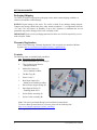
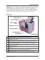
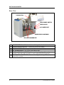
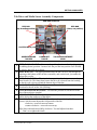
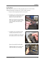
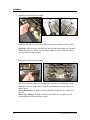
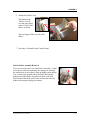
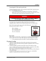
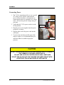
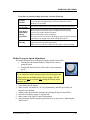
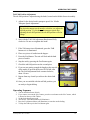
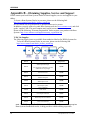
T-350 Dual Tabber OPERATIONS MANUAL Revised: 3-23-09 Part # M-3435 RENA SYSTEMS INC. 136 Green Tree Road STE 140 Oaks, PA 19456-1069 Phone: (610) 650-9170 Fax: (610) 650-9171 E-Mail: [email protected] Web Site: www.renausa.com RENA Systems Inc. would like to Thank You for investing in our quality built products. Please record the following information for future reference: Model: Serial Number: Purchase Date: Purchased From: Dealer Name: Contact Name: Address: Address: Phone Number: Please take this opportunity to register your product. Use the following “Warranty Registration” link to register your product with Rena Systems. http://www.renausa.com/support/warranty_registration.asp 2 T-350 Operations Rev. 3/23/2009 TABLE OF CONTENTS Table of Contents Section Page # SECTION 1 – GETTING ACQUAINTED ________________________________________________ 5 SAFETY PRECAUTIONS _______________________________________________________________ 5 PACKAGING/SHIPPING _______________________________________________________________ 6 WARRANTY REGISTRATION ___________________________________________________________ 6 CONTENTS _________________________________________________________________________ 6 FRONT VIEW _______________________________________________________________________ 7 REAR VIEW ________________________________________________________________________ 8 TAB DRIVE AND MEDIA SENSOR ASSEMBLY COMPONENTS __________________________________ 9 CONTROL PANEL __________________________________________________________________ 10 SECTION 2 – ASSEMBLY ___________________________________________________________ 11 STAND-ALONE MODE _______________________________________________________________ 11 IN-LINE MODE ____________________________________________________________________ 13 In-Line Roller Assembly Removal ____________________________________________________ 15 External Feeder Control Setup ______________________________________________________ 16 CHOOSING A LOCATION _____________________________________________________________ 17 CONNECTING POWER _______________________________________________________________ 18 SECTION 3 – OPERATING THE TABBER _____________________________________________ 19 THEORY OF OPERATION: ____________________________________________________________ 19 Important Operating Tips:__________________________________________________________ 19 LOADING/THREADING TABS: _________________________________________________________ 20 Tab Stock Threading Diagram (Peel Bar Up)___________________________________________ 24 Tab Stock Threading Diagram (Peel Bar Down) ________________________________________ 25 Sheet Separation Adjustment ________________________________________________________ 26 Media Side Guide Adjustment _______________________________________________________ 27 Rear Paper Support Adjustment _____________________________________________________ 27 Loading Media___________________________________________________________________ 28 MEDIA TRANSPORT TEST (PAPER FEED)________________________________________________ 28 MEDIA TRANSPORT SPEED ADJUSTMENT _______________________________________________ 29 ADJUSTING THE TAB POSITION _______________________________________________________ 30 Horizontal Tab Positioning _________________________________________________________ 30 Tab Fold Position Adjustment _______________________________________________________ 31 OPERATING SEQUENCE _____________________________________________________________ 31 SECTION 4 – TROUBLESHOOTING __________________________________________________ 33 TABBING PROBLEMS: _______________________________________________________________ 33 MEDIA FEEDING PROBLEMS: _________________________________________________________ 34 GENERAL PROBLEMS: ______________________________________________________________ 34 SECTION 5 – MAINTENANCE _______________________________________________________ 36 CLEANING ________________________________________________________________________ 36 Tabber Body ____________________________________________________________________ 36 Feed Rollers and Forwarding Rollers_________________________________________________ 37 Media Sensor ____________________________________________________________________ 37 APPENDIX - SPECIFICATIONS ______________________________________________________ 39 APPENDIX B – OBTAINING SUPPLIES, SERVICE AND SUPPORT_______________________ 40 INDEX ____________________________________________________________________________ 42 T-350 Operations Rev. 3/23/2009 3 TABLE OF CONTENTS NOTES _______________________________________________________________________ _______________________________________________________________________ _______________________________________________________________________ _______________________________________________________________________ _______________________________________________________________________ _______________________________________________________________________ _______________________________________________________________________ _______________________________________________________________________ _______________________________________________________________________ _______________________________________________________________________ _______________________________________________________________________ _______________________________________________________________________ _______________________________________________________________________ _______________________________________________________________________ _______________________________________________________________________ _______________________________________________________________________ _______________________________________________________________________ _______________________________________________________________________ _______________________________________________________________________ _______________________________________________________________________ 4 T-350 Operations Rev. 3/23/2009 GETTING ACQUAINTED Section 1 – Getting Acquainted Safety Precautions THIS EQUIPMENT PRESENTS NO PROBLEM WHEN USED PROPERLY. OBSERVE THE FOLLOWING SAFETY RULES WHEN OPERATING THE RENA T-350 TABBER. BEFORE USING THE T-350, YOU SHOULD READ THIS MANUAL CAREFULLY AND FOLLOW THE RECOMMENDED PROCEDURES, SAFETY WARNINGS, AND INSTRUCTIONS: 9 Keep hands, hair, and clothing clear of rollers and other moving parts. 9 Avoid touching moving parts or materials while the machine is in use. Before clearing a jam, be sure machine mechanisms come to a stop. 9 Always turn off the machine before making adjustments, cleaning the machine, or performing any maintenance covered in this manual. 9 Use the power cord supplied with the machine and plug it into a properly grounded wall outlet located near the machine and easily accessible. Failure to properly ground the machine can result in sever personal injury and/or fire. 9 The power cord and wall plug is the primary means of disconnecting the machine for the power supply. 9 DO NOT use an adapter plug on the line cord or wall outlet. 9 DO NOT remove the ground pin from the line cord. 9 DO NOT route the power cord over sharp edges or trapped between furniture. 9 Avoid using wall outlets controlled by wall switches, or shared with other equipment. 9 Make sure there is no strain on the power cord caused by jamming between the equipment, walls or furniture. 9 DO NOT remove covers. Covers enclose hazardous parts that should be accessed by a qualified service representative. Report any damage of covers to your service representative. 9 This machine requires periodic maintenance. Contact your authorized service representative for required service schedules. 9 To prevent overheating, do not cover the vent openings. 9 Use this equipment only for its intended purpose. In addition, follow any specific occupational safety and health standards for your workplace or area. This manual is intended solely for the use and information of Rena Systems Inc., its designated agents, customers, and their employees. The information in this guide was obtained from several different sources that are deemed reliable by all industry standards. To the best of our knowledge, that information is accurate in all respects. However, neither Rena Systems Inc. nor any of its agents or employees shall be responsible for any inaccuracies contained herein. RENA Systems Inc. and “The Envelope Imaging Company” are registered trademarks of Rena Systems Inc. All other trademarks are the property of their respective holders. All rights reserved. No part of this manual may be reproduced or transmitted in any form or by any means, electronic or mechanical, including photocopying, recording, or any information storage and retrieval system, without permission in writing from Rena Systems Inc. T-350 Operations Rev. 3/23/2009 5 GETTING ACQUAINTED Packaging/Shipping The Tabber is shipped in appropriate packaging so that, under normal shipping conditions, it reaches its destination without damage. NOTICE: Report damage to the carrier. The carrier is liable for any damage during transport. Transport and storage should take place under normal conditions, i.e. at temperatures between +5°C and +70°C and relative air humidity of up to 80%. Exposure to conditions that are not permissible may lead to damage which is not externally visible. IMPORTANT Please save the packaging materials for future use! It will be required if you ever need to ship the Tabber. Warranty Registration Please use the following “Warranty Registration” link to register your product with Rena Systems. http://www.renausa.com/support/warranty_registration.asp Contents The following items are included with your tabber: Qty Description (Image Reference) 1 Operations Manual (you’re reading it) 2 Take-Up Spools (not shown) - installed on tabber 2 Media Side Guides (A) - screws attached to tabber 1 Tab Box Tray (B) 1 Power Cord (C) 1 Rear Paper Support (D) - thumb screws attached to tabber 1 Narrow Paper Support Wedge (E) 1 Paper Support Wedge (F) - including thumb screw 1 In-Line Roller Assembly (G) 1 In-Line Guide Assembly (H) A B D E G C F H Note: Tabs can be purchased through your local Rena Systems Dealer. To locate a Rena Systems Dealer in your area, please use the following link. http://www.renausa.com/dealer_locator_search.asp See “Appendix B” for Tab Selection. 6 T-350 Operations Rev. 3/23/2009 GETTING ACQUAINTED Introduction: The T-350 Tabber is a tabletop tabbing machine that is designed for the moderate volume user. It can be used “stand-alone” or “in-line” with other devices. The T-350 Tabber applies Rena FanFold, “tractor-fed” clear, translucent, and paper tab stocks; which have been engineered to run on the T-350. Tab stock can be purchased through your local Rena Systems Dealer. See “Appendix B” for tab selection. Front View TAKE-UP SPOOLS MEDIA SIDE GUIDES FEEDER CONTROL PORT PAPER SUPPORT WEDGE REAR PAPER SUPPORT SHEET SEPARATORS FEED ROLLERS CONTROL PANEL 1. TAKE-UP SPOOLS – Winds up the tab web material (waste). 2. MEDIA SIDE GUIDES – Used to position the media in the tabber and provide 3. 4. 5. 6. 7. 8. straight feeding of media. FEEDER CONTROL PORT– Can be used to control the start/stop function of optional external feeders. Feeder must accept “dry contact” input control. PAPER SUPPORT WEDGE – Allows for adjustments in stack angle, based on media type and length. Helps to force the media against the separation area. REAR PAPER SUPPORT – Provides the proper angle to enhance media feeding and separation. SHEET SEPARATORS (four) – Used to separate a single piece of media from the stack. FEED ROLLERS (four) – Delivers the bottom piece of media, from the stack, through the separation area, and under the forwarding rollers. CONTROL PANEL – Items used to control the operation of the tabber. T-350 Operations Rev. 3/23/2009 7 GETTING ACQUAINTED Rear View TAB BOX TRAY MAIN POWER SWITCH FUSE HOLDER AC POWER INLET PAPER SENSOR ASSEMBLY TAB DRIVE ASSEMBLIES TAB BOX TRAY – Holds the tab box and also guides the tab web into the unit. MAIN POWER SWITCH – Controls the power to the tabber. FUSE HOLDER – The main power fuse (line fuse) is located here. AC POWER INLET– AC power cord connects here. MEDIA SENSOR ASSEMBLY– Detects the leading edge of the mail piece (media). The knob on this assembly is used to adjust the tab fold position. 6. TAB DRIVE ASSEMBLIES– Contains the tab guide chute, peel bar, and tractor drive system. 1. 2. 3. 4. 5. 8 T-350 Operations Rev. 3/23/2009 GETTING ACQUAINTED Tab Drive and Media Sensor Assembly Components PEEL BAR LOCATOR PEEL BAR (down, run position) PEEL BAR (up, threading position) LOCATOR DOTS (red) UPPER PRESSURE ROLLERS LOWER EXIT ROLLER TAB FOLD ADJUSTMENT KNOB 1. PEEL BAR LOCATOR – Use to set the peel bar location to the threading (up) 2. 3. 4. 5. 6. 7. or tabbing (down) position. Locators lock the peel bar into position. Pull forward to release, then slide up or down. PEEL BAR (UP) – The upper position allows the tab web to be fed through the opening at the bottom of the tab drive assembly, and out the back; just under the tractor drive roller. PEEL BAR (DOWN) – When in the lower position, this device creates a sharp bend in tab web. This sharp bend causes the tab to be released from the backing as the tab web is driven around the bottom edge of this bar. LOCATOR DOTS (RED) – Alignment marks used to locate the correct starting location for the tab on the web (backing). UPPER PRESSURE ROLLERS – Provides the pressure to seal the tab to the top of the mail piece (media). LOWER EXIT ROLLER –Seal the tab to the bottom of the mail piece (media) while driving the media out of the tabber. TAB FOLD ADJUSTMENT KNOB – Adjusts the position/angle of the paper sensor, which in-turn adjusts the fold position of the tab. clockwise = more tab area on bottom counter-clockwise = more tab area on top Tip: Start with knob turned fully clockwise. Test and adjust from there. Don’t over-tighten this knob. T-350 Operations Rev. 3/23/2009 9 GETTING ACQUAINTED Control Panel 1. BATCH COUNTER – Counts tab cycles. The counter can be reset to zero, by 2. 3. 4. 5. 10 pressing the small button on this device. Note: The Batch counter will not count items fed in the “paper feed mode”. It only counts when the unit is in the “tab mode” (tab button illuminated). SPEED CONTROL DIAL – Controls the media transport speed of the tabber. Clockwise = faster. Counter-clockwise = slower. Important: If you change the transport speed, the tab fold position will also change. Please adjust for the desired transport speed before you adjust for the desired tab fold position. FEED BUTTON – Used to stop/start tabber transport. This button illuminates when the feed system has been activated. POWER LED– Illumination indicates that the tabber’s Main Power Switch is on, and the unit is receiving power. TAB BUTTON– Used to turn the tab function on/off. OFF = Tab Mode Off (Will feed paper without applying tabs.) ON (illuminated) = Tab Mode Activated T-350 Operations Rev. 3/23/2009 ASSEMBLY Section 2 – Assembly Stand-Alone Mode Note: This process assumes you will be using the system as a “stand-alone” tabber. Follow the steps below to prepare the T-350 for “stand-alone” operation. 1. Remove all the components from the accessory box. 2. Attach the Rear Paper Support using the two thumbscrews and washers provided. The finger, on the bottom edge of the Paper Support, must be inserted into one of the locator holes, in the frame of the tabber. The Paper Support is then secured to the frame with the thumbscrews, as shown. When double tabbing; set the Paper Support to the far left locator hole. This will center the Paper Support on the tabber. When single tabbing the Paper Support can be positioned in any of the other locator holes. Try to position the Paper Support so it is center on the media you are feeding. 3. Install the Paper Support Wedge onto the Rear Paper Support, using the thumb screw and washer supplied. Two Paper Support Wedges are included with the tabber. The narrow wedge is for media that is 6.25” wide or less. The standard (wider) wedge is for all other media. T-350 Operations Rev. 3/23/2009 11 ASSEMBLY 4. Attach both Media Side Guides to the unit as shown. The bottom of the media side guide fits into the brass bushing, on the shaft, as shown. The guides are secured to the mounting blocks using the two Philips head screws, supplied. 5. Attach the Tab Box Tray. The hooks on the Tab Box Tray fit over the upper shaft, at the exit end of the tabber, as shown. The tray hangs off the exit end of the tabber. 6. Proceed to “Choosing a Location”. 12 T-350 Operations Rev. 3/23/2009 ASSEMBLY In-Line Mode Note: This process assumes you will be using the system as an “in-line” tabber. Follow the steps below to prepare the T-350 for "in-line" operation. 1. Remove all the components from the accessory box. 2. If installed; remove the Rear Paper Support from the tabber, by removing the two thumb screws and washers shown. Note: You will need to reuse the thumb screws and washers to install the In-Line Guide Assembly, shown later in this procedure. 3. If installed; remove the Material Guide Assembly from the tabber as shown. Loosen the two thumb screws that secure the assembly to the side wall, as shown. Remove the assembly from the tabber Tighten the thumb screws, into the sidewalls of the tabber, for safe keeping. T-350 Operations Rev. 3/23/2009 13 ASSEMBLY 4. Install the In-Line Roller Assembly. Install the flat end of the shaft first and then insert the pointed end of the shaft. Important! Make sure the shaft ends are inserted under the spring wire (located behind the sidewall). When you insert the pointed end of the shaft, the spring wire will lock the shaft in place. 5. Install the In-Line Guide Assembly. The in-line guide assembly can be attached to a number of mounting locations, along the front wall of the tabber; using the two thumb screws and washers; as shown above. When dual tabbing; the guide assembly should be installed so it is centered on the unit. When single tabbing; the guide assembly can be offset to the right, to better accommodate the media feeding location. 14 T-350 Operations Rev. 3/23/2009 ASSEMBLY 6. Attach the Tab Box Tray. The hooks on the Tab Box Tray fit over the upper shaft, at the exit end of the tabber, as shown. The tray hangs off the exit end of the tabber. 7. Proceed to “External Feeder Control Setup”. In-Line Roller Assembly Removal If you ever need to remove In-Line Roller Assembly, a small screw driver can be inserted under the spring wire, through the smaller hole in the sidewall. Push up lightly on the spring wire, to release the pointed end of the shaft; allowing the pointed end of the shaft to be pulled out of the side-wall. The flat end of the shaft can be removed from the sidewall, without releasing the spring wire tension. T-350 Operations Rev. 3/23/2009 15 ASSEMBLY External Feeder Control Setup CAUTION THIS PROCESS SHOULD BE PERFORMED BY A QUALIFIED SERVICE PERSON. PLEASE CONTACT YOUR LOCAL RENA SYSTEMS DEALER FOR TECHNICAL HELP. THE INFORMATION PROVIDED IN THIS SECTION IS FOR USE BY THE TECHNICIAN. WARNING BEFORE PERFORMING THIS TASK, DISCONNECT THE TABBER FROM ITS POWER SOURCE! Transport Stop Delay Feature: This feature allows the tabber to continue to cycle the transport system for a few seconds, before the tabber transport stops. When used with an external feeder; this feature is useful to clear the tabber of material before it stops. When the Feed button is pressed, to start the system; the tabber transport system is engaged. At the same time the tabber sends a signal to the external feeder, to start the feeder. When the Feed button is pressed again, to stop the system; the tabber sends a signal to stop the feeder, but the tabber transport continues to cycle for a few additional seconds. This process clears the tabber of all media before it stops. To enable the Transport Stop Delay, feature; Jumper J7 must be removed from the Main PCB of the tabber. Keep the jumper in a safe place for possible future use. To disable the Transport Stop Delay feature; Jumper J7 must be installed on the Main PCB of the tabber. J7 Jumper J7 installed = “stand-alone” mode (no delay in tabber transport stop) Jumper J7 removed = “in-line” mode (3 second delay in tabber transport stop) 16 T-350 Operations Rev. 3/23/2009 ASSEMBLY Connecting the T-350 to an External Feeder Using the appropriate interface cable, attach the external feeder’s interface port to the T-350’s FEEDER interface port. T-350 to RENA EasyFeed 120 feeder: Use Cable Part#: 33E-500-192 Note: Cable 33E-500-192 was made for the T-950, but it will work with T-350 as well. Set the switch, on the bottom of the EasyFeed 120, to “N.O.”. WARNING IF AN INNAPPROPRIATE CABLE CONNECTION IS MADE, DAMAGE TO THE TABBER AND OR FEEDER MAY OCCUR. If you don’t have the appropriate cable or don’t know if your feeder is compatible; please contact your local Rena Systems Dealer for technical help. The T-350’s feeder interface port provides the following dry contact outputs. Maximum current capacity = 10 mA Pin 1: Common Pin 2: Normally Closed Pin 3: Normally Open Pin 4: No Connection 1 3 2 Riser Stand: When using an external feeder, an appropriate riser stand must be used under the feeder; to place the feeder output at the appropriate input height for the tabber. T-350 to RENA EasyFeed 120 feeder. Use Riser Stand Part #: RS-100. Choosing a Location The tabber should be placed on a flat, stable work surface that can properly support the weight of the tabber and any peripheral equipment (feeder, conveyor, media, tabs, etc…). The tabber should be located in an area that is away from windows or heat sources. Sunlight will deteriorate the rubber and plastic components on the tabber, and can cause problem with the function of the media sensor. Note: Strong over-head interior lighting can also cause problems with the function of the media sensor. An electrical outlet must be located near the unit. The power cord should be routed in a way that it does not cross an access corridor. T-350 Operations Rev. 3/23/2009 17 ASSEMBLY Connecting Power 1. The T-350 is manufactured for use on a specific AC voltage source. Before connecting the power cord to the tabber; verify that you are connecting the unit to a compatible AC voltage source. See serial tag for the voltage rating of your unit. 2. Verify that the T-350’s power switch is in the off (0) position. Power Switch Power Cord 3. Plug the power cord, supplied, into the power receptacle; as shown. 4. Plug the other end of the power cord into the wall outlet. 5. To protect the unit from possible power line surges or spikes; it is recommended that you attach the tabber to suitable surge/spike protector. Serial Tag CAUTION DO NOT USE AN ADAPTER PLUG OR EXTENSION CORD TO CONNECT THE TABBER TO THE WALL RECEPTACLE. DO NOT USE OUTLETS CONTROLLED BY WALL SWITCHES. DO NOT USE AN OUTLET THAT SHARES THE SAME CIRCUIT WITH LARGE ELECTRICAL MACHINES OR APPLIANCES. 18 T-350 Operations Rev. 3/23/2009 OPERATING THE TABBER Section 3 – Operating the Tabber Theory of operation: The T-350 can be used as a “stand-alone” machine or an “in-line” machine. It can be setup to place one or two tabs at the leading edge of the media. When the media sensor detects the lead edge of the media the tab drive cycle is started. A tab is presented in front of the media. The media contacts the center area of the tab. As the media advances forward, the exit rollers fold and press the tab to the media, as they drive the media out of the exit end of the tabber. The tab drive cycle stops until another piece of media is seen by the media sensor. The tab fold position is adjusted by changing the position of the media sensor, using the “Tab Fold Adjustment Knob”. When the tab fold knob is adjusted fully clockwise, the media sensor sees the leading edge of the media at the earliest time. This provides more time for the tab to advance, before the media makes contact with the tab; thereby providing more tab area to the bottom of the media. The further the tab fold knob is adjusted counter-clockwise, the later the media sensor detects the leading edge of the media. This provides less time for the tab to advance; thereby providing more tab area to the top of the media. Important Operating Tips: Media transport speed will effect the tab fold position. It is important to set your desired media transport speed first, and then adjust for the desired tab fold position. Example: If you slow the machine down, without readjusting the tab fold position, you will notice that more tab area will be applied to the bottom of the media. This occurs because a slower media transport speed allows the tab to advance further before the leading edge of the media makes contact with the tab. If you turn the Tab Fold Adjustment Knob too far counter-clockwise, you can experience erratic tab placement on the media. This occurs because there is not enough tab area/length advancing below the surface of the media. When the leading edge of the media hits the tab, the tab may not fold around the edge, as expected. Instead it may slide across the top of the media and attach at any point along the top of the media, or not attach to the media at all. If you experience erratic tab placement behavior or tabs being dispensed off the media; reset the Tab Fold Adjustment Knob to the fully clockwise position. Then slowly adjust the knob counterclockwise, for the desired tab fold position. Run at least two pieces, each time you make an adjustment, and check the new tab fold position. If you are still experiencing tab positioning problems, even after following the above procedure, check to be sure you have threaded the tabs correctly. See the “Troubleshooting” Section for additional information. T-350 Operations Rev. 3/23/2009 19 OPERATING THE TABBER Loading/Threading Tabs: See the “Tab Stock Threading Diagrams” for additional help. 1. Remove the lid from the box of tab stock. Tip: The box lid can be placed on the bottom of the tab box, for storage. 2. Slide the tab box into the Tab Box Tray, as shown. 3. Thread the tabs over the black plastic shaft and under the narrow metal shaft. Note: If there are two narrow metal shafts on your Tab Box Tray, one right below the other, thread the tab stock between these two shafts. IMPORTANT! Verify Proper Tab Stock Orientation. At this point, the tab side of the stock, should be facing down, as shown above. If the tab side of the stock is facing up, then you must remove the tab box from the tray, turn it around 180 degrees and restart from step 1. 4. Remove the first 18 tabs from the backing, to create a leader. 5. Lift the peel bar to its “threading position”. Tip: The peel bar locks into the upper and lower positions. Pull forward on the peel bar locators, to release the peel bar, and slide the peel bar to the new position. When you release the peel bar locators, the peel bar will lock into the new position. 20 T-350 Operations Rev. 3/23/2009 OPERATING THE TABBER 6. Thread the tabs under the small shaft at the top of the tab drive assembly. Pull about 18 inches of tab stock out the front of the tab drive assembly. Verify Proper Tab Stock Orientation: The tabs must be located on the front side of the stock, as shown. If the tabs are located on the back of the stock, then you must remove the tabs from the unit, remove the tab box from the tray and turn it around 180 degrees. Re-start process from step 1. Shaft 7. Thread the tabs under the peel bar and out the other side of the tab drive assembly, as shown. Note: Red tab stock shown to improve visibility. 8. Position the tab stock so the hole, in center of the first tab, is aligned with the red dots at the inside edges of the tab drive assembly. T-350 Operations Rev. 3/23/2009 21 OPERATING THE TABBER 9. Bring the tab backing up around the back side of the Take-Up Spools and insert the end of the leader into the slit, in the spool. Tip: Creasing the tab backing, at the insert point, will help it hold onto the spool. 10. Advance the Take-Up Spool, until you have removed the slack in the leader. Tip: To prevent the tab backing from slipping off the spool, you need at least one complete wrap of tab backing around the spool. 11. Re-verify that the hole, in center of the first tab on the leader, is still aligned with the red dots at the inside edges of the tab drive assembly. IMPORTANT! When the peel bar is in its upper position (threading position); the red dots, at the inside edges of the tab drive assembly, should align with the hole in the center of the first tab. Verify that this alignment is correct, before you continue. 22 T-350 Operations Rev. 3/23/2009 OPERATING THE TABBER 12. Using the peel bar locators; side the peel bar down to its “run position”. It should lock into position. IMPORTANT! When the peel bar is in the lower position (run position); the red dots, at the inside edges of the tab drive assembly, should align with the space between two tabs. Verify that this alignment is correct, before you continue. 13. If you are only placing one tab onto the media, then you are finished with the tab loading/threading process. If you plan to place two tabs onto the media; then you will need to repeat this process, beginning from step 3, in order to load/thread a second row of tab stock into the tabber. See the “Tab Stock Threading Diagrams” for additional help. 14. Proceed to “Setting Up the Feed System”. T-350 Operations Rev. 3/23/2009 23 OPERATING THE TABBER Tab Stock Threading Diagram (Peel Bar Up) This is the “threading position” for the peel bar. The peel bar must be in this position before you can attempt to thread the tabber. TAB STOCK TAB BOX TRAY TAKE-UP SPOOL SIDE VIEW TAB DRIVE ASSEMBLY FRONT VIEW TAB STOCK PEEL BAR UP FIRST TAB POSITION Hole in tab aligned with red dots. 24 T-350 Operations Rev. 3/23/2009 OPERATING THE TABBER Tab Stock Threading Diagram (Peel Bar Down) This is the “run position” for the peel bar. The peel bar must be in this position before you attempt to run the tabber. TAB STOCK TAB BOX TRAY TAKE-UP SPOOL SIDE VIEW TAB DRIVE ASSEMBLY FRONT VIEW TAB STOCK PEEL BAR DOWN RUN POSITION Hole between tabs aligned with red dots. T-350 Operations Rev. 3/23/2009 25 OPERATING THE TABBER Setting Up the Feed System Sheet Separation Adjustment This procedure is used to insure that only one piece of media is fed at a time. 1. Move the Media Side Guides so that the sheet separators are accessible. 2. Loosen the locking screw and raise the separator, then tighten the locking screw to hold the separator in the up position. Repeat this step for all separators. 3. Place a single piece of media under the separators. The media should be positioned at the approximate location that you plan to feed the media through the tabber. On the separators that have media beneath them; loosen the separator locking screws, just enough to allow the separators to drop freely against the media. Then tighten the locking screws. IMPORTANT Be sure that unused separators are locked in their raised position. If not, they will rub on the feed rollers, causing transport problems and damage to the rollers and separators. 26 T-350 Operations Rev. 3/23/2009 OPERATING THE TABBER Media Side Guide Adjustment 1. Adjust the Media Side Guides so that they are about a dimes width (~1/32-inch) from the sides of the media. Tighten the locking screws on the side guides to secure their positions. Rear Paper Support Adjustment 1. Verify that the Rear Paper Support has been positioned appropriately, for your application. See Section 2, Step 2, for installation details. For best results, the Rear Paper Support should be centered below the media you are feeding. 2. Verify that the appropriate Paper Support Wedge has been installed; to accommodate your media width. See Section 2, Step 3 for installation details. Narrow Wedge = Media that is 6.25” or less in width. Standard Wedge = Media that is wider than 6.25”. Narrow Wedge Adjustment 3. Place a single mail piece into the feed section (hopper), so that it is touching or starting to feed under the sheet separators. 4. Place a second mail piece on top of the first piece, so it is also touching the sheet separators. 5. Standard Wedge Adjustment Loosen the thumb screw that secures the Paper Support Wedge to the Rear Paper Support. Position the Paper Support Wedge so the trailing edge of the second piece of media is aligned with the curve in the wedge, as shown. T-350 Operations Rev. 3/23/2009 27 OPERATING THE TABBER Loading Media When placing media into the tabber, it is important to follow these steps. 1. Start by placing a single mail piece into the feed section, so that it is touching or starting to feed under the sheet separators. 2. Fan the stack of material so the bottom pieces are closest to the separation point, as shown. Then carefully place the stack into the hopper. 3. Additional pieces can be placed onto the stack, as described in the above step. 4. If the tabber runs out of material, be sure to reload the tabber beginning with the first step. Media Transport Test (Paper Feed) Take the time to verify proper media transport before trying to tab. If the media doesn’t feed correctly, it will not be tabbed correctly. Proper Media Transport: One piece of media is fed at a time. A gap of at least 1 inch is generated between each piece of media. Media is feeding straight. 1. Start by placing one piece of media into the hopper, so it is against or just feeding under the separators. 2. Place a handful of media on top of the piece already in the hopper. NOTE: When placing material into the hopper, ensure that it is fanned so the bottom pieces stick out further than the top pieces. See “Loading Media”. 3. Make sure the Tab button is “off” (not illuminated), and then press the Feed button to start feeding. 28 T-350 Operations Rev. 3/23/2009 OPERATING THE TABBER If you have a problem feeding the media, check the following: Feeding Doubles Reduce the distance between the separator fingers and the feed roller. Try setting the separation using one sheet less than the overall thickness of your media. Hesitating or Not Feeding Increase the distance between the Media Side Guides and the media. Top Sheet is Pulled Back During Separation Skewing -Reset the sheet separation using a slightly thicker adjustment. When setting the separators; place an additional sheet of paper between your media and the separators. -Don’t let the hopper empty completely. The last few pieces of media, in the hopper, may not separate properly when there is no weight above them to hold them closed. -Place the Media Side Guides closer to the edges of the media. -Check/adjust the separation adjustment. -Make sure the media was loaded into the hopper correctly/straight. Media Transport Speed Adjustment The media transport speed is adjusted using the Speed Control Dial. Turning the dial counterclockwise will provide a slower transport speed. Turning the dial clockwise will provide a faster transport speed. IMPORTANT If you change the media transport speed after adjusting the tab fold position, the tab fold position will also change. The tab fold position must be adjusted after setting the desired media transport speed. 1. Load media into the hopper. 2. Make sure the Tab button is “off” (not illuminated), and then press the Feed button to start feeding. 3. Adjust for the desired media transport speed using the Speed Control Dial. 4. Press the Feed button again, to stop the unit. 5. Make a note of the Speed Control Dial position. 6. Once the desired media transport speed has been set; proceed to “Adjusting the Tab Position”. T-350 Operations Rev. 3/23/2009 29 OPERATING THE TABBER Adjusting the Tab Position Horizontal Tab Positioning The desired horizontal tab position is obtained by sliding the Tab Drive Assemblies to the desired position. 1. If the TAB button is illuminated; turn it off by pressing the TAB button. 2. Set the speed control dial to minimum. Feed a single piece of media into the tabber and stop it as it is just starting to travel under the exit rollers, as shown. This can be accomplished by pressing the FEED button to start feeding the media, then quickly pressing the FEED button again to stop feeding the media. It may take a few tries to get a piece of media to stop as it just starts to exit the tabber. 3. Slide the Tab Drive Assemblies to the desired tab position. The black roller, located at the bottom of the tab drive assembly, can be used to approximate the location that the tab will be applied to the media. 4. Adjust the positions of the Take-Up Spools so they are aligned above the Tab Drive Assemblies. 30 T-350 Operations Rev. 3/23/2009 OPERATING THE TABBER Tab Fold Position Adjustment The tab fold position is adjusted using the knob, located on the Media Sensor Assembly. 1. Adjust for the desired media transport speed. See “Media Transport Speed Adjustment”. IMPORTANT The desired transport speed must be set before you adjust the tab fold position. If you change the transport speed after adjusting the tab fold position, the tab fold position will also change. 2. Start with the Tab Fold Adjustment Knob turned fully clockwise. Do not over-tighten this knob! 3. If the Tab button is not illuminated; press the TAB button so it is illuminated. 4. Place two pieces of media into the hopper. 5. Press the Feed button. The unit will feed and tab both pieces of media. 6. Stop the unit by pressing the Feed button again. 7. Check the tab fold position on the second piece. 8. If you are not getting enough tab length on the top side of the media, to provide the desired 50/50 fold; turn the Tab Fold Adjustment Knob counterclockwise, about 1/4 turn. 9. Repeat from step 4 until you achieve the desired tab fold. 10. Once you are satisfied with the tab fold position, you are ready to begin tabbing. Operating Sequence 1. Turn on the Main Power Switch. 2. If you want to zero out the Job Counter; press the reset button on the Job Counter, which is located on the top of the Tabber. 3. Set the desired transport speed. 4. Activate the Tab button (button will illuminate) 5. Press the Feed button (button will illuminate) to start the media feeding. 6. To Stop the Tabber press the Feed button again. T-350 Operations Rev. 3/23/2009 31 OPERATING THE TABBER NOTES _______________________________________________________________________ _______________________________________________________________________ _______________________________________________________________________ _______________________________________________________________________ _______________________________________________________________________ _______________________________________________________________________ _______________________________________________________________________ _______________________________________________________________________ _______________________________________________________________________ _______________________________________________________________________ _______________________________________________________________________ _______________________________________________________________________ _______________________________________________________________________ _______________________________________________________________________ _______________________________________________________________________ _______________________________________________________________________ _______________________________________________________________________ _______________________________________________________________________ _______________________________________________________________________ _______________________________________________________________________ 32 T-350 Operations Rev. 3/23/2009 TROUBLESHOOTING Section 4 – Troubleshooting Tabbing Problems: Problem Tab Fold Placement Inconsistent Too Much Tab is Applied to Top of Media; even when Tab Fold Adjustment Knob is turned fully clockwise. Horizontal Tab Placement Varies or Tabs Not Evenly Applied Multiple Tabs Placed on Single Piece of Media Media Feeds Without Tabbing Tabs are Dispensed When No Media is Feeding Thru Unit. Tab Doesn’t Seal Tight Against Leading Edge of Media. Tab does not stay attached to media Leading Edge of Media is Crushed by Tab T-350 Operations Rev. 3/23/2009 Possible Cause Tab Fold Adjustment Knob may be set too far counter-clockwise. Tabs not threaded correctly. With Peel Bar down; space between tabs should align with red marks on side-walls of Tab Drive Assembly. Rollers dirty, glazed or worn. Media feeding skewed. Tabs not threaded correctly. With Peel Bar down, space between tabs should align with red marks on side-walls of Tab Drive Assembly. Media feeding skewed. Media Side Guides loose. Media Sensor Dirty Dark (non-reflective) area on top side of media. Try flipping media over. Tab function (Tab Button) not turned ON. Out of Tabs. Tabs threaded incorrectly. Tabs must face out; as viewed from exit end of unit. Tabs not peeling off backing. Separation set too light. No gap between pieces. Media Sensor dirty/damaged. Media positioned incorrectly; missing sensor. Fuse F2 on Main PCB is blown. Contact your local Rena Systems Dealer for technical support. Media Sensor and area below sensor may need to be cleaned. See Maintenance Section. Bright light interfering with Media Sensor function. Leading edge of media is not staying tightly closed when it hits tab. Perfed tabs tend to fold slightly off leading edge. Not enough tab wrap around media edge. Consider using a rectangular tab (1301 T) Some media surface are not acceptable for self adhesive tab stocks. Tab is too difficult to bend/fold, for the media being used. Try using translucent tabs. Media is too light (flimsy) for crash tabbing. Must use heavier media. 33 TROUBLESHOOTING Media Feeding Problems: Problem Feeding Doubles Media Not Feeding Media Not Feeding Consistently (large gap between pieces) Media Opening as it Feeds Media is Skewing Tabber Transport Stops by Itself (Feed button turns off by itself) Tabber Transport Keeps Running, for a few seconds, after Feed Button is Pressed (off) Possible Cause Media not properly fanned before loading. Nested Media. Reduce the distance between the separator fingers and the feed roller. Separator Fingers worn. Media not properly fanned before loading. Side Guides too tight. Check/Adjust Rear Paper Support. Increase the distance between the separator fingers and the feed roller. Glazed, dirty or worn feed rollers. Too much friction at separation point. Set sheet separators using 1-1/2 times the material thickness. This can happen with last few pieces in hopper, because there is no weight to keep piece closed. Media Side Guides too loose. Separators not set evenly. Separator Fingers or Feed Rollers worn. Out of Paper Condition. The tabber transport will automatically stop after 18 seconds, if the media sensor does not detect media. Media positioned incorrectly; missing Media Sensor. Adjust the media feed position (side guides) so the media will pass under the sensor. Tabber set for in-line operation. Jumper removed from J7 position on board. See details under In-Line Setup. General Problems: Tabber Not Operating Power LED not illuminated Not Advancing Tabs Power LED illuminated 34 Tabber not plugged in. No AC voltage from wall outlet. Main Power Switch not turned on. Line Fuse blown. Unplug power cord and check/replace fuse. Use properly rated fuse! Fuse F1 on Main PCB blown. Contact your local Rena Systems Dealer for technical support. Tab function (Tab Button) not turned ON. Media Sensor dirty/damaged. Media positioned incorrectly; missing sensor. Fuse F2 on Main PCB is blown. Contact your local Rena Systems Dealer for technical support. T-350 Operations Rev. 3/23/2009 TROUBLESHOOTING NOTES _______________________________________________________________________ _______________________________________________________________________ _______________________________________________________________________ _______________________________________________________________________ _______________________________________________________________________ _______________________________________________________________________ _______________________________________________________________________ _______________________________________________________________________ _______________________________________________________________________ _______________________________________________________________________ _______________________________________________________________________ _______________________________________________________________________ _______________________________________________________________________ _______________________________________________________________________ _______________________________________________________________________ _______________________________________________________________________ _______________________________________________________________________ _______________________________________________________________________ _______________________________________________________________________ _______________________________________________________________________ T-350 Operations Rev. 3/23/2009 35 MAINTENANCE Section 5 – Maintenance This section describes maintenance that an experienced operator can perform. If service or maintenance is needed, beyond what is described in this document, please contact your local Rena Systems Dealer to obtain service and support for your tabber. Service should only be performed by a qualified Rena service person. To locate a Rena Systems Dealer in your area, please use the following link. http://www.renausa.com/dealer_locator_search.asp Cleaning WARNING BEFORE PERFORMING ANY MAINTENANCE, DISCONNECT THE TABBER FROM ITS POWER SOURCE! In order to help maintain proper function; the tabber must be cleaned regularly. Unplug the tabber from the wall outlet before cleaning... The frequency of cleaning will depend on the amount and type of media being run through the tabber. A tabber that is used less frequently may only need to be cleaned once a week. A tabber that is being used heavily, or being used with media that contains a lot of dust or ink residue, may need to be cleaned more than once a day. The visible areas are best cleaned with a vacuum that has a soft brush attachment to help loosen the dust particles. Tabber Body The covers of the machine may be cleaned with any standard household cleaner, which is non-abrasive and does not contain plastic harming solvents. CAUTION NEVER SPRAY OR POUR CLEANERS DIRECTLY ON OR INTO THE TABBER. EXCESS LIQUID COULD HARM ELECTRONIC PARTS. ALWAYS DAMPEN A RAG WITH THE CLEANER AND APPLY IT TO THE PARTS TO BE CLEANED. 36 T-350 Operations Rev. 3/23/2009 MAINTENANCE Feed Rollers and Forwarding Rollers WARNING DO NOT USE SOLVENTS TO CLEAN THE RUBBER ROLLERS The feed and forwarding rollers can become glazed with paper lint and ink from the media. They should be regularly cleaned with a mild household cleaner on a damp cloth. Avoid using solvents on the rubber rollers. Media Sensor WARNING DO NOT USE ABRASIVES OF ANY KIND TO CLEAN SENSORS. DO NOT USE LIQUIDS OF ANY KIND, TO CLEAN SENSORS. Periodically check the media sensor, and the area below the media sensor assembly. The sensor should be clean and free of accumulated paper dust. Use a vacuum with a soft brush attachment or dry compressed air to remove the dust. Direct sunlight and strong over-head lighting may negatively affect the function of the media sensor. If you are experiencing tabbing problems, relocate the unit to an area that is not as bright. T-350 Operations Rev. 3/23/2009 37 MAINTENANCE NOTES _______________________________________________________________________ _______________________________________________________________________ _______________________________________________________________________ _______________________________________________________________________ _______________________________________________________________________ _______________________________________________________________________ _______________________________________________________________________ _______________________________________________________________________ _______________________________________________________________________ _______________________________________________________________________ _______________________________________________________________________ _______________________________________________________________________ _______________________________________________________________________ _______________________________________________________________________ _______________________________________________________________________ _______________________________________________________________________ _______________________________________________________________________ _______________________________________________________________________ _______________________________________________________________________ _______________________________________________________________________ 38 T-350 Operations Rev. 3/23/2009 APPENDIX Appendix - Specifications T-350 Dual Tabber Dimensions: 10.5" W x 19" D x 15" H Speed: Up to 18,000 pieces per hour (8.5" tri-folded mailer) Weight: 40 lbs Media Size: Minimum (L x W): 3.5" x 5.5" Maximum (L x W): 9” x 12” Media Thickness: Up to 1/8” Tab Size: 13/16" x 13"/16" to 13/16" x 15/16" Tab Materials Clear, Translucent, or Paper Tab Tray Capacity: 5,000/sleeve; 30,000/box Counter: 5-digit LCD (operator resettable) Feeder: Built-in Bottom Fed Friction Feed (Hopper Removes To Run In-Line) Feeder Capacity: Up to 300 Tri-Folded Mailers Electrical: 110VAC 60Hz or 220VAC 50Hz | 1A Options: RENA Fanfold Tabs, Conveyor/Stacker/Dryer, Drop Tray Specifications subject to change without notice. T-350 Operations Rev. 3/23/2009 39 APPENDIX Appendix B – Obtaining Supplies, Service and Support Please contact your local Rena Systems Dealer to obtain supplies, service and support for your tabber. To locate a Rena Systems Dealer in your area, please use the following link. http://www.renausa.com/dealer_locator_search.asp Service should only be performed by a qualified Rena service person. In addition, you may wish to log onto Rena Systems web site (www.renausa.com), and click on the “support” link. This area contains many useful resources. Please use the following “Warranty Registration” link to register your product with Rena Systems. http://www.renausa.com/support/warranty_registration.asp T-350 Tab Supplies The following supply items are available from authorized dealers for RENA Systems Inc. To locate a Rena Systems Dealer in your area, please use the following link. http://www.renausa.com/dealer_locator_search.asp Part # Description Qty per box 13/16” W x 15/16” H White Paper Rectangle 1301 T Use with thicker materials to provide additional tab wrap length. 30, 000 1402 T 13/16” Diameter Translucent Circle 30, 000 1403 T 13/16” W x 13/16” H Translucent Square 30, 000 1700 T 13/16” Diameter White Paper Circle 30, 000 1701 T 13/16” W x 13/16” H White Paper Square 30, 000 1702 T 13/16” Diameter Clear Circle 30, 000 1704 T 13/16” W x 13/16” H Clear Square with Perf 30,000 1705 T 13/16” Diameter White Paper Circle with Perf. 30, 000 1706 T 13/16” Diameter Clear Circle with Perf 30, 000 Note: The T-350 requires FanFold, “tractor-fed”, tab stocks. Please use the appropriate Rena Systems branded tab stocks, to help provide a reliable tabbing experience. 40 T-350 Operations Rev. 3/23/2009 APPENDIX NOTES _______________________________________________________________________ _______________________________________________________________________ _______________________________________________________________________ _______________________________________________________________________ _______________________________________________________________________ _______________________________________________________________________ _______________________________________________________________________ _______________________________________________________________________ _______________________________________________________________________ _______________________________________________________________________ _______________________________________________________________________ _______________________________________________________________________ _______________________________________________________________________ _______________________________________________________________________ _______________________________________________________________________ _______________________________________________________________________ _______________________________________________________________________ _______________________________________________________________________ _______________________________________________________________________ _______________________________________________________________________ 41 T-350 Operations Rev. 3/23/2009 INDEX INDEX A M AC Power Inlet · 8 Assembly · 11 Main Power Switch · 8 Maintenance · 36 Media Sensor Assembly · 8, 9 Media Side Guide Adjustment · 27 Media Side Guides · 6, 7 Media Transport Speed Adjustment · 29 Media Transport Test · 28 B Batch Counter · 10 C Choosing a Location · 17 Cleaning · 36 Connecting Power · 18 Contents · 6 Control Panel · 7, 10 E External Feeder Control · 16 F Feed Button · 10 Feed Rollers · 7 Feed System Setup · 26 Feeder Control Port · 7 Front View · 7 Fuse Holder · 8 I In-Line Guide Assembly · 6 In-Line Mode · 13 In-Line Roller Assembly · 6 L Loading Media · 28 Loading/Threading Tabs · 20 Locator Dots (red) · 9 Lower Exit Roller · 9 42 O Operating Sequence · 31 Operating the Tabber · 19 P Packaging/Shipping · 6 Paper Feed Test · 28 Paper Support Wedge · 6, 7 Paper Support Wedge - Narrow · 6 Peel Bar (down) · 9 Peel Bar (up) · 9 Peel Bar Locator · 9 Power Cord · 6 Power Led · 10 R Rear Paper Support · 6, 7 Rear Paper Support Adjustment · 27 Rear View · 8 Removal - In-Line Roller Assembly · 15 Riser Stand · 17 S Safety Precautions · 5 Service and Support · 40 Sheet Separation Adjustment · 26 Sheet Separators · 7 Specifications · 39 Speed Control Dial · 10 Stand-Alone Mode · 11 Supplies · 40 T-350 Operations Rev. 3/23/2009 Transport Stop Delay Feature · 16 Troubleshooting · 33 T Tab Box Tray · 6, 8 Tab Button · 10 Tab Drive Assemblies · 8 Tab Drive Assembly · 9 Tab Fold Adjustment Knob · 9 Tab Fold Position Adjustment · 31 Tab Position Adjustment · 30 Tab Positioning - Horizontal · 30 Take-Up Spools · 7 Threading Diagram · 24 U Upper Pressure Rollers · 9 W Warranty Registration · 2, 6, 40 T-350 Dual Tabber, and TB-390 Conveyor EasyFeed 120 Feeder, RS-100 Riser, T-350 Dual Tabber, and TB-390 Conveyor Copyright © 2009 Rena Systems Inc All rights reserved