1
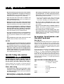
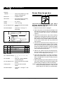
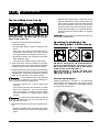
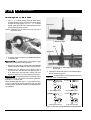
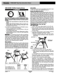
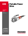
690 Portable Power
Drive
OPERATOR’S
MANUAL
• Français – 11
• Castellano – pág. 23
WARNING!
Read this Operator’s Manual
carefully before using this tool.
Failure to understand and follow the contents of this manual
may result in electrical shock,
fire and/or serious personal
injury
No. 690 Portable Power Drive
Table of Contents
Recording Form for Machine Model and Serial Number ...........................................................................................1
General Safety Information
Work Area Safety........................................................................................................................................................2
Electrical Safety ..........................................................................................................................................................2
Personal Safety...........................................................................................................................................................2
Tool Use and Care......................................................................................................................................................2
Service ........................................................................................................................................................................3
Specific Safety Information
Power Drive Safety .....................................................................................................................................................3
Description, Specifications and Standard Equipment
Description ..................................................................................................................................................................3
Specifications..............................................................................................................................................................3
Standard Equipment ...................................................................................................................................................3
Accessories.................................................................................................................................................................4
Power Drive Inspection.................................................................................................................................................4
Tool And Work Area Set-Up .........................................................................................................................................5
Operating Instructions For Threading with Drop Head Die Heads
Installation of Adapter .................................................................................................................................................5
Threading with 11R Die Head.....................................................................................................................................6
Maintenance Instructions
Motor Brush Replacement ..........................................................................................................................................7
Accessories ...................................................................................................................................................................7
Tool Storage ..................................................................................................................................................................7
Service and Repair ........................................................................................................................................................8
Troubleshooting ............................................................................................................................................................9
Wiring Diagram............................................................................................................................................................10
Lifetime Warranty .........................................................................................................................................Back Cover
ii
Ridge Tool Company
690
Portable Power Drive
690 Portable Power Drive
Record Serial Number below and retain product serial number which is located on nameplate.
Serial
No.
No. 690 Portable Power Drive
General Safety Information
Minimum Wire Gauge for Extension Cord
WARNING! Read and understand all instructions. Failure
to follow all instructions listed below may
result in electric shock, fire, and/or serious
personal injury.
SAVE THESE INSTRUCTIONS!
Work Area Safety
• Keep your work area clean and well lit. Cluttered
benches and dark areas invite accidents.
• Do not operate tools in explosive atmospheres,
such as in the presence of flammable liquids,
gases, or dust. Tools create sparks which may ignite
the dust or fumes.
• Keep by-standers, children, and visitors away
while operating a tool. Distractions can cause you to
lose control.
• Keep floors dry and free of slippery materials
such as oil. Slippery floors invite accidents.
Electrical Safety
• Double insulated tools are equipped with a polarized plug (one blade is wider than the other). This
plug will fit in a polarized outlet only one way. If the
plug does not fit fully in the outlet, reverse the
plug. If it still does not fit, contact a qualified electrician to install a polarized outlet. Do not change
the plug in any way. Double insulation
eliminates
the need for the three wire grounded power cord and
grounded supply system.
• Avoid body contact with grounded surfaces such
as pipes, radiators, ranges and refrigerators. There
is an increased risk of electrical shock if your body is
grounded.
• Do not expose electrical tools to rain or wet conditions. Water entering a tool will increase the risk of
electrical shock.
• Do not abuse cord. Never use the cord to pull the
plug from an outlet. Keep cord away from heat, oil,
sharp edges or moving parts. Replace damaged
cords immediately. Damaged cords increase the
risk of electrical shock.
• When operating a tool outside, use an outdoor
extension cord marked “W-A” or “W”. These cords
are rated for outdoor use and reduce the risk of electrical shock.
• Use proper extension cords. (See Chart) Insufficient
conductor size will cause excessive voltage drop and
loss of power.
2
Nameplate
Amps
0–6
6 – 10
10 – 12
12 – 16
Total Length (in feet)
0 – 25
18 AWG
18 AWG
16 AWG
14 AWG
26 – 50
16 AWG
16 AWG
16 AWG
12 AWG
51 – 100
16 AWG
14 AWG
14 AWG
NOT RECOMMENDED
• Keep all electric connections dry and off the
ground. Do not touch plugs or tool with wet hands.
Reduces the risk of electrical shock.
Personal Safety
• Stay alert, watch what you are doing and use
common sense when operating a power tool. Do
not use tool while tired or under the influence of
drugs, alcohol or medications. A moment of inattention while operating power tools may result in serious personal injury.
• Dress properly. Do not wear loose clothing or
jewelry. Contain long hair. Keep your hair, clothing
and gloves away from moving parts. Loose clothes,
jewelry or long hair can be caught in moving parts.
• Avoid accidental starting. Be sure switch is OFF
before plugging in. Carrying tools with your finger on
the switch or plugging in tools that have the switch ON
invites accidents.
• Remove adjusting keys or wrenches before turning
the tool ON. A wrench or a key that is left attached to
a rotating part of the tool may result in personal injury.
• Do not overreach. Keep proper footing and balance at all times. Proper footing and balance enables
better control of the tool in unexpected situations.
• Use safety equipment. Always wear eye protection.
Dust mask, non-skid safety shoes, hard hat or hearing
protection must be used for appropriate conditions.
Tool Use and Care
• Use clamp or other practical way to secure and
support the workpiece to a stable platform. Holding
the work by hand or against your body is unstable and
may lead to loss of control.
• Do not force tool. Use the correct tool for your
application. The correct tool will do the job better
and safer at the same rate for which it is designed.
• Do not use if switch does not turn the tool ON or
OFF. Any tool that cannot be controlled with the switch
is dangerous and must be repaired.
Ridge Tool Company
No. 690 Portable Power Drive
• Disconnect the plug from the power source before
making any adjustments, changing accessories or
storing the tool. Such preventive safety measures
reduce the risk of starting the tool accidentally.
Drive firmly. If the Power Drive cannot be secured
by a Support Arm, use other mechanical means.
Resists high handle forces developed during use and
prevents losing control of the tool.
• Store idle tools out of the reach of children and
other untrained persons. Tools are dangerous in
the hands of untrained users.
– Only use the aluminum gear case to secure the
power drive. Using the motor housing or handle
may result in damaging or breaking these parts.
• Maintain tools with care. Keep cutting tools sharp
and clean. Properly maintained tools with sharp cutting
edges are less likely to bind and are easier to control.
• Do not use dull or damaged dies. Sharp cutting
tools require less torque and the Power Drive is easier to control.
• Check for misalignment or binding of moving
parts, breakage of parts and any other condition
that may affect the tool’s operation. If damaged,
have the tool serviced before using. Many accidents are caused by poorly maintained tools.
• Do not use this Power Drive if ON/OFF switch is
broken. This switch is a safety device that lets you
shut off the motor by releasing the switch.
• Use only accessories that are recommended for
your tool. Accessories that may be suitable for one
tool may become hazardous when used on another
tool.
• Keep handles dry and clean; free from oil and
grease. Allows for better control of the tool.
Service
• Tool service must be performed only by qualified
repair personnel. Service or maintenance performed
by unqualified repair personnel could result in injury.
• When servicing a tool, use only identical replacement parts. Follow instructions in the Maintenance
Section of this manual. Use of unauthorized parts or
failure to follow maintenance instructions may create a
risk of electrical shock or injury.
Specific Safety Information
WARNING
Read this operator’s manual carefully before using
the 690 Power Drive. Failure to understand and follow the contents of this manual may result in
electrical shock, fire and/or serious personal injury.
Call the Ridge Tool Company, Technical Service
Department at (800) 519-3456 if you have any questions.
Power Drive Safety
• Do not wear gloves or loose clothing when operating Power Drive. Keep sleeves and jackets buttoned. Clothing can be caught, resulting in entanglement and serious injury.
Description, Specifications and
Standard Equipment
Description
The RIDGID Model 690 Power Drive is a double insulated drive which provides power for threading pipe,
conduit, and rod (bolt stock). Forward and Reverse
rotation can be selected with a REV/FOR switch while
ON/OFF is controlled by a paddle switch that cuts off
power when released.
The Power Drive is designed to use RIDGID 11R Drop
Head Die Heads (1/8″ – 2″ pipe). An adapter is required
for the 1/8″ – 11/4″ sizes. The manual 418 Oiling System
is available to flood the work during the threading operations. The No. 691 Support Arm should be used to
secure the Power Drive and resist high handle forces
developed when threading 3/4″ or larger pipe with drop
head die heads.
Specifications/Standard Equipment
Pipe ...............................11R Drop Head Die Heads:
1
/2″ - 2″ (3mm – 50mm)
Motor:
Type ..............................Universal
• The Power Drive is made to turn threaders. Follow
instructions in this Operator’s Manual on proper
use when threading. Other uses may increase the
risk of serious injury.
Volts ..............................115V Single Phase AC,
50-60 HZ
Amps .............................12 amps
Watts .............................1400
• When threading 3/4″ or larger pipe, secure Power
Drive using the No. 691 Support Arm. Hold Power
Ridge Tool Company
3
No. 690 Portable Power Drive
Switches
ON/OFF.......................Heavy Duty Paddle Type with
Safety Locking Device
Power Drive Inspection
WARNING
Directional .....................FOR/REV Switch
Gear Head.....................Die Cast Aluminum Housing,
Permanently Greased
Length ...........................24″ (61cm)
Weight ...........................19 lbs. (8.6 kg)
No. 691 Support Arm.....Absorbs Power Drive Handle
Forces
Die Head Adapter..........Used with 1/8″ through 11/4″
Die Heads
1. Make sure Power Drive is unplugged.
2. Inspect the power cord and plug for damage. If the
plug has been modified or if the cord is damaged, do
not use the Power Drive until the cord has been
replaced.
5″
24″
3. Inspect the Power Drive for any broken, missing,
misaligned or binding parts as well as any other conditions which may affect the safe and normal operation of the tool. If any of these conditions are present,
do not use the Power Drive until any problem has
been repaired.
9″
Figure 1 – 690 Power Drive Dimensions
Catalog Model
No.
No. Description
16708
690
16013
690
16718
690
Weight
lb. kg.
115V Kit less Die Heads
35
w/Case and Support Arm
115V 1/2″ - 2″ NPT
52.5
w/Case and Support Arm
220V, 1/2″ - 2″ NPT w/Support Arm, Export 52.5
15.8
24
24
Accessories
No. 11-R Die Heads (9)...1/8″, 1/4″, 3/8″, 1/2″, 3/4″, 1″, 11/4″,
11/2″, 2″
No. 418 Oiler .................Oiler with 1 Gallon RIDGID
Thread Cutting Oil
No. 691 Support Arm.....Absorbs Power Drive Handle
Forces
Carrying Case .................For Power Drive and Die
Heads
Die Head Adapter ...........Used with 1/8″ through 11/4″ Die
Heads
4
To prevent serious injury, inspect your Power
Drive. The following inspection procedures should
be performed on a daily basis:
4. Use tools and accessories that are designed for your
Power Drive and meet the needs of your application. The correct tools and accessories allow you to do
the job successfully and safely. Accessories suitable
for use with other equipment may be hazardous
when used with this Power Drive.
5. Clean any oil, grease or dirt from all equipment handles and controls. This reduces the risk of injury due
to a tool or control slipping from your grip.
6. Inspect the cutting edges of your dies. If necessary,
have them replaced prior to using the Power Drive.
Dull or damaged dies can lead to binding and poor
quality threads.
7. Clean metal shavings and other debris from the chip
pan of the 418 Oiler. Check the level and quality of the
thread cutting oil. Replace or add oil if necessary.
NOTE! Thread cutting oil lubricates and cools the threads
during the threading operation. A dirty or poor
grade cutting oil can result in poor thread quality.
Ridge Tool Company
No. 690 Portable Power Drive
Tool and Work Area Set-Up
• Depress and hold the switch. Inspect the moving
parts for misalignment, binding, odd noises or any
other unusual conditions that may affect the safe
and normal operation of the tool. If such conditions are present, have the Power Drive serviced.
• Flip the directional switch to the opposite direction.
Check that that Power Drive rotates in an opposite
direction.
WARNING
To prevent serious injury, proper set-up of the
Power Drive and work area is required. The following procedures should be followed to ensure
proper set-up of the tool.
1. Locate a work area that has the following:
• Adequate lighting
• No flammable liquids, vapors or dust that may
ignite.
• Clear path to the electrical outlet that does not
contain any sources of heat or oil, sharp edges or
moving parts that may damage electrical cord.
• Dry place for operator. Do not use the Power Drive
while standing in water.
• Level ground for tristand vise and pipe stands.
2. Clean up the work area prior to setting up any equipment. Always wipe up any oil that may have splashed
or dripped from the oiler to prevent slips and falls.
3. Plug the Power Drive into the electrical outlet making
sure to position the power cord along the clear path
selected earlier. If the power cord does not reach the
outlet, use an extension cord in good condition.
WARNING To avoid electrical shock and electrical
fires, never use an extension cord that is damaged or
does not meet the following requirements:
• The cord is rated as “W” or “W-A” if being used
outdoors.
• The cord has sufficient wire thickness (14 AWG
below 25′/12 AWG 25′ - 50′). If the wire thickness is too small, the cord may overheat, melting
the cord’s insulation or causing nearby objects
to ignite.
CAUTION Change position of the directional switch only
when motor is switched OFF.
Operating Instructions For
Threading with 11-R Die Heads
WARNING
Do not wear gloves or loose clothing when operating
Power Drive. Keep sleeves and jackets buttoned.
Do not use this Power Drive if switches are broken. Always wear eye protection to protect eyes
from dirt and other foreign objects.
When threading pipe 3/4″ or larger, use the No. 691
Support Arm to resist high handle force developed during threading.
Installation of Adapter
Adapter is required for 1/8″ through 11/4″ 11-R Die Heads.
Push Adapter into Power Drive until spring engages
securely (Figure 2). Installation can be made from only
one side of the Power Drive.
WARNING To reduce risk of electrical shock, keep all
electrical connections dry and off the ground. Do not
touch plug with wet hands.
4. Check the Power Drive to insure it is operating properly.
• Depress the paddle switch and safety lock making
sure the Power Drive stops when releasing the
switch.
Figure 2 – Installation of 11-R Die Head Adapter
Ridge Tool Company
5
No. 690 Portable Power Drive
Threading with 11-R Die Head
1. For 11/2″ - 2″ 11-R Die Heads, push die heads, spline
end first, squarely into the Power Drive until the spring
engages securely (Figure 3). For 1/8″ - 11/4″ 11-R Die
Heads, push die heads into adapter spline end first,
until spring engages in notches.
Support Arm
NOTE! Installation can be made from only one side of
the Power Drive.
Figure 4 – Using No. 691 Support Arm When Threading
3
/4″ Pipe and Larger
Pipe
Support Arm
Figure 3 – Installing No. 11-R Die Heads
2. If possible, secure the pipe in a portable tristand vise
or a bench vise.
WARNING To prevent tipping, long lengths of pipe
should also be supported with pipe stand.
3. Be sure the 418 Oiler is properly filled with RIDGID
Thread Cutting Oil. Position the oiler in front of the vise.
4. Position No. 691 Support Arm on pipe so end of
support arm is in line with end of the pipe (Figures 4
& 5). Make sure jaws squarely contact pipe and
tighten handle firmly to prevent slipping of the jaws.
WARNING To avoid serious injury from losing control
of the Power Drive, a support arm should be used when
threading 3/4″ or larger pipe.
Figure 5 – Positioning No. 691 Support Arm In Line with
End of Pipe
5. Position the directional switch for the desired right or
left hand thread (Figure 6).
CAUTION Change position of the directional switch only
when the motor is switched OFF.
CLOCKWISE
When threading pipe less than 3/4″ in size without a support arm, hold onto the Power Drive firmly with one hand
to exert pressure against the handle forces developed during threading.
A. Right Hand Thread ON
COUNTERCLOCKWISE
A. Right Hand Thread OFF
COUNTERCLOCKWISE
B. Left Hand Thread ON
CLOCKWISE
B. Left Hand Thread OFF
Figure 6 – Direction Change Switch/Die Head Orientation
6
Ridge Tool Company
No. 690 Portable Power Drive
6. Place Die Head over end of pipe and insert post of
support arm through hole in gear case.
WARNING For right hand threads, Die Head will rotate
clockwise (looking at the face of the die head). Forces
developed by the threading torque will be in the opposite
(counter-clockwise) direction.
7. Simultaneously actuate the ON/OFF switch and exert
pressure against the Die Head with the palm of free
hand to assist in starting thread. Apply plenty of
thread cutting oil to the dies during threading. This will
reduce the torque required to thread and improve
the thread quality (Figure 7).
8. Keep ON/OFF switch depressed until end of the pipe
is even with edge of the dies. Release the switch
button.
Support Arm Post Passes
Through Gear Case
Maintenance Instructions
WARNING
Make sure machine is unplugged from power
source before performing maintenance or making
any adjustments.
Motor Brush Replacement
Check motor brushes every 6 months and replace brushes when they are worn to less than 1/4″.
Accessories
WARNING Only the following RIDGID products have
been designed to function with the 690 Power Drive.
Other accessories suitable for use with other tools may
become hazardous when used on this Power Drive. To
prevent serious injury, use only the accessories listed
below.
Accessories For Power Drive
Catalog No.
10883
43292
41620
39187
72037
Description
418 Oiler with 1 Gallon of NU-Clear Thread Cutting Oil
691 Support Arm
Gearhead Motor Grease
Adapter for 11-R
460 Tristand Chain Vise
NOTE! See Ridge Tool catalog for listing of 11-R Die
Heads, Pipe Supports, Vises and Thread Cutting
Oil. No. 11-R Die Heads use 12-R Dies.
Figure 7 – Threading Pipe and Applying Oil
9. Back off the Die Head from the threaded pipe, reversing the directional switch and actuating the ON/OFF
switch.
WARNING
Hold onto the Power Drive handle firmly to
resist handle forces developed while backing off the Die
Head.
10. When dies clear the end of the pipe, grip the handle
on top of the Power Drive and remove the Power
Drive and Die Head from the pipe.
Tool Storage
WARNING Motor-driven equipment must be kept
indoors or well covered in rainy weather. Store the Power
Drive in a locked area that is out of reach of children
and people unfamiliar with power drives. This power tool
can cause serious injury in the hands of untrained users.
11. Remove the support arm from the pipe and the pipe
from the vise.
WARNING To avoid injury, make sure long sections of
pipe are supported at the end farthest away from the
vise prior to removal.
12. Clean up any oil spills or splatter on the ground surrounding the vise and oiler.
Ridge Tool Company
7
No. 690 Portable Power Drive
Service and Repair
WARNING
Service and repair work on this Power Drive must be
performed by qualified repair personnel. Tool should be
taken to a RIDGID Independent Authorized Service Center
or returned to the factory. All repairs made by Ridge service facilities are warranted against defects in material and
workmanship.
WARNING When servicing this Power Drive, only
identical replacement parts should be used. Failure to follow these steps may create a risk of electrical shock or
other serious injury.
If you have any questions regarding the service or repair
of this machine, call or write to:
Ridge Tool Company
Technical Service Department
400 Clark Street
Elyria, Ohio 44035-6001
Tel: (800) 519-3456
E-mail: [email protected]
For name and address of your nearest Independent
Authorized Service Center, contact the Ridge Tool Company at (800) 519-3456 or http://www.ridgid.com
8
Ridge Tool Company
No. 690 Portable Power Drive
Troubleshooting
WARNING: Always unplug power cord before servicing Power Drive.
PROBLEM
Motor does not start
CAUSE
CORRECTION
Power drive unplugged
Plug into power source
Fuse blown
Install new fuse
Brushes do not touch armature
Check brushes, replace if worn
Motor sounds
overloaded
Overload because of dull dies
Replace dies
Bad quality or insufficient thread cutting oil
Use RIDGID thread cutting oil in adequate
quantity
Sparks forming at motor
Bad contact between brushes and brush holder
Tighten the screws, make sure brush is pressed
firmly onto commutator
Brushes do not touch commutator properly
Replace worn brushes
Brushes of different manufacture
Only use RIDGID brushes
Sharp edge on brush
Break edge with sand paper
Dull or broken dies
Replace dies
Machine running in wrong direction
Check setting of the direction switch
Improperly set dies
Reset dies
Dull dies
Replace dies
Dies not assembled in correct sequence
Put dies in correct sequence
Low quality pipe
Make sure only pipe of good quality is used
Bad quality or insufficient thread cutting oil
Use only RIDGID thread cutting oil in adequate
quantity
Support arm feedscrew not tight
Tighten feedscrew
Support arm jaws dirty
Clean with wire brush
Support arm not square on pipe
Make sure sits square on pipe
Burr has occurred at the spline end of the die head
Eliminate burr with file
Die head does not start
threading
Damaged Thread
Support arm turns while
threading
Die heads cannot be
changed properly
Ridge Tool Company
9
No. 690 Portable Power Drive
Wiring Diagram
115 VAC
(220 VAC)
Plug
FOR/REV
Switch
Black
(Blue)
White
(Brown)
ON/OFF Switch
Suppressor
(220V Only)
Blue
Grey
Blue
10
White
Grey
White
Ridge Tool Company