1
700
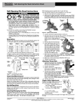
position. See fig. 2d. Actuate paddle switch. When dies clear end of pipe, grip
handle on top of Power Drive and remove Power Drive from pipe.
OPERATING INSTRUCTIONS
IMPORTANT
For your own safety, before assembling and operating
this unit, read this Operator’s Manual carefully and
completely. Learn the operation, applications
and potential hazards peculiar to this unit.
DESCRIPTION AND SPECIFICATIONS
Description
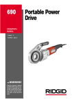
The RIDGID No. 700 Portable Electric Threader is an electric motor driven, heavyduty unit which provides power to thread pipe using RIDGID 12-R drop head die
heads.
MAINTENANCE OF POWER DRIVE
Motor Brush Replacement
Warning: To reduce possibility of electrical shock and accidental starting always
unplug power cord before servicing. Check Motor Brushes every 6 months and
replace Brushes when they are worn to less than 1/4” (6 mm).
The unit is designed to be maintenance free apart from the motor brushes which
will wear. All other maintenance should be performed by factory approved service
stations. Permanent oil filling - no maintenance required.
TROUBLE SHOOTING
Warning
Each remedy with ! has to be repaired by a qualified electrical craftsman.
Disconnect power cord.
Trouble shooting
Possible cause
Remedy
- motor does not start
- interruption of supply
- fuse has been blown
- brushes do not touch armature
- examine the supply !
- install a new fuse
- check the brushes, renew
used brushes
- motor cannot be loaded
- short circuit
- look for the short circuit
!
and resolve
- renew the dies
- use RIDGID thread cutting
oil in adequate quantity
!
SPECIFICATIONS/TECHNICAL INFORMATION
Threading Capacity (Pipe & Conduit): ------------------------------------------ 1/8” - 2”
Gear Head/Type: ------------------------------------------------------------------------ spur
Length: ------------------------------------------------------------------------------ 720 mm
Weight: --------------------------------------------------------------------------------- 14 kg
Motor, Universal Type (115 or 230 V): ------------------------------------------ 1100 W.
Support Arm Model: -------------------------------------------------------------------- 775
Die Head Model: ------------------------------------------------------------------------ 12-R
Standard Equipment
See RIDGID Catalogue
Safety
1. Know your Power Drive. Read the Operator’s Manual carefully. Learn the
operation, application, and limitations as well as the specific potential hazards
peculiar to this tool.
2. Use right tool. We recommend use of 775 Support Arm. The Support Arm
assures safer operation when using the 700 Power Drive horizontally,
vertically or overhead because once it is secured to the pipe to take up the
threading torque, both hands are free to mount the Power Drive into position.
When the job is completed, the Power Drive and Support Arm can be
removed separately assuring safer job take down. Do not force small tool or
attachment to do the job of a heavy-duty tool.
3. Secure work. Use clamp, bench vise or stand vise to hold pipe which is not
otherwise rigidly supported or attached.
Operation
Threading with drop head die heads.
1. 1/8” - 2” RIDGID 12-R Die Heads fit into the RIDGID 700 power threader without
the need for adaptors. Simply push Die Heads spline end first, squarely into
Face Gear until spring catches securely. (See fig. 1).
Check that pawl is fully engaged by rotating diehead by hand.
For right hands threads, installation is as shown in fig. 2a.
For left hand threads, installation is as shown in fig 2b.
Note: The direction change switch is used to back-off the Die Head when the
thread is completed. See fig. 2c.
Important: When threading pipe, the No. 775 Support Arm should be used
and securely locked on the pipe as shown in Figures 3 and 4. To use the
Support Arm and Power Drive together correctly refer to
Figures 3 and 4. Failure to follow these instructions could result in injury to
operator because of torque developed during threading.
2. Place Die Head (already installed in Power Drive) over end of pipe. When using
make sure Power Drive is correctly positioned on Support Arm. For Right Hand
threads, Die Head should rotate CW. (looking at face of Die Head).
Note: During threading, apply plenty of RIDGID Thread Cutting Oil to dies.
3. Simultaneously actuate switch button and exert pressure on machine to make
sure thread is started. Keep switch button depressed until threading is
completed. Releasing switch button will stop the Power Drive.
Caution: Hold onto Power Drive handle firmly to resist initial torque while
backing off Die Head.
4. To back off Die head from threaded pipe, set direction switch to back off
- overload because of dull dies
- bad quality or insufficient thread
cutting oil
- abnormal heating of the motor
- overload because of dull dies
- insufficient cooling air
- renew dies
- clean the air-vent opening
of the motor
- sparks forming at the motor
- dirty commutator
- bad contact between brushes
and brush holder
- please send in for repair !
- tighten the screws, make
sure brush is pressed firmly
onto commutator
- change worn brushes !
(replace only with genuine
RIDGID brushes)
- only use original brushes !
- break edge !
- because of excessive wear
brushes do not touch
commutator properly
- brushes of different manufacture
- sharp edge of brush
- “sparks” in the motor
compartment
- particles come loose from
brushes or armature
(collector) and start glowing
- send machine in for repair
- die head does not start
threading
- dull or broken dies
- machine running in wrong
direction
- change dies
- check setting of the
direction switch
- damaged thread
- dull dies
- dies not assembled in correct
sequence
- low quality pipe
- change dies
- put dies in correct
sequence
- make sure only pipe of
good quality is used
- use only RIDGID thread
cutting oil in adequate
quantity
- bad quality or insufficient
thread cutting oil
- support arm turns while
threading
- support arm jaws dirty
- clean with wire brush
- die heads cannot be changed
properly
- burr has occurred at the spline
end of the die head
- eliminate burr with file
- die head not held tightly
- retaining spring damaged
or worn
- replace retaining spring
!
Fig. 1
Fig. 2a
Fig. 1b
Fig. 2b
Fig. 3
Fig. 2c
Fig. 4
Ridge Tool Subsidiary
Emerson Electric Co.
Cat. N° 000 000 000
700
Portable Power Drive
8
11
13
10
1
2
9
4
3
12
7
24
6
29
51
36
32
37
35
34
5
49
33
28
50
38
27
26
15
16
25
53
54
17
30
18
52
43 44
42
31
41
17
40
48
22
17
45
21
39
17
19
17
20
46
47
23
NOTE: Order parts by Catalog Number only.
DO NOT order by Reference Number.
Ref.
No.
1
2
3
4
Catalog
No.
44785
40770
85920
5
6
46615
42970
7
8
9
10
11
12
13
14
15
16
17
18
19
20
21
22
23
24
25
44060
43395
32475
44915
44910
43345
46775
83890
44900
45315
45060
44830
44820
44825
43335
45165
44555
97260
44055
44075
44565
44430
26
27
Description
E-1893 Tie Bolt (4)
E-1719 Lock Washer (4)
E-10006 Pop Rivet (2)
Name Plate (115V)
Name Plate (230V)
E-833
Torque Arm
B-190-X Gear Case Assembly
(Includes Ref. 7, 13, 14, 52)
D-751
Bearing
C-375-X Face Gear Assembly
E-6085 Spring Pin (2)
E-1967 Spring (2)
E-1966 Adapter Pawl (2)
C-306
Cover
E-897
Screw (8)
E-2870 Lock Nut (8)
E-1960-X 4th Gear Assembly
E-3215 Bearing
E-2630 Bearing (7)
E-1903-X 3rd Gear Assembly
E-1901-X 1st Gear Assembly
E-1902-X 2nd Gear Assembly
C-305-X Fan Housing Assembly
E-2893 Dowel Pin
E-1495 Field Mtg. Screw (2)
E-10649 Switch Button
D-750-X Armature & Fan Assy. (115V)
D-758-X Armature & Fan Assy. (230V)
E-1497 Bearing
E-1340 Retaining Ring
Ref.
No.
28
29
30
31
32
33
34
35
36
37
38
39
40
41
42
43
44
45
46
47
48
49
50
51
52
53
54
55
Catalog
No.
44760
44790
44070
28922
83895
42975
44765
39770
44795
45660
44815
45420
44905
46310
44890
75700
75695
46590
44880
43390
44885
44635
46730
89155
44045
97255
46860
41270
44755
41620
Description
E-1880 Bearing
E-1894 Load Spring
D-755
Field (115V) (Incl. Ref. No. 31)
D-2364 Field (230V) (Incl. Ref. No. 31)
E-1068 Ring Tongue Terminal (2)
B-191-X Motor Housing Assembly
E-1882 Lock Screw
E-3145 Set Screw (2)
E-1895 Brush Holder (2)
E-4404 Brush Cap (2)
E-1900-X Brush Assembly (2)
E-3467 Ground Screw
E-1964 Switch
E-5367 Screw (5)
E-1957 Jumper (2)
E-1953 Lock Ring
E-1961 Lock Washer (Internal Tooth)
E-799
Lock Nut
E-1954 Brush Lead (Blue)
C-370
Switch Insulator
E-1956 Brush Lead (White)
E-1517 Wire Nut
E-889
Cord Retainer
D-1298 Service Cord (115V)
D-747
Service Cord (230V)
Handle
E-912
Grease Fitting
“X” Washer
Insulator Tube
Grease
Ridge Tool Company/Elyria, Ohio, U.S.A.
85
700
Portable Power Drive
No. 700 Power Drive-w/Dual Switch (Europe only)
White
Red
11
Blue
1
Brown
6
4
7
Yellow
18
27
Blue
8
26
2
3
4
5
10
15
13
13
9
12
11
14
16
19
20
17
23
18
25
NOTE: Order parts by Catalog Number only.
DO NOT order by Reference Number.
21
24
Ref.
No.
1
2
3
4
5
6
7
8
9
10
22
Service Note:
For service parts used in early style
machines, refer to the model 700 with
a single control switch.
11
12
13
14
Catalog
No.
32116
32176
32166
32126
32106
30906
44815
30916
39770
18666
32236
32136
32156
66537
32246
32096
Description
Handle
Screw
Clip
Reversing Switch
Switch Liner
Brush Cap
Brush Assembly
Brush Holder
Set Screw (2)
Line Cord (Eur. Di.)
Line Cord 48 Volt
ON/OFF Switch
Screw
Strain Relief (48 Volt)
Strain Relief w/Cable Sleeve
Insulating Cap
Ref.
No.
15
16
17
18
19
20
21
22
23
Catalog
No.
18676
18506
12456
18606
32306
44790
44760
18566
18486
18596
24
25
26
27
32316
44430
44565
18406
63377
Ref.
No.
1
2
3
4
5
6
7
8
9
Catalog
No.
40355
40360
40345
40335
40325
32100
32205
42945
40310
10
11
12
40320
40340
40315
Description
Motor Housing
Sleeve f/Field
Terminal (2)
Field
Field 48 Volts
Load Spring
Bearing
Sleeve f/Screw
Field Mounting Screw (2)
Armature and Fan Assembly
(Eur. Di.)
Armature and Fan Assembly
Retaining Ring
Bearing
Suppressor
Ferrite Bead
No. 775 Support Arm
12
9
10
1
3
4
11
2
5
6
7
8
86
Ridge Tool Company/Elyria, Ohio, U.S.A.
Description
Feed Screw
Jaw Clamp (Incl. Ref. No. 3)
Screw and Washer (2)
Upper Jaw
Hinge Bolt, Washer and Nut
Lower Jaws (1 set) (2 per set)
Lower Jaw Screw (2)
Base
Yoke and Hook Assembly
(Incl. Ref. No. 10)
Hook (Incl. Ref. No. 11)
Hinge Pin
Yoke Assembly Complete
(Incl. Ref. Nos. 1, 2, 4, 5 & 9)