1
PCI-1752U/
PCI-1752USO
64-Channel Isolated Digital
Output PCI Card
User Manual
Copyright
The documentation and the software included with this product are copyrighted 2005 by Advantech Co., Ltd. All rights are reserved. Advantech
Co., Ltd. reserves the right to make improvements in the products
described in this manual at any time without notice. No part of this manual may be reproduced, copied, translated or transmitted in any form or
by any means without the prior written permission of Advantech Co., Ltd.
Information provided in this manual is intended to be accurate and reliable. However, Advantech Co., Ltd. assumes no responsibility for its use,
nor for any infringements of the rights of third parties, which may result
from its use.
Acknowledgements
Intel and Pentium are trademarks of Intel Corporation.
Microsoft Windows and MS-DOS are registered trademarks of
Microsoft Corp.
All other product names or trademarks are properties of their respective
owners.
Part No. 2003175200
1st Edition
Printed in Taiwan
March 2006
PCI-1752 User Manual
ii
Product Warranty (2 years)
Advantech warrants to you, the original purchaser, that each of its products will be free from defects in materials and workmanship for two years
from the date of purchase.
This warranty does not apply to any products which have been repaired or
altered by persons other than repair personnel authorized by Advantech,
or which have been subject to misuse, abuse, accident or improper installation. Advantech assumes no liability under the terms of this warranty as
a consequence of such events.
Because of Advantech’s high quality-control standards and rigorous testing, most of our customers never need to use our repair service. If an
Advantech product is defective, it will be repaired or replaced at no
charge during the warranty period. For out-of-warranty repairs, you will
be billed according to the cost of replacement materials, service time and
freight. Please consult your dealer for more details.
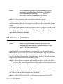
If you think you have a defective product, follow these steps:
1.
Collect all the information about the problem encountered. (For
example, CPU speed, Advantech products used, other hardware
and software used, etc.) Note anything abnormal and list any
onscreen messages you get when the problem occurs.
2.
Call your dealer and describe the problem. Please have your manual, product, and any helpful information readily available.
3.
If your product is diagnosed as defective, obtain an RMA (return
merchandise authorization) number from your dealer. This allows
us to process your return more quickly.
4.
Carefully pack the defective product, a fully-completed Repair and
Replacement Order Card and a photocopy proof of purchase date
(such as your sales receipt) in a shippable container. A product
returned without proof of the purchase date is not eligible for warranty service.
5.
Write the RMA number visibly on the outside of the package and
ship it prepaid to your dealer.
iii
Declaration of Conformity
CE
This product has passed the CE test for environmental specifications
when shielded cables are used for external wiring. We recommend the use
of shielded cables. This kind of cable is available from Advantech. Please
contact your local supplier for ordering information.
CE
This product has passed the CE test for environmental specifications. Test
conditions for passing included the equipment being operated within an
industrial enclosure. In order to protect the product from being damaged
by ESD (Electrostatic Discharge) and EMI leakage, we strongly recommend the use of CE-compliant industrial enclosure products.
FCC Class A
Note: This equipment has been tested and found to comply with the limits
for a Class A digital device, pursuant to part 15 of the FCC Rules. These
limits are designed to provide reasonable protection against harmful
interference when the equipment is operated in a commercial environment. This equipment generates, uses, and can radiate radio frequency
energy and, if not installed and used in accordance with the instruction
manual, may cause harmful interference to radio communications. Operation of this equipment in a residential area is likely to cause harmful interference in which case the user will be required to correct the interference
at his own expense.
FCC Class B
Note: This equipment has been tested and found to comply with the limits
for a Class B digital device, pursuant to part 15 of the FCC Rules. These
limits are designed to provide reasonable protection against harmful
interference in a residential installation. This equipment generates, uses
and can radiate radio frequency energy and, if not installed and used in
accordance with the instructions, may cause harmful interference to radio
communications. However, there is no guarantee that interference will
not occur in a particular installation. If this equipment does cause harmful
interference to radio or television reception, which can be determined by
turning the equipment off and on, the user is encouraged to try to correct
the interference by one or more of the following measures:
PCI-1752 User Manual
iv
• Reorient or relocate the receiving antenna.
• Increase the separation between the equipment and receiver.
• Connect the equipment into an outlet on a circuit different from that to
which the receiver is connected.
• Consult the dealer or an experienced radio/TV technician for help.
FM
The PCI-1752U/PCI-1752USO have passed the FM certification.
According to the National Fire Protection Association, work sites are
classified into different classes, divisions and groups, based on hazard
considerations. PCI-1752U/PCI-1752USO are compliant with the specifications of Class I, Division 2, Groups A, B, C and D indoor hazards.
Technical Support and Assistance
Step 1. Visit the Advantech web site at www.advantech.com/support
where you can find the latest information about the product.
Step 2. Contact your distributor, sales representative, or Advantech's customer service center for technical support if you need additional
assistance. Please have the following information ready before
you call:
- Product name and serial number
- Description of your peripheral attachments
- Description of your software (operating system, version, application software, etc.)
- A complete description of the problem
- The exact wording of any error messages
v
Safety Instructions
1.
Read these safety instructions carefully.
2.
Keep this User's Manual for later reference.
3.
Disconnect this equipment from any AC outlet before cleaning.
Use a damp cloth. Do not use liquid or spray detergents for cleaning.
4.
For plug-in equipment, the power outlet socket must be located
near the equipment and must be easily accessible.
5.
Keep this equipment away from humidity.
6.
Put this equipment on a reliable surface during installation. Dropping it or letting it fall may cause damage.
7.
The openings on the enclosure are for air convection. Protect the
equipment from overheating. DO NOT COVER THE OPENINGS.
8.
Make sure the voltage of the power source is correct before connecting the equipment to the power outlet.
9.
Position the power cord so that people cannot step on it. Do not
place anything over the power cord.
10.
All cautions and warnings on the equipment should be noted.
11.
If the equipment is not used for a long time, disconnect it from the
power source to avoid damage by transient overvoltage.
12.
Never pour any liquid into an opening. This may cause fire or electrical shock.
13.
Never open the equipment. For safety reasons, the equipment
should be opened only by qualified service personnel.
14.
If one of the following situations arises, get the equipment checked
by service personnel:
a. The power cord or plug is damaged.
b. Liquid has penetrated into the equipment.
c. The equipment has been exposed to moisture.
d. The equipment does not work well, or you cannot get it to work
according to the user's manual.
e. The equipment has been dropped and damaged.
f. The equipment has obvious signs of breakage.
15.
DO NOT LEAVE THIS EQUIPMENT IN AN ENVIRONMENT
WHERE THE STORAGE TEMPERATURE MAY GO BELOW -
PCI-1752 User Manual
vi
20° C (-4° F) OR ABOVE 60° C (140° F). THIS COULD DAMAGE THE EQUIPMENT. THE EQUIPMENT SHOULD BE IN A
CONTROLLED ENVIRONMENT.
16.
CAUTION: DANGER OF EXPLOSION IF BATTERY IS
INCORRECTLY REPLACED. REPLACE ONLY WITH THE
SAME OR EQUIVALENT TYPE RECOMMENDED BY THE
MANUFACTURER, DISCARD USED BATTERIES ACCORDING TO THE MANUFACTURER'S INSTRUCTIONS.
The sound pressure level at the operator's position according to IEC 7041:1982 is no more than 70 dB (A).
DISCLAIMER: This set of instructions is given according to IEC 704-1.
Advantech disclaims all responsibility for the accuracy of any statements
contained herein.
Safety Precaution - Static Electricity
Follow these simple precautions to protect yourself from harm and the
products from damage.
1.
To avoid electrical shock, always disconnect the power from your
PC chassis before you work on it. Don't touch any components on
the CPU card or other cards while the PC is on.
2.
Disconnect power before making any configuration changes. The
sudden rush of power as you connect a jumper or install a card may
damage sensitive electronic components.
vii
PCI-1752 User Manual
viii
Contents
Chapter
Chapter
Chapter
Chapter
1 Introduction ..................................................... 2
1.1
Features ............................................................................ 2
1.2
1.3
Installation Guide .............................................................. 5
Accessories........................................................................ 5
Figure 1.1:Installation Flow Chart ................................. 4
2 Installation ....................................................... 8
2.1
2.2
Unpacking ......................................................................... 8
Driver Installation ............................................................. 9
2.3
Hardware Installation ..................................................... 10
2.4
Device Setup & Configuration........................................ 12
2.5
Device Testing................................................................. 13
Figure 2.1: Advantech Automation Software Setup ...... 9
Figure 2.2:Device name listed on Device Manager ..... 12
Figure 2.3:Device Setting dialog box of PCI-1752 ..... 13
Figure 2.4:Advantech Device Manager ....................... 13
Figure 2.5:Digital Output in Device Test dialog box .. 14
3 Signal Connections ........................................ 16
3.1
Location of Jumpers and DIP switch .............................. 16
3.2
I/O Connector Pin Assignment ....................................... 17
3.3
Isolated Digital Output Connections ............................... 20
3.4
Field Wiring Considerations ........................................... 22
Figure 3.1:Location of Jumpers and DIP switch ......... 16
Figure 3.2:I/O Connector Pin Assignments ................. 18
Table 3.1:I/O Connector Signal Descriptions .............. 19
Table 3.2:Power on configuration after hot reset ........ 20
Figure 3.3:Isolated DO: PCI-1752U (sink type) .......... 21
Figure 3.4:Isolated DO: PCI-1752USO (source type) . 21
4 Operation ....................................................... 24
4.1
Board ID.......................................................................... 24
4.2
Channel-Freeze Function ................................................ 25
Table 4.1:Board ID register ......................................... 24
Table 4.2:Board ID setting ........................................... 24
Figure 4.1:Device Number and Board ID .................... 25
Table 4.3:JP2: Channel-Freeze function input mode ... 26
Figure 4.2:Wiring in wet/dry contact input mode ........ 27
Table 4.4:Channel-Freeze function register ................. 27
Table 4.5:Channel-Freeze function bit value ............... 27
Appendix A Specifications ................................................. 30
Table A.1:Isolated Digital Output ............................... 30
Table A.2:General Specifications ................................ 30
Appendix B Block Diagram ............................................... 32
Appendix C Register Structure & Format ....................... 34
ix
Table of Contents
C.1
C.2
C.3
Overview ......................................................................... 34
I/O Port Address Map ..................................................... 34
PCI-1752 Register Format .............................................. 35
Appendix D ADAM-3951/3951B Pin Assignments .......... 38
PCI-1752 User Manual
x
CHAPTER
1
2
Introduction
Sections include:
• Features
• Installation Guide
• Accessories
Chapter 1 Introduction
Thank you for buying the Advantech PCI-1752U/PCI-1752USO isolated
digital output card. The Advantech PCI-1752U/PCI-1752USO isolated
digital output card is a powerful data acquisition card for both 3.3/ 5V
PCI bus. It features a unique circuit design and complete functions for
data acquisition and control. PCI-1752U/PCI-1752USO provides 64 isolated digital output channels. The following sections of this chapter will
provide further information about features of PCI-1752U/PCI-1752USO,
a Quick Start for installation, together with some brief information on
software and accessories.
1.1 Features
The Advantech PCI-1752U/PCI-1752USO DAS cards provide users with
the most requested measurement and control functions as seen below:
PCI-1752 DAS card
64 isolated digital output channels
High-voltage isolation on output channels (2,500 VDC )
Wide output range (5 ~ 40 VDC )
High-sink current for isolated output channels (200 mA max./ch)
Board ID
Output status read-back
Digital output value retained after hot system reset
Channel-Freeze function
The PCI-1752U/PCI-1752USO DAS cards offer the following main features:
Robust Protection
The PCI-1752U/PCI-1752USO features a robust isolation protection for
applications in industrial, lab and machinery automation. The PCI1752U/ USO can durably withstand a voltage up to 2,500 VDC, preventing your host system from any incidental harms.
PCI-1752 User Manual
2
Wide Output Range
The PCI-1752U/PCI-1752USO also features a wide output voltage range
from 5 to 40 VDC, suitable for most industrial applications with 12 VDC /
24 VDC output voltage. In the mean time, we are also ready to serve your
special needs for specific output voltage range. Do not hesitate to ask us
about tailoring our standard products to meet your specifications. All
these merits make PCI-1752U/PCI-1752USO the best choice for industrial applications.
Board ID Setting
The PCI-1752U/PCI-1752USO has a built-in DIP switch that helps
define each card’s ID when multiple cards have been installed on the
same PC chassis. The board ID setting function is very useful when users
build their system with multiple PCI-1752U/PCI-1752USO cards. With
correct Board ID settings, you can easily identify and access each card
during hardware configuration and software programming.
Channel-Freeze Function
The PCI-1752U/PCI-1752USO provides Channel-Freeze function, which
can be enabled either in dry contact or wet contact mode (selectable by
the on-board jumper). When the Channel-Freeze function is enabled, the
last status of each digital output channel will be safely kept for emergency use. Moreover, you can enable this function through software as it
is useful in software simulation and testing program.
Reset Protection
When the system has undergone a hot reset (i.e. without turning off the
system power), the PCI-1752U/PCI-1752USO can either retain outputs
values of each channel, or return to its default configuration as open status, depending on its on-board jumper setting. This function protects the
system from wrong operations during unexpected system resets.
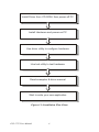
3
Chapter 1
Install Driver from CD-ROM, then power-off PC
Install Hardware and power-on PC
Use driver utility to configure hardware
Use test utility to test hardware
Read examples & driver manual
Start to write your own application
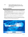
Figure 1.1: Installation Flow Chart
PCI-1752 User Manual
4
1.2 Installation Guide
Before you install your PCI-1752U/ USO card, please make sure you
have the following necessary components:
PCI-1752U/PCI-1752USO Isolated digital output card
PCI-1752U/PCI-1752USO User’s Manual
Driver software Advantech DLL drivers (included in CD-ROM)
Wiring cable PCL-10250
Wiring board ADAM-3951/ADAM-3951B
Computer PC or workstation with PCI-bus slot (Win XP/2000)
After you get the necessary components and maybe some accessories for
enhanced operation for your DAS card, you can then begin the Installation procedures. Figure 1-1 on the next page provides a concise flow
chart to give users a broad picture of the software and hardware installation procedures:
1.3 Accessories
Advantech offers a complete set of accessory products to support the PCI1752U/PCI-1752USO cards. These accessories include:
Wiring Cable
PCL-10250 The PCL-10250 shielded cable is specially designed
for PCI-1752U/PCI-1752USO card to provide high resistance to noise.
To achieve a better signal quality, the signal wires are twisted in such a
way as to form a “twisted-pair cable”, reducing crosstalk and noise from
other signal sources.
Wiring Boards
ADAM-3951/ADAM-3951B The ADAM-3951/ADAM-3951B
is a 50-pin SCSI wiring terminal module with LED indicators for DINrail mounting. This terminal module can be readily connected to the
Advantech PC-Lab cards and allow easy yet reliable access to individual
pin connections for the PCI-1752U/PCI-1752USO card. (ADAM-3951
can be used with PCI-1752U while ADAM-3951B can be used with both
PCI-1752U and PCI-1752USO)
5
Chapter 1
PCI-1752 User Manual
6
CHAPTER
2
2
Installation
Sections include:
• Unpacking
• Driver Installation
• Hardware Installation
• Device Setup and Configuration
• Device Testing
Chapter 2 Installation
This chapter gives users a package item checklist, proper instructions
about unpacking and step-by-step procedures for both driver and card
installation.
2.1 Unpacking
After receiving your PCI-1752U/PCI-1752USO package, please inspect
its contents first. The package should contain the following items:
;
PCI-1752U/PCI-1752USO card
;
Companion CD-ROM (DLL driver included)
;
User Manual
The PCI-1752U/PCI-1752USO card harbors certain electronic components that are vulnerable to electrostatic discharge (ESD). ESD could
easily damage the integrated circuits and certain components if preventive measures are not carefully paid attention to.
Before removing the card from the antistatic plastic bag, you should
take following precautions to ward off possible ESD damage:
• Touch the metal part of your computer chassis with your hand to discharge static electricity accumulated on your body. Or one can also use
a grounding strap.
• Touch the antistatic bag to a metal part of your computer chassis before
opening the bag.
• Take hold of the card only by the metal bracket when removing it out of
the bag.
After taking out the card, first you should:
• Inspect the card for any possible signs of external damage (loose or
damaged components, etc.). If the card is visibly damaged, please
notify our service department or our local sales representative immediately. Avoid installing a damaged card into your system.
Also pay extra caution to the following aspects to ensure proper installation:
Avoid physical contact with materials that could hold static electricity such as plastic, vinyl and Styrofoam.
Whenever you handle the card, grasp it only by its edges. DO NOT
TOUCH the exposed connector pins or the electronic components.
PCI-1752 User Manual
8
Note:
Keep the antistatic bag for future use. You
might need the original bag to store the card if
you have to remove the card from PC or transport it elsewhere.
2.2 Driver Installation
We recommend you to install the driver before you install the PCI1752U/PCI-1752USO card into your system, since this will guarantee
a smooth installation process.
The 32-bit DLL driver Setup program for the PCI-1752U/PCI-1752USO
card is included on the companion CD-ROM that is shipped with your
DAS card package. Please follow the steps below to install the driver
software:
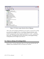
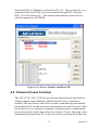
Step 1: Insert the companion CD-ROM into your CD-ROM drive.
Step 2: The Setup program will be launched automatically if you have
the autoplay function enabled on your system. When the Setup Program
is launched, you’ll see the following Setup Screen.
Figure 2.1: Advantech Automation Software Setup
9
Chapter 2
Note:
If the autoplay function is not enabled on your
computer, use Windows Explorer or Windows
Run command to execute
AUTORUN.EXE on the companion CD-ROM.
Step 3: Click Continue, and select the Installation option.
Step 4: Select the specific device and then just follow the installation
instructions step by step to complete your device driver installation and
setup.
For further information on driver-related issues, an online version of the
Device Drivers Manual is available by accessing the following path:
Start\Programs\Advantech Automation \Advantech Device Manager\Device Driver’s Manual.
2.3 Hardware Installation
Note:
Make sure you have installed the driver first
before you install the card (please refer to Section 2.2 Driver Installation)
After the DLL driver installation is completed, you can now go on to
install the PCI-1752U/PCI-1752USO card in any PCI slot on your computer. But it is suggested that you should refer to the computer user manual or related documentations if you have any doubt. Please follow the
steps below to install the card on your system.
Step 1: Turn off your computer and unplug the power cord and cables.
TURN OFF your computer before installing or removing any components on the computer.
Step 2: Remove the cover of your computer.
Step 3: Remove the slot cover on the back panel of your computer.
Step 4: Touch the metal part on the surface of your computer to neutralize
the static electricity that might be on your body.
Step 5: Adjust DIP switch SW1 on board to set the card’s board ID.
PCI-1752 User Manual
10
Step 6: Insert the PCI-1752U/PCI-1752USO card into a PCI slot. Hold
the card only by its edges and carefully align it with the slot. Insert the
card firmly into place. Use of excessive force must be avoided, otherwise
the card might be damaged.
Step 7: Fasten the bracket of the PCI card on the back panel rail of the
computer with screws.
Step 8: Connect appropriate accessories (100-pin cable, wiring terminals, etc. if necessary) to the PCI card.
Step 9: Replace the cover of your computer chassis. Re-connect the
cables you removed in step 2.
Step10: Plug in the power cord and turn on the computer.
Note:
In case you installed the card without installing
the DLL driver first, Windows XP/2000 will recognize your card as an “unknown device” after
reboot, and will prompt you to provide necessary driver. You should ignore the prompting
messages (just click the Cancel button) and
set up the driver according to the steps
described in Section 2.2 Driver Installatio
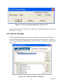
After the PCI-1752U/PCI-1752USO card is installed, you can verify
whether it is properly installed on your system in the Device Manager:
1.
Access the Device Manager through Control Panel/System/Device
Manager.
2.
The device name of the PCI-1752U/PCI-1752USO should be listed
on the Device Manager tab on the System Property Page.
11
Chapter 2
Figure 2.2: Device name listed on Device Manager
After your card is properly installed on your system, you can now configure your device using the Device Installation Program that has itself
already been installed on your system during driver setup. A complete
device installation procedure should include device setup, configuration
and testing. The following sections will guide you through the Setup,
Configuration and Testing of your device.
2.4 Device Setup & Configuration
On the Device Setting dialog box (Fig. 2-3), you can enable/disable the
Channel-Freeze function of PCI-1752U/PCI-1752USO.
PCI-1752 User Manual
12
Figure 2.3: Device Setting dialog box of PCI-1752
If you want to test the card device further, go right to the next section on
the Device Testing.
2.5 Device Testing
Following through the Setup and Configuration procedures to the last
step described in the previous section, you can now proceed to test the
device by clicking the Test Button on the I/O Device Manager dialog box
(Fig. 2-4).
Figure 2.4: Advantech Device Manager
13
Chapter 2
On the Device Test dialog box, users are free to test various functions of
PCI-1752U/PCI-1752USO on the Digital output tab.
Testing Digital Output Function
Click the Digital Output tab to bring up the Digital Output test panel such
as seen on the next page. By pressing the buttons on each tab, users can
easily set each digital output channel as high or low for the corresponding
port.
Figure 2.5: Digital Output in Device Test dialog box
Only after your card device is properly set up, configured and tested, can
the device installation procedure be counted as complete. After the
device installation procedure is completed, you can now safely proceed to
the next chapter, Signal Connections.
PCI-1752 User Manual
14
CHAPTER
3
2
Signal Connections
Sections include:
• Location of Jumpers and DIP switch
• I/O Connector Pin Assignment
• Isolated Digital Output Connections
• Field Wiring Considerations
Chapter 3 Signal Connections
Maintaining signal connections is one of the most important factors in
ensuring that your application system is sending and receiving data correctly. A good signal connection can avoid unnecessary and costly damage to your PC and other hardware devices. This chapter provides useful
information about how to connect input and output signals to the PCI1752U/PCI-1752USO via the I/O connector.
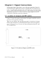
3.1 Location of Jumpers and DIP switch
Figure 3-2 shows the names and locations of jumpers and DIP switch on
the PCI-1752U and PCI-1752USO.
There are two jumpers, JP1 and JP2 on the PCI-1752U/PCI-1752USO.
Please refer to Section 3.3 Isolated Digital Output Connection and Section 4.2 Channel-Freeze Function for more information about JP1 and
JP2 configurations.
Figure 3.1: Location of Jumpers and DIP switch
PCI-1752 User Manual
16
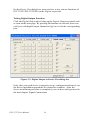
3.2 I/O Connector Pin Assignment
The I/O connector on the PCI-1752U/PCI-1752USO is a 100-pin connector that enable you to connect to accessories with the PCL-10250 shielded
cable.
Figure 3-1 shows the pin assignments for the 100-pin I/O connector on
the PCI-1752U/PCI-1752USO, and Table 3-1 shows its I/O connector
signal description.
Note:
The PCL-10250 shielded cable is especially
designed for the PCI-1752U/ USO to reduce
noise in the analog signal lines. Please refer to
Section 1.3 Accessories.
17
Chapter 3
Figure 3.2: I/O Connector Pin Assignments
PCI-1752 User Manual
18
Table 3.1: I/O Connector Signal Descriptions
Signal Name
Reference
Direction
Description
IDO<00...15>
PCOM0
Output
Isolated digital output of
group 0
IDO<16...31>
PCOM1
Output
Isolated digital output of
group 1
IDO<32...47>
PCOM2
Output
Isolated digital output of
group 2
IDO<48...63>
PCOM3
Output
Isolated digital output of
group 3
PCOM0
-
Input
Common pin for inductive
loads of isolated output
channels IDO00~IDO15
PCOM1
-
Input
Common pin for inductive
loads of isolated output
channels IDO16~IDO31
PCOM2
-
Input
Common pin for inductive
loads of isolated output
channels IDO32~IDO47
PCOM3
-
Input
Common pin for inductive
loads of isolated output
channels IDO48~IDO63
IGND
-
-
Isolated ground
CH_FRZ_IN
CH_FRZ_COM
Input
Channel-Freeze function
input pin
CH_FRZ_COM
-
Input
Common pin for ChannelFreeze function input
19
Chapter 3
3.3 Isolated Digital Output Connections
Power On Configuration
Default configuration after power on, and hardware reset is to set all the
isolated output channels to open status
( the current of the load can’t be sink) so that users need not worry about
damaging external devices during system startup or reset.
When the system is hot reset, then the status of isolated digital output
channels are selected by jumper JP1. Table 3-2 shows the configuration
of jumper JP1.
Table 3.2: Power on configuration after hot reset
PCI-1752 JP1
Power on configuration after hot reset
Keep last status after hot reset
1
Load default configuration (Default setting)
1
Isolated Outputs
Each of isolated output channels comes equipped with a Darlington transistor. Every 16 output channels share common collectors and integral
suppression diodes for inductive loads.
Note:
If an external voltage (5 ~ 40 VDC) is applied to
an isolated output channel while it is being used
as an output channel, the current will flow from
the external voltage source to the card. Please
take care that the current through each IDO pin
not exceed 200 mA.
PCI-1752 User Manual
20
Figure 3-3 shows how to connect an external output load to the card’s isolated outputs.
Figure 3.3: Isolated DO: PCI-1752U (sink type)
Figure 3.4: Isolated DO: PCI-1752USO (source type)
21
Chapter 3
3.4 Field Wiring Considerations
When you use the PCI-1752U/PCI-1752USO to acquire data from outside, noises in the environment might significantly affect the accuracy of
your measurements if due cautions are not taken. The following measures
will be helpful to reduce possible interference running signal wires
between signal sources and the PCI-1752U/PCI-1752USO.
•
The signal cables must be kept away from strong electromagnetic
sources such as power lines, large electric motors, circuit breakers
or welding machines, since they may cause strong electromagnetic
interference. Keep the analog signal cables away from any video
monitor, since it can significantly affect a data acquisition system.
•
If the cable travels through an area with significant electromagnetic
interference, you should adopt individually shielded, twisted-pair
wires as the analog input cable. This type of cable has its signal
wires twisted together and shielded with a metal mesh. The metal
mesh should only be connected to one point at the signal source
ground.
•
Avoid running the signal cables through any conduit that might
have power lines in it.
•
If you have to place your signal cable parallel to a power line that
has a high voltage or high current running through it, try to keep a
safe distance between them. Or you should place the signal cable at
a right angle to the power line to minimize the undesirable effect.
•
The signals transmitted on the cable will be directly affected by the
quality of the cable. In order to ensure better signal quality, we recommend that you use the PCL-10250 shielded cable.
PCI-1752 User Manual
22
CHAPTER
4
2
Operation
Sections include:
• Board ID
• Channel-Freeze Function
Chapter 4 Operation
This chapter describes the operation of the PCI-1752U/PCI-1752USO.
The software driver provided allows users to access all of the card’s functions without register level programming. For users who prefer to implement their own bit-level programming, please refer to the information in
this chapter.
4.1 Board ID
The PCI-1752/PCI-1752USO have a built-in DIP switch (SW1), which is
used to define each card’s board ID. You can determine the board ID on
the register as shown on Table 4-1. When there are multiple cards on the
same chassis, this board ID setting function is useful for identifying each
card’s device number through board ID. We set the PCI-1752/PCI1752USO board ID as 0 at the factory. If you need to adjust it to other
board ID, set the SW1 by referring to the Table 4-2.
Table 4.1: Board ID register
Base Add.+decimal
3
2
1
0
Abbreviation
ID3
ID2
ID1
ID0
ID0: the least significant bit (LSB) of Board ID
ID3: the most significant bit (MSB) of Board ID
Table 4.2: Board ID setting
Board ID(dec)
Switch Position
3
2
1
0
*0
l
l
l
l
1
l
l
l
°
°
°
°
l
°
°
°
°
:
14
15
{ = Off
l = On
* = default
There are two ways to make association of the device number with the
corresponding board ID. The first way is to check the content in the
PCI-1752 User Manual
24
Advantech Device Manager, as shown in Fig. 4-1. The second way is to
determine the board ID by its device number through DLL function,
DRV_DeviceGetFeatures( ). For detailed information, please refer to
software manual on CD-ROM.
Figure 4.1: Device Number and Board ID
4.2 Channel-Freeze Function
The PCI-1752U/PCI-1752USO provide the channel-freeze function for
isolated digital output channels. When Channel-Freeze function is
enabled, all ports on the card will be locked so that the data transmitted
(from the host PC) to the card won’t be transferred to the DO ports. Once
the Channel-Freeze function is enabled, each port status is immediately
frozen into its last valid value before the Channel-Freeze. Since the value
transmitted (from the host PC) to the card is also stored in the buffers on
25
Chapter 4
PC, thus when user calls the DRV_DioGet CurrentDOByte ( ) function to
read back the DO channel value, this function will determine that:
• If Channel-Freeze function is disabled, it will return the DO value on
the port;
• If Channel-Freeze function is enabled, it will return the value from the
buffers on host PC.
The PCI-1752U/PCI-1752USO provides a digital input channel
(CH_FRZ_IN) to enable the channel-freeze function. The channel-freeze
function acts when the pin CH_FRZ_IN is activated. Moreover, you can
setup the input mode of channel-freeze function input channel
CH_FRZ_IN as dry contact input mode or wet contact input mode
selected by on-board jumper JP2, as shown in Table 4-3. The wiring in
wet contact and dry contact input mode are shown in Figure 4-2. Otherwise, you also can enable the function through software by writing “1” to
CFC (Channel-Freeze Function Control) bit on channel-freeze function
register, as shown in Table 4-4 and Table 4-5. It’s useful in software simulation and testing program.
The CFS (Channel-Freeze Function Status) bit shows the status of Channel-Freeze function:
A value of 1 for the CFS bit indicates an active Channel-Freeze Function;
whereas a value of 0 indicates a non-active Channel-Freeze Function.
Table 4.3: JP2: Channel-Freeze function input mode
1
1
Channel-Freeze function dry contact input mode
Channel-Freeze function wet contact input mode
PCI-1752 User Manual
26
Internal
Extrernal
Internal
Extrernal
CH_FRZ_IN
NC
10 ~ 50 V
CH_FRZ_IN
Vin
CH_FRZ_COM
CH_FRZ_COM
IGND
(a) For Wet Contact
(b) For Dry Contact
Figure 4.2: Wiring in wet/dry contact input mode
Table 4.4: Channel-Freeze function register
Base Add.+decimal
3
2
Abbreviation
1
0
CH_FRZ_ON
CH_FRZ_EN
Table 4.5: Channel-Freeze function bit value
CH_FRZ_EN
Channel-Freeze function control
0
Disable
1
Enable
CH_FRZ_ON
Channel-Freeze function flag
0
OFF
1
ON
27
Chapter 4
PCI-1752 User Manual
28
APPENDIX
A
2
Specifications
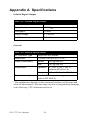
Appendix A Specifications
Isolated Digital Output
Table A.1: Isolated Digital Output
Number of Output Channels
64
Optical Isolation
2500 VDC
Throughput
10 kHZ1
Supply Voltage
5 ~ 40 VDC
Sink Current
200 mA max/channel
General
Table A.2: General Specifications
I/O Connector Type
100-pin SCSI-II female
Dimensions
175 mm x 100 mm (6.9" x 3.9")
Power Consumption
Typical
Max.
+5V @ 500 mA
Temperature
Operation
0 ~ +60 °C (32 ~ 140 °F)
(refer to IEC 68-2-1,2)
Storage
-20 ~ +70 °C (-4 ~ 158 °F)
Relative Humidity
+5V @ 230 mA
5 – 95 % RH non-condensing
(refer to IEC 68-2-3)
1
Throughput rate depends on the computer hardware architecture and
software environment. The rates may vary due to programming language,
code efficiency, CPU utilization and so on.
PCI-1752 User Manual
30
APPENDIX
B
2
Block Diagram
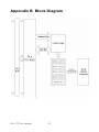
Appendix B Block Diagram
PCI-1752 User Manual
32
C
APPENDIX
2
Register Structure and
Format
Appendix C Register Structure & Format
C.1 Overview
The PCI-1752U/ USO is delivered with an easy-to-use 32-bit DLL driver
for user programming under the Windows XP/2000 operating system.
We advise users to program the PCI-1752U/ USO using the 32-bit DLL
driver provided by Advantech to avoid the complexity of low-level programming by register.
The most important consideration in programming the PCI-1752U/ USO
at the register level is to understand the function of the card's registers.
The information in the following sections is provided only for users who
would like to do their own low-level programming.
C.2 I/O Port Address Map
The PCI-1752U/ USO requires 32 consecutive addresses in the PC's I/O
space. The address of each register is specified as an offset from the
card's base address. For example, BASE+0 is the card's base address and
BASE+7 is the base address plus seven bytes.
PCI-1752 User Manual
34
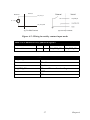
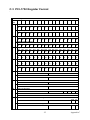
C.3 PCI-1752 Register Format
PCI-1752 Register Format
Base
Add.
0
15
14
13
12
11
10
9
8
7
6
5
4
3
2
1
0
R Digital Output Group 0 Read Back
DO
15
DO DO DO
14 13 12
DO DO
11 10
DO DO DO DO DO DO DO
9
8
7
6
5
4
3
DO DO
2
1
DO
0
DO DO DO DO DO DO DO
9
8
7
6
5
4
3
DO DO
2
1
DO
0
DO DO DO DO DO DO DO
25 24 23 22 21 20 19
DO DO
18 17
DO
16
DO DO DO DO DO DO DO
25 24 23 22 21 20 19
DO DO
18 17
DO
16
DO DO DO DO DO DO DO
41 40 39 38 37 36 35
DO DO
34 33
DO
32
DO DO DO DO DO DO DO
41 40 39 38 37 36 35
DO DO
34 33
DO
32
DO DO DO DO DO DO DO
57 56 55 54 53 52 51
DO DO
50 49
DO
48
DO DO DO DO DO DO DO
57 56 55 54 53 52 51
DO DO
50 49
DO
48
ID3
ID2 ID1
ID0
W Digital Output Group 1
DO
15
2
DO DO DO
14 13 12
DO DO
11 10
R Digital Output Group 1 Read Back
DO
31
DO DO DO
30 29 28
DO DO
27 26
W Digital Output Group 1
DO
31
4
DO DO DO
30 29 28
DO DO
27 26
R Digital Output Group 2 Read Back
DO
47
DO DO DO
46 45 44
DO DO
43 42
W Digital Output Group 2
DO
47
6
DO DO DO
46 45 44
DO DO
43 42
R Digital Output Group 3 Read Back
DO
63
DO DO DO
62 61 60
DO DO
59 58
W Digital Output Group 3
DO
63
8
DO DO DO
62 61 60
DO DO
59 58
R N/A
W N/A
A
R N/A
W N/A
10 R Board ID Register
W N/A
12 R Channel-Freeze Function Control Register
CFS CF
C
W Channel-Freeze Function Status Register
CF
C
35
Appendix C
PCI-1752 User Manual
36
D
APPENDIX
2
ADAM-3951/
ADAM-3951B
Pin Assignments
Appendix D ADAM-3951/3951B
Pin Assignments
PCI-1752 User Manual
38
39
Appendix D
PCI-1752 User Manual
40