1
Multimedia Projector
Quick Reference Guide
103-011100-01
English
MODEL
Deutsch
READ THE SAFETY INSTRUCTIONS IN THE OWNER’S MANUAL
(CD-ROM) BEFORE USING THE PROJECTOR.
Italiano
Use this book as a reference guide when setting up the projector.
For detailed information about installation, setup, and operation of
the projector, refer to the owner’s manual on the CD-ROM.
Español
Français
✽ Projection lens is optional.
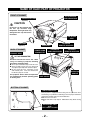
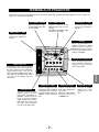
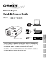
NAME OF EACH PART OF PROJECTOR
FRONT OF CABINET
TOP CONTROLS
AND INDICATORS
PROJECTION LENS
(optional)
CAUTION
Do not turn on the projector with
the lens cap attached. High
temperature from light beam may
damage the lens cap and result in
fire hazard.
AIR INTAKE
VENT
LENS CAP
(optional)
BACK OF CABINET
EXHAUST VENT
SPEAKERS
POWER CORD
CONNECTOR
INFRARED
REMOTE RECEIVER
TERMINALS
AND CONNECTORS
INFRARED
REMOTE RECEIVER
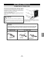
HOT AIR EXHAUSTED !
Air blown from exhaust vent is hot. When
using or installing a projector, following
precautions should be taken.
● Do not put a flammable object near this vent.
● Keep rear grills at least 3.3’(1 m) away from
any object, especially heat-sensitive object.
● Do not touch this area, especially screws
and metallic parts. This area will become
hot while a projector is used.
This projector detects internal temperature
and automatically controls operating power LAMP COVER
of Cooling Fans.
CARRYING
HANDLE
BOTTOM OF CABINET
AIR INTAKE VENTS
This projector is equipped with cooling fans for protection from
overheating. Pay attention to following to ensure proper ventilation
and avoid a possible risk of fire and malfunction.
● Do not cover vent slots.
● Keep side clear of any objects. Obstructions may block cooling
air.
ADJUSTABLE FEET
AND
FEET LOCK LATCHES
-2-
SETTING-UP PROJECTOR
CONNECTING AC POWER CORD
This projector uses nominal input voltages of 100-120 V or 200-240
V AC. This projector automatically selects correct input voltage. It
is designed to work with single-phase power systems having a
grounded neutral conductor. To reduce risk of electrical shock, do
not plug into any other type of power system.
Consult your authorized dealer or service station if you are not sure
of type of power supply being in use.
Connect a projector with a peripheral equipment before turning a
projector on.
CAUTION
For safety, unplug AC Power Cord when an appliance is not
used.
When this projector is connected to outlet with AC Power Cord,
an appliance is in Stand-by Mode and consumes a little electric
power.
Connect AC Power Cord (supplied) to a projector.
AC outlet must be near this equipment and must
be easily accessible.
CAUTION
The AC Power Cord must meet the requirement of the country where you use the projector.
Confirm the AC plug type with the chart below. The proper AC Power Cord must be used.
If the supplied AC Power Cord does not match the AC outlet, contact your sales dealer.
AC Outlet side
Projector side
For U.S.A. and Canada
For Continental Europe
To POWER CORD
CONNECTOR on the
projector.
English
Ground
To AC Outlet.
(120 V AC)
To AC Outlet.
(200 - 240 V AC)
-3-
LENS INSTALLATION
Before setting up a projector, install Projection Lens on
Projector.
1. Before installation, check where a projector is used and
prepare a suitable lens. For specifications of a Projection
Lens, contact sales dealer where you purchased a projector.
2. For installation, refer to installation manual in the optional
lens.
NOTE;
COVER CAP
When installing the lens, remove the cover cap in the
projector.
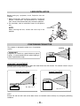
POSITIONING PROJECTOR
This projector is designed to project on a flat projection
surface.
SCREEN
ROOM LIGHT
Brightness in a room has a great influence on picture
quality. It is recommended to limit ambient lighting in
order to provide best image.
LENS SHIFT ADJUSTMENT
Projection lens can be moved up and down with motor-driven lens shift function. This function makes it easy to
provide projected image where you want.
Highest Lens Shift
Lowest Lens Shift
H3
H1
H4
H2
H1 : H2 = 6 : 1
H3 : H4 = 1 : 1
NOTE
Screen size and lens shift ratio on the above charts are standard values and they may change by positioning
conditions.
-4-
ADJUSTABLE FEET
Picture tilt and projection angle can be adjusted by
rotating ADJUSTABLE FEET. Projection angle can be
adjusted to 10.5 degrees.
1
Lift front of a projector and pull FEET LOCK LATCHES
on both sides of a projector.
2
Release FEET LOCK LATCHES to lock ADJUSTABLE
FEET and rotate ADJUSTABLE FEET to fine tune
position and tilt.
3
To shorten ADJUSTABLE FEET, lift front of a projector
and pull and undo FEET LOCK LATCHES.
Position and keystone distortion of image can be adjusted
using Menu Operation.
ADJUSTABLE FEET
FEET LOCK
LATCHES
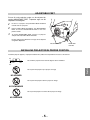
INSTALLING PROJECTOR IN PROPER POSITION
Install the projector properly. Improper installation may reduce the lamp lifetime and cause a fire hazard.
10˚
Do not tilt the projector more than 10 degrees above and below.
Do not point the projector up to project an image.
NO UPWARD
Do not point the projector down to project an image.
NO DOWNWARD
Do not put the projector on either side to project an image.
NO SIDEWAYS
-5-
English
10˚
MOVING PROJECTOR
Use Carrying Handle when moving a projector.
When moving a projector, replace lens cap and retract
feet to prevent damage to lens and cabinet.
When this projector is not in use for an extended period,
put it into case (not supplied with this projector).
CAUTION IN CARRYING OR TRANSPORTING A PROJECTOR
● Do not drop or bump a projector, otherwise damages or malfunctions may result.
● When carrying a projector, use a suitable carrying case.
● Do not transport a projector by using a courier or transport service in an unsuitable transport case. This
may cause damage to a projector. To transport a projector through a courier or transport service, consult
your dealer for best way.
-6-
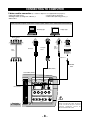
TERMINALS OF PROJECTOR
This projector has input and output terminals on its back for connecting computers and video equipment. Refer to figures on
pages 12 to 14 and connect properly.
INPUT TERMINAL (DIGITAL)
INPUT TERMINAL (ANALOG)
AUDIO INPUT 2 JACK
Connect computer output
(Digital DVI-D type) to this
terminal.
HD (HDCP Compatible) signal
can also be connected.
Connect computer output
(Analog HDB 15 pin type)
to this terminal.
AUDIO INPUT 1 JACK
Connect an audio output
(stereo) from computer to
this jack.
Connect an audio output
(stereo) from computer to
this jack.
R/C JACK
INPUT 1
ANALOG
DIGITAL(DVI-D)
R/C JACK
AUDIO 1
When using Wired/Wireless
Remote Control Unit as Wired
Remote Control, Connect
Wired Remote Control Unit to
this jack with Remote Control
Cable (not supplied).
CONTROL PORT
RESET
AUDIO 2
CONTROL PORT CONNECTOR
This projector uses a micro processor
to control this unit, and occasionally,
this micro processor may malfunction
and need to be reset. This can be
done by pressing RESET button with a
pen, which will shut down and restart
unit. Do not use RESET function
excessively.
5 BNC INPUT JACKS
Connect component video
output (Y, Cb, Cr or Y, Pb, Pr)
from video equipment to
VIDEO/Y, Cb/Pb and Cr/Pr
jacks or connect computer
output {5 BNC Type (Green,
Blue, Red, Horiz. Sync and
Vert. Sync.)} from computer
to G, B, R, H/V and V jacks.
B
R
VIDEO/Y
Cb/Pb
H/V
V
Cr/Pr
INPUT 2
VIDEO/Y Cb/Pb
Cr/Pr
R–AUDIO–L
S–VIDEO
When controlling the projector
from a computer, connect the
computer to this connector
with a control cable.
(MONO)
INPUT 3
English
RESET BUTTON
G
VIDEO INPUT JACKS
AUDIO INPUT JACKS
S-VIDEO INPUT JACK
Connect composite video
output from video equipment
to VIDEO/Y jack or connect
component video outputs to
VIDEO/Y, Cb/Pb and Cr/Pr
jacks.
Connect an audio output
from video equipment to
these jacks.
When the audio output is
monaural, connect it to
L (MONO) jack.
Connect S-VIDEO
output from video
equipment to this
jack.
-7-
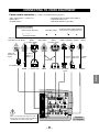
CONNECTING TO COMPUTER
Cables used for connection
(✽ = Cable or adapter is not supplied with this projector.)
• VGA Cable (HDB 15 pin)
• Control Cable for Serial Port
• DVI-Digital Cable (for Single Link T.M.D.S.) ✽
• Audio Cables (Mini Plug (stereo) ) ✽
• BNC Cable ✽
IBM-compatible computer or Macintosh computer (VGA / SVGA / XGA / SXGA/SXGA+/WXGA/UXGA)
Desktop type
Monitor Output
Monitor Output
Laptop type
Audio Output
Monitor Output
Audio
Cable ✽
(stereo)
DVI-Digital
Cable ✽
VGA Cable
BNC
Cable ✽
Serial port
Control Cable
for Serial Port
Terminal
AUDIO IN 1 or 2
CONTROL
PORT
INPUT TERMINAL (DIGITAL)
INPUT TERMINAL (ANALOG)
INPUT 1
ANALOG
DIGITAL(DVI-D)
R/C JACK
5 BNC (G/B/R/HV/V)
CONTROL PORT
RESET
AUDIO 1
AUDIO 2
G
B
R
VIDEO/Y
Cb/Pb
H/V
V
Cr/Pr
INPUT 2
VIDEO/Y Cb/Pb
Cr/Pr
R–AUDIO–L
(MONO)
INPUT 3
Terminals
of a Projector
-8-
S–VIDEO
Note:
When connecting the cable, the power
cords of both the projector and the
external equipment should be
disconnected from AC outlet.
CONNECTING TO VIDEO EQUIPMENT
Cables used for connection
(✽ = Cable is not supplied with this projector.)
• Video Cable (RCA x 1 or RCA x 3) ✽
• BNC Cable ✽
• S-VIDEO Cable ✽
• DVI-Digital Cable (for Single Link T.M.D.S.) ✽
• Audio Cable (RCA x 2) ✽
• HDB 15 pin-SCART 21 pin Cable ✽
Video Source (example)
Video Cassette Recorder
Component video output equipment.
(such as DVD player or high-definition TV source.)
Video Disc Player
Composite Component Video Composite Component Video
RGB Scart
Digital Output
21-pin Output Video Output
(HDCP compatible)
Output
Video Output
Output
(Y, Cb/Pb, Cr/Pr)
(Y, Cb/Pb, Cr/Pr)
HDB 15 pinSCART 21 pin
Cable ✽
Video Cables
(RCA x 1 or
RCA x 3) ✽
DVI-Digital
Cable ✽
Audio
Output
S-VIDEO
Output
Audio Cable
(RCA x 2) ✽
S-VIDEO
Cable ✽
BNC Cable ✽
INPUT TERMINAL (ANALOG)
VIDEO
Y - Cb/Pb - Cr/Pr
VIDEO
Y - Cb/Pb - Cr/Pr INPUT TERMINAL AUDIO IN
S-VIDEO
English
(DIGITAL)
INPUT 1
DIGITAL(DVI-D)
ANALOG
R/C JACK
AUDIO 1
CONTROL PORT
RESET
AUDIO 2
G
B
R
VIDEO/Y
Cb/Pb
H/V
V
Cr/Pr
INPUT 2
VIDEO/Y Cb/Pb
Cr/Pr
R–AUDIO–L
S–VIDEO
(MONO)
Note:
When connecting the cable, the power cords of
both the projector and the external equipment
should be disconnected from AC outlet.
INPUT 3
Terminals
of a Projector
-9-
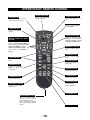
OPERATION OF REMOTE CONTROL
AUTO PC ADJ. BUTTON
LIGHT BUTTON
Lights the buttons on the remote
control for about 10 seconds.
POWER ON-OFF BUTTON
Used to operate AUTO PC
Adjustment function.
Used to turn projector on or
off.
COLOR M. BUTTON
Used to operate COLOR
MANAGEMENT.
MENU BUTTON
Used to select MENU
operation.
ON-OFF
MENU
-I
COLOR M.
VOLUME+
Used to select an item or adjust
value in ON-SCREEN MENU.
They are also used to pan image
in DIGITAL ZOOM +/– mode.
POINT LEFT/RIGHT buttons are
also used as VOLUME +/–
buttons.
VOLUME-
POINT (UP / DOWN / LEFT / RIGHT)
BUTTONS
LIGHT AUTO PC
AUTO
SELECT
IMAGE
INPUT BUTTON
1
Used to select input
source.
2
I
SELECTION
I
3
Used to select DIGITAL
ZOOM +/– mode and
resize image.
IMAGE ADJ. BUTTON
Used to adjust image
level.
INPUT
INPUT
D.ZOOM BUTTON
SELECT BUTTON
Used to execute item
selected. It is also used to
expand / compress image
in DIGITAL ZOOM mode.
D.ZOOM
FREEZE
NO SHOW
KEYSTONE
SCREEN
KEYS.
MUTE
L
LENS
L
F
FOCUS
F
Z
ZOOM
Z
SCREEN BUTTON
IMAGE BUTTON
Used to select image
level.
NO SHOW BUTTON
Used to turn picture into
black image.
FREEZE BUTTON
Used to freeze picture.
MUTE BUTTON
Used to mute sound.
Used to select screen.
KEYSTONE BUTTON
Used to correct
keystone distortion.
LENS SHIFT BUTTON
Used to select LENS
SHIFT function.
ZOOM BUTTON
Used to adjust zoom.
WIRED REMOTE JACK
When using as Wired Remote
Control, connect Remote
Control Cable to this jack.
Battery installation is required
when using as Wired Remote
Control.
FOCUS BUTTON
Used to adjust focus.
- 10 -
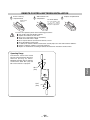
REMOTE CONTROL BATTERIES INSTALLATION
1
Remove battery
compartment lid.
2
Slide batteries into
compartment.
3
Replace compartment lid.
Two AA size batteries
For correct polarity (+ and
–), be sure battery
terminals are in contact
with pins in compartment.
Pull up lid and
remove it.
To insure safe operation, please observe following precautions :
● Use (2) AA or LR6 type alkaline batteries.
● Replace two batteries at same time.
● Do not use a new battery with an used battery.
● Avoid contact with water or liquid.
● Do not expose Remote Control Unit to moisture, or heat.
● Do not drop Remote Control Unit.
● If a battery has leaked on Remote Control Unit, carefully wipe case clean and install new batteries.
● Danger of explosion if battery is incorrectly replaced.
● Dispose of used batteries according to batteries manufacturers instructions and local rules.
Operating Range
Point Remote Control Unit toward
projector (Infrared Remote Receiver)
whenever pressing any button.
Maximum operating range for Remote
Control Unit is about 16.4’ (5m) and
60° in front and rear of a projector.
60°
English
16.4’
(5 m)
16.4’
(5 m)
60°
- 11 -
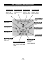
TOP CONTROLS AND INDICATORS
This projector has CONTROL BUTTONS (TOP CONTROLS) and INDICATORS on its top.
LAMP REPLACE INDICATOR
WARNING TEMP. INDICATOR
READY INDICATOR
LAMP INDICATOR
Turns to yellow when
life of projection lamp
draws to an end.
Flashes yellow when
the lamp cannot light
up.
Flashes red when
internal
projector
temperature is too
high.
Lights green when a
projector is ready to be
turned on.
And it
flashes green in Power
Management mode.
Becomes dim when a
projector is turned on.
And bright when a
projector is in stand-by
mode.
POWER ON–OFF BUTTON
Used to turn a projector
on or off.
MENU BUTTON
Used to open or close
MENU operation.
INPUT BUTTON
Used to select input
source.
ZOOM BUTTON
Used to adjust zoom.
AUTO PC ADJ. BUTTON
Used to operate AUTO
PC Adjustment function.
FOCUS BUTTON
Used to adjust focus.
IMAGE BUTTON
Used to select image
level.
LENS SHIFT BUTTON
SELECT BUTTON
Used to select LENS
SHIFT function.
POINT (VOLUME + / – ) BUTTONS
Used to select an item or adjust value
in ON-SCREEN MENU. They are also
used to pan image in DIGITAL ZOOM
+/– mode.
POINT LEFT/RIGHT buttons are also
used as VOLUME +/– buttons.
- 12 -
Used to execute the
selected item.
It is also used to
expand/compress image
in DIGITAL ZOOM mode.
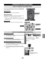
OPERATING ON-SCREEN MENU
HOW TO OPERATE ON-SCREEN MENU
You can control and adjust this projector through ON-SCREEN
MENU. Refer to following pages to operate each adjustment on
ON-SCREEN MENU.
REMOTE CONTROL UNIT
ON-OFF
1 DISPLAY MENU
Press MENU button to display ON-SCREEN MENU.
LIGHT AUTO PC
AUTO
MENU
✽ Pointer is icon on ON-SCREEN MENU to select item. See
figures on section "FLOW OF ON-SCREEN MENU
OPERATION" below.
VOLUME-
SELECT
Used to move a
Pointer UP/ DOWN/
RIGHT/ LEFT.
INPUT
BUTTON
MENU BUTTON
INPUT SELECT
IMAGE
1
3 SELECT ITEM
Select item or set selected function by pressing SELECT button.
POINT BUTTONS
COLOR M.
VOLUME+
2 MOVING POINTER
Move pointer (✽ see below) or adjust value of item by pressing
POINT buttons on Top Control or on Remote Control Unit.
-I
TOP CONTROL
2
3
Used to select
the item.
I
D.ZOOM
SELECTION
I
FREEZE
NO SHOW
KEYSTONE
SCREEN
KEYS.
MUTE
MENU BUTTON
L
LENS
L
F
FOCUS
F
Z
ZOOM
Z
POINT BUTTONS
Used to move a
Pointer UP/ DOWN/
RIGHT/ LEFT.
SELECT BUTTON
Used to select item.
FLOW OF ON-SCREEN MENU OPERATION
Press MENU button to display ON-SCREEN MENU (MENU
BAR). A red frame is POINTER.
Select Menu to be adjusted
2
Move POINTER (red frame) to MENU ICON that you want to
select by pressing POINT RIGHT / LEFT buttons.
Contrast
English
1
MENU ICON
MENU BAR
Display ON-SCREEN MENU
Auto
POINTER (red frame)
Press POINT UP/DOWN
buttons to move POINTER.
POINTER
(red frame)
ITEM
Control or adjust item through ON-SCREEN MENU
3
4
Press POINT UP/DOWN buttons and move POINTER (red
frame or red arrow) to ITEM that you want to adjust, and then
press SELECT button to show ITEM DATA.
SELECT
BUTTON
Adjust ITEM DATA by pressing POINT RIGHT/LEFT buttons.
Refer to following pages for details of respective
adjustments.
ITEM DATA
Press POINT LEFT/RIGHT
buttons to adjust value or
set function.
- 13 -
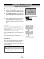
TURNING ON / OFF PROJECTOR
TURNING ON THE PROJECTOR
1
Complete peripheral connections (with a computer, VCR,
etc.) before turning on the projector.
2
Connect the projector's AC power cord into an AC outlet.
The LAMP Indicator lights RED, and READY Indicator lights
GREEN.
3
Press the POWER ON-OFF button on the top control or on
the remote control to ON. The LAMP Indicator dims, and the
cooling fans start to operate. The preparation display
appears on the screen and the count down starts.
16
4
After the count-down, the input source that was selected last
and the Lamp control status icon appear on the screen.
The preparation display disappears after 20 ~ 30 seconds.
Selected Input Source and Lamp control
Lamp control status
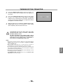
If the projector is locked with a PIN code, PIN code Input
Dialog Box will appear. Enter the PIN code as instructed
below.
PIN code Input Dialog Box
Enter a PIN code
Select a number by pressing the POINT LEFT/RIGHT button and fix the
number with the SELECT button. The number will change to "✳". If you
fixed a wrong number, move the pointer to "Set" or "Clear" once by
pressing the POINT DOWN button, then return to "PIN code". Enter the
correct number again.
Repeat this step to complete entering a four-digit number.
Pointer
When the four-digit number is fixed, the pointer will automatically move to
"Set". Press the SELECT button so that you can start to operate the
projector.
If you entered a wrong PIN code, "PIN code" and the number (✳✳✳✳) will
turn red and disappear. Enter a correct PIN code all over again.
After the OK icon
disappears, you can
operate the projector.
What is PIN code?
PIN code is a security code using Personal Identification Number that
allows the person who knows it to operate the projector. Setting PIN code
prevents others except the specific users from operating the projector.
A PIN code consists of a four-digit number. Refer to PIN Code Lock
function in Setting menu in the user’s manual for locking operation of the
projector with your PIN code.
CAUTION ON HANDLING PIN CODE
If you forget your PIN code, the projector can no
longer be started. Set a new PIN code with special
care, take a memo and keep it at hand. Should the
PIN code be missing or forgotten, consult your dealer
or service center.
- 14 -
TURNING OFF THE PROJECTOR
1
Press the POWER ON-OFF button on the top control or on
the remote control, and a message "Power off?" appears on
the screen.
2
Press the POWER ON-OFF button again to turn off the
projector. The LAMP Indicator lights bright and READY
Indicator turns off. After projector is turned off, Cooling Fans
operate (for 90 seconds). During this "Cooling Down" period,
this appliance cannot be turned on.
3
The message disappears after 4 seconds.
When the projector has cooled down, READY Indicator lights
GREEN again and you can turn projector on. After cooling
down completely, disconnect AC Power Cord.
TO MAINTAIN THE LIFE OF LAMP, ONCE YOU TURN
PROJECTOR ON, WAIT AT LEAST 5 MINUTES
BEFORE TURNING IT OFF.
DO NOT DISCONNECT AC POWER CORD WHILE
COOLING FANS ARE RUNNING OR BEFORE READY
INDICATOR LIGHTS GREEN AGAIN. OTHERWISE IT
WILL RESULT IN SHORTENING LAMP LIFE.
• The projector cannot be turned on during the cooling period with the
READY indicator turned off. You can turn it on again after the READY
indicator GREEN again.
• When the On start function is on, this projector is turned on
automatically by connecting the AC power cord to an AC outlet.
• Do not operate the projector continuously without rest. Continuous use
may result in shortening the lamp life. Turn off the projector and give it
a rest about an hour in every 24 hours.
• This projector monitors internal temperature and automatically controls
the running speed of the cooling fans.
• If the WARNING TEMP indicator flashes red, see “WARNING TEMP
INDICATOR ” in the user’s manual.
- 15 -
English
NOTE;