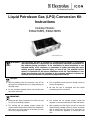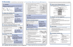
1
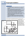
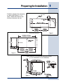
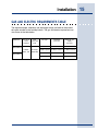
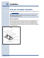
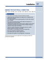
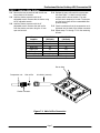
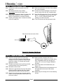
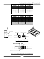
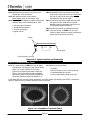
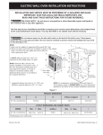
Installation Instructions
Slide In Gas Cooktop
E36GC76EPS
E48GC76EPS
5995447108
2 Safety
IMPORTANT SAFETY INSTRUCTIONS
Safety Precautions
Do not attempt to install or operate your unit until you have read the safety
precautions in this manual. Safety items throughout this manual are labeled with a
Warning or Caution based on the risk type.
Definitions
This is the safety alert symbol. It is used to alert you to potential personal
injury hazards. Obey all safety messages that follow this symbol to avoid possible
injury or death.
WARNING
WARNING indicates a potentially hazardous situation which, if not avoided, could
result in death or serious injury.
CA
UTION
CAUTION
CAUTION indicates a potentially hazardous situation which, if not avoided, may result
in minor or moderate injury.
CA
UTION
CAUTION
CAUTION used without the safety alert symbol indicates a potentially hazardous
situation which, if not avoided, may result in property damage.
IMPOR
TANT
IMPORT
Indicates installation, operation or maintenance information which is important but
not hazard related.
Safety
SAFETY PRECAUTIONS
WARNING
•
Read all instructions before using the appliance.
•
Improper installation, adjustment, alteration, service, or maintenance can cause
personal injury or property damage. Refer to these instructions and the
accompanying Use & Care Manual. For assistance or additional information,
consult a qualified installer, service agency, manufacturer (dealer), or the gas
supplier.
•
For your safety:
-
Do not obstruct the flow of combustion and ventilation air to the unit.
-
Keep appliance area clear and free from combustible material, gasoline and
other flammable vapors and liquids.
-
Do not use or attempt to use this appliance in the event of a power failure.
•
This unit is designed as a cooking appliance. Never use it for warming or heating
a room.
•
This appliance must be installed with the gas pressure regulator supplied with it.
•
Disconnect the electrical supply before installing or servicing the appliance.
•
This appliance must be grounded. Connect only to a properly grounded
electrical supply. Refer to “Electrical Requirements”.
•
Install or locate this appliance only in accordance with these installation
instructions.
•
Use this appliance only for its intended use as described in this manual. Do not
use corrosive chemicals or vapors in this appliance. This type of appliance is not
designed for industrial or laboratory use.
•
As with any appliance, close supervision is necessary when used by children.
•
Do not operate this appliance if it has a damaged electrical cord, plug, conduit or
wires, if it is not working properly, or if it has been damaged or dropped.
•
This appliance should be installed and serviced only by qualified service
personnel.
•
Some products, such as whole eggs, and sealed containers, such as closed glass
jars, may explode and should not be heated on this cooktop.
3
4 Safety
WARNING
•
Based on safety considerations, the top burner flame should be adjusted so it
does not extend beyond the edge of the cooking utensil.
•
If the information in this manual is not followed exactly, a fire or explosion
may result causing property damage, personal injury, or death.
•
What to do if you smell gas:
•
-
Do not try to light any appliance.
-
Do not touch any electrical switch, do not use any phone in your building.
-
Immediately call the gas supplier from a neighbor’s phone.
-
Follow the gas supplier’s instructions.
-
If you cannot reach your gas supplier, call the fire department.
For your safety:
-
•
Do not store or use gasoline or other flammable vapors and liquids in the
vicinity of this or any other appliance.
Installation of this appliance must be performed by a qualified installer, service
agency or the gas supplier. Contact the nearest Electrolux Authorized Servicer,
call 1-877-435-3287, or contact us on the internet at www.electroluxusa.com.
Finding Information
5
READ AND SAVE THESE INSTRUCTIONS
NO
TE
NOTE
Installer: Leave instructions with owner.
Owner: Read your cooktop Use & Care Manual. It contains important safety information
for operating this appliance. It also has many suggestions for getting the best results
from your cooktop.
Read all instructions before installing the cooktop.
For your safety, please read and observe all safety instructions. This guide will help
you anticipate all installation connections.
QUESTIONS?
For toll-free telephone support in the U.S. and Canada:
1-877- 4ELECTROLUX (1-877-435-3287)
For online support and Internet product information:
www.electroluxusa.com
©2005 Electrolux Home Products, Inc.
Post Office Box 212378, Augusta, Georgia 30917, USA
All rights reserved. Printed in the USA
Attach your sales
receipt to this
page for future
reference.
6 Finding Information
TABLE OF CONTENTS
Safety ..................................................................... 2
Definitions ........................................................... 2
Important Safety Instructions ............................... 2
Safety Precautions .............................................. 3
Finding Information ............................................ 5
Please Read And Save This Guide .................... 5
Questions? .......................................................... 5
Table Of Contents ............................................... 6
Preparing for Installation ................................... 7
Verifying Package Contents ................................ 7
Cabinet/Counterop Preparation .......................... 7
Making the Gas/Electric Connection ............... 11
Requirements ................................................... 11
L.P. Gas Conversion ........................................ 12
Installation .......................................................... 14
Installing the Cooktop ........................................ 14
Connecting the Gas .......................................... 14
Gas and Electric Requirements Table ............... 15
Installing the Burner Components ..................... 16
Making the Electrical Connection ...................... 17
Operation ............................................................ 18
Verifying the Operation ...................................... 18
Preparing for Installation
VERIFY PACKAGE CONTENTS
• Literature Pack
• Griddle
• Bolts/Washers
• Simmer Plate
• Burner Grate Pack
• Wok Stand
• Burner Set
• Stainless Steel Cleaner
• Gas Pressure Regulator
• LP Conversion Kit
• Burner Cap Pack
CABINET/COUNTERTOP PREPARATION
The installation of this built-in appliance must be completed by a qualified appliance
technician or contractor. Proper installation is the owner’s responsibility.
Carefully check the location where the cooktop is to be installed. The cooktop
should be placed for convenient access, but away from drafts that may be caused
by open doors and windows or by HVAC duct outlets. Make certain that gas and
electrical power can be provided in the selected locations. Plan the installation so
that all minimum clearances are met or exceeded. Dimensions shown provide
minimum clearances, unless otherwise noted.
WARNING
•
To reduce the risk of personal injury caused by reaching over a hot appliance,
cabinet storage space located directly above the cooktop should be avoided.
•
Keep appliance area clear and free from combustible materials, gasoline and
other flammable vapors and liquids.
•
Failure to provide proper clearances may result in a fire hazard!
•
Do not store combustible materials or items adversely affected by heat
immediately above or below the cooktop.
•
The back edge of the cooktop must remain a minimum of 2 1/2" (64mm) from any
combustible backsplash material. This will require special cabinet and
countertop dimensions. Installations with less than 2 1/2” from the rear of the
cooktop to a combustible backsplash must use Electrolux Backsplash models
ACCBG096S1 (for E36GC76EPS) or ACCBG0948S1 (for E48GC76EPS).
7
8 Preparing for Installation
IMPOR
TANT
IMPORT
•
•
•
•
•
When installing the cooktop into a laminated (Formica, etc.) or synthetic (Corian,
etc.) countertop, radius the corners of the cutout to prevent cracking of the
countertop.
Follow the countertop manufacturer’s instructions regarding the minimum corner
radius, use of heat reflective tape, reinforcement of corners, etc.
If cabinet storage space is to be provided directly above the cooktop, the risk of
personal injury may be reduced by installing a ventilating hood that projects
horizontally a minimum of 5 inches beyond the face of the cabinets.
Both models are designed to allow installation in standard 24 inch deep base
cabinets with 25 inch overall depth countertops. Deeper cabinets and
countertops may be used to provide required clearances to combustible rear wall
materials or for design purposes.
The specified cabinet dimensions must be provided. The cabinet and/or
countertop must completely enclose the recessed portion of the countertop.
All contact surfaces between the appliance and the countertop must be solid
and level.
Plan the installation so that the electrical connection, gas shut-off valve, and
pressure regulator are accessible from the front of the cabinet and so that all of the
minimum required
dimensions are provided.
E36GC76EPS: 42" (1067mm) Recommended
36" (914mm) Minimum
Dimensions apply to both
E48GC76EPS:
54"36”
(1372mm)
Recommended
E36GC76EPS:
(914mm)
Minimum
48" (1219mm)
Minimum Minimum
E48GC76EPS:
48” (1219mm)
models unless otherwise
stated (see Figure 1). Locate
the electrical supply box
Hood
within reach of the included
48 inch long flexible cord so
the connection is accessible
when the cooktop is in place.
Figure 1
10" (254mm)
Min. to
combustible side
wall, both sides
30" (762mm)
Minimum
5/8" (16mm) Overhang, both sides
1 1/2" (38mm)
Typical Countertop
Cooktop opening
E36GC76EPS: 36" (914mm)
E48GC76EPS: 48" (1219mm)
18"
(457mm)
7 3/4"
(197mm)
36"
(914mm)
Utilities
Location
15 1/2"
(393mm)
10"
(254mm)
6"
(152mm)
C
L
E36GC76EPS:
24" (610mm)
E48GC76EPS: 30" (762mm)
28 1/4"
(717mm)
Preparing for Installation
9
Base Cabinet Preparation
Top View
Provide an opening in the countertop
as shown (see Figures 2, 3, 4, 5
and 6). Position the cutout so that
minimum clearances are met.
Countertop Preparation
Figure 2
Figure 3
Countertop Cut-out Dimensions
(when Cooktop is to be installed with Downdraft Vent Hood
36” model: E36DD75ESS; 48” model: E48DD75SS)
Figure 4
10 Preparing for Installation
Overall Dimensions - Side Views
Clearance to Combustible Rear Wall
Figure 5
Overall Dimensions
Cutout Dimensions
Clearance to Combustible Rear Wall
Dimensions
Figure 6
Cooktop Model
A
E48GC76EPS
48” Min.
E36GC76EPS
36” Min.
B
C
D
48”
46”
48”
36”
34¾”
36”
Making the Gas/Electric Connection
REQUIREMENTS
WARNING
•
If the gas or electric service provided does not meet the product specifications,
do not proceed with the installation. Call the selling dealer, the gas supplier, or a
licensed electrical or plumbing contractor.
•
The grounding plug must not, under any circumstances, be cut or removed.
•
This appliance must be installed by a licensed plumber or gas fitter when
installed within the Commonwealth of Massachusetts.
Gas Supply Requirements
Check your local building codes for the proper method of installation. In the
absence of local codes, this appliance should be installed in accordance with the
National Fuel Gas Code ANSI Z223.1/NFPA 54. Be certain that the appliance being
installed is correct for the gas service being provided. Refer to the data plate
located on the bottom of the cooktop chassis.
11
12 Making the Gas/Electric Connection
LIQUIFIED PETROLEUM (PROPANE) GAS CONVERSION
This appliance can be used with Natural Gas and Propane Gas. It is shipped from
the factory for use with natural gas.
A kit for converting to LP gas is supplied with your cooktop. The kit is marked “FOR
LP/PROPANE GAS CONVERSION”. Follow the installation instructions which are
inside the envelope.
The conversion must be performed by a qualified service technician in
accordance with the kit instructions and all local codes and requirements.
Failure to follow instructions could result in serious injury or property
damage. The qualified agency performing this work assumes responsibility
for the conversion.
WARNING
Severe shock, or damage to the cooktop may occur if the cooktop is not installed by a
qualified installer or electrician.
CA
UTION
CAUTION
Any additions, changes or conversions required in order for this appliance to
satisfactorily meet the application needs must be made by a qualified service
technician in accordance with the manufacturer’s instructions and all codes and
requirements of the authority having jurisdiction. Failure to follow the instructions
could result in serious injury or property damage. The qualified agency performing
this work assumes responsibility for the conversion.
Making the Gas/Electric Connection
Electrical Supply Requirements
The correct voltage, frequency and amperage must be supplied to the appliance
from an isolated, grounded circuit which is protected by a properly sized circuit
breaker or time-delay fuse.
The cooktop must be connected to the power supply with copper wire only. The
use of aluminum wire may result in unsatisfactory connections. Flexible armored or
nonmetallic, sheathed copper cable (with a grounding wire) should be used to
supply electrical power to the junction box or receptacle.
The cooktop’s factory-equipped, three-prong grounding plug must be inserted into a
mating grounding-type receptacle in accordance with National Electric Code and
applicable state, municipal and local codes.
Be certain to locate the junction box or electrical outlet so the electrical supply may
be easily disconnected in the event that service becomes necessary. Also, provide
extra slack in the cable to allow the cooktop to be removed for servicing.
IMPOR
TANT
IMPORT
•
•
•
•
If the electrical supply circuit does not have a grounding-type receptacle, it is the
responsibility of the customer to have the existing receptacle changed by an
electrician to a properly grounded receptacle.
The power supply must be properly polarized. Reverse polarity will result in
continuous sparking of the electrodes, even after flame ignition. If the power
supply is not properly polarized, it is the responsibility of the customer to have
the polarity corrected.
If there is any doubt as to whether the wall receptacle is properly grounded or
polarized, have it checked by a qualified electrician prior to installing the
cooktop.
Do not plug the cooktop into Ground Fault Circuit Interrupter (GFCI) receptacles.
The cooktop spark ignition module can cause a GFCI to trip.
NO
TE
NOTE
It is the owner’s responsibility to ensure that the electrical connection for this
appliance is performed by a qualified technician. The electrical installation, including
minimum supply wire size and grounding, must be in accordance with National Electric
Code ANSI/NFPA 70-1993 (or the latest revision) and local codes and ordinances.
13
14 Installation
INSTALLING THE COOKTOP
Place and center the cooktop within the cutout. Secure the cooktop to the
countertop utilizing the two (2) 1/4-20 bolts provided. Do not overtighten the
screws.
IMPOR
TANT
IMPORT
Do not use a hardening compound or caulking to permanently seal the cooktop into
place, as the unit must be readily removable for service. If such a hardening compound
is used, removal of the unit will be at the customer’s expense.
CONNECTING THE GAS
WARNING
•
•
•
•
•
•
The maximum gas supply pressure to the regulator must not exceed 1/2 pound
per square inch.
Verify that the proper gas supply has been provided.
Do not apply excessive pressure when tightening connections and fittings.
Do not use plumber’s putty or Teflon tape on gas compression connections. It
can defeat the proper sealing of these fittings. Use plumber’s putty or Teflon tape
only on pipe thread fittings.
Turn all cooktop control valves to the “OFF” position, then turn on the gas
supply. Check all supply lines and connections for leaks using a soap and water
solution. Do not use a flame to check for leaks. After verifying that there are no
gas leaks, turn off the gas supply to the cooktop by turning the gas shut-off valve
to the off position. Leak testing of the appliance shall be conducted according to
the manufacturer’s instructions.
For LP gas installations, the LP gas tank must have its own high-pressure
regulator. This is in addition to the pressure regulator supplied with the cooktop.
Attach the gas pressure regulator (included with the cooktop) to cooktop pipe nipple
inlet.
Install a gas shut-off valve (not included with the cooktop) in the main gas supply
line in an accessible location near the cooktop. Complete connection of the gas
supply to the cooktop by installing 1/2 inch flexible gas line (not included with the
cooktop) between the pressure regulator and the shut-off valve.
IMPOR
TANT
IMPORT
To prevent damage to the gas pressure regulator, install the regulator only after the
cooktop is mounted in its permanent position. Ensure that the arrow on the regulator
points in the direction of the gas flow towards the cooktop.
Installation
GAS AND ELECTRIC REQUIREMENTS TABLE
The required voltage, frequency and amperage ratings are listed on the product
data plate outside on the cooktop bottom. The gas and electric requirements are
also shown in the table below.
Model No.
Electrical
circuit
required
Total
connected
load
Gas type
Manifold
pressure
Minimum gas
supply
pressure
Natural
4” Water Column
5” Water Column
E36GC76EPS
120VAC,
60Hz, 15A
0.7 Amps Liquid Propane 10” Water Column 11” Water Column
(0.084 Kw)
4” Water Column 5” Water Column
Natural
E48GC76EPS
Liquid Propane 10” Water Column 11” Water Column
15
16 Installation
INSTALLING THE BURNER COMPONENTS
WARNING
Never attempt to operate the cooktop with any of the burner rings, burner caps or
burner grate components removed.
Burner Components
Remove the brass burner rings, porcelain burner caps, and porcelain grates from
their shipping packages. Place each burner ring onto its corresponding burner
base, being certain that the four alignment tabs slide into the matching notches in
the base. Set each porcelain burner cap on top of its corresponding burner ring.
Place each grate onto the cooktop, being certain that the rubber feet are positioned
in the locating dimples.
Figure 7
Grate
Burner Cap
Burner Ring
Top Frame
Burner Head (Fixed)
Burner Components
Installation
MAKING THE ELECTRICAL CONNECTION
WARNING
•
Ensure that the power supply is disconnected before proceeding.
•
Verify that the power supply matches the ratings found on the appliance data
plate before proceeding.
•
The complete appliance must be properly grounded at all times when electrical
power is applied.
•
Do not ground the appliance with the neutral (white) house supply wire. A
separate ground wire must be utilized.
•
If aluminum house supply wiring is utilized, splice the appliance copper wires to
the aluminum house wiring using special connectors designed and agencycertified for joining copper and aluminum.
•
Follow the connector manufacturer’s recommended procedure carefully.
Improper connection can result in a fire hazard!
•
Do not attempt to use this appliance in the event of a power failure.
•
Do not use an extension cord with this appliance.
•
Do not install a fuse in the neutral or ground circuit.
•
Do not ground this appliance to a gas supply pipe or hot water pipe.
Plug the three-prong plug from the appliance into the properly grounded and
polarized wall receptacle.
17
18 Operation
VERIFYING THE OPERATION
WARNING
•
If the cooktop fails to operate properly, ensure that the electrical power supply
and gas supply are turned on and that all installation steps have been carefully
followed. Call a qualified service technician if the cooktop still does not operate
properly.
•
The cooktop and shut-off valve must be disconnected from the gas supply piping
during any pressure testing exceeding 1/2 pound per square inch (3.5 kPA).
•
The cooktop must be isolated from the gas supply piping by closing the shut-off
valve during any pressure testing at or below 1/2 pound per square inch (3.5 kPA).
Before beginning the test procedure, ensure that the gas supply is turned off at the
shut-off valve, all cooktop control valves are in the “OFF” position, and all burner
rings, burner caps, and grates are properly positioned on the cooktop.
Rotate one knob at a time counterclockwise to the “LITE/HI” position. Verify that all
ignitors spark continuously, then return the knob to the “OFF” position. Repeat for
all knobs. See Figure 8.
Figure 8
Burner Control Valve
Operation
Turn on the main gas supply to the cooktop by opening the gas shut-off valve. Test
each burner separately by pressing and turning one control knob at a time
counterclockwise to the “LITE/HI” position. All ignitors will spark simultaneously. (It
will take approximately four seconds for ignition to occur, at which time all igniters
will stop sparking. If ignition does not occur within four seconds, turn off the knob,
wait for at least five (5) minutes to allow any gas to dissipate, then repeat this
ignition test.) The control knob can then be rotated counterclockwise from “HI” to
“LOW” to adjust the flame height progressively. Repeat the ignition test for all
burners.
When installed properly, the flame will be steady and quiet. It will also have a sharp,
blue inner cone that will vary in length proportional to the burner size. Flame
adjustment will not be necessary.
Read and understand the accompanying Use & Care Manual prior to cooking with
this appliance. The Use & Care Manual contains additional important safety,
service and warranty information.
19
1-877-4Electrolux
www.electroluxusa.com
www.electroluxca.com
Professional series
Liquid Petroleum Gas (LPG) Conversion Kit
Instructions
Cooktop Models:
E36GC76EPS, E48GC76EPS
Model E36GC76EPS shown
WARNING: This conversion kit shall be installed by a qualified service agency in accordance
with the manufacturer’s instructions and all applicable codes and requirements of
the authority having jurisdiction. If the information in these instructions is not
followed exactly, a fire, explosion, or production of carbon monoxide may result
causing property damage, personal injury, or loss of life. The qualified service
agency is responsible for the proper installation of this kit. The installation is not
proper and complete until the operation of the converted appliance is checked as
specified in the manufacture’s instructions supplied with the kit.
CAUTION:
Before proceeding with the conversion, shut off the
gas supply to the appliance prior to disconnecting the
electrical power.
Do not reconnect electrical power until all leak tests
have been performed.
Only a qualified service technician should convert or
service this appliance.
Be sure the unit is unplugged and cool before
proceeding with the conversion.
IMPORTANT:
Read and save these instructions for future use and
for use by the building inspector.
The cooktop will not operate properly unless the
regulator is converted according to these instructions.
The cooktop will not operate properly unless the
correct sized orifices and air shutters are installed for
each burner and valve and the air shutters for each
burner are properly adjusted.
After installing the LPG orifices, be sure to keep the
original factory installed orifices for future conversion
back to natural gas. See page 12 for instructions on
how to convert this appliance to natural gas from
LPG.
Part No. 100444 Rev. 3
Before Starting…
Before converting to LPG, install the cooktop in the cabinet according to the installation instructions provided.
STEP 1
Verify Kit Contents
LPG Conversion Kit for Models E36GC76EPS and E48GC76EPS (36 and 48-Inch)
Kit Part Number: 700208-1
Part Number
Description
65480
LABEL, CONVERSION INFORMATION
86007
TOOL, REMOVAL, BURNER RING
100444
INSTALLATION INSTRUCTIONS, LPG CONVERSION KIT
76125*
O-RING, BYPASS
92125-48
ORIFICE, BYPASS, .48 MM
92125-61
ORIFICE, BYPASS, .61 MM
72427-86
ORIFICE, MAIN, .86 MM
72427-112
ORIFICE, MAIN, 1.12 MM
72427-118
ORIFICE, MAIN, 1.18 MM
* Provided assembled to the bypass orifices
STEP 2
Quantity
2
1
1
6
2
4
2
2
2
Prepare Required Tools
1/8” flat blade and Phillips head screwdriver
Thread-locker (Loctite 242 or equivalent)
Needle-nose pliers
Burner ring removal tool
(provided with conversion kit)
10 mm open end wrench
6” and 8” long adjustable wrenches
6” (or 150 mm) pocket rule
U-tube manometer (calibrated)
Leak detector: Gas or bubble forming fluid
Page 2
Professional Series Cooktop LPG Conversion Kit
STEP 3
Prepare Cooktop for Conversion
3-1 If the cooktop is connected to a natural gas
supply line, close the gas supply valve.
3-3 Remove the grates from the top.
3-4 Remove all of the burner caps and burner rings
from top of the burner heads.
3-2 Disconnect the cooktop power connector from
the electrical outlet.
Remove grates
Burner cap
Burner ring
Burner head
Figure 3-1 Grate, Burner Cap, and Burner Ring Removal
Page 3
STEP 4
Convert Regulator to LPG
4-1 Locate the regulator. It is underneath the
cooktop, below the right rear burner.
4-2 Remove the regulator cap from the regulator.
Make sure that the regulator spring remains in
place.
4-3 Remove the spool from the cap and insert the
opposite side. The large end of the spool must
insert into the regulator first for LPG operation.
4-4 Replace the cap, inserting the end of the spool
into the center of the regulator spring.
Regulator spring
Spool: Direction
for LPG
Regulator cap
Spool: Direction
for natural gas
Regulator Location
Figure 4-1 Regulator Conversion
Page 4
Professional Series Cooktop LPG Conversion Kit
STEP 5
Disassemble Cooktop
5-1 Insert the large end of the burner ring removal
tool into the top of the left rear burner head.
Unscrew and remove the nut.
5-2 Remove the burner head. Slip the igniter wire off
of the burner as you remove it.
Removal tool
5-3 Repeat steps 5-1 and 5-2 for the remaining
burners.
5-4 Lift out the spill tray.
Spill tray
Igniter
Retaining nut
Burner head
Figure 5-1 Burner Head Removal
Page 5
STEP 6
Replace Bypass Orifices
6-1 Make sure all knobs are in the off position.
6-2 Remove all of the burner knobs from the front of
the cooktop.
6-3 Insert the flat-blade screwdriver into the valve
stem hole for the left rear burner. Unscrew the
bypass orifice from the right side of the valve
assembly.
6-4 Identify the appropriate bypass orifice from
Table 6-1. Match both the model number and
the burner location. The bypass orifice’s size is
stamped on its head.
6-5 Insert the bypass orifice and the attached o-ring
into the right side of the valve with the needle
nose pliers. Tighten into place with the flat-blade
screwdriver.
6-6 Repeat steps 6-1 through 6-5 for the remaining
burner valves.
6-7 Replace the knobs.
Burner
E36GC76EPS
E48GC76EPS
Location
(36-Inch)
(48-Inch)
Left Rear
61
61
Left Front
48
48
Right Rear
48
48
Right Front
61
61
Center Rear
61
61
Center Front
61
61
Table 6-1 Bypass Orifice Sizes (x 100 mm)
Valve stem hole
Valve assembly
Bypass orifice
Figure 6-1 Bypass Orifice Conversion
Page 6
Professional Series Cooktop LPG Conversion Kit
STEP 7
Replace Main Orifices
7-1 Remove the two screws that hold the left rear
burner base to the chassis.
7-2 Hold the shutter connector with the 8”
adjustable wrench. Remove the air shutter using
the 6” adjustable wrench.
7-3 Hold the shutter connector with the 8”
adjustable wrench. Remove the main orifice
from the shutter connector using the 10 mm
open-end wrench.
7-4 Replace the main orifice with the appropriate
size from Table 7-1. Match both the model
number and the burner location. The main
orifice’s size is stamped on its side. The shutter
and the burner base will be re-assembled after
pressure testing.
7-5 Check to make sure that the compression nut is
tightened into the back of the shutter connector.
7-6 Repeat steps 7-1 through 7-5 for the remaining
burners.
Burner
E36GC76EPS
E48GC76EPS
Location
(36-Inch)
(48-Inch)
Left Rear
112
112
Left Front
86
86
Right Rear
86
86
Right Front
112
112
Center Rear
118
118
Center Front
118
118
Table 7-1 Main Orifice Sizes (X 100 mm)
Burner base
Compression nut
Main orifice
Air shutter (remove)
Shutter connector
Figure 7-1 Main Orifice Conversion
Page 7
STEP 8
Perform Pressure Tests
8-1 Connect the U-tube manometer to the LPG
supply line.
8-5 Make sure all knobs on the front of the cooktop
are in the off position.
8-2 With electrical power to the cooktop
disconnected, open the LPG supply valve.
8-6 Connect the U-tube manometer to the left rear
burner’s main orifice with 3/8” surgical tubing.
8-3 Verify that the pressure is above 11 inches water
column (WC) and below ½ PSI. Consult the
factory if the pressure is not within the limits.
8-7 Open the LPG supply valve. Turn on the left rear
burner. The manometer should read 10 inches
WC +/- ½ inch. Contact the factory if the
reading is not within the limits.
8-4 Close the LPG supply valve. Connect the cooktop
to the LPG supply line.
8-8 Turn off the burner and the gas supply valve.
Place end of tube over main orifice
Figure 8-1 Pressure Test Set-up
STEP 9
Adjust Air Shutter Gaps
9-1 Determine the appropriate air shutter part
number for the left rear burner from Table 9-1
on page 9. Be sure to match the model number
and burner location. The shutter part number
appears on its side.
9-2 Thread the air shutter onto the left rear shutter
connector about 6 turns (see Figure 9-1).
9-3 Reinstall the burner base.
9-4 Measure the gap between the end of the shutter
connector and the opposite end of the shutter
opening with the pocket rule (see Figure 9-2).
9-5 Compare the measured gap to the gap listed in
Table 9-2 for the appropriate model number and
the burner location.
9-6 Hold the shutter connector with the 8”
adjustable wrench. Adjust the air shutter using
the 6” adjustable wrench until the gap is to
within 1/16” (1.6 mm) of the gap indicated in
the table.
9-7 Secure the shutter with thread-locker (see
Figure 9-2).
9-8 Check to make sure that the compression nut is
still tightened into the back of the shutter
connector.
9-9 Repeat steps 9-1 through 9-8 for the remaining
burners.
Page 8
Professional Series Cooktop LPG Conversion Kit
Burner
E36GC76EPS
E48GC76EPS
Location
(36-Inch)
(48-Inch)
Left Rear
HN A-0053-E
HN A-0053-E
Left Front
HN A-0052-E
HN A-0052-E
Right Rear
HN A-0052-E
HN A-0052-E
Right Front
HN A-0053-E
HN A-0053-E
Center Rear
HN A-0053-E
HN A-0053-E
Center Front
HN A-0053-E
HN A-0053-E
Table 9-1 Air Shutter Part Numbers
Burner
E36GC76EPS
E48GC76EPS
Location
(36-Inch)
(48-Inch)
Left Rear
.38/9.7
.39/9.8
Left Front
.27/6.9
.12/3.1
Right Rear
.29/7.4
.18/4.7
Right Front
.39/9.9
.38/9.6
Center Rear
.40/10.0
.38/9.7
Center Front
.39/9.8
.40/10.1
Table 9-2 Air Shutter Gaps Settings (in/mm)
Burner base
Air shutter
Shutter connector
Compression nut
Figure 9-1 Air Shutter Assembly
Shutter gap
Apply thread-locker here
End of shutter connector
Figure 9-2 Air Shutter Reassembly and Gap Adjustment
Page 9
STEP 10 Perform Leak Tests
10-1 Make sure that all knobs on the front of the
cooktop are in the off position.
10-4 Re-assemble the burner heads, burner head
nuts, burner rings, and burner caps without the
spill tray in place. Be sure the igniter wire is
connected for each burner head.
10-2 With electrical power to the cooktop
disconnected, open the LPG supply valve.
10-3 Using a gas leak detector or bubble forming leak
detection fluid, check the following for leaks:
• LPG gas supply connection
• All manifold connections
10-5 Inspect all of the burner heads and verify that
the igniter for each head has not become
dislodged during re-assembly (see Figure 10-1
for the correct igniter orientation).
10-6 Connect the cooktop to the electrical outlet.
• All valve connections
10-7 Turn each burner on HIGH, one at a time.
Check for leaks around the valves (including the
bypass orifice) and the burner lines.
• Bypass orifices
Igniter
Burner head
Connect igniter wire here
Figure 10-1 Igniter Location and Connection
STEP 11 Perform Flame Tests
11-1 Turn each burner on HIGH and then off again,
several times. The igniter on each burner should
spark 2 to 5 times a second. If any of the
igniters do not spark as specified, contact the
factory. If the flame does not light repeatedly
and rapidly, check for obstructions between the
igniter and the burner head (see Figure 10-1).
11-2 Make sure that the flame:
• Is stable.
• Does not waver or lift up from the burner.
• Is predominately blue in color.
• Is not predominately yellow at the tips.
If the flame does not have the correct appearance, check the shutter gap settings (see STEP 9). Contact the
factory if adjusting the air shutters does not correct the problem.
Figure 11-1 Examples of a Normal Flame
Page 10
Professional Series Cooktop LPG Conversion Kit
STEP 12 Apply labels and reassemble
12-1 Wait for all the burners to cool.
12-4 Install the spill tray.
12-2 Fill out and apply the conversion labels:
12-5 Replace the burner heads, burner head nuts,
burner rings, and burner caps. Be sure the
igniter wire is connected to the igniter for each
burner head.
• Apply one where it can be easily read on the
floor of the chassis.
• Apply the other near the rating label on the
underside of the cooktop.
12-6 Install the cooktop grates.
12-3 Remove all of the burner heads.
CONVERSION INFORMATION
AFFIX THIS LABEL AS CLOSE AS POSSIBLE TO THE EXISING
RATING PLATE.
FOR MODEL NO., RATINGS AND MANIFOLD PRESSURE
INFORMATION: SEE ORIGINAL NAME PLATE.
GAS SUPPLY TYPE:
NATURAL GAS
LP
CONVERSION KIT P/N
THIS APPLIANCE WAS CONVERTED ON
DAY/MONTH/YEAR
TO
GAS WITH KIT NO.
OF
(INSTALLER)
(COMPANY NAME)
WHICH ACCEPTS THE RESPONSIBILITY THAT THIS CONVERSION
HAS BEEN PROPERLY MADE
Figure 12-1 Conversion Label
Burner Ratings and Altitude Considerations
The Electrolux Professional Series cooktop is equipped burners having the following ratings:
A Sealed power burner(s) – input rating: 17,000 BTU per hour.
B Sealed power burners – input rating: 15,000 BTU per hour.
C Sealed precision burner(s) – input rating: 8500 BTU per hour
B
A
C
C
A
B
E36GC76EPS (36-Inch) and E48GC76EPS (48-Inch)
Figure 12-2 Burner Layout
For elevations above 2000 feet, burner ratings are reduced at the rate of 4% for each 1000 feet above sea level.
Page 11
Conversion Back to Natural Gas
If it is necessary to return the cooktop to natural gas service, repeat all of the steps in this procedure using the
parts that have been removed. Use the chart below to determine the orifice sizes, shutter gaps, and the air
shutter part numbers.
Natural Gas Conversion Specifications
Burner
Location
Left Rear
Left Front
Right Rear
Right Front
Center Rear
Center Front
Bypass Orifice
Main Orifice
Air Shutter
(X 100 mm)
(X 100 mm)
Part No.
81
184
HN A-0053-E
72
135
HN A-0052-E
72
135
HN A-0052-E
81
184
HN A-0053-E
81
194
HN A-0053-E
81
194
HN A-0053-E
Model E36GC76EPS (36-Inch)
Air Shutter
Gap
.37/9.5
.09/2.3
.09/2.3
.37/9.4
.37/9.5
.38/9.6
Burner
Location
Left Rear
Left Front
Right Rear
Right Front
Center Rear
Center Front
Bypass Orifice
Main Orifice
Air Shutter
(X 100 mm)
(X 100 mm)
Part No.
81
184
HN A-0053-E
72
135
HN A-0052-E
72
135
HN A-0052-E
81
184
HN A-0053-E
81
194
HN A-0053-E
81
194
HN A-0053-E
Model E48GC76EPS (48-Inch)
Air Shutter
Gap
.38/9.6
.09/2.3
.09/2.3
.39/9.9
.37/9.5
.38/9.7
The Electrolux Group
USA • 250 Bobby Jones Expressway • Augusta, GA 30907
1-877-4electrolux (1-877-453-3287) • www.electroluxusa.com
CANADA • 5855 Terry Fox Way • Mississauga, ON L5V 3E4
1-800-688-4606 • www.electroluxca.com
Page 12