1
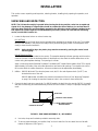
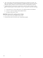
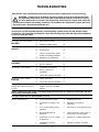
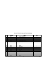
ICE/BEVERAGE DISPENSER
Models DB150--M
DB150--BM
DB150--BCM
Operator’s Manual
Illustration in this space
Remove box after placing the
illustration
Part No. 91773
October, 1993
Revision A
THIS DOCUMENT CONTAINS IMPORTANT INFORMATION
This Manual must be read and understood before installing or operating this equipment
Ó IMI CORNELIUS INC; 1993
PRINTED IN U.S.A
TABLE OF CONTENTS
Page
LIST OF FIGURES
LIST OF TABLES
i
Doc P/N Here
TABLE OF CONTENTS (cont’d)
Doc P/N Here
ii
SAFETY INFORMATION
Recognize Safety Information
This is the safety-alert symbol. When you see this
symbol on our machine or in this manual, be alert to
the potentially of personal injury.
Follow recommended precautions and safe operating
practices.
Understand Signal Words
DANGER
A signal word - DANGER, WARNING, OR CAUTION
is used with the safety-alert symbol. DANGER identifies the most serious hazards.
WARNING
Safety signs with signal word DANGER or WARNING
are typically near specific hazards.
General precautions are listed on CAUTION safety
signs. CAUTION also calls attention to safety messages in this manual.
CAUTION
Follow Safety Instructions
Carefully read all safety messages in this manual and on your machine safety signs. Keep safety signs in
good condition. Replace missing or damaged safety signs. Learn how to operate the machine and how to
use the controls properly. Do not let anyone operate the machine without instructions. Keep your machine in
proper working condition. Unauthorized modifications to the machine may impair function and/or safety and
affect the machine life.
CO2 (Carbon Dioxide) Warning
CO2 Displaces Oxygen. Strict Attention must be observed in the prevention of CO2 (carbon dioxide)
gas leaks in the entire CO2 and soft drink system. If a CO2 gas leak is suspected, particularly in a
small area, immediately ventilate the contaminated area before attempting to repair the leak. Personnel exposed to high concentration of CO2 gas will experience tremors which are followed rapidly by
loss of consciousness and suffocation.
Shipping, Storing, Or Relocating Unit
CAUTION: Before shipping, storing, or relocating this Unit, the syrup systems must be sanitized and
all sanitizing solution must be purged from the syrup systems. All water must also be purged from
the plain and carbonated water systems. A freezing ambient temperature will cause residual water
remaining inside the Unit to freeze resulting in damage to internal components of the Unit.
1
91773
THIS PAGE LEFT BLANK INTENTIONALLY
91773
2
SAFETY PRECAUTIONS
Always disconnect power to the dispenser before servicing or cleaning.
Never
Place hands inside of hopper or gate area without disconnecting power to the dispenser. Agitator
rotation occurs automatically when dispenser is energized.
This ice dispenser has been specifically designed to provide protection against personal injury and
eliminates contamination of ice. To insure continued protection and sanitation, observe the following.
Always be sure the removable lid is properly installed to prevent unauthorized access to the hopper
interior and possible contamination of the ice.
Always be sure the upper and lower front panels are securely fastened.
Always keep area around the dispenser clean of ice cubes.
CAUTION: Dispenser cannot be used with crushed or flaked ice.
Use of begged ice which has frozen into large chunks can void warranty. The dispenser
agitator is not designed to be an ice crusher. Use of large chunks of ice which “jam up” inside the
hopper will cause failure of the agitator motor and damage to the hopper. If bagged ice is used, it
must be carefully and completely broken into small, cube-sized pieces before filling into the
dispenser hopper.
1
91773
GENERAL DESCRIPTION
This section gives the Unit description, theory of operation, and design data for
IMPORTANT: To the user of this manual -- This manual is a guide for installing, operating, and maintaining this equipment. Refer to the Table of Contents for page location for detailed information pertaining to questions that arise during installation, operation, service, or maintenance of this equipment.
DESCRIPTION
The REMCORR “DB”series of ice dispensers solve your ice and beverage service needs in the sanitary, space
saving, economical way. Designed to be manually filled with ice from any remote ice making source, these dispensers will dispense cubes (up to 1-1/4?in size), cubelets and hard-chipped or cracked ice, and in addition,
several flavors of post-mix beverages. “B”models contain beverage faucets only and must be supplied with
cold product from any remote cold plate of refrigerated soda factory.
“BC”units include faucets and cold plates and are designed to be supplied direct from syrup tanks and carbonator, with no additional cooling required.
IMPORTANT: for dispensing Scotsman “pellet” style ice (Model MH750 Ice Makers), RemcorR part
number 02234 Ice Diverter kit must be installed on the dispenser. (See INSTALLATION INSTRUCTION
on page 5).
Table 1. Specifications
Model:
Ice Storage:
Maximum Number of Faucets Available:
Built-in Cold Plate
Electrical:
Dimensions:
Model:
Ice Storage
Maximum Number of Faucets Available
Built-in Cold Plate
Electrical:
Dimensions:
Model:
Ice Storage
Maximum Number of Faucets Available
Built-in Cold Plate
Electrical:
Dimensions:
91773
DB150S-M
150 lbs.
Not Available
No
120/1/60
22?W x 32-1/2? D x 36-1/2? H
DB150S-BM
150 lbs.
6
No
120/1/60
22?W x 32-1/2? D x 36-1/2? H
DB150S-BCM
150 lbs.
6
Yes
120/1/60
22?W x 32-1/2? D x 36-1/2? H
2
INSTALLATION
This section covers unpacking and inspection, selecting location, installing Unit, preparing for operation, and
operation.
UNPACKING AND INSPECTION
NOTE: The Unit was thoroughly inspected before leaving the factory and the carrier has accepted and
signed for it. Any damage or irregularities should be noted at the time of delivery (or not later than 15
days from date of delivery) and immediately reported to the delivering carrier. Request a written inspection report from Claims Inspector to substantiate any necessary claim. File claim with the delivering
carrier, not with IMI Cornelius Inc.
1. Locate the dispenser indoors on a level counter top.
LEG OPTION
Unpack the 4 legs and install them into the threaded holes provided in the bottom of the unit. The installer
must provide flexibility in the product and utility lines to permit shifting the position of the dispenser sufficiently to clean the area beneath it.
NOTE:
before installing legs, the plastic plugs must be removed by pushing the center in and
removing plug.
COUNTER MOUNTING
The ice dispenser must be sealed to the counter. The template drawing indicates openings which must be
cut in the counter. Locate the desired position for the dispenser, then mark the outline dimensions on the
counter using the template drawings. Cut openings in counter.
Apply a continuous bead of National Sanitation Foundation (NSF) listed silastic sealant (Dow 732 or equal)
approximately 1/4?inside of the unit outline dimensions and around all openings. Then position the unit on
the counter within the outline dimensions. All excess sealant must be wiped away immediately.
2. Utilities: DB150S-M Model: The electrical power cord, air/CO2 line and dispenser drain (3/4 FPT) are
located at the rear of the unit.
DB150S-BM Models: All utilities are routed out the bottom of the unit. See “Mounting Template”
on page 6 for locating the required clearance holes in the counter for these utility lines.
3. Connect the drain tube to an open drain. For DB150 models, the drain line size must be 3/4?IPS (or equal)
and must continuously pitch downward away from the unit and contain no “traps”or improper drainage will
result.
DRAIN LINE
STAINLESS STEEL ELBOW
DISPENSER BOTTOM
DRAIN TUBING PROVIDED
WITH DISPENSER
FIGURE 1. SINK DRAIN ASSEMBLY --B, --BC MODELS
A.
Use tube, clamp and insulation provided to assembly drain.
B.
To assure proper drainage, do not allow “trap”to form in drain line. Be sure drain line runs flat with
bottom of dispenser (See Figure 1)
3
91773
4. “--BM”, “--BCM”models: connect the beverage system product lines as indicated in “B”and “BC”units,
pages 7 and 8 respectively. This work should be done by a qualified serviceman. Note that the hoses are
marked with number (1 through 6) for syrup connections and “CW”for carbonated water connections.
5. Regulated and filtered CO2 gas pressure or compressed air is required to operate the dispenser portion
control ice dispensing system. Proceed as follows to connect CO2 gas pressure source line to the dispenser.
A.
Connect and route CO2 line from outlet side of the CO2 regulator assembly up to the dispenser.
B.
Connect CO2 source line to dispenser inlet line labeled “AIR/CO2”.
C.
Set regulator outlet pressure to 50 psi.
IMPORTANT: maximum air/CO2 operating pressure is 50 psig.
6. Clean the hopper interior (see CLEANING INSTRUCTIONS).
7. Connect the power cord to a 120 volt, 60 cycle, 3-wire grounded receptacle.
91773
4
KIT 02234 INSTALLATION INSTRUCTIONS
NOTE:
For dispensing Scotsman NM650 “nugget” style ice and Wilshire MCC500 and MCC700
compressed ice cubes.
1. Disconnect power to dispenser.
2. Remove upper front panel from dispenser.
3. Remove ice chute and discard gate restrictor.
4. Reinstall front panel and energize unit.
5
91773
GATE MOUNTING PLATE
STORAGE HOPPER
ICE DIVERTER
GASKET
APPLY RTV TO THIS SURFACE TO SEAL TO HOPPER
GATE MOUNTING PLATE
ICE CHUTE
FLANGE EXTENDS INTO
STORAGE HOPPER THROUGH
GATE OPENING
10-32 WASHER
10-32 NUT
FIGURE 2. ICE DIVERTER
91773
6
1?
4-1/2?
OPENING
18-3/4? AVAILABLE
FOR HOSE OUTLETS
3-15/16?
14?
OPENING
*1-1/8?
OPENING IN CABINET
BOTTOM FOR DRAIN &
BEVERAGE HOSES
16-1/4?
OPTIONAL LOCATION FOR
COUNTER TOP CUT-OUT
31-1/8
5/16-18 THREADED
HOLE TO SECURE
UNIT TO COUNTER
(4--PLCS)
FRONT OF UNIT
1-1/8?
*19-3/4?
TOP VIEW
(COUNTER CUTOUT)
FIGURE 3. MOUNTING TEMPLATE
7
91773
91773
8
CW
CW
6
5
4
3
2
1
REMCOR “--B” ICE/EVERAGE DISPENSER
ITREMS OUTSIDE OF BROKEN LINES NOT
INCLUDED WITH UNIT.
FAUCETS
5-15
PSIG
S2
S3
S4
S5
FIGURE 4. FLOW DIAGRAM “--B” MODELS
S6
15 -- 50 PSIG
CARBONATOR
FAUCETS 3 AND 4 CAN BE CONVERTED
TO NON-CARBONATED WATER
COLD PLATE OR
REFRIGERATED
ICE BANK
S1
OPTIONSL FOR DIET OR ROOT BEER
FILTER
WATER
SUPPLY
60 -- 100 PSIG
OPTIONAL
PRESSURE REGULATOR
NOTE:
FOR REFERENCE ONLY
NOT FOR CONTRUCTION
CO2 TANK
REGULATORS
9
91773
CW
CW
COLD PLATE
6
5
4
3
2
1
REMCOR “--BC” ICE/EVERAGE DISPENSER
ITREMS OUTSIDE OF BROKEN LINES NOT
INCLUDED WITH UNIT.
FAUCETS 3 AND 4 CAN BE CONVERTED
TO NON-CARBONATED WATER
FAUCETS
5-15
PSIG
S1
S3
S4
CARBONATOR
S5
S6
15 -- 50 PSIG
FILTER
WATER
SUPPLY
NOTE:
FOR REFERENCE ONLY
NOT FOR CONTRUCTION
CO2 TANK
REGULATORS
60 -- 100 PSIG
OPTIONAL
PRESSURE REGULATOR
FIGURE 5. FLOW DIAGRAM MODEL “--BC”
S2
OPTIONSL FOR DIET OR ROOT BEER
91773
10
MAINTENANCE
The following dispenser maintenance should be performed at the intervals indicated.
DAILY (or as required)
Remove foreign material from vending area sink to prevent drain blockage.
WEEKLY (or as required)
Clean vending area. Check for proper water drainage from the vending area sink.
MONTHLY
Clean and sanitize the hopper interior (see CLEANING INSTRUCTIONS).
START-UP AND OPERATING INSTRUCTIONS
Fill the hopper with ice and replace the lid. Allow 10 to 15 minutes for the cold plate to cool down. Repeat this
procedure whenever the dispenser has been standing overnight or other long periods without ice use. On “B”
and “BC”models, start up the beverage system and adjust faucets to the proper brix. Contact your local syrup
distributor for complete information on the beverage system.
To dispense ice, hold cup under ice chute and press the appropriate size button on the ice portion control located above the ice chute. An extra ice portion may be obtained by pressing the increase key (Y ) before pressing the size button. Pushing the button/lever on any faucet will provide beverage of the appropriate flavor.
NOTE:
Use caution to avoid spilling ice when filling dispenser. Clean up immediately any spilled ice
from filling or operating the unit. To prevent contamination of ice, the lid must be installed on
the unit at all times.
FIGURE 6. ICE PORTIONING
ICE PORTIONING SYSTEM OPERATION
The ice portioning system consists of three main components:
1. Ice portion control
2. Ice gate mechanism
3. Solenoid operated air valve
When a size button on the ice portion control is pressed, the control applies a voltage to the air valve for a brief
period of time. The air cylinder attached to the ice gate will then open the ice gate for a short time, allowing ice
to be dispensed from the ice chute.
11
91773
The ice portion control has five modes to allow adjustment of the ice portions and for normal operation they are
as follows:
INDICATOR STATUS
MODE
Normal operation
Green
Cleaning mode
Red/Amber flashing
Normal ice portion adjustment
Amber
Extra ice portion adjustment
Red
Agitation refill time adjustment
Amber flashing
The control will return to Normal Operation Mode (green indicator) automatically if a button has not been operated for a period of one minute whenever one of the three adjustment modes have been accessed.
NORMAL OPERATION
To dispense ice, hold a cup directly under the ice chute, then press the appropriate size button on the ice portion control. To obtain a full cup of ice, press the increase button followed by the appropriate size button. The ice
portion control will not dispense ice and will display a flashing green indicator light if sufficient ice is not available
in the ice chute to dispense the selected size. The indicator light will return to solid green and ice dispensing will
resume after the ice chute has been refilled.
The amount of ice dispensed for each size is changed in the Normal and Extra Ice Adjustment Modes. To access the adjustment modes, press the decrease and increase buttons at the same time. The control will advance to the next mode in the sequence as shown in the table above and the indicator light will change to identify which mode is currently active.
CLEAN MODE
Access this mode when cleaning the ice chute. Refer to Cleaning Instructions on page 12.
NORMAL ICE PORTION ADJUSTMENT
From the Normal Operation Mode (green indicator), press both the decrease and increase buttons at the same
time twice. The amber indicator verifies that the normal portion adjustment mode has been accessed.
To change the amount of ice dispensed, press and hold down the size button for the desired size to be
changed. While holding the size button, press the decrease or increase button to decrease/increase the ice portion size. The amber indicator turns off briefly each time the decrease or increase button is pressed. When the
minimum ice portion adjustment has been reached, the indicator will flash at a slow rate; at the maximum adjustment, the indicator will flash at a fast rate. After releasing the size button, the indicator light will flash green
for five seconds. During this time period, a sample can be obtained to check the portion size by pressing the
size key. The indicator light will return to amber (normal portion adjustment mode) after the sample is d
The indicator light will flash red after dispensing a sample, if an open circuit exists in the ice gate cylinder switch
wiring to the ice portion control of if an ice gate binding condition occurred during the sample. The indicator light
will display solid red briefly after a sample is dispensed if the ice gate cylinder switch was shorted.
To return to Normal Operation, press the decrease and increase buttons at the same time, twice.
EXTRA ICE PORTION ADJUSTMENT
The adjustment of Extra Ice Portions is accomplished in the same manner as Normal Ice Portions, except the
indicator light displays red. To access this mode, press both the decrease and increase buttons simultaneously
three time from the Normal Operation Mode (green indicator). The indicator will display red.
AGITATION REFILL TIME ADJUSTMENT
To adjust the amount of ice chute refill agitation, begin by accessing the Extra Ice Portion Adjustment Mode (red
indicator). Next, press and hold for the decrease and increase buttons for three seconds until the indicator
flashes amber. The indicator will flash up to four times; one flash corresponds to the minimum amount of refill
agitation and four flashes corresponds to the maximum amount of refill agitation. Change the amount of refill
agitation buy pressing one of the four size buttons -- -- the small button representing the minimum amount of
refill agitation. Increase the amount of refill agitation if the ice chute does not refill properly after dispensing ice.
To return to Normal Operation Mode, press the decrease and increase buttons at the same time.
12
91773
CLEANING INSTRUCTIONS
WARNING: DISCONNECT ALL POWER BEFORE CLEANING. Do not use metal scrapers,
sharp objects or abrasives on the ice storage hopper, top cover and the agitator disk, as
damage may result. Do not use solvents or other cleaning agents, as they may attack the
plastic material.
DISPENSER (All Models)
1. Clean the ice storage hopper at least once a month.
2. Remove center screw and washer on agitator disk and lift off the agitator and the agitator disk assembly.
Wash and rinse them thoroughly.
3. Wash down the inside of the hopper and top cover with a mild detergent solution and rinse thoroughly to
remove all traces of detergent.
4. Replace the agitator.
5. Sanitize the inside of the hopper and agitator with a solution of 1 ounce of household bleach in 2 gallons of
water (200 PPM).
6. Replace the agitator disk. Sanitize as described in Step 5. Be sure center screw and washer are replaced
and screw is tight.
7. Clean and sanitize the ice chute as described below:
A.
Enter the Clean Mode of the ice portion control by pressing the decrease and increase buttons at the
same time. The indicator light will alternately display red/amber.
B.
To empty the ice from the ice chute, press any of the size buttons. The ice gate will then open to allow
the ice chute to empty. The ice gate will automatically close after the ice chute as been emptied.
C.
Remove the 2 thumbscrews attaching the upper service panel and remove the panel.
D.
Remove the 2 thumbscrews attaching the ice chute strap and remove the strap
E.
Remove the 4 thumbscrews that secure the ice tube to the ice hopper. Rmove the ice chute and gate
cover. Power to the ice portion control and beverage valves will be interrupted while the ice chute is
removed.
F.
Wash ice chute, gate slide and gate cover in detergent soap solution. Then rinse thoroughly with plain
water. Sanitize as described in Step 5.
G.
Replace components removed for cleaning in reverse order of removal.
H.
Portion control will automatically return to Normal Operating Mode (green Indicator) after the ice chute
is replaced.
COLD PLATE (--BC Models)
1. Carefully remove screws holding beverage faucet panel and bring forward.
2. Slide the cold plate cover back. (Remove shipping tape and discard.)
3. Remove any debris from the drain trough and spring. Check that drain hole is not clogged.
4. Wash down the inside of the cold plate, tray and cover with a mild detergent solution and rinse. A small,
long-handled brush will be found helpful in reaching the corners.
13
91773
5. Slide the cover forward, taking care that it is securely positioned on the cold plate.
6. Replace beverage faucet panel.
BEVERAGE SYSTEM (--B, --BC Models)
1. Remove faucet spouts, wash in mild detergent, rinse and replace.
2. Disconnect electrical power to the carbonator. Shut off the water supply and close the CO2 regulator to the
carbonator.
3. Disconnect the syrup tanks from the system.
4. Energize the beverage faucets to purge the remaining soda water in the system.
5. Use a clean 5 gallon tank for each of the following:
A.
Cleaning Tank -- Fill with hot (120_- 140_) potable water.
B.
Sanitation Tank - Fill with a chlorine sanitizing solution in the strength of 1 ounce of household bleach
(sodium hypochlorite) to 2 gallons of cold (ambient) potable water (200 PPM).
6. Repeat the following procedure on each of the units syrup product lines.
A.
Connect the cleaning tank to the syrup line to be sanitized and to the CO2 system.
B.
Energize the beverage faucet until the liquid dispensed is free of any syrup.
C.
Disconnect the cleaning tank and hook-up the sanitizing tank to the syrup line and CO2 systems.
D.
Energize the beverage faucet until the chlorine sanitizing solution is dispensed through the faucet.
Flush at least 2 cups of liquid to insure that the sanitizing solution has filled the entire length of the
syrup line. Allow sanitizer to remain in lines for 20 minutes.
E.
Disconnect the sanitizing tank. Hook-up the product tank to the syrup line and to the CO2 system.
F.
Energize the faucet to flush the sanitizing solution from the syrup line and faucet. Continue draw on
the faucet until only syrup is dispensed.
7. Repeat Step 2 in reverse order to turn on the carbonator. Dispense at least 1 cup of beverage from each
faucet. Check taste. Continue to flush, if needed, to obtain a satisfactory tasting drink.
91773
14
TROUBLESHOOTING
IMPORTANT: Only qualified personnel should service internal components or electrical wiring.
WARNING: If repairs are to be made to a product system, remove quick disconnects from
the applicable product tank, then relieve the system pressure before proceeding. If repairs
are to be made to the CO2 system, stop dispensing, shut off the CO2 supply, then relieve the
system pressure before proceeding. If repairs are to be made to the refrigeration system, make sure
electrical power is disconnected from the unit.
Should your unit fail to operate properly, check that there is power to the unit and that the hopper
contains ice. If the unit does not dispense, check the following chart under the appropriate symptoms
to aid in locating the defect.
Trouble
Probable Cause
Remedy
BLOWN FUSE OR CIRCUIT
BREAKER.
A.
Short circuit in wiring.
A.
B.
Defective agitator motor.
B.
SLUSHY ICE. WATER IN
HOPPER.
A.
Blocked drain.
A.
B.
Unit not level.
B.
C.
Poor ice quality due to water
quality or icemaker problems.
C.
D.
Improper use of flaked ice.
D.
BEVERAGES DO NOT
DISPENSE.
A.
No 24 volt power to faucets.
A.
B.
No CO2 pressure.
B.
BEVERAGE TOO SWEET.
A.
Carbonator not working.
A.
B.
No CO2 pressure in
carbonator.
B.
C.
Faucet brix requires adjusting.
C.
BEVERAGE NOT SWEET
ENOUGH.
A.
Empty syrup tank.
A.
B.
Faucet brix requires adjusting.
B.
BEVERAGE NOT COLD
(UNITS WITH BUILT-IN COLD
PLATE)
A.
Unit standing with no ice in
hopper - no ice in cold plate
cabinet.
A.
NOTE: Contact your local syrup or beverage equipment distributor for additional information and troubleshooting of beverage system.
TROUBLESHOOTING ICE DISPENSING SYSTEM
NO ICE DISPENSED.
A.
Ice bin cover not in place.
A.
Install ice bin cover.
B.
Insufficient ice supply in ice
bin.
B.
Replenish ice supply as
instructed.
C.
Ice in ice bin bridged (stuck
together).
C.
Gently tap on ice to break it loose.
D.
No electrical power to
dispenser.
D.
Plug in dispenser power cord, or
check fuse or circuit breaker.
E.
Insufficient or no CO2 supply
to dispenser.
E.
Restore CO2 supply to dispenser.
F.
Inoperative ice portion
controller.
F.
Replace ice portion controller.
15
91773
Trouble
91773
Probable Cause
Remedy
G.
Inoperative ice agitator motor.
G.
Replace ice agitator motor.
H.
Inoperative gate cylinder.
H.
Replace gate cylinder.
I.
Inoperative gate solenoid.
I.
Replace gate solenoid.
J.
Defective motor capacitor.
J.
Replace capacitor.
K.
Ice gate not aligned to ice
chute.
K.
Check alignment of ice gate to
slot in ice chute.
L.
Agitate relay wiring incorrect.
L.
Red wire should be connected to
“t”terminal of relay coil.
16
FIGURE 7. ICE/SOFT DRINK POST-MIX DISPENSER
Item
No.
Part No.
Name
Qty.
115
52087
Gasket, Cold Plate Drain
1
116
52089
Ice Bin Cover
1
117
27559
Cup Lid Cover
1
118
27884
Service Panel
1
119
32839
Module Ice Portion Control
1
120
31934
Beverage Valve Power Switch
1
121
31205
Light Indicator, 120 VAC
1
121
32830
Light Indicator, 220 VAC
1
122
70861
Grill
1
123
70478
Clip
4
124
70055
Nut Clip
2
125
27882
Splash Panel
1
126
52064
Drip Tray
1
127
27543
Drip Tray Cabinet Extension
1
128
10145
Mounting Pin, Drip Tray
2
129
51455
Rear, Panel
1
130
70449
Screw
2
131
70450
Washer
2
132
70451
Nut
2
133
70075
Nut
2
134
22139
Bracket, Light Indicator
1
135
70171
Screw
6
17
91773
IMI CORNELIUS INC.
ONE CORNELIUS PLACE
ANOKA, MN. 55303--6234
TELEPHONE (800) 238--3600
FACSIMILE (612) 422--3232
TECH SVC 1-800-535-4240
WARRANTY
IMI Cornelius Inc. and Remcor Products Company warrants that all equipment and parts are free from defects
in material and workmanship under normal use and service. For a copy of the warranty applicable to your
Cornelius and or Remcor product, in your country, please write, fax or telephone the IMI Cornelius office nearest you. Please provide the equipment model number, serial number and the date of purchase.
IMI Cornelius Offices
AUSTRALIA D P.O. 210, D RIVERWOOD, D NSW 2210, AUSTRALIA D (61) 2 533 3122 D FAX (61) 2 534 2166
AUSTRIA D AM LANGEN FELDE 32 D A-1222 D VIENNA, AUSTRIA D (43) 1 233 520 D FAX (43) 1-2335-2930
BELGIUM D BOSKAPELLEI 122 D B-2930 BRAASCHAAT, BELGIUM D (32) 3 664 0552 D FAX (32) 3 665 2307
BRAZIL D RUA ITAOCARA 97 D TOMAS COELHO D RIO DE JANEIRO, BRAZIL D (55) 21 591 7150 D FAX (55) 21 593 1829
ENGLAND D TYTHING ROAD ALCESTER D WARWICKSHIRE, B49 6 EU, ENGLAND D (44) 789 763 101 D FAX (44) 789 763 644
FRANCE D 71 ROUTE DE ST. DENIS D F-95170 DEUIL LA BARRE D PARIS, FRANCE D (33) 1 34 28 6200 D FAX (33) 1 34 28 6201
GERMANY D CARL LEVERKUS STRASSE 15 D D-4018 LANGENFELD, GERMANY D (49) 2173 7930 D FAX (49) 2173 77 438
GREECE D 488 MESSOGION AVENUE D AGIA PARASKEVI D 153 42 D ATHENS, GREECE D (30) 1 600 1073 D FAX (30) 1 601 2491
HONG KONG D 1104 TAIKOTSUI CENTRE D 11-15 KOK CHEUNG ST D TAIKOKTSUE, HONG KONG D (852) 789 9882 D FAX (852) 391 6222
ITALY D VIA PELLIZZARI 11 D 1-20059 D VIMARCATE, ITALY D (39) 39 608 0817 D FAX (39) 39 608 0814
NEW ZEALAND D 20 LANSFORD CRES. D P.O. BOX 19-044 AVONDALE D AUCKLAND 7, NEW ZEALAND D (64) 9 8200 357 D FAX (64) 9 8200 361
SINGAPORE D 16 TUAS STREET D SINGAPORE 2263 D (65) 862 5542 D FAX (65) 862 5604
SPAIN D POLIGONO INDUSTRAIL D RIERA DEL FONOLLAR D E-08830 SANT BOI DE LLOBREGAT D BARCELONA, SPAIN D (34) 3 640 2839 D FAX (34) 3 654 3379
USA D ONE CORNELIUS PLACE D ANOKA, MINNESOTA D (612) 421-6120 D FAX (612) 422-3255
91773
18
IMI CORNELIUS INC.
Corporate Headquarters:
One Cornelius Place
Anoka, Minnesota 55303-6234
Telephone (800) 238-3600
Facsimile (612) 422-3246
Manual number
19


![Service Manual VA13 Carbonator [ 002818 ]](http://vs1.manualzilla.com/store/data/006013608_1-0f8f87056a0ab013b1dd01dac3912d47-150x150.png)