1
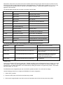
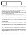
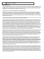
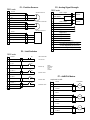
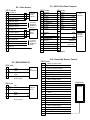
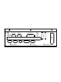
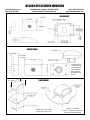
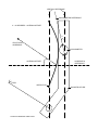
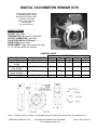
RC3000/RC3050 INTERFACE SPECIFICATIONS
Research Concepts, Inc.
Shawnee, KS 66218-9680 USA
phone: (913) 422-0210
fax: (913) 422-0211
www.researchconcepts.com
email: [email protected]
Overview
The RC3000 Satellite Locator and RC3050 3-Axis Jog Controller are antenna controllers designed for use with elevation over
azimuth antennas on mobile satellite uplink vehicles (also referred to as satellite news vehicles - SNV's). The product has
also been adapted for use on flyaway systems. These microprocessor based controllers are housed in 2U rack enclosures
and interface directly with the antenna’s position sensors, limit switches and motors. The predecessor of these controllers
was the popular RC8097 Satellite Locator. This document describes the interface of the RC3000 and RC3050 controllers to
an antenna mount.
The RC3050 features a 2x16 liquid crystal display (LCD) and an 8 key keypad. The RC3050 can be supplied with an optional
hand-held remote control, (option RC3000HRC). The other option available for the RC3050 is auto-deploy and auto-stow
(option RC3050ASD). The auto deploy feature of the RC3050 allows the user to initiate an auto move that will raise the
antenna from the stow position to the vertical position. The auto stow feature automatically places the antenna in the stow
configuration.
The RC3000 calculates the antenna pointing solution given the vehicle latitude/longitude, vehicle heading, and satellite
longitude. (The pointing solution is the azimuth and elevation angles required to align the antenna with the desired satellite).
Once a pointing solution is available the controller can automatically position the antenna at the calculated azimuth and
elevation position. If the received signal (L band) or an analog voltage proportional to received signal strength is available the
controller will perform a search for the satellite. The RC3000 can obtain the vehicle heading from an optional flux gate
compass (designated RC3000FG) and the vehicle latitude and longitude from an optional GPS navigation receiver
(designated RC3000GPS). If the system does not include the optional flux gate and/or GPS sensors the user can manually
enter this data into the controller. The controller also allows the user to store a number of preset vehicle locations and
satellite longitude values. The RC3000CRC option adds support for RS-232 or RS-422 based serial communications using
the SA Bus protocol. The RC3000TRK option allows the RC3000 antenna controller to track inclined orbit satellites via step
track and memory track algorithms (the antenna must be fitted with azimuth and elevation type pulse position encoders for
inclined oribt tracking). The RC3000 also supports the RC3000HRC hand-held remote control.
Controller Types
The RC3000/RC3050 are currently available in two versions. Models with the ‘A’ suffix are designed for use with antennas
powered by low voltage (12 to 36 volts), high current (up to 12 amps) azimuth, elevation, and polarization DC motors. Models
with the ‘B’ suffix are designed for use with 90 volt (3/4 horsepower max) or 180 volt (1 ½ horsepower max) DC azimuth and
elevation motors (1 horsepower max) and 12 volt DC polarization control motors (400 ma max).
Schematics
Schematics that describe the controller’s motor, limit switch, position sensor, and accessory connections are included in the
appendix of this document.
Physical Characteristics
The RC3000 is designed for rack mounting. The dimensions are 19" x 3.5" x 17.5" (width x height x depth). The weight of
the RC3000A is 19 lbs. The RC3000B weighs 13lbs. The liquid crystal display (LCD) used with the unit is designed for
viewing from a 6 o'clock position. This means that the controller should be mounted above the operator’s eye level. An LCD
module optimized for a 12 o'clock viewing is also available.
The RC3000 enclosure is a standard rack mount chassis that occupies two rack units (2U). The controller is attached to the
panel via four (4) 10-32 screws. The distribution of weight within the controller requires that additional supports be provided
on either the back or sides of the controller enclosure. There are mounting points on the back and sides of the unit that can
accept 10-32 screws for securing the controller to these support structures. Note that the mounting points on the back of
the unit can also be used to attach cable strain relief straps. Locations of the additional enclosure mounting points is
detailed in the appendices of this document. The RC3000 must be supported from the rear.
Caution: RCI’s warranty does not cover damage to the controller due to inadequate support of the controller’s enclosure.
Cabling and Connectors
The only cables supplied with the unit are the AC line cord and the cables for the optional electronic compass and the GPS
receiver. All other cables must be supplied by the customer. A kit is available that contains all mating connectors. The kit
part number is FP-RC3K-CN-SET.
Note that the cable service loop at the back of the controller should be long enough to allow the unit to be pulled out of its
mounting rack with the cabling attached to perform internal adjustments. Also note that the controller’s J1, J3, J6, J7, and
J10 connectors are identical to those on the back of the RC8097 controller. A back panel diagram is included in the
appendix of this document.
The following table describes the connectors on the back of the RC3000.
Designation
Type
Function
J1
DB15 female
az/el/pol position sense
J2
DB15 female
AGC port (RC3000TRK)
J3
DB15 female
limit switches
J4
DB15 male
Pulse sensor input (RC3000TRK)
J5
DB9 female
Serial Comm. Port (RC3000CRC
J6
IEC fused Power Entry
J7
Amphenol 22-20S
az/el/pol motors
J8
Amphenol 126-221
HPA disable and accessories
J9-GPS
DB9 female on dongle
GPS & cable, (RC3000GPS)
J9-FG
DB9 female on dongle
FG Compass & cable (RC3000FG)
J10
DB25 female
Handheld Remote Control (RC3000HRC)
J11
F female
Block LNB signal for auto peak
The following table lists the types of cable employed in the cabling kits produced by RCI.
Cable Type
Cable Configuration
Controller Wiring Harness Circuit
Alpha 2432C
2 x 16 AWG shielded with bare drain wire
Az/El/Pol Motors
Belden 9770
3 x 22 AWG shielded with bare drain wire
Az/Pol Potentiometer and Single Phase pulse
position encoders.
Alpha 2404C
4 x 22 AWG shielded with bare drain wire
Elevation Inclinometer and Limit Switches
(containing two limit switch circuits, i.e.
elevation up and elevation down)
Alpha 1292C
2 x 22 AWG shielded with bare drain wire
Limit Switches
Power Entry
Connector J6 accepts an IEC type AC power plug. RC3000 controllers can be configured at the factory for either 115 or 230
VAC operation. The AC line cord supplied with the controller is appropriate for the controller’s AC power configuration. The
controller’s AC line voltage configuration can be determined by viewing the window on the power entry module. The window
will either display ‘115’ or ‘230’.
The RC3000A can be configured by the user in the field for operation at either 115 or 230 VAC line voltage.
Use the following procedure to re-configure the RC3000A’s AC power configuration …
1.
Switch off the controller.
2.
Remove the IEC power cord from the back panel entry module.
3.
With a small, straight bladed screw driver remove the fuse drawer and the fuse from the power entry module.
4.
Use a pair of needle nose pliers to remove the card (the end of the card is labeled either ‘115’ or ‘230’) from the power
entry module. Rotate the card and insert it into the power entry module so that the desired line voltage is displayed.
5.
Replace the fuse and fuse drawer. Use a slow blow fuse that is appropriate for the line voltage selected: 8 amp for 115
VAC, 4 amps for 230 VAC.
The RC3000B can be configured at the factory for either 115 or 230 VAC operation. The RC3000B’s line voltage setting
cannot modified by the user in the field. The RC3000B uses the same power entry module as the RC3000A. With the
RC3000B, the card inside the power entry module is glued into position. The card indicates the correct voltage but the
voltage cannot be changed by the user in the field. The AC line fuses appropriate for the RC3000B are 12 amp, slow blow for
115 VAC operation and 6 amp, slow blow, for 230 VAC operation.
RC3000A Az/El/Pol Motor Drive
The RC3000A is designed to drive 12 to 36 volt DC azimuth, elevation, and polarization motors. The absolute maximum
allowed motor current is 12 Amps. The RC3000A employs a built-in, solid-state motor controller (model 25A8 from Advanced
Motion Controls – ph: (805 389-1935). The motor drive module supports IR compensation, current limiting, dual speed
operation, and dynamic braking. The drive train is also protected with resettable fuses. Please specify the maximum current
for each axis. For motors with values of L_eff (effective inductance) less than 200 uH, additional inductance must be added
in series with the motors to insure proper operation of the motor drive. These additional inductors can be placed inside the
controller at the factory. When ordering an RC3000A specify L_eff for each motor.
The 3000B is designed to drive 90 volt (3/4 horsepower max) or 180 volt (1.5 horsepower max) DC azimuth and elevation
motors. Ideally, 90 volt DC motors would be specified with 115 VAC input power and 180 volt DC motors with 230 VAC input
power. 180 volt motors cannot be used with 115 VAC input power. The motor drive in the RC3000B is the model KBPB by
KB Electronics (ph: 800 221 6570). This motor drive supports IR compensation, current limiting, dual speed operation, and
dynamic braking.
The polarization drive of the RC3000B is designed to power a 12 volt DC motor which draws less than 400 ma. Motor drive
current is supplied via an MS3102A22-20S type circular connector (designated J7). Shielded cables (shield connected only
at the controller) should be used to interface the motors to the controller. A schematic detailing the motor connections is
included in the appendix.
The following table describes the polarity of the RC3000’s motor drive output signals.
Axis
RC3000 Connector J7
Terminals
Polarity
Azimuth
G, F
For azimuth CW movement, terminal G has the higher potential.
Elevation
H, J
For elevation UP movement, terminal H has the higher potential.
Polarization
A, B
For polarization CW movement, terminal A has the higher potential.
Analog Position Sensors
RC3000/RC3050 controllers are designed to interface to 1K ohm or 5K ohm potentiometer type azimuth and polarization
position sensors and an inclinometer type elevation position sensor.
The RC3000 employs a 10 bit A/D (analog to digital) converter to sense azimuth and polarization positions. Azimuth
(polarization) position resolution can be calculated by dividing the total azimuth (polarization) travel by 983. For example, a
+90° azimuth movement mount has 180° total azimuth travel, 180 degrees B 983 gives 0.18° azimuth resolution. The
azimuth (polarization) position sense potentiometer can be connected either directly to the azimuth (polarization) axis or
driven by gears. If the azimuth potentiometer is attached directly to the azimuth axis pivot point a potentiometer with a
linearity specification of 0.25% (or better) should be employed. Multi-turn potentiometers manufactured by Contelec
(PD22xx series) have performed well in satellite antenna applications. In the US, Contelec potentiometers are distributed by
Novotechnik, ph: 508 485-2244.
Component values in the controller must be tailored to properly match the azimuth and polarization potentiometers to the
mount’s range of azimuth and polarization movement. When ordering an RC3000 or RC3050, please specify the following for
both the azimuth and polarization axis …
Quantity
Units
Example Value
Total range of antenna movement about
the axis.
Degrees
+/- 155 degrees of azimuth movement
Total number of potentiometer turns.
Whole turns and degrees.
10 turns, tolerance: + 0 degrees, - 10 degrees
Ratio of movement about the antenna
axis to potentiometer movement
A ratio, 1:x (x greater than
1)
If 310 degrees of azimuth movement results in 5.6
turns of the azimuth potentiometer the ratio is 1:x,
where x equals (5.6 x 360) / 310 or 1:6.503.
The directional sense of azimuth movement is defined as clockwise (CW) or counter-clockwise (CCW) as viewed by an
observer located above the antenna. On the controller CW movement results in a greater sensed azimuth position.
The directional sense of polarization movement is also defined as CW or CCW as seen by an observer standing behind the
antenna reflector looking ‘through’ the reflector at the satellite. The reference position for the polarization position angle is
vertical polarization for a satellite located at the same longitude as the antenna. In the northern hemisphere, for vertically
polarized satellites to the west of the antenna, the polarization deflection is defined as CW relative to the reference position.
In the northern hemisphere, the polarization angle increases for satellites farther to the west. In some modes of operation
the controller predicts the polarization value required to align the antenna with a given satellite’s horizontal or vertical
polarization position. For this feature to function properly the antenna’s polarization directional sense characteristics (defined
by the polarization motor and position sensor) must be consistent with that of the controller.
The elevation position sense circuit of the RC3000 is designed to interface to the Lucas/Schaevitz AccuStar model 0211
1002-000 or 0211 1102-000 inclinometers (abbreviated data sheet included in the appendix). The inclinometer’s position
reference is marked on the body of the inclinometer. The inclinometer should be mounted such that the body of the
inclinometer is rotated CW (as viewed by an observer looking at the front of the inclinometer) as the antenna’s elevation angle
increases. The inclinometer must also be oriented properly on the antenna mount.
To describe the orientation of the inclinometer, the term ‘elevation offset angle’ needs to be defined. Elevation offset angle is
defined as the antenna’s RF elevation pointing angle (relative to horizontal) when a straight edge oriented vertically across the
face of the antenna reflector (reflector top to bottom) is plumb. The inclinometer should be oriented so that when the antenna
reflector is plumb the reference mark is deflected CCW (from the vertical position) by an amount equal to the 35 degrees
minus the ‘elevation offset angle’. If the inclinometer is attached as described the sensor will operate in its most accurate
region for elevation look angles up to 80 degrees. A paper entitled ‘RC3000 Inclinometer Orientation’ describes the
inclinometer orientation in more detail.
The inclinometer mounting flange allows for some adjustment of the device’s rotational orientation. The mounting position
selected for the inclinometer should allow for adjustment of the inclinometer’s orientation. The inclinometer should be
mounted in a location such that it is protected somewhat from blowing rain.
Connector J1 (DB-15 Female) interfaces the position sensors to the controller. The cables used to interface the controller to
the position sensor should be shielded and the shields should be connected only at the controller end of the cable assembly.
A schematic showing the sensor connections is given in the appendices.
Limit Switches
The RC3000 supports azimuth stow, elevation stow, elevation up, and elevation down limit switches. Azimuth cw/ccw and
polarization cw/ccw limit indications are derived from the azimuth and polarization position sense voltages produced by the
potentiometers. If failsafe limits are required for the azimuth and polarization axis they can be implemented with limit
switches and steering diodes. Contact the factory for more information.
If the azimuth stow limit is not active, the antenna can only be moved in elevation between the down limit and up limit. If the
azimuth stow limit is active, the antenna may be moved in elevation between the elevation stow limit and the elevation up
limit. When the antenna is below the elevation down limit the antenna may not be moved in azimuth or polarization.
The RC3000 optionally supports another limit switch that may be used to indicate polarization stow or antenna deploy
status. The RC3000 does not support polarization limit switches. The user may provide these externally using micro
switches and steering diodes if needed.
The following table describes the limit switch logic …
Limit Switch
Limit Switch Contact Configuration When Antenna Is AT The Limit
Azimuth Stow
Closed
Elevation Stow
Open
Limit Switch
Limit Switch Contact Configuration When Antenna Is AT The Limit
Elevation Up
Open
Elevation Down
Open
Flux Gate Placement
The RC3000 antenna controller can obtain the vehicle’s heading from the optional flux gate compass (RC3000FG). A diagram
of the flux gate is included in the addendum (an unhoused version of the flux gate is also available). The flux gate senses the
direction of the earth's magnetic field. To ensure the greatest accuracy, the flux gate should be mounted in a location that is
free of magnetic fields and away from ferrous metals. Devices which generate magnetic fields include electric motors, high
power microwave amplifiers, microwave circulators and isolators, and power supplies. Note that current flowing through a
conductor generates a magnetic field – the strength of the magnetic field is proportional to the magnitude of the current and
inversely proportional to the distance from the conductor.
Ferrous metals located on the vehicle distort the earth’s magnetic field. For a vehicle, the distortion of the earth’s magnetic
field is generally such that the earth’s magnetic lines of flux tend to align themselves with the vehicle’s long axis. The flux
gate supports calibration routines that can partially compensate for the distortion of the earth’s magnetic field due to ferrous
metal in the vehicle itself and magnetic fields generated by equipment located on the vehicle.
Generally, the best performance is achieved when the flux gate is mounted as high as possible on the vehicle. The RC3000
can support placement of the flux gate on the antenna reflector. When mounted in this manner, the antenna must be raised
to a ‘deploy’ position before the vehicle heading can be obtained.
If the flux gate is to be placed on the roof of the vehicle (as opposed to the back of the antenna reflector), a common wet
compass may be used to help find the best location on the vehicle for the flux gate. To make the measurement it is
generally best if the vehicle is pointed in either a westerly or easterly direction. With the wet compass the user should stand
on the roof of the vehicle and slowly lower the compass down to the proposed flux gate mounting location. If the needle of
the compass experiences deviations as it is lowered to the proposed mounting location it indicates that there are either
external magnetic fields or concentrations of ferrous metals in the vicinity of the proposed flux gate mounting location. The
flux gate should be placed in the location on the roof of the vehicle where the compass experiences the least deviation.
When using the wet compass to determine flux gate placement be sure that all equipment which may be in operation when
the flux gate is used is turned on.
The GPS and Flux Gate Compass interface to the RC3000 via a DB-37 female connector (J9). A DB-37 male to two DB-9
(female) ‘Y’ cable provides an interface to the GPS and Flux Gate interface cables. The flux gate cable should be routed as
far as possible from electrically noisy devices and unshielded cables.
GPS Receiver Placement
The RC3000 can interface with an optional GPS receiver (designated RC3000GPS). The GPS receiver (with built-in antenna)
is housed in a weather proof assembly which must be placed on the roof of the vehicle so that the receiver has a clear view of
the sky when the antenna is stowed. See the addendum of this document for additional GPS mounting information.
The GPS and Flux Gate Compass interface to the RC3000 via a DB-37 female connector (J9). A DB-37 male to two DB-9
(female) ‘Y’ cable provides an interface to the GPS and Flux Gate interface cables. The GPS cable should be routed as far
as possible from electrically noisy devices and unshielded cables.
L Band Input
The RC3000 J11 (F type) connector accepts an L band signal from a satellite block down converter (950 to 1450 MHz, -50 to
–5 dBm). The controller’s L band input circuit provides a DC output voltage that is proportional to the power level of the L
band signal to the controller’s microprocessor. Note that there is a DC block (capacator) in series with the L band input.
The RC3000 can use the L band signal to perform an AutoPeak function (the analog signal strength inputs can also provide
signal strength information for the AutoPeak function). During an AutoPeak the controller performs a search. If a signal is
found the controller peaks the antenna on that signal. For a geostationary satellite the controller performs a line search in
azimuth (the elevation is periodically adjusted to nominal value if the platform is not level). For an inclined orbit satellite, the
controller performs a spiral search.
Analog Signal Strength Input
The RC3000 can accept 2 analog input voltages that are proportional to received signal strength via the J2 connector. Signal
strength information is required for inclined orbit satellite tracking and can optionally provide a source of signal strength
information for the AutoPeak function (see the section on ‘L Band Input’ section above).
The range of analog voltages accepted by the RC3000 is –15 VDC to + 15 VDC. The analog voltages can be generated
either by a beacon receiver or by an AGC (Automatic Gain Control) circuit in a modem or analog receiver. The RC3000 can
accept signal strength inputs of either polarity. In this context positive polarity means that the output voltage increases as
the received satellite signal increases. Negative polarity refers to the case where the output voltage decreases as the
satellite signal increases.
To minimize noise pickup, a shielded cable (with two conductors) such as Alpha 1292C should be used to connect the
source of the signal strength output to the RC3000. Note that the cable shield should be open at either the RC3000 or at the
source of the signal.
Associated with each analog input is a gain and offset potentiometer. These pots level shift and either expand or reduce the
analog input’s dynamic range to match the controller’s A/D conversion range (0 to 5 volts). The offset potentiometers
generate a pair of offset voltages that determines the level shift applied to each of the signal strength inputs. These offset
voltages are available on connector J2 to facilitate adjustment of the gain and offset potentiometers.
Accessory Connector
Connector J8 (9 conductor – Amphenol 126-221 type) provides access to the following circuits …
1.
HPA (High Power Amplifier) Disable is a form C contact arrangement with normally open, common, and normally closed
contacts. When the antenna is below the down elevation limit or the antenna is performing any large-scale auto-moves
such as deploy, locate, or stow, the normally-open and common pins will be connected. For antenna’s that employ
electro-mechanical brakes the HPA disable feature is not enabled. Please contact the factory for details.
2.
Alarm Out is a normally closed relay. These contacts will be closed whenever the controller is powered down or an
alarm condition has been detected. For antenna’s that employ electro-mechanical brakes the Alarm Out feature is
disabled. Please contact the factory for details.
3.
GPS 1 Pulse per Second Output is a TTL square wave output (referenced to the chassis ground connection). This
output is only available if the controller is equipped with a Garmin model 36 GPS receiver. Note that the RC3000GPS
option does not include the Garmin model 36 receiver. Contact the factory for availability of the model 36 receiver.
4.
GPS Instant On Feature – The GPS Instant On feature is realized by powering the GPS receiver while the vehicle is in
motion. This allows the receiver to lock to the GPS satellite signals while it is in transit. The vehicle latitude/longitude
(lat/lon) will be available as soon as the vehicle reaches the uplink location. Without the Instant On feature, after power
up the GPS requires 2 to 4 minutes to determine vehicle lat/lon. With the Instant On feature, the controller applies
vehicle power to the GPS whenever the vehicle ignition system is energized and for approximately 30 minutes after the
vehicle’s ignition system is de-energized.
The GPS Instant On feature requires a direct connection to the vehicle +12V battery, a connection to the +12V vehicle
accessory voltage (+12V on while the vehicle ignition system is on), and a connection to the vehicle’s chassis ground.
When the GPS Instant On feature is active, power is routed to ports 1, 3, and 4 of the navigation sensor connector, J9.
To enable the Instant On feature, diodes D31 and D29 must be installed on the RC3000 feature board.
Support for electro-mechanical brakes on the azimuth and elevation axis can be provided via the J8 connector. This port can
also provide access to an unregulated power supply or other user specified features. Please contact the factory for more
information.
The following table shows the pin connections for J8 on the RC3000.
J8 Pin #
Description
A
HPA Disable, normally-open, 3A @ 30VDC max or 3A @ 250VAC max
B
+12 - +14V Vehicle Battery input (OR +Vunreg. for auxiliary output models, 2A max)
C
Ground, Vehicle chassis ground input.
D
HPA Disable, common, 3A @ 30VDC max or 3A @ 250VAC max
E
HPA Disable, normally-closed, 3A @ 30VDC max or 3A @ 250VAC max
F
Alarm common, 3A @ 30VDC max or 3A @ 250VAC max
G
Alarm normally-closed, 3A @ 30VDC max or 3A @ 250VAC max
H
+12 to +14V Vehicle accessory input (Vunreg. Return for auxiliary output models)
I
1PPS output, TTL compatible
Hand Held Remote
Connector J10 (DB-25 female) provides an interface to the optional hand-held remote control (designated RC3000HRC). The
RC3000HRC option allows an operator to jog the antenna and view antenna limit indications. Antenna position information is
not displayed on the hand-held remote. The remote is housed in a 3” x 6” x 1.75” aluminum chassis and interfaces to the
RC3000 via a 25’ multi-conductor cable (included with the handheld remote).
Pulse Sensors for Inclined Orbit Satellite Tracking Applications
The RC3000 supports interfaces to analog position sensors (azimuth potentiometer, elevation inclinometer, polarization
potentiometer). The analog sensors provide good absolute position accuracy and are used for open loop antenna pointing.
The analog sensors, however, do not provide the resolution needed for inclined orbit satellite tracking. The RC3000TRK
option allows the RC3000 to track inclined orbit satellites using step track and memory track algorithms. For inclined orbit
satellite tracking, the antenna mount must be equipped with azimuth and elevation pulse type position encoders (in addition
to the analog position sensors).
The output of a pulse encoder is a voltage waveform that transitions between two levels (‘high’ and ‘low’) as the encoder shaft
is rotated. There are two types of pulse encoders: single phase and quadrature.
A single phase pulse encoder produces a single channel pulse output. By looking at the output of a single phase encoder
an antenna controller cannot determine which way the shaft of the encoder is being rotated. The controller has to increment
or decrement the position count for that axis by knowing which way the antenna is commanded to move. If pulses occur
when the antenna is not commanded to move (or is not in the coast interval immediately following a move), the controller
does not know whether to increment or decrement the position count. For this reason, single phase pulse encoders can
only be used reliably when they are placed at a point in the antenna drive train that does not experience backdrive. In this
context, backdrive refers to forces applied to the antenna reflector that cause the shaft of the encoder to rotate. In a typical
RC3000 inclined orbit tracking application, single phase Hall effect pulse sensors are placed on the az/el drive motor shafts
and the pulse encoders essentially count motor revolutions. A typical gear ratio for a mobile antenna mount (motor
revolutions to antenna revolutions) is 5000:1 or greater. Backdrive is typically not a problem when the sensors are directly
attached to the antenna az/el drive motors. The Powermation Digital Tachometer is a single phase pulse encoder designed
for use on 56C type motor mounting flanges. The Powermation unit has been used successfully for inclined orbit tracking
with the RC3000. A datasheet describing the Powermation sensor is included with this document.
A quadrature pulse sensor produces two channels of pulse information as the encoder shaft is rotated. One channel is offset
90 degrees from the other when the input shaft of the sensor is turning in a given direction. With a quadrature sensor it is
possible to determine which way the sensor shaft is turning by looking at the phase relationship between the two output
pulse waveforms. This characteristic allows quadrature sensors to be attached directly to the antenna mount’s az/el pivot
points – as the antenna blows around in the wind the outputs from the quadrature pulse encoder are properly accumulated by
the antenna controller. Quadrature pulse encoders are usually equipped with a third channel that produces an index pulse.
The index pulse is active only when the sensor shaft is at a reference position. The index channel can be used by a
controller to initialize the controller’s internal pulse position count.
At the present time the RC3000 does not support quadrature type pulse encoders. The controller can interface to single
phase pulse position encoders whose power supply requirements are compatible with 5.7 volts DC (200 milliamps max).
Note that other pulse position encoder power supply voltages are available, please contact the factory for details). The
RC3000 controller counts both the rising and falling edges of the pulse output waveform (i.e. each pulse provides two position
counts). The position count is decremented for azimuth ccw (elevation down) movement and incremented for azimuth cw
(elevation up) movement. The waveform's high level amplitude should be 4.5 volts or greater and the waveform’s low level
amplitude should be less than 0.5 volts. The waveform's minimum high or low pulse duration should be at least 10
milliseconds. This means that pulses less than 10 milliseconds in duration may not be detected by the antenna controller.
The controller can accumulate a maximum of 65000 pulses about either the azimuth or elevation axis. Note that for single
phase pulse sensors that count motor revolutions (such as the Powermation unit), a one pulse per revolution sensor
characteristic is almost always appropriate.
Shielded cables equipped with a bare drain wire that provides a connection to the shield must be employed to interface the
controller to the position encoders. The drain wire must be connected at the controller to the AZ PULSE SHEILD and EL
PULSE SHIELD terminals provided on the J4 connector. The drain wire and shield must not be allowed to come in contact
with earth ground or the vehicle chassis. Use heatshrink at the sensor to prevent the frayed ends of the shield or drain wire
from making contact with the sensor body or connector. If the drain wire is allowed to come in contact with earth ground a
ground loop will be formed (the controller SHIELD terminals are connected to the vehicle chassis). With a ground loop
current flowing in the earth ground plane or vehicle chassis can flow through the sensor shield and cause stray counts to be
induced in the controller’s pulse input circuits. If the sensor cable is spliced be sure to splice the drain wire and insulate the
connection to prevent a ground loop.
RS232/RS422 Serial Communications
J5 allows for PC remote control of the RC3000. The RC3000 may be internally configured to communicate using either RS232 or RS-422 electrical levels. The communications protocol is derived from the SA Bus standard. Please see the white
paper entitled ‘Computer Control of Satellite Antennas’ for more information on the communications protocol.
Schematics
P1, P2, P3, P4, P5, P7, P9, P10, Back Panel
Addendum
Flux Gate (1 page), AccuStar Clinometer (1 page with dimensions), GPS (1 page), Inclinometer Orientation (1 page),
Powermation Sensor (1 page), RC3000 Rear Chassis Supports (1 page)
P2 - Analog Signal Strength
P1 - Position Sensors
DB15 male
10
AZ Drain
9
AZ +
1
AZ Wiper
2
AZ -
3
POL Drain
11
POL +
4
POL Wiper
12
POL -
7
El Drain
6
El +15
14
El Com
8
El -15
15
El Signal
DB15 male
8
Azimuth Position Pot.
AGC 1 Input
Receiver
7
Polarization Position Pot.
Elevation Inclinometer
AGC Return
15
AGC 2 Input
5
Shield
14
V_Offset 1
10
Offset Return
13
V_Offset 2
1
Digital I/O 0
2
Digital I/O 1
3
Digital I/O 2
4
Digital I/O 3
Receiver
6
+5 VDC (200 mA. max)
9
+24 VDC Unregulated (1 A. max.)
11
-15 VDC Regulated (40 mA. max.)
12
+15 VDC Regulated (40 mA. max.)
P3 - Limit Switches
DB15 male
9
AZ Stow +
7
AZ Stow -
10
EL Up +
14
EL Up -
5
EL Down +
6
EL Down -
11
EL Stow +
13
EL Stow -
2
Pol Stow +
1
Pol Stow -
4
Drain
NC
LIMIT SWITCHES
Azimuth Stow
NO
Elevation Up
NO
Switch
Annotations
are for the
Limit
Condition
Elevation Down
P7 - Az/El/Pol Motors
NO
Elevation Stow
NO
Polarization Stow
Amphenol 22-20P
E
AZ Drain
G
Az Drive
F
Az Return
D
El Drain
H
El Drive
DC MOTORS
AZIM
ELEV
J
El Return
C
Pol Drain
A
Pol Drive
POL
B
Pol Return
P9 - GPS & Flux Gate Compass
P4 - Pulse Sensor
DB37 male
DB15 female
2
AZ Pulse In
1
AZ Pulse Return
10
AZ Pulse Power *
9
AZ Pulse Shield
4
AZ Quad Pulse
3
AZ Quad Return
11
AZ Quad Power *
7
EL Pulse In
8
EL Pulse Return
14
EL Pulse Power *
15
EL Pulse Shield
5
EL Quad Pulse
6
EL Quad Return
13
EL Quad Power *
12
Alarm In
Azimuth
Pulse
Sensor
For Future
Support of
Quadrature
Sensor
Elevation
Pulse
Sensor
For Future
Support of
Quadrature
Sensor
DB9 male
1
20
2
21
3
22
4
23
5
P1-Vaux
N/C
P1-RX1
P1-TX2
P1-TX1
P1-GND (N/C)
P1-Vpwr
P1-RX2
P1-GND
1
6
2
7
3
8
4
9
5
24
6
25
7
26
8
27
9
28
P2-GND
N/C
P2-Vpwr
P2-GND (N/C)
P2-TX1
N/C
P2-RX1
N/C
P2-Vaux
5
9
4
8
3
7
2
6
1
Yellow
Gray
White
Green
Blue
N/C
Red
Purple
Black
GPS
Receiver
TXD1
RXD1
Vin
GND
GND
Fluxgate
Compass
(Housed)
Vin
GND
RS232 IN
RS232 OUT
DB9 male
P10 - Hand Held Remote Control
DB25 male
P5 - RS232/RS422 I/O
1
2
DB9 male
2
RXD
3
TXD
5
GND
PC
Serial Port
RS-232 Wiring
DB9 male
3
TXD
9
TXD/
4
RXD
6
RXD/
RS-422 Wiring
RS-422
BUS
3
14
4
17
5
15
6
19
7
20
8
21
9
22
16
23
11
24
12
25
13
Black w/ White Stripe
Red w/ Black Stripe
Orange w/ Black Stripe
Black w/ Red Stripe
Orange w/ Red Stripe
Blue w/ Red Stripe
Red w/ White Stripe
Blue w/ White Stripe
Green w/ White Stripe
Green
Orange
Red
Blue w/ Black Stripe
White
Green w/ Black Stripe
Blue
White w/ Red Stripe
Black w/ Red & White Stripe
Green w/ Black & White Stripe
Red w/ Green Stripe
White w/ Red & Black Stripe
Orange w/ Green Stripe
Red w/ White & Black Stripe
(Optional)
Remote
Accessories
RF Auto F
Peak
O
S
2
G
N
2
O
S
1
Signal Strength
Pulse Sensors
Navigation Sensors
DB-15 F
DB-15 M
DB-37 F
J2 - AGC
J4 - Pulses
J9 - Navigation
G
N
1
J1 - Sensors
J3 - Limits
J5 - Comms.
J10 - Handheld
J12 - Waveguide
DB-15 F
DB-15 F
DB-9 F
DB-25 F
DB-15 F
Drive Sensor
Limit Switches
PC Remote
Handheld Remote
Wavguide Switch
10-32 threaded insert
J8 - Acc.
10-32 threaded insert
J7
Motor
Drive
J6
Power
Entry
Fuse
Motors - J7
10-32 threaded insert
RC3000 FLUXGATE COMPASS
Research Concepts, Inc.
Fax: (913) 422-0211
•
•
•
•
•
5420 Martindale, Shawnee, KS 66218-9680
e-mail:[email protected]
Phone: (913) 422-0210
www.researchconcepts.com
This sensor will operate through tilt (pitch & roll) ranges of +16o.
Cable 25’, 1/4” diameter, terminated with a D9 male connector
A 1.25” x .625” opening is required for the connector to pass through a
panel.
An unhoused model is also available.
Environmental Specifications
• Operating Temperature: -40oC to +65oC
• Storage Temperature: -57oC to +71oC
What you need to know to order.
AccuStar
Electronic Clinometer
Model Number
Description
0211 1002-000
0211 1102-000
Analog
Vertical Flange
Horizontal Flange
Lucas Control Systems
1000 Lucas Way
Hampton, VA 23666
Phone: (757) 766-1500
Fax: (757) 766-4458
Internet: www.schaevitz
Analog Output
Features
√
√
Internally regulated
Bipolar input/output
The Analog clinometer is a signal conditioned sensor which has been
designed for dc voltage, bipolar operation. The clinometer requires a bipolar
supply of ±8 to ±15 VDC and delivers an output of ±3.6 VDC. This device is
internally regulated for various applications. The output scale is fixed at a
nominal 60mV per degree not dependent on the supply voltage. The Analog
clinometer has full EMI and ESD suppression circuitry on every line.
Analog Electrical Specifications
Voltage
Voltage Supply
Nominal
Range (regulated)
Current
Scale Factor
Load Resistance (min.)
Level Output (0°)
±12 VDC
±8 to ±15 VDC
5 mA/supply
60 mV/degree ±10%
10 k0hms
0 VDC
Electrical Connections
Wire Source
Black
Power ground
Red
+8 to +15 VDC
Gray
-8 to -15 VDC
Blue
Signal output
(reference to power ground)
RC3000 GPS RECEIVER MOUNTING
Research Concepts, Inc.
Fax: (913) 422-0211
5420 Martindale, Shawnee, KS 66218-9680
e-mail:[email protected]
Phone: (913) 422-0210
www.researchconcepts.com
BASIC MOUNT
MARINE MOUNT
A marine mount is a
1” diameter rod with
14 TPI (Thread Per
Inch), non tapered.
Will work with 3/4”
NPT (National Pipe
Thread).
3.80”
2.25”
FLANGE MOUNT
2.86”
1.5
7”
0”
2.5
Operating Temp. -30oC to +85oC
Storage Temp. -40oC to +90oC
2.50”
Cables 25’, 1/4” diameter
A 1.25” x .625” opening is required for the
connector to pass through a panel.
VERTICAL REFERENCE
INCLINOMETER REFERENCE
X = 35 DEGREES - ANTENNA OFFSET
X
ELECTRICAL
BORESIGHT
INCLINOMETER
ANTENNA OFFSET
HORIZONTAL
REFERENCE
FEED
REFLECTOR
BACKSTRUCTURE
RC3000 INCLINOMETER ORIENTATION
DIGITAL TACHOMETER SENSOR KITS
POWER/MATION
W238 N1690 Rockwood Drive
Waukesha, WI 53188
Phone: (414) 523-0600
800-242-2060
Fax: (414) 523-0611
SPECIFICATIONS
INPUT: 5-16 VDC
OUTPUT: NPN, 20ma
TEMPERATURE: Minus 400F to plus 2250F
OUTPUT CONNECTION: Three Wire
PULSES PER REVOLUTION (ppr): 1 *
WAVE FORM: Square Wave
ENVIRONMENT: Impervious to dust, oil & water
* 2, 15 & 60 ppr models are available
ORDERING CHART
DIMENSIONS
MOTOR FRAME SIZE KIT MODEL NUMBER
A
B
C
D
56C
DTK-056 M1
9.375
5.875
4.500
7.875
143TC, 145TC, 182C
DTK-184 M1
9.375
5.875
4.500
7.875
& 184C
182TC, 184TC, 213C,
DTK-215 M1
12.312
7.250
8.500
10.000
215C & 254C
213TC, 215TC,
DTK-254 M1
12.312
7.250
8.500
10.000
254UC & 256UC
254TC & 256TC
DTK-256 M1
12.312
7.250
8.500
10.000
NOTE: Kits consist of motor face ring, sensor, mounting bolts and sensing wheel.
E
5/8”
7/8”
1-1/8”
1-3/8”
1-5/8”
NOTE: To interface sensor to controller, use a shielded triple (18-22 AWG) with bare drain wire, such as Belden 8772.
RESEARCH CONCEPTS, INC.
5420 Martindale, Shawnee, KS 66218-9680
www.researchconcepts.com
Phone: (913) 422-0210
The RC3000 is housed in a standard 2 RU enclosure 17 inches long and 17 inches wide. Handles extend approximately 1.5" in
front and connectors with the mating connectors will extend approximately 3.5" in the rear.
Four #10-32 threaded inserts are positioned to the rear on each side for chassis support. These holes lie in a 2.5" x 6.0"
rectangle.
2.95
0.45
0.00
10.50
16.50
0.00
17.05