1
RC3000 Antenna Controller
Appendix HGPS
Hemisphere GPS Compass
Appendix HGPS – Hemsphere GPS Compass Option
Revision: 12 May. 2010 Software Version: 1.60
This appendix describes the unique features and procedures associated with the "Hemisphere GPS
Compass" navigation option.
1.1 Manual Organization
This appendix is provided as a supplement to the baseline RC3000 manual. The corresponding
paragraphs in the baseline RC3000 manual are referred to when data specific to the Hemisphere GPS
(HGPS) compass option are described.
Section 1 provides background with respect to the GPS compass sensor from Hemisphere.
Section 2 describes unique hardware and software configuration procedures which must be performed
prior to install the Hemisphere GPS sensor.
Section 3 describes unique RC3000 operations associated with the HGPS compass.
Section 4 provides troubleshooting tips related to sensor performance.
This appendix is written from the perspective of how the GPS compass integrates and works with the
RC3000 antenna controller. For further information on the CSI GPS compass itself, the user should refer
to the "Vector OEM" integration and programming manuals from Hemisphere.
1.2 RC3000 Features
This option provides the RC3000 controller with the ability to sense latitude, longitude and true heading
from a single GPS unit manufactured by Hemisphere.
Software Configuration. If this option is purchased, the navigation option designator will appear as "H".
Example: the software for a RC3000 purchased with the HGPS compass option, inclined orbit tracking
and remote control capability would be designated RC3K-xx-HTRN.
1.3.2 System Interface Requirements
Two GPS antennas will be attached via coax cable via TNC connectors to the back of the RC3000.
1.3 Theory of Operation - GPS Compass
The HGPS unit provides both latitude/longitude and true heading by measuring how two GPS antennas
are positioned relative to each other. The baseline RC3000 configuration gets this information from
separate GPS and fluxgate compass units.
Magnetic compass units can provide less than optimal performance in various poor magnetic
environments such as proximity to metal buildings, proximity to power lines and in areas where the
horizontal component of the earth's magnetic field is weak such as high latitude locations. The HGPS
compass unit may provide better results in such situations since it is generating the heading solution
based on signals from the constellation of GPS satellites.
Two GPS antennas are placed a known distance apart. The GPS engine instantaneously measures the
phase at both antennas of the signal from the same set of GPS satellites. Knowing the instantaneous
position of the GPS satellites, the GPS engine can determine how the two antennas must be oriented
with respect to each other and thus determine the heading between the two antennas.
HGPS-1
RC3000 Antenna Controller
Appendix HGPS
Hemisphere GPS Compass
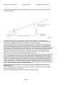
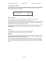
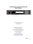
The following simple diagram illustrates the situation of the two antennas measuring the signal phase
from one GPS satellite.
The vector between the two antennas is often referred to as the baseline. One antenna will be
designated as the primary antenna and the other as the secondary antenna. The true heading derived
will represent the heading from the primary antenna to the secondary antenna.
The GPS compass engine can measure the instantaneous phase of the carrier at both antennas but it
can't directly determine the total number of carrier waves between the antennas. The compass engine
must be told the actual distance between the two antennas. Knowing the baseline length and phase
information from multiple GPS satellites, the compass engine sorts through the many (possibly thousands
of) combinations of orientations between the two antennas. The compass engine's algorithm eventually
determines what heading must exist between the two antennas in order to fit all the data collected.
This discussion of the GPS compass algorithm is extremely rudimentary but is presented in order to
highlight some critical items associated with the installation of the unit:
1) the most critical item is that the two antennas be positioned where they have unobstructed views of the
sky. If the antennas don't receive signals on a direct path from the GPS satellites, the phase measured
won't be representative of the true geometry of the antenna array. If the direct path to a GPS satellite is
blocked, the antennas may still receive a signal reflected off of some surface (multipath) in the area of the
antennas. This reflecting surface may be buildings in the area or other structures associated with the
satellite antenna system. The GPS compass algorithm can't distinguish between signals received directly
or from a reflected path. It is possible that the algorithm can determine an incorrect heading solution
based on multipath signals. Note that the high performance antennas supplied have a large ground plane
area in order to minimize the chance of multipath reception.
The Hemisphere manual states that the antenna array must be positioned with no structures
above its horizon.
2) the distance between the antennas must be carefully measured and programmed into the compass
engine via the RC3000 antenna controller.
Procedures to address these items are discussed in the installation section.
HGPS-2
RC3000 Antenna Controller
Appendix HGPS
Hemisphere GPS Compass
2.0 INSTALLATION
This section details specific installation procedures applicable only to the HGPS compass option.
Proceed with all other installation steps as described in the baseline RC3000 manual and any other
applicable appendices.
The following installation steps described in the baseline manual are superceded by those described in
this appendix:
GPS mounting (2.1.2)
Compass mounting 2.1.3
Navigation sensor wiring (2.2.6)
Navigation sensor communication (2.3.8)
Compass calibration (2.4.1)
2.1.2 GPS Receiver Mounting
The HGPS compass option consists of a circuit card containing the GPS compass engine and two high
performance GPS antennas. Coax cables will connect the RC3000 to the two GPS antennas. Multiple
factors must be considered when positioning the 2 antennas (antenna array).
1) The two GPS antennas may be positioned between 0.5 and 2.0 meters apart. The further the
antennas are placed (up to 2 meters), the better the theoretical performance of the heading solution will
be. The distance between the antennas will need to be precisely measured and programmed into the
RC3000 during the calibration procedure discussed later.
2) The two antennas must be placed where they both have unobstructed views of the sky. Do not
sacrifice either antenna's view of the sky though in order to obtain a longer baseline. No structure
associated with the satellite antenna system should rise more than 10 degrees above the horizon of the
GPS antenna array. This restriction also applies to external structures within the area that the antenna
array will be functioning. If the 10 degree and above view cannot be achieved, the elevation_mask
parameter must be changed (see 3.3.2.9 GPS Compass Calibration).
3) Coax cables should be limited to lengths that would realize 15 dB of loss or less at GPS L1 (1.575
GHz). This limits the length of RG58 cable (0.78 dB/m) to approximately 10 m. when connector loss is
included. RG8 material (0.36 dB/m) may be used to about 20m.
4) The antennas should also be placed where the vector between the two will be as close to parallel to
the ground (level) as possible when the antenna controller polls the GPS engine for a heading reading.
The suggestion to have the antenna array within 10 degrees of level allows the heading algorithm to
disregard some possible mathematically correct heading solutions for antenna array tilts greater than 10
degrees. The engine compass will be programmed to assume this level situation exists. If level
operation cannot be achieved, the level_operation parameter must be changed (see 3.3.2.9 GPS
Compass Calibration).
2.1.3 Compass Mounting
Since the compass function is contained within the HGPS compass unit, no additional mounting beyond
that described in 2.1.2 are required.
2.2.6 Navigation Sensor Wiring
The two GPS antennas will be connected via TNC connectors labeled "Primary" and "Secondary."
HGPS-3
RC3000 Antenna Controller
Appendix HGPS
Hemisphere GPS Compass
2.3.8 Navigation Sensor Communication
After connecting the GPS antennas to the RC3000, verify that the units are communicating by observing
data flow via the GPS Serial Port Diagnostics screen described in 3.3.2.6.
2.4.1 Compass Calibration
In order for the compass engine to perform properly, several items describing the installation of the GPS
antenna array will need to be programmed:
1) the distance between the center of the two antennas will need to be measured to within several
millimeters. This value must then be entered into the ANTENNA SEPARATION parameter at the GPS
Compass Calibration screen (3.3.2.9).
NOTE: it may be difficult to determine the center of the round GPS antennas. Measuring between the
edges of the antennas may prove easier.
2) if the level operation situation described in the GPS mounting section does not exist, the LEVEL
OPERATION parameter (3.3.2.9) must be set to NO.
3) if permanent obstructions 10 degrees above the antenna array's horizon exist, the ELEVATION MASK
parameter (3.3.2.9) must be set.
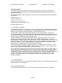
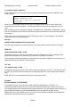
4) the relationship between the direction the antenna array is pointing and the satellite antenna's azimuth
reference direction (AZIM 0.0) must be described to the controller. In the example figure below, the
azimuth reference direction is 90 degrees counterclockwise from the direction of the GPS antenna array.
Enter a value of -90.0 in the fluxgate_offset item on the AZIMUTH CALIBRATION screen (3.3.1.2.3 in
baseline manual).
5) if the GPS antenna array is mounted such that the satellite antenna must be moved to a certain
position before determining heading, the COMPASS item in the SYSTEM DEFINITION screen (3.3.1.2 in
baseline manual) must be set to the "antenna mount" value. If this situation exists, the RC3000 will know
to move the satellite antenna to the deploy position before attempting to read a heading from the GPS
compass.
HGPS-4
RC3000 Antenna Controller
Appendix HGPS
Hemisphere GPS Compass
COMPASS CHECKOUT
After programming the various settings, the performance of the GPS compass should be confirmed. With
the GPS antenna array oriented in a fairly well known true heading (account for local magnetic variation if
using a magnetic compass as reference), put the RC3000 into the GPS Compass Heading maintenance
screen (3.3.2.7).
Observe that the instantaneous and average true headings are close to the expected value.
If possible, allow this mode to operate for several hours and observe the maximum and minimum true
headings. Over the course of several hours, the GPS constellation of satellites will continuously change
and present different geometries to the compass algorithm. If the max and min are within a degree of
each other, the GPS compass is probably working well.
NOTE: during this checkout we are observing the raw true heading of the GPS antenna array. Any
compass offset discussed in item 4 above will not be applied to the values shown in the GPS Compass
Heading maintenance screen.
HGPS-5
RC3000 Antenna Controller
Appendix HGPS
Hemisphere GPS Compass
3.0 DETAILED OPERATION
With the HGPS compass option properly installed, the operation of the RC3000 will be almost exactly as
described in the baseline user's manual with just a few exceptions noted below.
3.2.2.3 LOCATE mode
Upon entering LOCATE mode, the RC3000 will try to automatically obtain latitude, longitude and heading
as described in the baseline manual. Since the GPS compass provides true heading there is no need for
the RC3000 to calculate an estimate of the local magnetic variation. A flashing "MAGVAR" will therefore
not appear after the lat/lon has been obtained and the system clock has been synchronized to GPS time.
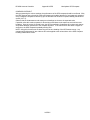
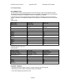
3.3.2 Maintenance Items
Items 6, 7 and 9 of the MAINTENANCE mode are different reflecting the use of the GPS compass
engine.
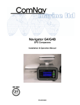
1-VOLTS
2-DRIVE RESET
MAINTENANCE
3-TIME
4-AGC ADJ 5-LIMITS 6-GPS COM
7-CSI HDG 8-AZEL
9-CSI CAL 0-SHAKE
<0-9>SELECT <MODE>CONFIG
S1-GTRv1.46
3.3.2.6 GPS Serial Port Diagnostics
As described in the baseline manual, this screen will reflect the raw data being received from the GPS
unit. The data seen will be slightly different from that described in the baseline manual:
- no $PGRMT sentence will be present as this is a proprietary message from the Garmin GPS
- the $GPRMC sentence should still appear at a 1 hz. rate but will contain additional characters for time,
latitude and longitude. The following is an example $GPRMC message from the HGPS unit:
$GPRMC,133544,V,3856.0856,N,09444.8377, W,000.0,000.0,080499,003.6,E*7B
Also compared to the Garmin unit, when the CSI is reporting that no current navigation solution is
available ("V" in the sentence vs. "A"), no data will be displayed between the comma delimiters. In this
case the sentence will appear something like:
$GPRMC,,V,,,, ,,,,,*66
- the $GPGGA will appear at a 0.2 hz rate vs. 1 hz for the Garmin unit.
- additionally the $GPHDT sentence supplying the GPS engine's estimate of true heading will be provided
at a 1 hz. rate. This sentence will typically not appear until a valid navigation (lat/lon) solution has been
achieved by the GPS engine. The following is an example sentence:
$GPHDT,123.4,T*5A
As with the $GPRMC and $GPGGA sentences, if no valid true heading is currently being derived, the
sentence will show no data between the comma delimiters ($GPHDT,,,*4C).
HGPS-6
RC3000 Antenna Controller
Appendix HGPS
Hemisphere GPS Compass
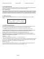
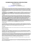
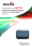
3.3.2.7 GPS Compass Heading
This mode allows the user to observe the true heading generated by the HGPS compass over a period of
time. The ability to monitor the true heading over time should help in predicting the performance of the
HGPS compass installation and calibration.
GPS COMPASS
SEC: 1315
CNT: 1300
BLN:
15
HDT: 88.5 MAX: 88.9
AVG: 88.4 MIN: 88.0
SEC: , CNT: , BLN:
These fields provide statistics on the $GPHDT sentence received from the GPS compass.
The SEC field shows the number of seconds that the mode has been active.
The CNT field shows the number of valid $GPHDT sentences received. When the RC3000 is getting true
heading data from the CSI unit, this number should increase at a similar rate as the SEC field since the
GPS unit is programmed to output $GPHDT at a 1 Hz. rate.
The BLN field shows the number of $GPHDT sentences received that didn't have heading data in them.
This indicates that the GPS unit has developed a lat/lon solution but is unable to develop a correct
heading solution.
HDT:, AVG:
The HDT field shows the latest value received from the $GPHDT sentence.
The AVG field shows the average heading value since the mode started.
MAX:, MIN:
These fields show the maximum and minimum heading values received since the mode started. When
working properly, the spread of values should be no more than 1 or 2 degrees. Shorter baseline lengths
will yield wider value swings than longer baseline lengths.
NOTE: If the antenna array is pointing towards North (0.0), the max and min values may be deceiving
since a value like 359.9 may only indicate an actual swing of 0.2 from a 0.1 reading. It will typically be
best to have the antenna array pointing away from North when running a long term test of the heading
solution.
HGPS-7
RC3000 Antenna Controller
Appendix HGPS
Hemisphere GPS Compass
3.3.2.9 GPS Compass Calibration
This mode allows the user to program several variables associated with a particular installation of the
HGPS compass.
CSI CAL
CHOOSE PARAMETER TO SET
<1>ANT SEP <2>LEVEL OP <3>TILT AID
<4>EL MASK
When one of the variables is selected for change, the displayed value will be 0 not the actual value
currently stored in the GPS compass. To ensure the desired value is stored, go ahead and enter the
value.
After entering the value, the display will indicate " STORING DATA - REQUIRES 15 SECONDS". During
this time, the RC3000 communicates with the GPS compass and allows the unit to rewrite the parameter
in its memory.
NOTE: when each of the following four fields is entered, the value "0" will be displayed. This does not
represent the current value of the setting.
ANT SEP:
ENTER ANTENNA SEPARATION <500-2000>MM
Enter the distance between the installed antennas. Accuracy to within several millimeters is required.
LEVEL OP:
LEVEL OPERATION <0>NO <1>YES
The programmed value for this item as the GPS compass is supplied will be "YES", indicating that the
antennas are guaranteed to be positioned in a plane within 10 degrees of horizontal.
If level operation cannot be guaranteed, it may take longer to generate a heading solution and there is a
greater possibility of generating an incorrect solution.
TILT AID:
TILT AIDING <0>NO <1>YES
The programmed value for this item as the GPS compass is supplied will be "NO". To be able to program
as "YES", the enclosure must be positioned in the same plane and in the same direction as the antenna
array.
NOTE: RCI does not recommended at this time to set this value to YES.
EL MASK:
ELEVATION MASK <5-60>DEGREES
The programmed value for this item as the GPS compass is supplied will be 10 degrees. It is
recommended that the antenna array be positioned so that both antennas have a clear view of the sky.
The 10 degree default value represents the idea that the signal from any GPS satellite that is less than 10
degrees high will probably be experiencing degradation due to atmospheric refraction effects.
Masking more of the sky eliminates the use of more of the GPS satellite constellation and increases the
chance that no heading solution may be generated.
HGPS-8
RC3000 Antenna Controller
Appendix HGPS
Hemisphere GPS Compass
4.0 Troubleshooting
NO COMMUNICATION
The GPS engine needs to be programmed to the correct settings to work with the RC3000 controller.
The engine will come from RCI programmed to the correct settings. This programming is accomplished
via the Window's program "PocketMaxPC version 2.0" supplied by Hemisphere.
If the GPS engine must be reprogrammed the following tables are included to document the desired
settings. Note that the PocketMaxPC software will be looking for a "Hemisphere Vector" device at 4800
baud.
GPS VALUES
DiffMode: SBAS
Elevation Mask: 5
This Baud: 4800
Other Baud: 9600
COAST: 1800
This Port
Other Port
$GPGGA
5 sec
OFF
$GPGLL
OFF
OFF
$GPGSA
OFF
OFF
$GPGST
OFF
OFF
$GPGSV
OFF
OFF
$GPRMC
1 Hz
OFF
$GPRRE
OFF
OFF
$GPVTG
OFF
OFF
$GPZDA
OFF
OFF
Bin 95
OFF
OFF
Bin 96
OFF
OFF
NOTE: The RC3000 software was developed to work with a GPS engine containing ARM firmware vesion
1.5D DSP firmware version 46.
HDG VALUES
Tilt Aiding: unchecked
Pitch: checked
Roll: unchecked
Gyro Aiding: unchecked
Negative Tilt: unchecked
FLIPBRD: unchecked
Magnetic Aiding: unchecked
Level Operation : checked
Heading Tau: 0.5
Heading Rate Tau : 2.0
COG Tau: 0
Speed Tau: 0
Heading Bias: 0
Pitch/Roll Bias: 0
MSEP: 0.5
This Port
Other Port
$GPHDT
1 Hz
OFF
$GPROT
OFF
OFF
$PSAT,HPR
OFF
OFF
INCORRECT HEADING
- reprogram the baseline length to confirm it is stored correctly in the GPS compass
- check that any azimuth offset is described correctly to the RC3000
- run the GPS Heading maintenance function
HGPS-9