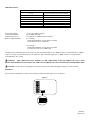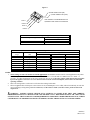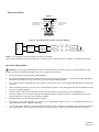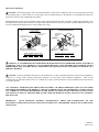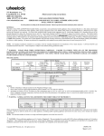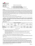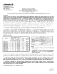
1
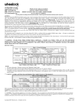
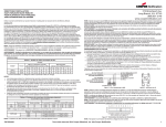
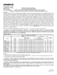
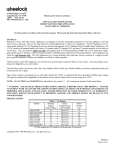
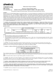
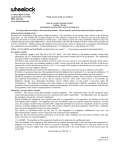
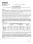
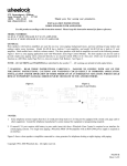
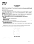
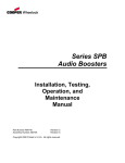
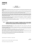
273 Branchport Avenue
Long Branch, N.J. 07740
(800) 631-2148
www.wheelockinc.com
Thank you for using our products.
INSTALLATION INSTRUCTIONS
SUPERVISED SELF-AMPLIFIED SPEAKER
Use this product according to this instruction manual. Please keep this instruction manual for future reference.
MODEL NUMBERS:
Speaker
SA-S70-R
Speaker
SA-S70-W
Speaker
SA-S90-R
Speaker
SA-S90-W
Supervised Self-Amplified Speaker
Supervised Self-Amplified Speaker
Supervised Self-Amplified Speaker
Supervised Self-Amplified Speaker
GENERAL:
The Supervised Self-Amplified Speaker provides a choice of 6 different sound output levels and operates with audio input levels of
0.5 VRMS (e.g., from Wheelock’s SALL-15S or any other 0.5V-RMS audio output source Listed for Fire Protective Signaling
Service) and 25 VRMS, all by means of selectable switch settings. The Low Profile design incorporates a high efficiency speaker for
maximum output at minimum power across a frequency range of 400Hz to 4000Hz, and features a sealed back construction for extra
protection and improved audibility. The appliance mounts onto a 4” square deep backbox with an extension ring. (See Mounting
Options.) All inputs are polarized for compatibility with standard reverse polarity supervision of circuit wiring via a Control Panel.
NOTE: All CAUTIONS and WARNINGS are identified by the symbol
. All warnings are printed in bold capital letters.
WARNING: THE SPEAKER APPLIANCE IS A "FIRE ALARM DEVICE - DO NOT PAINT."
WARNING: PLEASE READ THESE INSTRUCTIONS CAREFULLY BEFORE USING THIS PRODUCT. THE
SUPERVISED SELF-AMPLIFIED SPEAKER MUST BE FIELD SET TO THE DESIRED SOUND OUTPUT LEVEL
BEFORE IT IS INSTALLED. THIS IS DONE BY PROPERLY ADJUSTING A FOUR-POSITION SWITCH IN
ACCORDANCE WITH THESE INSTRUCTIONS. INCORRECT SETTINGS WILL RESULT IN IMPROPER
PERFORMANCE AND MAY DAMAGE THE PRODUCT, WHICH COULD RESULT IN PROPERTY DAMAGE AND
SERIOUS INJURY OR DEATH TO YOU AND/OR OTHERS.
WARNING: CHECK THE MINIMUM AND MAXIMUM OUTPUT OF THE POWER SUPPLY AND STANDBY
BATTERY AND SUBTRACT THE VOLTAGE DROP FROM THE CIRCUIT WIRING RESISTANCE TO DETERMINE
THE APPLIED VOLTAGE TO THE APPLIANCES.
Copyright 2004 Wheelock, Inc. All rights reserved.
P84502 C
Sheet 1 of 6
SPECIFICATIONS:
Table 1A: Sound Output Level
Sound
Level
Rated Reverberant dBA at
10 ft per UL 1480 for 0.5-V and 25-V Settings
6
5
4
3
2
1
84
82
77
75
71
69
NOTE: See Table 3 Sound Output Level Selection for use of settings “A” and “B”.
Power Input Voltage:
Current Consumption:
Appliance Input Level:
Appliance Input Impedance:
16.0 to 33.0 VDC, regulated
120 mA RMS maximum
0.5 V RMS or 25 V RMS (Switch selectable)
0.5-V Setting:
Greater than 400 Ohms, or equivalent to less than
1/1000 W (0.001 W or 1 mW) load
25-V Setting:
Greater than 20 kOhms, or equivalent to less than
1/32 W (0.03125 W or 31.25 mW) load
Sound pressure level measurements were made at 16 VDC with audio inputs of 0.5 V RMS in the 0.5-V setting and with 25 V RMS
in the 25-V setting. Current measurements were made at 33 VDC with audio inputs of 0.5 V RMS in the 0.5-V setting and with
25 V RMS in the 25-V setting.
WARNING: THIS APPLIANCE WAS TESTED TO THE OPERATING VOLTAGE LIMITS OF 16-33 VOLTS
REGULATED POWER. DO NOT APPLY 80% AND 110% OF THESE VOLTAGE VALUES FOR SYSTEM OPERATION.
CAUTION: The Speaker is not designed to be used on coded systems in which the applied voltage is cycled on and off.
SETTINGS:
The switch on the PCB (SW1) is used to select the input voltage and sound output level, see Figure 1.
Figure 1:
TB1
AD+
AD+24
GND
ST+
ON
ST-
1
2
3
4
SW1
ON
1
2
3
4
SW1
P84502 C
Sheet 2 of 6
Figure 2:
SLIDE HERE FOR (0N)
SLIDE HERE FOR (OFF)
POS 1
USE A SMALL SCREWDRIVER TO
CHANGE THE SWITCH POSITION.
POS 2
POS 3
POS 4
Table 2: Audio Input Voltage Mode Selection
Audio Input Voltage Mode
Switch Settings (SW1)
POS 1
0.5 V RMS
ON
25 V RMS
OFF
Sound Output
Level
A1
B1
62
5
4
3
2
1
Table 3: Sound Output Level Selection
Relative Level
Switch Settings (SW1)
(dB)
POS 4
POS 3
+6 (typical)
OFF
ON
+3 (typical)
OFF
ON
0 (Reference)
OFF
OFF
-33 (typical)
OFF
OFF
-63 (typical)
ON
ON
-93 (typical)
ON
ON
-123 (typical)
ON
OFF
-153 (typical)
ON
OFF
POS 2
OFF
ON
OFF
ON
OFF
ON
OFF
ON
NOTES:
1. These settings are not to be used in UL Listed applications and should be used in non-UL Listed applications only when
the audio input level is not at the rated value – 0.5 V RMS for the 0.5-V mode and 25 V RMS for the 25-V mode – to
provide 3- or 6-dB compensation for line losses and/or low drive levels. Using these settings while applying the rated audio
input to the appliance will cause excessive distortion and increased current consumption, and it is not a recommended
operating condition.
2. This is the setting used as a reference level for the other settings in this table.
3. These are typical values with respect to the reference level (Sound Output Level 6: 0 dB), and are included only to assist the
user in choosing a setting during installation. However, use the values in Table 1, not these values, for the actual sound
output levels.
WARNING: DOUBLE CHECK SWITCH (SW1) SETTINGS TO MAKE SURE THEY ARE CORRECT.
IMPROPER SETTINGS CAN DAMAGE THE UNIT OR RESULT IN A DISTORTED OUTPUT OR A dBA SOUND
OUTPUT LEVEL THAT IS BELOW CODE REQUIREMENTS FOR PUBLIC MODE FIRE PROTECTION, WHICH
COULD RESULT IN PROPERTY DAMAGE AND SERIOUS INJURY OR DEATH TO YOU AND/OR OTHERS.
P84502 C
Sheet 3 of 6
WIRING DIAGRAMS:
Figure 3:
+
+
STROBE
-
-
FROM PRECEDING +
AMPLIFIER OR
AUDIO
SAFEPATH PANEL
-
+ TO NEXT SIGNAL
OR END 0F LINE
RESISTOR
-
+
POWER
+
-
ST+
ST-
+24
AD+
GND
AD-
Figure 4: Sync Modules/Sync Strobes Connection Diagram
FIRE
ALARM
+
INPUT
CONTROL
PANEL
(FACP)
+
SYNC *
OUTPUT
MODULES
-
-
STROBE OR
COMBINATION
STROBE AND
AUDIBLE #1
+
-
STROBE OR
COMBINATION
STROBE AND
AUDIBLE #2
+
-
+
-
STROBE OR
COMBINATION
STROBE AND
AUDIBLE #N
END OF LINE
RESISTOR
NOTE: All wiring must be all power-limited or all non-power-limited.
*Refer to Sync Module instruction sheets SM (P83123), DSM (P83177) or Wheelock’s Power Supplies for additional information.
MOUNTING PROCEDURES:
CAUTION: Check that the installed product will have sufficient clearance and wiring room prior to installing backboxes and
conduit, especially if sheathed multiconductor cable or 3/4" conduit fittings are used.
1.
The SA Series has an integrated Speaker Mounting Plate.
2.
The Speaker Mounting Plate must be oriented correctly when it is mounted to the backbox. Turn the Speaker Mounting Plate so
that the arrows and the word “TOP” point to the top side of the Speaker Mounting Plate.
3.
First mount the Speaker Mounting Plate to the backbox. Next slide the grille over the Speaker Mounting Plate and attach with
(2) screws.
4.
When terminating field wires, do not use more lead length than required. Excess lead length could result in insufficient wiring
space for the signaling appliance.
5.
Conduit entrances to the backbox should be selected to provide sufficient wiring clearance for the installed product.
6.
Do not pass additional wires (used for other than the signaling appliance) through the backbox. Such additional wires could
result in insufficient wiring space for the signaling appliance.
7.
Mounting hardware for each mounting option is supplied.
8.
The SA Series can be flush mounted to a 4” square by 1-1/2” deep backbox with a 4” square 1-1/2” extension ring (Figure A) or
surface mounted to a Surface Backbox (Figure B).
9.
Use care and proper techniques to position the field wires in the backbox so that they use minimum space and produce minimum
stress on the product. This is especially important for stiff, heavy gauge wires and wires with thick insulation or sheathing.
P84502 C
Sheet 4 of 6
MOUNTING OPTIONS:
CAUTION: The following figures show the maximum number of field wires (conductors) that can enter the backbox used with
each mounting option. If these limits are exceeded, there may be insufficient space in the backbox to accommodate the field wires
and stresses from the wires could damage the product.
Although the limits shown for each mounting option comply with the National Electrical Code (NEC), Wheelock recommends use of
the largest backbox option shown and the use of approved stranded field wires, whenever possible, to provide additional wiring room
for easy installation and minimum stress on the product from wiring.
A
(NON-STROBE)
4" SQ. X 2-1/8"
EXTENSION RING *
SURFACE MOUNTING
(NON-STROBE SPEAKER)
C
FLUSH MOUNTING
4" SQ. X 1-1/2"
BACKBOX
SURFACE
BACKBOX
(SBB)
(2) #8-32
SCREWS
(2) #8-32
SCREWS
SPEAKER
MOUNTING
PLATE
SQUARE OR
ROUND GRILLE
(2) #6-19
SCREWS
MAXIMUM NUMBER OF CONDUCTORS
AWG #18 AWG #16 AWG #14 AWG#12
4
4
4
4
SPEAKER
MOUNTING
PLATE
SQUARE
GRILLE
(2) #6-19
SCREWS
MAXIMUM NUMBER OF CONDUCTORS
AWG #18 AWG #16 AWG #14 AWG#12
4
4
4
4
WARNING: IF A SUPERVISED SELF-AMPLIFIED SPEAKER APPLIANCE IS OPERATED WITHIN 15 INCHES OF
A PERSON'S EAR, IT CAN PRODUCE A SOUND PRESSURE LEVEL THAT EXCEEDS THE MAXIMUM 120 dBA
PERMITTED BY ADA AND OSHA RULES. EXPOSURE TO SUCH SOUND LEVELS CAN RESULT IN DAMAGE TO A
PERSON'S HEARING.
CAUTION: Check the installation instructions of the manufacturers of other equipment used in the system for any guidelines or
restrictions on wiring and/or locating Notification Appliance Circuits (NAC) and notification appliances. Some system
communication circuits and/or audio circuits, for example, may require special precautions to assure immunity from electrical noise
(e.g. audio crosstalk).
ANY MATERIAL EXTRAPOLATED FROM THIS DOCUMENT OR FROM WHEELOCK MANUALS OR OTHER
DOCUMENTS DESCRIBING THE PRODUCT FOR USE IN PROMOTIONAL OR ADVERTISING CLAIMS, OR FOR
ANY OTHER USE, INCLUDING DESCRIPTION OF THE PRODUCT'S APPLICATION, OPERATION, INSTALLATION
AND TESTING IS USED AT THE SOLE RISK OF THE USER AND WHEELOCK WILL NOT HAVE ANY LIABILITY
FOR SUCH USE.
IMPORTANT:
READ SEPARATE "GENERAL INFORMATION" SHEET FOR INFORMATION ON THE
PLACEMENT, LIMITATIONS, INSTALLATION, FINAL CHECKOUT, AND PERIODIC TESTING OF NOTIFICATION
APPLIANCES.
P84502 C
Sheet 5 of 6
Limited Warranty
Wheelock products must be used within their published specifications and must be PROPERLY specified, applied, installed, operated,
maintained and operationally tested in accordance with these instructions at the time of installation and at least twice a year or more
often and in accordance with local, state and federal codes, regulations and laws. Specification, application, installation, operation,
maintenance and testing must be performed by qualified personnel for proper operation in accordance with all of the latest National
Fire Protection Association (NFPA), Underwriters' Laboratories (UL), Underwriters' Laboratories of Canada (ULC), National
Electrical Code (NEC), Occupational Safety and Health Administration (OSHA), local, state, county, province, district, federal and
other applicable building and fire standards, guidelines, regulations, laws and codes including, but not limited to, all appendices and
amendments and the requirements of the local authority having jurisdiction (AHJ). Wheelock products when properly specified,
applied, installed, operated, maintained and operationally tested as provided above are warranted against mechanical and electrical
defects for a period of three years from date of manufacture (as determined by date code). Correction of defects by repair or
replacement shall be at Wheelock's sole discretion and shall constitute fulfillment of all obligations under this warranty. THE
FOREGOING LIMITED WARRANTY SHALL IMMEDIATELY TERMINATE IN THE EVENT ANY PART NOT FURNISHED
BY WHEELOCK IS INSTALLED IN THE PRODUCT. THE FOREGOING LIMITED WARRANTY SPECIFICALLY
EXCLUDES ANY SOFTWARE REQUIRED FOR THE OPERATION OF OR INCLUDED IN A PRODUCT. WHEELOCK
MAKES NO REPRESENTATION OR WARRANTY OF ANY OTHER KIND, EXPRESS, IMPLIED OR STATUTORY
WHETHER AS TO MERCHANTABILITY, FITNESS FOR A PARTICULAR PURPOSE OR ANY OTHER MATTER.
USERS ARE SOLELY RESPONSIBLE FOR DETERMINING WHETHER A PRODUCT IS SUITABLE FOR THE USER'S
PURPOSES, OR WHETHER IT WILL ACHIEVE THE USER'S INTENDED RESULTS. THERE IS NO WARRANTY AGAINST
DAMAGE RESULTING FROM MISAPPLICATION, IMPROPER SPECIFICATION, ABUSE, ACCIDENT OR OTHER
OPERATING CONDITIONS BEYOND WHEELOCK'S CONTROL.
SOME WHEELOCK PRODUCTS CONTAIN SOFTWARE. WITH RESPECT TO THOSE PRODUCTS, WHEELOCK DOES
NOT WARRANTY THAT THE OPERATION OF THE SOFTWARE WILL BE UNINTERRUPTED OR ERROR-FREE OR
THAT THE SOFTWARE WILL MEET ANY OTHER STANDARD OF PERFORMANCE, OR THAT THE FUNCTIONS OR
PERFORMANCE OF THE SOFTWARE WILL MEET THE USER'S REQUIREMENTS. WHEELOCK SHALL NOT BE LIABLE
FOR ANY DELAYS, BREAKDOWNS, INTERRUPTIONS, LOSS, DESTRUCTION, ALTERATION, OR OTHER PROBLEMS
IN THE USE OF A PRODUCT ARISING OUT OF OR CAUSED BY THE SOFTWARE.
THE LIABILITY OF WHEELOCK ARISING OUT OF THE SUPPLYING OF A PRODUCT, OR ITS USE, WHETHER ON
WARRANTIES, NEGLIGENCE, OR OTHERWISE, SHALL NOT IN ANY CASE EXCEED THE COST OF CORRECTING
DEFECTS AS STATED IN THE LIMITED WARRANTY AND UPON EXPIRATION OF THE WARRANTY PERIOD ALL
SUCH LIABILITY SHALL TERMINATE. WHEELOCK IS NOT LIABLE FOR LABOR COSTS INCURRED IN REMOVAL,
REINSTALLATION OR REPAIR OF THE PRODUCT BY ANYONE OTHER THAN WHEELOCK OR FOR DAMAGE OF ANY
TYPE WHATSOEVER, INCLUDING BUT NOT LIMITED TO, LOSS OF PROFIT OR INCIDENTAL OR CONSEQUENTIAL
DAMAGES. THE FOREGOING SHALL CONSTITUTE THE SOLE REMEDY OF THE PURCHASER AND THE EXCLUSIVE
LIABILITY OF WHEELOCK.
IN NO CASE WILL WHEELOCK'S LIABILITY EXCEED THE PURCHASE PRICE PAID FOR A PRODUCT.
Limitation of Liability
WHEELOCK'S LIABILITY ON ANY CLAIM OF ANY KIND, INCLUDING NEGLIGENCE AND BREACH OF WARRANTY,
FOR ANY LOSS OR DAMAGE RESULTING FROM, ARISING OUT OF, OR CONNECTED WITH THIS CONTRACT, OR
FROM THE MANUFACTURE, SALE, DELIVERY, RESALE, REPAIR OR USE OF ANY PRODUCT COVERED BY THIS
ORDER SHALL BE LIMITED TO THE PRICE APPLICABLE TO THE PRODUCT OR PART THEREOF WHICH GIVES RISE
TO THE CLAIM. WHEELOCK'S LIABILITY ON ANY CLAIM OF ANY KIND SHALL CEASE IMMEDIATELY UPON THE
INSTALLATION IN THE PRODUCT OF ANY PART NOT FURNISHED BY WHEELOCK. IN NO EVENT SHALL
WHEELOCK BE LIABLE FOR ANY CLAIM OF ANY KIND UNLESS IT IS PROVEN THAT OUR PRODUCT WAS A
DIRECT CAUSE OF SUCH CLAIM. FURTHER, IN NO EVENT, INCLUDING IN THE CASE OF A CLAIM OF
NEGLIGENCE, SHALL WHEELOCK BE LIABLE FOR INCIDENTAL OR CONSEQUENTIAL DAMAGES. SOME STATES
DO NOT ALLOW THE EXCLUSION OR LIMITATION OF INCIDENTAL OR CONSEQUENTIAL DAMAGES, SO THE
PRECEDING LIMITATION MAY NOT APPLY TO ALL PURCHASERS.
04/04
P84502 C
Sheet 6 of 6