1
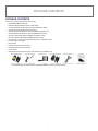
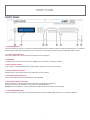
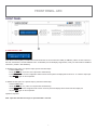
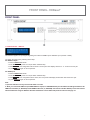
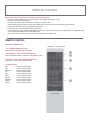
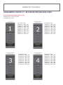
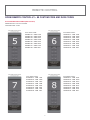
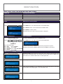
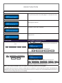
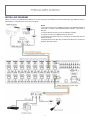
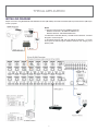
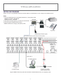
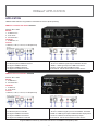
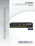
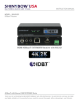
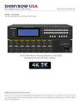
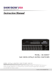
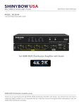
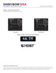
M U LT IM EDIA AUDIO A ND V IS UA L
INSTRUCTION MANUAL
MODEL : SB-5680CAK
8x8 HDMI-HDBaseT Matrix Switcher
8x8 HDMI-HDBaseT Matrix Switch with Auxiliary Audio I/O
HDMI-HDBaseT-AUDIO MATRIX SWITCHER SERIES
Thank you for purchasing the SB-5680CAK HDMI-HDBaseT Matrix Switcher. You will find this unit easy to install
and highly reliable but it is essential that you read this manual thoroughly before attempting to use 8x8 HDMIHDBaseT Matrix switcher.
SAFETY INFORMATION
1.
To ensure the best results from this product, please read this manual and all other documentation before operating your equipment.
Retain all documentation for future reference.
2.
Follow all instructions printed on unit chassis for proper operation.
3.
To reduce the risk of fire, do not spill water or other liquids into or on the unit, or operate the unit while standing in liquid.
4.
Make sure power outlets conform to the power requirements listed on the back of the unit. Keep unit protected from rain, water and
excessive moisture.
5.
Do not attempt to clean the unit with chemical solvents or aerosol cleaners, as this may damage the unit. Dust with a clean dry cloth.
6.
Do not use the unit if the electrical power cord is frayed or broken. The power supply cords should be routed so that they are not
likely to be walked on or pinched by items placed upon or against them, paying particular attention to cords and plugs, convenience
receptacles, and the point where they exit from the appliance.
7.
Do not force switched or external connections in any way. They should all connect easily, without needing to be forced.
8.
Always operate the unit with the AC ground wire connected to the electrical system ground. Precautions should be taken so that the
means of grounding of a piece of equipment is not defeated.
9.
AC voltage must be correct and the same as that printed on the rear of the unit. Damage caused by connection to improper AC
voltage is not covered by any warranty.
10. Turn power off and disconnect unit from AC current before making connections.
11. Never hold a power switch in the “ON” position.
12. This unit should be installed in a cool dry place, away from sources of excessive heat, vibration, dust, moisture and cold. Do not use
the unit near stoves, heat registers, radiators, or other heat producing devices.
13. Do not block fan intake or exhaust ports. Do not operate equipment on a surface or in an environment which may impede the normal
flow of air around the unit, such as a bed, rug, carpet, or completely enclosed rack. If the unit is used in an extremely dusty or smoky
environment, the unit should be periodically “blown free” of foreign dust and matter.
14. To reduce the risk of electric shock, do not remove the cover. There are no user serviceable parts inside. Refer all servicing to
qualified service personnel. There are no user serviceable parts inside.
15. When moving the unit, disconnect input ports first, then remove the power cable; finally, disconnect the interconnecting cables to
other devices.
16. Do not drive the inputs with a signal level greater than that required to drive equipment to full output.
17. The equipment power cord should be unplugged from the outlet when left unused for a long period of time.
18. Save the carton and packing material even if the equipment has arrived in good condition. Should you ever need to ship the unit,
use only the original factory packing.
19. Service Information Equipment should be serviced by qualifier service personnel when:
A. The power supply cord or the plug has been damaged.
B. Objects have fallen, or liquid has been spilled into the equipment.
C. The equipment has been exposed to rain
D. The equipment does not appear to operate normally, or exhibits a marked change in performance
E. The equipment has been dropped, or the enclosure damaged.
THIS SAFETY INFORMATION IS OF A GENERAL NATURE AND MAY BE SUPERSEDED BY INSTRUCTIONS CONTAINED WITHIN THIS MANUAL
TABLE OF CONTENTS
CONTENTS
SAFETY PRECAUTIONS
INTRODUCTION ...............................................................1
PACKAGE CONTENTS .................................................. 2
FEATURES ....................................................................... 3
SPECIFICATIONS ............................................................ 4
FRONT PANEL ................................................................. 5
FRONT PANEL- ARC ................................................... 6
FRONT PANEL - AUX ................................................. 7
FRONT PANEL - HDBaseT ......................................... 8
FRONT PANEL - EDID ............................................... 9
FRONT PANEL - ALL - OFF - LOCK - ENTER ............... 10
FRONT PANEL - RECALL - MEMORY ......................... 11
REAR PANEL ................................................................ 12
BACK PANEL - HDMI INPUT / OUTPUT ..................... 13
BACK PANEL - HDBaseT CONTROLS ..................... 14
BACK PANEL - HDBaseT I/O ................................... 15
HDBaseT I/O TRANSMISSION ..................................... 16
REMOTE CONTROL ...................................................... 17
EDID FUNCTIONS ......................................................... 21
TYPICAL APPLICATION ............................................... 24
HDBaseT APPLICATION .............................................. 29
IR EXTENDER ............................................................... 30
ETHERNET SERIAL INTERFACE ................................ 32
RS-232 PROTOCOL .................................................... 33
Please read all instructions before attempting to unpack, install or
operate this equipment and before connecting the power supply.
Please keep the following in mind as you unpack and install this
equipment:
• Always follow basic safety precautions to reduce the risk of fire,
electrical shock and injury to persons.
• To prevent fire or shock hazard, do not expose the unit to rain,
moisture or install this product near water.
• Never spill liquid of any kind on or into this product.
• Never push an object of any kind into this product through any
openings or empty slots in the unit, as you may damage parts
inside the unit.
• Do not attach the power supply cabling to building surfaces.
• Use only the supplied power supply unit (PSU). Do not use the
PSU if it is damaged.
• Do not allow anything to rest on the power cabling or allow any
weight to be placed upon it or any person walk on it.
• To protect the unit from overheating, do not block any vents or
openings in the unit housing that provide ventilation and allow
for sufficient space for air to circulate around the unit.
DISCLAIMERS
The information in this manual has been carefully checked and
is believed to be accurate. We assume no responsibility for any
infringements of patents or other rights of third parties which may
result from its use.
INTRODUCTION
The SB-5680CAK is professional 8x8 matrix routing switch.
Supporting eight (8) HDMI Inputs, 8 Auxiliary Audio Inputs, and
(8) HDBaseT Inputs. Supports 8 HDMI Outputs, 8 SPDIF Outputs,
and 8 HDBaseT (PoE) Outputs. The SB-5680CAK is based on the
HDBaseT standard and supports full resolution HDMI Video with
embedded PoE, Audio, RS-232, Ethernet and bi-directional IR,
all over a single CATx cable. With a signal bandwidth of 340Mhz,
there is no signal degradation. High Definition Digital signals
can be selected and distributed to any 8 Inputs to 16 Outputs
simultaneously (channel outputs mirrored). The Switcher is certified
as being fully CEC and HDCP 2.2 compliant, HDMI 4K2K V1.4a 3D
formats, data rates up to 6.75 Gbps. Supports UXGA/WUXGA/DVI
1920x1200 resolution to any HD displays. The SB-5680CAK has
1x HDBaseT and 1x HDMI connector for each Input and output,
effectively making this an 8 in x16 out switcher (same signal on
both outputs). Using the HDBaseT Input and our HDBaseT remote
Transmitter allows you to connect a source in a remote location.
Likewise, the HDBaseT Output and our HDBaseT Receiver allows
you to connect a display in a remote location. EDID management
can be selected between eight (8) different modes. Control is
provided via Front panel push buttons, IR remote, RS-232 or TCP/
IP (not a web-browser). An RS-232 Windows GUI interface is
provided for matrix routing control (Windows only).
We assume no responsibility for any inaccuracies that may be
contained in this document. We make no commitment to update or
to keep current the information contained in this document.
We reserve the right to make improvements to this document and/
or product at any time and without notice.
COPYRIGHT NOTICE
No part of this document may be reproduced, transmitted,
transcribed, stored in a retrieval system, or any of its part translated
into any language or computer file, in any form or by any means
— electronic, mechanical, magnetic, optical, chemical, manual, or
otherwise — without express written permission and consent
© Copyright 1997. All Rights Reserved.
Version 1.3 MAR 2014
TRADEMARK ACKNOWLEDGMENTS
All products or service names mentioned in this document may
be trademarks of the companies with which they are associated.
1
PACKAGE CONTENTS
PACKAGE CONTENTS
Check that you have the following components;
• SB-5680CAK Matrix Switcher
• Master wireless IR Remote Control (SW-5680)
• 8 each; Individual wireless IR Control (SW-5680-IR01~IR08)
• 19 inch Ear mount bracket (Part # 3U-440L)
• SB-101 IR Extender distance ~984 feet (300M) Transmitter set.
• SB-100 IR Extender distance ~984 feet (300M) Receiver set.
• SB-101C IR Extender distance 6ft(2M) Transmitter Cable.
• SB-100C IR Extender distance 6ft(2M) Receiver Cable.
• CD Contents : This manual, Windows GUI, ISP V1.0 Windows driver
• RS-232 Cable 6 feet (2M)
• ISO Screws
• RS-232 V2.0 Protocol Instructions
• Ethernet V2.0 Protocol Instructions
• Users Guide
• Worldwide Universal Power Supply 100~230 VAC, AC 50/60Hz, 10A.
-- SB-6320T HDBaseT Transmitters & SB-6320R HDBaseT Receiver sold separately. –
2
FEATURES
FEATURES
Based on HDBaseT; bi-directional IR, RS-232, Multi format Audio, Ethernet and PoE. Full resolution HD Video, all HDBaseT signals over
one CATx cable.
•
•
•
•
•
•
•
•
•
•
•
•
•
•
•
•
•
•
•
•
•
•
•
(8)x HDMI with Auxiliary Audio (Analog Audio) and (8)x HDBaseT Receiver devices matrix switched to
(8)x HDMI with S/PDIF outputs and (8)x HDBaseT Transmitter with PoE output to (8)x destinations.
Application HDBaseT Specification with PoE (optional), IR, RS-232, Multi Audio Format and HD
Video Signals over one CATx (6/6a/7) category cable.
HDMI digital Video w/embedded HDCP, DVI format and CEC/HDCP 2.2 compliant
Worldwide control EDID modes for HDMI full 4K2K HD Video resolutions.
Link speeds of up to 6.75 Gbps (link clock rate of 340MbHz), Support HDMI 4K2K, 1.4a 3D formats.
Wide range of HD resolutions from PC XGA to WUXGA 1920x1200 and HDTV/DTV HDMI resolutions
480i/480p, 576i/576p, 720p, 1080i/p & 4K2K.
Compatible with all HDMI source devices, PC monitors, Plasma HD display, HDTV and audio receivers or audio amplifiers.
Digital Video TMDS formats Resolution up to 4K2K with Deep color 36-bit.
Digital Audio Support :
• Dolby TrueHD,
• Dolby Digital,
• Dolby Digital Plug/ex,
• DTS,
• DTS-HD,
• DTS-HD Master,
• DTS-EX
• PCM,
• PCM2,
• LPCM2
Audio Input : Support Auxiliary Audio (Analog stereo audio).
Audio Output : Support Digital audio ARC or Digital audio S/PDIF ( from HDMI source or Auxiliary Audio )
Various User Interface controls:
• Windows based GUI control via RS-232 port
• Front Panel push button
• IR wireless remote controller
• Ethernet Switch control
• Third party RS-232 controller (via simple ASCII)
Support world wide (10)x control function keys: ARC / AUX/ HDBaseT / ALL / OFF / EDID / LOCK / RECALL / MEMORY / ENTER
Support EDID modes :
• Embedded EDID modes : FSS/ H24-3D/ H24-3D-M/ H36-3D/ H36-3D-M/ 4K2K-3D / DVI-D 1920x1200-60Hz/ AUTO
• External modes : Learning mode.
Automatic scanning input & output status via LCM show on front panel.
Support IR Remote and IR Extender with distance up to ~ 984 feet (300M) Maximum.
EDID configuration via Internal and External modes.
Support Universal power adaptor AC90V~AC230V, 50/60Hz.
The Switcher will remember that last state during a power cycle.
When power is removed and resorted, the last configuration will be invoked.
The Switcher will remember that last state during a power cycle.
When power is removed and resorted, the last configuration will be invoked.
3
SPECIFICATIONS
SPECIFICATIONS
•
•
•
•
•
•
•
•
•
•
•
•
•
•
•
•
•
•
•
•
•
•
•
Type of HDMI Switcher: 8x inputs To 8x Outputs HDMI & HDBaseT Matrix Switch with Audio and Extension
HDMI Support: HDMI 4K2K, 1080p-@60Hz, H36-bit Deep color, 3D of HDMI V1.4 formats
HDBaseT Support: Bi-directional IR, RS-232, Multi format Audio, Ethernet and PoE. over one CATx cable.
HDCP / CEC Support: HDCP 2.2 Compliant, CEC Compliant
Video Bandwidth: Double Data Rates: 340 MHz, Total 6.75Gbps bandwidth
Digital Video Support: HD:480i/ 480p/ 720p/ 1080i/p and 4K2K up to 36bit deep color
Inputs:
• 1. HDMI:
• 8x HDMI (HDMI or DVI digital source).
• 8x Audio (Auxiliary Audio : Analog Stereo Audio).
• 2. HDBaseT:
• 8x HDBaseT Receiver (via category cable CATx & RJ-45 connector)
• 8x IR in (Send IR signals To 8x Rooms via HDBaseT Transmitter)
• 1x ALL IR in (Send IR Signals To 8x Rooms - Via HDBaseT Transmitter)
• 1x LAN (ALL Switcher’s HDBaseT Receiver Ethernets Link to External HDBaseT Transmitter)
Outputs:
• 1. HDMI:
• 8x HDMI (To Destination).
• 8x S/PDIF / ARC: S/PDIF : Source from HDMI or Auxiliary audio / ARC : TV Return Channel Audio.
• 2. HDBaseT:
• 8x HDBaseT Transmitter with PoE (optional) via category cable & RJ-45 connector)
• 8x RS-232 I/O (Control 8x Rooms RS-232 via HDBaseT Extender)
• 8x IR out (Link to Receive IR signals from 8x Rooms via HDBaseT Extender)
• 1x ALL IR out (Link to Receive IR signals from 8x Rooms via HDBaseT Extender)
• 1x LAN (All Switcher HDBaseT Transmitter Ethernets link to HDBaseT Receiver)
Switcher Controls:
• 1x Select & Function buttons on front panel (Data status via LCM panel show out)
• 1x IR Remote Controller (switch control)
• 8x IR Room Remote Controller (switch control)
• 1x IR External port (switch control via 3.5mm OD Jack)
• 1x RS-232 series interface (switch control)
• 1x Ethernet series interface (switch control)
Digital Audio Support: Multi Audio Formats 5.1 / 7.1, MAT(MLP), Dolby Digital, Dolby TrueHD, Dolby Digital Plus, DTS, DTS-ES
6CH, DTS-HD, DTS-HD-HRA, DTS-HD Master, (PCM-2CH)
Source Status: Input status LEDs indicates presence of a live signal
(26) Function Control Keys: 1. ARC, 2. AUX, 3. HDBaseT, 4. ALL, 5. OFF, 6. RECALL, 7. ENTER, 8. MEMORY, 9. LOCK, 10. EDID,
11. Destination 1 thru 8, 12. Source 1 thru 8
(8) EDID management:
• Select Embedded EDID modes : Mode1: FSS, Mode2: H24-3D, Mode3: H24-3D-M, Mode4: H36-3D, Mode5: H36-3D-M,
Mode6: 4K2K-3D, PCM-2CH, Mode7: DVI-D 1920x1200, Mode8: Auto
• Select LEARNING mode : Learning Destination EDID To Link Source.
Infrared Frequency: 38 Khz
IR Extend Distance: ~984 feet / 300 meters maximum.
HDBaseT Extender Distance: ~328 feet / 100 meters maximum.
HDMI I/O Connector: HDMI Type A - SMD 19-pin female type
Temperature: Operating Temperature 32°F - 100°F (0°C - 32°C)
Dimensions (LxWxH): 19 x 9.85 x 5.19 in (482 x 250 x 132mm)
Rack Mount: 3RU High 19 ”Rack Mount #3U-440L (with rack mount)
Power Supply: AC 100~240 VAC 50/60Hz (Power Consumption:10A Maximum)
Safety Approvals: CE, FCC, RoHS, REACH.
Product Weight: 4.85 Kgs / 8.08 lb
As product improvements are continuous, specifications are subject to change without notice.
4
FRONT PANEL
FRONT PANEL
1. POWER ON SWITCH
The power switch turns the unit on and off. The LCM will illuminate blue to indicate the switcher is ON and receiving power. The switcher
will remember the last setting during a power cycle. When power is removed and resorted, the last configuration will be evoked.
2. OUTPUT STATUS DISPLAY
Each Output (destination ) Channel shows which input (source) is assigned.
3. IR SENSOR
The IR sensor receives IR commands from the supplied remote controller or third party IR emitter.
4. INPUT STATUS DISPLAY
Input sources 1 to 8 LED illuminates blue to indicate that a video source is present on that input.
5. SOURCE SELECT BUTTONS
Separate inputs 1 thru 8 select buttons are provided each source selection.
6. EDID MODE SELECT BUTTONS
Used to select EDID mode using buttons Source button #1 or #2.
7. DESTINATION SELECT BUTTONS
Separate outputs 1 thru 8 select buttons are provided for each destination assignment.
Routing can be Source to Destination or one source to multiple destinations.
Example : Press Destination 1,3,5 then press Source 2 will route Input 2 to Output 1,3,5 respectfully.
8. 19 INCH EAR MOUNT PAIR
Converts desktop to 19 inch rack mount. Bracket (part # 2U-440L) INCLUDED. Image shows rack mount bracket attached.
5
FRONT PANEL- ARC
FRONT PANEL
9. FUNCTION KEY - ARC
Audio Return Channel (ARC) is a feature that sends audio from the TV back down the HDMI (or HDBaseT) cable to its source device, in
this case, the switcher, The audio additional on the “ Audio/ARC” port. Not all displays support ARC; check your Users Guide for additional
information. ( Default = ARC Disabled )
To Enable the ARC option on a specific Output, perform the follow steps:
- Press the ARC button.
- On the Destination row, Press 1 thru 8 (the button will illuminate).
- Press ENTER button. The new configuration will be stored The front panel LCD display will now show an “ A “ under the Output port.
- Or press ARC again to cancel operation.
To Disable the ARC option on a specific Output, perform the follow steps:
- Press the ARC button.
- On the Destination row, press 1 thru 8 (the button will illuminate).
- Press ENTER The pre-set configuration will execute. The front panel LCD display will be blank under the Output port.
- Or press ARC again to cancel operation.
Operation completes.
Note : Operation will abort if no keys are pressed within 5 seconds.
6
FRONT PANEL- AUX
FRONT PANEL
10. FUNCTION KEY - AUX
The AUX FUNCTION feature allows you to replace the embedded HDMI audio signal with an audio signal that is connected to the
switchers Audio AUX Input. Using the AUX function replaces the audio and does not mix the audio. ( Default = AUX Disabled )
To Enable the AUX option on a specific Output, perform the follow steps:
- Press the AUX button.
- On the SOURCE row, Press 1 thru 8 (the button will illuminate).
- Press ENTER The new configuration will be stored. The front panel LCD display will show an “X” under the Source port
- Or press AUX again to cancel operation.
To Disable the AUX option on a specific Output, perform the follow steps:
- Press the AUX button.
- On the SOURCE row, Press 1 thru 8 (the button will illuminate).
- Press ENTER The pre-set configuration will execute. The front panel LCD display will be blank under the Output port indicating
audio source is that which is embedded on the HDMI cable.
- Or press AUX again to cancel operation.
Note :
1. Operation will abort if no keys are pressed within 5 seconds.
2. The AUX Audio input only function when a valid HDMI / DVI video signal is present. Without a video, the AUX audio will not operate.
7
FRONT PANEL- HDBaseT
FRONT PANEL
11. FUNCTION KEY - HDBaseT
This switcher supports an Input signal originating from either the HDMI Input or HDBaseT Input ( Default = HDMI ).
You assign the Input type by following these steps:
For HDBaseT Input:
- Press the HDBaseT BUTTON.
- On the SOURCE row, press 1 thru 8 (the button will illuminate).
- Press ENTER the new configuration will be stored. The front panel LCD display will show a “ C “ under the source port.
- Or press HDBaseT again to cancel operation.
For HDMI Input:
- Press the HDBaseT BUTTON.
- On the SOURCE row, press 1 thru 8 (the button will illuminate).
- Press ENTER The new configuration will be stored, The front panel LCD display will be blank under the Source port.
- Or press HDBaseT again to cancel operation.
Note :
1. Operation will abort if no keys are dressed within 5 seconds.
2. When you select both HDBaseT Input AND HDBaseT Output; the SB-5680CAK will pass the RS-232 and IR signals between the
HDBaseT Transmitter (ie; SB-6320T) and the HDBaseT Receiver (ie; SB-6320R). The switcher’s build-in RS-232 ports for that channel
will be disabled. Re. Using the HDBaseT Extender and Switcher control define table please be reference the page -27.
8
FRONT PANEL- EDID
FRONT PANEL
12. FUNCTION KEY - EDID (1)
Used to display change current EDID mode.
- Press EDID to select new EDID mode or select
- Press SOURCE row #1 or #2 Select EDID modes.
- Press ENTER to ready memory location.
- Or press EDID again to cancel operation.
Operation completes.
Note : Operation will abort if no keys are pressed within 5 seconds.
FUNCTION KEY - EDID (2)
Select external LEARNING mode
- Press EDID to select new EDID mode or select
- Press Destination again, press the same Destination #1 thru #8 to learn HDBaseT out port EDID, The EDID for HDBaseT (CATx)
has been learned.
- Press ENTER to ready memory location.
- Or press EDID again to cancel operation.
Operation completes.
Note : Operation will abort if no keys are pressed within 5 seconds.
9
FRONT PANEL - ALL - OFF - LOCK - ENTER
FRONT PANEL
13. FUNCTION KEY - ALL
Disables (mute) video on all destinations OR assign the same source to all destinations.
Option 1
- Press ALL followed by OFF button. The display will show ”0” to indicate none of the destinations are assigned a video source.
Option 2
- Press ALL followed by Source 1 thru 8. The display will show the Source selected.
- Press ENTER The pre-set source selection will be assigned all destinations.
14. FUNCTION KEY - OFF
Disables (mute) video on the selected destinations.
- Press OFF button followed by any Destination channel.
- Press 1 thru 8 output destination. The display will show “ 0 “ for the selected channel, indicating no video selected.
15. FUNCTION KEY - LOCK
- Press and hold LOCK button for two seconds lockout the front panel.
- Press and hold LOCK button for two seconds to enable the front panel.
16. FUNCTION KEY - ENTER
Press ENTER to confirm entries.
10
FRONT PANEL - RECALL - MEMORY
FRONT PANEL
17. FUNCTION KEY - RECALL
The system will show previously stored presets, up to a total of 16. Presets are stored in local memory using Source keys 1 thru 8 or
Destination keys 1 thru 8 as the memory preset location.
- Press RECALL button.
- Press 1 thru 8 on either Source or Destination row.
- Press ENTER The pre-set configuration will execute.
Operation completes.
Note: Operation will abort if no keys are pressed within 5 seconds.
- Or press RECALL again to cancel operation.
18. FUNCTION KEY - MEMORY
The system will show store presets, up to a total of 16. Presets are stored in local memory using Source keys 1 thru 8 or Destination keys
1 thru 8 as the memory preset location.
- Configure desired matrices.
- Press MEMORY button.
- Press 1 thru 8 on either Source or Destination row.
- Press ENTER to ready memory location.
- Or press MEMORY again to cancel operation.
Operation completes.
Note : Operation will abort if no keys are pressed within 5 seconds.
- Or press MEMORY again to cancel operation.
11
BACK PANEL - SWITCH CONTROLS
BACK PANEL
1. DC POWER INLET:
The Switcher is fitted with a AC power plug input connector.
Ensure that the used is of an approved type and is of sufficient
current carrying connector capacity with the correct voltage and
connector polarity. 100~240Volt AC, 50/60Hz power supply.
Power Socket :
Connector Type : IEC 60320 C13
2. IR EXTENDER CONTROL:
Support one of IR Extender. Extend distance maximum 300
Meters / ~984 feet. When you plug the External IR extender into
the switcher, the front panel IR receiver remain active.
IR Extender Jack: Female Jack - inner OD Ø 3.5mm
3. RS-232 CONNECTION:
RS-232 control port to allow for interfacing to a PC. Such as a
computer or touch panel control, to the switcher via this DB-9pin
Female connector for serial RS-232 control.
Remote Port: DB-9pin Female connector
4. ETHERNET CONNECTION:
ETHERNET control port to allow for TCP/IP interfacing to a PC.
Such as a computer or touch panel control (not a web-browser), to
the switcher via this RJ-45 Female connector to control switcher.
Remote Port : Control the switcher RJ-45 Female
connector
Ethernet Port:
Note: the Ethernet port and RS-232 port cannot
be used simultaneously. Any connection to the
Ethernet port will disable serial commands send
to the RS-232 port.
12
BACK PANEL - HDMI INPUT / OUTPUT
BACK PANEL
5. INPUTS- 1,2,3,4,5,6,7, & 8 HDMI:
Connect a HDMI signal source link of HDMI source direct HDMI
digital video/audio to this Female HDMI connector. This HDMI
port support HDMI and DVI digital video sources. If you remove
the HDMI screw post, use the provides IOS screw to keep the
internal HDMI jack secure. Removing the HDMI Screws without
installing the ISO screws will void your warranty.
HDMI Connector: HDMI Type A SMD 19pin Female
socket connector.
Note: With the proper adapters, the switcher
can be used with DVI digital video signals HDCP
compliant. The DVI support Audio input.
6. INPUTS- 1,2,3,4,5,6,7, & 8 AUDIO:
Connect a Auxiliary Audio signal link of AUDIO direct Stereo
Audio to this 3.5mm OD Female Jack. This jack supports DVI
audio or Auxiliary Analog Stereo Audio sources.
AUDIO Connector with Input 1 ~ Input 8
Audio: Support the auxiliary audio input when you use DVI signals.
AUDIO Connector: 3.5mm OD phone jack female
socket connector.
Note: With the proper adapters, the switcher can
be used with Auxiliary Audio signals and the DVI
support Audio input.
7. OUTPUTS- 1,2,3,4,5,6,7 & 8 HDMI:
Connect a HDMI signal link of destination direct HDMI signal to
this Female HDMI connector. This HDMI port support HDMI and
DVI digital video signals.
HDMI Audio Output : support with HDMI source audio, DVI
audio and Auxiliary Audio output.
HDMI Connector: HDMI Type A SMD 19pin Female
socket connector
Note: With the proper adapters, the switcher
can be used with DVI digital video signals HDCP
compliant. The DVI Audio supported.
8. OUTPUTS- 1,2,3,4,5,6,7 & 8 S/PDIF / ARC:
Connect a Audio signal output link of the Auxiliary Audio, HDMI
digital audio source or ARC TV return channel audio direct to this
RCA jack audio connector. This port use ARC digital audio(TV
return digital Audio) and S/PDIF digital audio from HDMI or
Auxiliary Audio. Use RCA connector with Output 1 ~ Output 8
Audio Output signals :
- ARC Audio (HDTV ARC Turn On)
- S/PDIF (HDMI/DVI Source Audio or Auxiliary Audio LPCM-2CH)
ARC & SPDIF Audio Connector: RCA Female
connector.
Note: With the proper adapters, the Audio can be
used with HDMI Audio, DVI Audio and Auxiliary
Audio signals outputs. The Auxiliary Audio use
digital LPCM-2CH output.
13
BACK PANEL - HDBaseT CONTROLS
BACK PANEL
8. HDBaseT LAN CONNECTION:
All Tx LAN : Provides Ethernet (LAN) connection from the
switcher to All HDBaseT Transmitter (ie. SB-6320T).
ALL HDBaseT Tx LAN Port Connector: HDBaseT
Phone-Jack 8P8C, RJ-45 Female socket.
LAN Controls: Note: from switcher to HDBaseT
Transmitter.
All Rx LAN : Provides Ethernet (LAN) connection from the
switcher to All HDBaseT Receiver (ie. SB-6320R).
ALL HDBaseT Rx LAN Port Connector: HDBaseT
Phone-Jack 8P8C, RJ-45 Female socket.
LAN Controls: Note: from HDBaseT Receiver to
Transmitter via switcher
10. HDBaseT RS-232 - 1,2,3,4,5,6,7 & 8 CONNECTION:
(8)x RS-232 control port to allow for interfacing to a PC. Controls
I/O via Switcher HDBaseT Transmitter (8) Rooms each via this
Terminal Block-3pin Female socket for serial RS-232 control.
Remote Port : Terminal Block-3pin Female socket
11. HDBaseT IR INPUT - 1,2,3,4,5,6,7 & 8
REMOTE IR SIGNAL TO ROOM:
Send (8)x IR signals to (8) rooms via Switcher HDBaseT
Transmitter. When you plug the Switcher HDBaseT IR Transmitter
into the external port, the room IR HDBaseT receiver remain active.
IR Extender Jack: Female Jack - inner OD Ø 3.5 mm
12. HDBaseT ALL IN : 1,2,3,4,5,6,7 & 8
REMOTE IR SIGNAL TO ROOM:
Send IR signal to room via Switcher HDBaseT Transmitter. When
you plug the Switcher HDBaseT IR Transmitter into the external
port, the room IR HDBaseT receiver remain active.
IR Extender Jack: Female Jack - inner OD Ø 3.5 mm
13. HDBaseT IR OUTPUT - 1,2,3,4,5,6,7 & 8
REMOTE IR SIGNAL FROM ROOM:
Receive (8)x IR signals from (8) rooms each via HDBaseT
Transmitter. When you plug the Switcher HDBaseT IR Transmitter
into the external port, the room IR HDBaseT receiver remain active.
IR Extender Jack: Female Jack - inner OD Ø 3.5 mm
14. HDBaseT ALL OUT : - 1,2,3,4,5,6,7 & 8
REMOTE IR SIGNAL FROM ROOM:
Receive IR signal from room via Switcher HDBaseT Transmitter.
When you plug the Switcher HDBaseT IR Transmitter into the
external port, the room IR HDBaseT receiver remain active.
IR Extender Jack: Female Jack - inner OD Ø 3.5 mm
14
BACK PANEL - HDBaseT I/O
BACK PANEL
15. INPUT - 1,2,3,4,5,6,7 & 8 HDBaseT (Receiver):
To Receive (8) HDMI and control signals via Switcher (8)x
HDBaseT Receivers to link of Switcher HDBaseT Transmitter.
Switcher used (8)x HDBaseT Receiver Input #1 ~ Input #8 with
RJ-45 via CATx (6/6a/7) category extend cable. Controls signals
RS-232, ethernet, IR input & output between Transmitter and
Switcher.
HDBaseT Receiver Connector: 8x RJ-45 Jack
8P8C Female socket.
Link LED :
solid = valid link
Flash = attempting to link
Off = no link established
16. OUTPUT - 1,2,3,4,5,6,7 & 8 HDBaseT (Transmitter):
To send (8) HDMI and control signals via Switcher (8)x HDBaseT
Transmitters to link (8)x external HDBaseT Receiver.
Switcher used (8)x HDBaseT Transmitter Output #1 ~ Output
#8 with PoE (optional) RJ-45 via CATx(6/6a/7) category cable.
Controls signals RS-232, ethernet, IR input, IR output and PoE
between Switcher and Receiver.
HDBaseT Transmitter Connector: 8x RJ-45 Jack
8P8C Female socket.
Link LED :
solid = valid link
Flash = attempting to link
Off = no link established
15
HDBaseT I/O TRANSMISSION
HDBASET I/O TRANSMISSION
RS-232 Cable Pins Out:
PC 232 PINS
DB-9P, MALE plug
HDBaseT Transmitter SB-6320T:
RS-232 PINS OUT
DB-9P, FEMALE socket
HDBaseT Receiver SB-6320R:
RS-232 PINS OUT
DB-9P , FEMALE socket
16
REMOTE CONTROL
Before making any connections to the switcher, observe the following:
• Ensure the mains voltage supply matches the label on the supplied plug- Pack (+/- 10%).
• Ensure that the power switch is OFF.
• Ensure that all system grounds (earth) are connected to a common point.
• Avoid powering equipment within a system from multiple power sources that may be separated by large distances.
• Connect all audio video sources and destination equipment.
• Power up all source and destination audio-visual sources.
• For each destination output, select the appropriate input source by using the front panel input 1~8 select buttons. The supplied IR remote
control or through the RS-232 serial communications port.
• Upon power up the switcher will return to its last used setting before Powered down.
REMOTE CONTROL
IR REMOTE CONTROL KEY :
IR REMOTE : SW-HD88CAK
1. & 2. SWITCH POWER ON or OFF:
Controller with a separate power ON and OFF
3. DESTINATION : 1 thru 8 OUTPUT SELECTION:
Press the destination button to select the output display channel.
4. SOURCE : 1 thru 8 INPUT SOURCE SELECTION:
Press input 1~8 sources with selection button.
5. FUNCTION KEY:
ARC
- function selection button
AUX
- function selection button
HDBaseT
- function selection button
ALL
- function selection button
OFF
- function selection button
EDID
- function selection button
RECALL
- function selection button
MEMORY
- function selection button
ENTER
- function selection button
LOCK
- function selection button
17
REMOTE PROTOCOL COMMANDS
IR REMOTE CUSTOM AND DATA CODES (NEC STANDARD)
HOW TO SETUP IR CODES :
POWER ON :
41BE A15E
POWER OFF : 41BE A25D
ARC :
41BE B847
AUX :
41BE 9966
HDBaseT :
41BE 9A65
ALL :
41BE B04F
OFF :
41BE B14E
CUSTOM CODE : 41BE
LOCK :
EDID :
RECALL :
ENTER :
MEMORY :
41BE
41BE
41BE
41BE
41BE
B54A
B748
B24D
B34C
B44B
PRESS DESTINATION - # then PRESS SOURCE - #
DESTINATION #1 : 41BE
DESTINATION #2 : 41BE
DESTINATION #3 : 41BE
DESTINATION #4 : 41BE
DESTINATION #5 : 41BE
DESTINATION #6 : 41BE
DESTINATION #7 : 41BE
DESTINATION #8 : 41BE
10EF
20DF
30CF
40BF
50AF
609F
708F
807F
SOURCE #1 : 41BE
SOURCE #2 : 41BE
SOURCE #3 : 41BE
SOURCE #4 : 41BE
SOURCE #5 : 41BE
SOURCE #6 : 41BE
SOURCE #7 : 41BE
SOURCE #8 : 41BE
01FE
02FD
03FC
04FB
05FA
06F9
07F8
08F7
For example;
Select Destination # 1 to show Source #1~8,
The IR Data Code list :
Destination # 1 , Source #1
Destination # 1 , Source #2
Destination # 1 , Source #3
Destination # 1 , Source #4
Destination # 1 , Source #5
Destination # 1 , Source #6
Destination # 1 , Source #7
Destination # 1 , Source #8
41BE
41BE
41BE
41BE
41BE
41BE
41BE
41BE
10EF
10EF
10EF
10EF
10EF
10EF
10EF
10EF
41BE
41BE
41BE
41BE
41BE
41BE
41BE
41BE
01FE
01FE
01FE
01FE
01FE
01FE
01FE
01FE
18
01FE
02FD
03FC
04FB
05FA
06F9
07F8
08F7
REMOTE CONTROL
ROOM REMOTE CONTROL #1 ~ #8 CUSTOM CODE AND DATA CODES
IR CUSTOM AND DATA CODES (NEC Standard)
PRESS Number To Select SOURCE
CUSTOM CODE : 41BE
IR-01 DATA CODE:
SOURCE #1 : 41BE
SOURCE #2 : 41BE
SOURCE #3 : 41BE
SOURCE #4 : 41BE
SOURCE #5 : 41BE
SOURCE #6 : 41BE
SOURCE #7 : 41BE
SOURCE #8 : 41BE
11EE
12ED
13EC
14EB
15EA
16E9
17E8
18E7
IR-03 DATA CODE:
SOURCE #1 : 41BE
SOURCE #2 : 41BE
SOURCE #3 : 41BE
SOURCE #4 : 41BE
SOURCE #5 : 41BE
SOURCE #6 : 41BE
SOURCE #7 : 41BE
SOURCE #8 : 41BE
31CE
32CD
33CC
34CB
35CA
36C9
37C8
38C7
19
IR-02 DATA CODE:
SOURCE #1 : 41BE
SOURCE #2 : 41BE
SOURCE #3 : 41BE
SOURCE #4 : 41BE
SOURCE #5 : 41BE
SOURCE #6 : 41BE
SOURCE #7 : 41BE
SOURCE #8 : 41BE
21DE
22DD
23DC
24DB
25DA
26D9
27D8
28D7
IR-04 DATA CODE:
SOURCE #1 : 41BE
SOURCE #2 : 41BE
SOURCE #3 : 41BE
SOURCE #4 : 41BE
SOURCE #5 : 41BE
SOURCE #6 : 41BE
SOURCE #7 : 41BE
SOURCE #8 : 41BE
41BE
42BD
43BC
44BB
45BA
46B9
47B8
48B7
REMOTE CONTROL
ROOM REMOTE CONTROL #1 ~ #8 CUSTOM CODE AND DATA CODES
IR CUSTOM AND DATA CODES (NEC Standard)
PRESS Number To Select SOURCE
CUSTOM CODE : 41BE
IR-05 DATA CODE:
SOURCE #1 : 41BE
SOURCE #2 : 41BE
SOURCE #3 : 41BE
SOURCE #4 : 41BE
SOURCE #5 : 41BE
SOURCE #6 : 41BE
SOURCE #7 : 41BE
SOURCE #8 : 41BE
51AE
52AD
53AC
54AB
55AA
56A9
57A8
58A7
IR-07 DATA CODE:
SOURCE #1 : 41BE
SOURCE #2 : 41BE
SOURCE #3 : 41BE
SOURCE #4 : 41BE
SOURCE #5 : 41BE
SOURCE #6 : 41BE
SOURCE #7 : 41BE
SOURCE #8 : 41BE
718E
728D
738C
748B
758A
7689
7788
7887
20
IR-06 DATA CODE:
SOURCE #1 : 41BE
SOURCE #2 : 41BE
SOURCE #3 : 41BE
SOURCE #4 : 41BE
SOURCE #5 : 41BE
SOURCE #6 : 41BE
SOURCE #7 : 41BE
SOURCE #8 : 41BE
619E
629D
639C
649B
659A
6699
6798
6897
IR-08 DATA CODE:
SOURCE #1 : 41BE
SOURCE #2 : 41BE
SOURCE #3 : 41BE
SOURCE #4 : 41BE
SOURCE #5 : 41BE
SOURCE #6 : 41BE
SOURCE #7 : 41BE
SOURCE #8 : 41BE
817E
827D
837C
847B
857A
8679
8778
8877
EDID FUNCTION
EDID FUNCTION FOR HDMI MATRIX SWITCHER
EDID Setup
To Change the EDID Setup
Step 1. Press the EDID button
The display will show the currently selected EDID mode
Step 2. Press SOURCE #1 or #2 button row The button will flash blue and the display will show the current Embedded EDID Status.
Step 3. Press the ENTER button
To set EDID mode. The switcher will return to operation mode.
Operation will abort if no keys are pressed within 5 seconds.
RESET
EDID Return To Factory default
How to RESET EDID mode
Press
EDID > RECALL > ENTER
RESET To the FACTORY DEFAULT (1080p-2CH).
Press EDID button : The LCM will show the current EDID status.
Press RECALL button : The LCM will show the RESET EDID.
Press ENTER to confirm entries.
The EDID will return to FSS mode and resolution 1080p-2CH.
Embedded EDID Modes
Press
Total 8 EDID Modes
Embedded EDID setup
To select Embedded EDID mode or LEARNING mode.
EDID > SOURCE > ENTER
Press EDID button: The LCM will show the current EDID status.
SOURCE #1
or
SOURCE #2
Select Embedded EDID :
Repeatedly depressing the Source 1 button will cycle up thru the options.
Mode 1 : FSS
Mode 5 : H36-3D-M
Repeatedly depressing the Source 2 button will cycle down thru the options.
Mode 2 : H24-3D Mode 6 : 4K2K
Mode 3 : H24-3D-M Mode 7 : DVI-D 1920x1200-60Hz
Mode 4 : H36-3D Mode 8 : AUTO
EDID function for HDMI Matrix Switcher
Mode 1. FSS (Fast Speed Start)
Fast Speed Start mode shortens the startup time of the switcher. Selecting this mode
does not force the EDID setup to be cancelled. Users may first select one EDID mode
from mode 2 to 3, and then select mode 1 for fast speed start.
Mode 2. H24-3D (1080p-24 bits)
Audio Support: PCM 2CH
Mode 3. H24-3D-M (1080p-24 bits)
Audio Support: MAT(MLP) 7.1CH, PCM-2CH, One Bit Audio 2CH, AC-3 5.1CH, DTS
5.1CH, PCM 7.1CH, Dolby Digital + 7.1CH, DTS-HD 7.1CH
Mode 4. H36-3D-M (1080p-36 bits)
Audio Support: PCM 2CH
21
EDID FUNCTION
Mode 5 . H36-3D-M (1080p-36 bits)
Audio Support : MAT(MLP) 7.1CH, PCM 2CH, One Bit Audio 2CH, AC-3
5.1CH, DTS 5.1CH, PCM 7.1CH, Dolby Digital + 7.1CH, DTS-HD 7.1CH
Mode 6 . 4K2K (24/30Hz)
HDMI Support : 4K2K-3D, PCM 2CH (3860x2160-24/30Hz)
Audio Support: PCM 2CH
Mode 7 . 1920x1200-60Hz (DVI-D)
DVI Support : DVI-D 1920 x 1200 60Hz
Mode 8 . AUTO <Default>
All Outputs will be set to the highest common resolution of all connected
display devices.
LEARNING EDID
Learning EDID from Destination to Source
Learning EDID Setup
Press EDID > DESTINATION Button: The LCM will be show LEARNING.
Switcher will LEARN destination HDMI EDID and pass the selected source.
Press
EDID > DESTINATION > SOURCE > ENTER
Learning EDID setup for HDMI: Key Press Sequence:
EDID > DESTINATION # > SOURCE # > ENTER
The EDID for HDMI has been learned
Press
Switcher will LEARN destination HDBaseT CATx EDID and pass the
selected source.
EDID > DESTINATION > DESTINATION >
SOURCE > ENTER
Learning EDID setup for HDBaseT CATx: Key Press Sequence:
EDID > DESTINATION # > DESTINATION # > SOURCE # > ENTER
Again, Press the same DESTINATION # to learn HDBaseT CATx EDID
The EDID for HDBaseT CATx has been learned
NOTE : The already learned EDID cannot be modified. You can only rebuild a new Learning EDID.
For example: When the Source has “Learned” the EDID data from a destination, It will save that EDID information into EPROM and the
EDID data cannot change. Please select new learning destination to sources or change to one of the embedded EDID modes when you
want to remove the learning EDID memory from EPROM.
22
EDID FUNCTION
Learning EDID Single to Single
Example : Learn Destination #8 EDID To Source #5.
Step 1. Press EDID button
The button will flash blue and the display will show the current Embedded EDID
Status.
Step 2. Press the Destination #8 button row
Copy the Destination #8 Display EDID.
Step 3. Press the Source #5 button row
Learning the Destination #8 EDID to Source # 5.
Step 4. Press ENTER button
To confirm entries.
Learning EDID Single to Multiple
Learning destination EDID link to the majority Sources
Step 1. Press EDID button
The button will flash blue and the display will show the current Embedded EDID Status.
Step 2. Press the Destinations #1 ~ 8 button row
Copy any 1~8 Destinations EDID.
Step 3. Press the Source #1, #6~#8 button row
Learning the Destination EDID link to Source #1, #6 ~ #8 .
Step 4. Press ENTER button
To confirm entries.
Learning EDID Single to ALL
Learning destination EDID link to All Sources
Step 1. Press EDID button
The button will flash blue and the display will show the current Embedded EDID
Status.
Step 2. Press destination button 1 thru 8
Learning anyone 1~8 Destination EDID to all sources.
Step 3. Press ALL button
Learning selected destination EDID to all sources.
Step 4. Press ENTER button
To confirm entries.
LEARNING EDID definition
Learning EDID from Destination to Source
1. Switcher will LEARN destination EDID and pass the selected source.
2. To set up learning between a single destination and single source: Press EDID button > Press Destination 1 thru 8 > Press
Source 1 thru 8 > Press ENTER to confirm. Switcher will learn destination EDID to source device.
3. To set up learning between a single destination and Multiple sources: Press EDID button > Press Destination 1 thru 8 > Press the
majority Sources 1 thru 8 > Press ENTER. Switcher will learn single destination EDID to many source devices.
4. How to Learning single destinations with all sources. Press EDID button > Press ALL button > Press ENTER to confirm.
Auto mode definition
Common Resolution and Audio
Switcher will find highest common Resolution and Audio from all destination EDID to link Source.
Example for single source
Destination > press #1 and then Source > press #1
Destination device #1 will set to the highest common resolution and Audio of source #1
Example for multiple sources
Destination device #1, #2, #3 will be set to the highest common resolution and Audio available and source device #1 will output this
same resolution.
23
TYPICAL APPLICATION
INSTALLING DIAGRAM
Samples connection :
1. Using IR External, RS-232 or Ethernet command to control Switcher SB-5680CAK via PC or SB-100 IR receiver transmit the SB5680CAK’s IR signal.
2. Audio output link ARC from TV return channel, HDMI audio source or mixing Auxiliary audio.
NOTE:
1. Switcher IR External port : Use SB-100 IR signal Receiver.
2. Control HDMI TV ARC: Use SB-5680CAK ARC function.
3. Control Switch via a PC RS-232.
4. Control Switch via a PC Ethernet.
Application RS-232, IR and Ethernet control the Switcher.
24
TYPICAL APPLICATION
INSTALLING DIAGRAM
Sample connection using SB-5680CAK HDBaseT Transmitter & Receiver with HDBaseT Transmitters (SB-6320T) and HDBaseT Receiver
(SB-6320R) to control a projector via RS-232 or IR signals.
NOTE:
1. IR Control Projector Over HDBaseT Extender: SB-5680CAK HDBaseT
Transmitter & Receiver SB-6320T/SB-6320R HDBaseT Transmitter &
Receiver
2. Projector RS-232 Control by a PC via HDBaseT Extender.
3. Projector IR control via HDBaseT Extender IR in/out.
4. IR Extender Transmitter (SB-101): Use SB-101 IR Transmitter send IR
signal to Projector.
5. IR Extender Receiver (SB-100): Use SB-100 IR Receiver to receive the
Projector IR Remote signal.
25
TYPICAL APPLICATION
INSTALLING DIAGRAM
Table list is all RS-232 or IR signals control define via HDBaseT Transmitter & Receiver and SB-5680CAK Switcher.
Input Type
Output Type
SB-6320T
(RS-232)
SB-6320R
(RS-232)
SB-5680CAK
(RS-232)
SB-6320T
(IR IN/OUT)
SB-6320R
(IR IN/OUT)
SB-5680CAK
(IR IN/OUT)
HDBaseT
HDBaseT
Enabled
Enabled
Disabled
Enabled
Enabled
Enabled
HDBaseT
HDMI
Enabled
N/A
Disabled
Enabled
Enabled
Enabled
HDMI
HDBaseT
N/A
Enabled
Enabled
Enabled
Enabled
Enabled
HDMI
HDMI
N/A
N/A
Enabled
Enabled
Enabled
Enabled
Notes:
(1) When using HDBaseT Source and HDBaseT Destination, the RS-232 signals only pass between the SB-6320T and SB-6320R that
are on the lowest Destination channel.
Example #1:
Input 01 routed to Destination 01, 03 and 08
SB-6320T Connected to HDBaseT Input 01
a. Destination 01, 03 and 08 will pass bi-directional IR signals to the SB-6320T IR Input & Output and the chassis SB-5680CAK IR
Input & Output.
b. Only Destination 01 will receive the RS-232 signal from Input 01
Example #2:
Input 01 routed to Destination 03 and 08
SB-6320T > SW Input-01 ( select HDBaseT ), The SB-6320R can receive below signals
a. Destination 03 and 08 will pass bi-directional IR signals to the SB-6320T IR Input & Output and the chassis
SB-5680CAK IR Input & Output.
b. Only Destination 03 will receive the RS-232 signal from Input 01
26
TYPICAL APPLICATION
INSTALLING DIAGRAM
Sample connection using SB-5680CAK with HDBaseT Receiver (SB-6320R) via and IR Transmitters (SB-101) and IR Receiver (SB-100) to
control a projector.
NOTE:
1. Using IR control Projector Over HDBaseT Extender:
HDBaseT Transmitter : SB-5680CAK HDBaseT Tx
HDBaseT Receiver : SB-6320R HDBaseT Rx
2. IR Extender Transmitter (SB-101): Use SB-101 IR Transmitter : to Extend
IR signal to control Projector.
3. IR Extender Receiver (SB-100): Use SB-100 IR Receiver : to receive
the Projector IR Remote signal. HDBaseT Extender use category CATx
(6/6a/7) cable.
27
TYPICAL APPLICATION
INSTALLING DIAGRAM
Sample connection using SB-5680CAK with IR Transmitters (SB-101) via SB-6320R to control a IR signal from Satellite Receiver.
NOTE:
1. IR Control Satellite Receiver Over HDBaseT Extender via CATx (6/6a/7) cable:
HDBaseT Transmitter : SB-5680CAK
HDBaseT Receiver : SB-6320R
2. IR Extender Transmitter (SB-101): Use SB-101 IR Transmitter
to Extend IR signal to Satellite Receiver player.
* HDBaseT Extender use category CATx (6/6a/7) cable.
Support HDBaseT Extender by SB-6320T Transmitter and SB-6320R Receiver via CATx(6/6a/7) cable
28
HDBaseT APPLICATION
APPLICATION
HDBaseT Matrix Switcher using HDBaseT Transmitters & Receiver (Sold separately).
HDBaseT Transmitter with Audio: SB-6320T
Distance: Max. 100M
INPUTS:
1. 1x HDMI source
2. 1x DVI Audio
3. 1x IR External in
OUTPUTS:
1. 1x HDBaseT out
Controls:
1x RS-232, 1x IR in, 1x IR out, 2x LAN (Ethernet)
1. Status via LED Show out : POWER, LINK & HDMI
2. 2x Ethernet path to HDBaseT Receiver
3. IR signal to HDBaseT Receiver
4. IR signal to HDBaseT Receiver
5. IR signal from HDBaseT Receiver
6. DC input : DC12V
7. RJ-45 out : HDBaseT signal output to HDBaseT Receiver
8. HDMI in : HDMI signal input from HDMI source device
9. Audio in : Extra DVI Audio (LPCM-2CH) input
10. RS-232 I/O : RS-232 series interface control via a PC
HDBaseT Receiver with Audio: SB-6320R
Distance: Max. 100M
INPUTS:
1. 1x HDBaseT in
2. 1x IR External in
OUTPUTS:
1. 1x HDMI out
2. 1x DVI Audio
Controls:
1x RS-232, 1x IR in, 1x IR out, 2x LAN (Ethernet)
1. Status via LED Show out : POWER, LINK & HDCP
2. 2x Ethernet path to Transmitter
3. IR signal to HDBaseT Transmitter
4. IR signal to HDBaseT Transmitter
5. IR signal from HDBaseT Transmitter
6. DC input : DC12V
7. RJ-45 in : HDBaseT signal input from the HDBaseT Transmitter
8. HDMI out : HDMI signal output to HDMI destination display device
9. Audio out : HDMI or DVI Audio(LPCM-2CH) outputs
10. RS-232 I/O : RS-232 series interface control via a PC
Support HDBaseT Extender by Transmitter and Receiver via HDBaseT CATx(6/6a/7) cable
29
HDBaseT APPLICATION
APPLICATION
Optional 19 inch Rack Mount Bracket for SB-6320T and/or SB-6320R:
Complete 19 inch 4U rack mount of SB-6069
Install Application : SB-6320T/R
SB-6069 (optional)
SB-6320T/R 19 INCH 4U-10P RACK MOUNT
1. Model No. : #4U-10p-M130MM
SB-6320T/R 4U Ear mount pairs
Parts No.: MEER6069ER13000
2. Model No. : #4U-10p-M130MM-COV
SB-6320T/R 4U Ear mount pairs
Parts No.: MEER6069ER11000
SB-6320T/R : Wall mount accessories
3. Model No. : #WM-1INCH-130MM
SB-6320T/R Wall mount pairs
Parts No.: MEER6320ER11000
4. Model No. : #4U-10p-M130MM-EAR
SB-6320T/R 4U Ear mount pairs
Parts No.: MEER6320ER11001
Support HDBaseT Extender by Transmitter and Receiver via HDBaseT CATx(6/6a/7) cable
29
IR EXTENDER
IR RECEIVER:
1. SB-100
IR 300M Receiver
Device
Cable (3C)
IR Receiver (SB-100)
R oHS /95/E C
IR E XT. in
RS - 232
IR EXT .
INP UT
DC 12V
4
3
UT
4
-2
3
-4
UT
IR
2
R IX
IN P
I MAT
SW
1
HDM
1
S WIT
UT
2
IN P
1
SB-100
C HE
-3
R
3
UT
ER
2
IN P
P OW
2
ON
1
IN P
IR Rx
OFF
-1
3
4
4
R S -232
SB-100 IR Receiver Set
2. SB-100C
SB-100 Maximum Distance ~ 984 feet (300 meters)
IR 2M Receiver
Device
Cable (3C)
IR Receiver (SB-100C)
IR Receiver cable 6ft (2M)
R oHS /95/E C
IR E XT. in
RS - 232
IR EXT .
INP UT
DC 12V
4
3
UT
4
-2
3
R
-3
C HE
3
SB-100C IR Receiver Cable
SW
SB-100
IR
UT
-4
IN P
S WIT
UT
2
R IX
IN P
I MAT
1
1
HDM
2
ER
2
IN P
P OW
UT
2
ON
1
1
IR Rx
IN P
OFF
-1
3
4
4
R S -232
SB-100C Maximum Distance ~ 6 feet (2 meters)
*** When you plug the External IR extender into the switcher, the front panel IR receiver remains active. ***
PIN CONFIGURATION:
SB-100 and SB-100C Receiver Pin configuration
Tip: Signal
Tip
Ring :VCC
Sleeve: GND
Ring
Ring
Sleeve
VCC (Ring)
GND (Sleeve)
Sleeve
SB-100 IR Receiver Set
Tip (center)
Signal (center)
SB-100 Maximum Distance ~ 984 feet (300 meters)
IR Receiver cable 6ft (2M)
Sleeve
Tip: Signal
Tip
Ring: NC
Sleeve: GND
Ring
Ring
GND (Sleeve)
SB-100C IR Receiver Cable
Sleeve
Tip (center)
Signal (center)
SB-100C Maximum Distance ~ 6 feet (2 meters)
Note: The External IR jack has voltage on the “Ring” portion of a 3-conductor plug. You must use a 3-conductor plug
(aka: stereo plug). Using a 2-conductor plug will short out the power supply. Always make connections with the
switcher power off.
30
IR EXTENDER
IR EMITTER:
1. SB-101
IR 300M Transmitter
DC 12V
Device
Cable (3C)
IR out
IR in
CAT6/6a/7
From
Receiver
To
Receiver
OUTPUT
IR Transmitter (SB-101)
R oHS /95/E C
IR Tx
SB-101
SB-101 IR Transmitter Set
2. SB-101C
SB-101 Maximum Distance ~ 984 feet (300 meters)
IR 2M Transmitter
Device
Cable (3C)
IR Transmitter (SB-101C)
IR Transmitter cable 6ft (2M)
DC 12V
IR out
IR in
CAT6/6a/7
From
Receiver
To
Receiver
OUTPUT
R oHS /95/E C
IR Tx
SB-101C
SB-101C Transmitter Cable
SB-101C Maximum Distance ~ 6 feet (2 meters)
*** When you plug the External IR extender into the switcher, the front panel IR transmitter remains active. ***
PIN CONFIGURATION:
SB-101 and SB-101C Transmitter Pin configuration
Tip: Signal
Tip
Ring :VCC
Sleeve: GND
Ring
Ring
Sleeve
VCC (Ring)
GND (Sleeve)
Sleeve
SB-101 IR Transmitter Set
Tip (center)
Signal (center)
SB-101 Maximum Distance ~ 984 feet (300 meters)
IR Transmitter cable 6ft (2M)
Sleeve
Tip: Signal
Tip
Ring: NC
Sleeve: GND
Ring
Ring
GND (Sleeve)
SB-101C Transmitter Cable
Sleeve
Tip (center)
Signal (center)
SB-101C Maximum Distance ~ 6 feet (2 meters)
Note: The External IR jack has voltage on the “Ring” portion of a 3-conductor plug. You must use a 3-conductor plug
(aka: stereo plug). Using a 2-conductor plug will short out the power supply. Always make connections with the
switcher power off.
31
ETHERNET SERIAL INTERFACE
ETHERNET SERIAL INTERFACE CONNECT A PC OR CONTROL SYSTEM. VERSION COMPATIBLE V2.0
For a complete list of commands, please reference external document extended Ethernet Protocol Instruction Manual.
ETHERNET SERIAL INTERFACE
Pin Ethernet
Note :
Control the switcher
SPD : Speed
LINK : Ethernet link
RJ-45 Female 8P-8 Connector
Reference
1
TXOP
TX +
2
TXON
TX -
3
RXIP
RX +
4
NC
5
NC
6
RXIN
7
NC
8
GND
RX -
ETHERNET TCP/IP PROTOCOL COMMANDS ( Ethernet / RS-232 Control driver V2.0.1 )
*** The Ethernet port and RS-232 port cannot be used simultaneously. Any connection to the Ethernet Control port will disable
serial commands send to the RS-232 port.***
32
RS-232 SERIAL INTERFACE
RS-232 SERIAL INTERFACE CONNECT A PC OR CONTROL SYSTEM. VERSION -2.0 COMPATIBLE
For a complete list of commands, please reference external document extended RS-232 Protocol Instruction Manual.
RS-232 SERIAL INTERFACE
Pin
RS-232
Definition
1
--------
Not used
2
TX
Transmitter
3
RX
Receiver
4
--------
Not used
5
GND
Ground
6
--------
Not used
7
--------
Not used
8
--------
Not used
9
--------
Not used
RS-232 PROTOCOL COMMANDS (RS-232 Control driver V2.0.1)
The ShinybowUSA switcher can be controlled via the TCP/IP serial control port to allow for interfacing to a PC, or similar third party control
system.
The serial communication parameters are 9600 baud, 8 bit, No Parity and 1 stop bit - this is often referred to as 9600 8N1. When the unit
recognizes a complete command it will perform the requested action - there is no delimiter character required.
33
LIMITED WARRANTY
PLEASE READ THE FOLLOWING TERMS AND CONDITIONS CAREFULLY BEFORE USING THIS HARDWARE, COMPONENTS AND SOFTWARE PROVIDED
BY, THROUGH OR UNDER SHINYBOWUSA, INC (COLLECTIVELY, THE “PRODUCT”). By using installing or using the Product, you unconditionally signify your
agreement to these Terms and Conditions. If you do not agree to these Terms and Conditions, do not use the Product and return the Product to SHINYBOWUSA,
Inc. at the return address set forth on the Product’s packing label at your expense. SHINYBOWUSA, Inc. may modify these Terms and Conditions at anytime,
without notice to you.
RESTRICTIONS ON USE OF THE PRODUCT
It is your responsibility to read and understand the installation and operation instructions, both verbal and in writing, provided to you with respect to the Product.
You are authorized to use the Product solely in connection with such instructions. Any use of the Product not in accordance with such instructions shall void any
warranty pertaining to the Product. Any and all damages that may occur in the use of the Product that is not strictly in accordance with such instructions shall be
borne by you and you agree to indemnify and hold harmless SHINYBOWUSA, Inc. from and against any such damage.
The Product is protected by certain intellectual property rights owned by or licensed to SHINYBOWUSA. Any intellectual property rights pertaining to the Product
are licensed to you by SHINYBOWUSA, Inc. and/or its affiliates, including any manufacturers or distributors of the Product (collectively, “SHINYBOWUSA”) for your
personal use only, provided that you do not change or delete any proprietary notices that may be provided with respect to the Product.
The Product is sold to you and any use of any associated intellectual property is deemed to be licensed to you by SHINYBOWUSA for your personal use only.
SHINYBOWUSA does not transfer either the title or the intellectual property rights to the Product and SHINYBOWUSA retains full and complete title to the
intellectual property rights therein. All trademarks and logos are owned by SHINYBOWUSA or its licensors and providers of the Product, and you may not copy or
use them in any manner without the prior written consent of SHINYBOWUSA, which consent may be withheld at the sole discretion of SHINYBOWUSA.
The functionality and usability of the Product is controlled by SHINYBOWUSA, Inc. from its offices within the State of Texas, United States of America. SHINYBOWUSA
makes no representation that materials pertaining to the Product are appropriate or available for use in other locations other than the shipping address you provided
with respect thereto. You are advised that the Product may be subject to U.S. export controls.
Disclaimers and Limitation of Liability
SHINYBOWUSA may change or modify the Product at any time, from time to time.
THE PRODUCT IS PROVIDED “AS IS” AND WITHOUT WARRANTIES OF ANY KIND EITHER EXPRESS OR IMPLIED. SHINYBOWUSA DOES NOT WARRANT
OR MAKE ANY REPRESENTATIONS REGARDING THE USE OR THE RESULTS OF THE USE OF THE PRODUCT’S CORRECTNESS, ACCURACY, RELIABILITY,
OR OTHERWISE.
SHINYBOWUSA has no duty or policy to update any information or statements pertaining to the Product and, therefore, such information or statements should
not be relied upon as being current as of the date you use the Product. Moreover, any portion of the materials pertaining to the Product may include technical
inaccuracies or typographical errors. Changes may be made from time to time without notice with respect to the Product.
TO THE FULLEST EXTENT PERMISSIBLE PURSUANT TO APPLICABLE LAW, SHINYBOWUSA DISCLAIMS ALL WARRANTIES, EXPRESS OR IMPLIED,
INCLUDING, BUT NOT LIMITED TO IMPLIED WARRANTIES OF MERCHANTABILITY, FITNESS FOR A PARTICULAR PURPOSE AND NON-INFRINGEMENT.
SHINYBOWUSA DOES NOT WARRANT THE ACCURACY, COMPLETENESS OR USEFULNESS OF ANY INFORMATION WITH RESPECT TO THE PRODUCT.
SHINYBOWUSA DOES NOT WARRANT THAT THE FUNCTIONS PERTAINING TO THE PRODUCT WILL BE ERROR-FREE, THAT DEFECTS WITH RESPECT TO
THE PRODUCT WILL BE CORRECTED, OR THAT THE MATERIALS PERTAINING THERETO ARE FREE OF DEFECTS OR OTHER HARMFUL COMPONENTS.
SHINYBOWUSA WILL USE ITS REASONABLE EFFORTS TO CORRECT ANY DEFECTS IN THE PRODUCT UPON TIMELY WRITTEN NOTICE FROM YOU
NOT TO EXCEED 10 BUSINESS DAYS AFTER RECEIPT BY YOU OF THE PRODUCT, BUT YOU (AND NOT SHINYBOWUSA) ASSUME THE ENTIRE COST
OF ALL NECESSARY SERVICING, REPAIR AND CORRECTION THAT WAS CAUSED BY YOU UNLESS OTHERWISE AGREED TO IN A SEPARATE WRITING
BY SHINYBOWUSA.
UNDER NO CIRCUMSTANCES, INCLUDING, BUT NOT LIMITED TO, NEGLIGENCE, SHALL SHINYBOWUSA BE LIABLE FOR ANY SPECIAL OR
CONSEQUENTIAL DAMAGES THAT RESULT FROM THE USE OF, OR THE INABILITY TO USE THE PRODUCT IN ACCORDANCE WITH ITS SPECIFICATIONS,
EVEN IF SHINYBOWUSA OR ITS REPRESENTATIVES HAVE BEEN ADVISED OF THE POSSIBILITY OF SUCH DAMAGES. IN NO EVENT SHALL
SHINYBOWUSA’S TOTAL LIABILITY TO YOU FROM ALL DAMAGES, LOSSES, AND CAUSES OF ACTION (WHETHER IN CONTRACT, OR OTHERWISE)
EXCEED THE AMOUNT YOU PAID TO SHINYBOWUSA, IF ANY, FOR THE PRODUCT.
END OF DOCUMENT
34
M U LT IM ED IA AUDIO A ND V IS UA L
122 Rose Ln. Suite 303 | Frisco, Texas 75034
1-877-SHINY-USA
1-877-744-6987
1-972-377-2508
[email protected]
www.shinybowusa.com