1
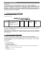
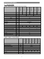
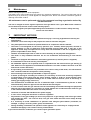
NAOS K4
Manual for boiler operation and installation
GB_2014_24
Table of Contents
page
General Information
1.
Produced Versions of the Boilers ............................................................................................................ 4
2.
Boiler Application and Benefits................................................................................................................ 4
3.
Technical Data......................................................................................................................................... 5
4.
Boiler Description .................................................................................................................................... 7
4.1
Boiler Design ...................................................................................................................................... 7
4.2
Control Features ................................................................................................................................. 7
4.3
Main Boiler Parts ................................................................................................................................ 9
4.4
A diagram showing flue gas flow in the exchanger .......................................................................... 11
4.5
Delivery and Accessory .................................................................................................................... 12
4.5
Instructions before Putting into Operation ........................................................................................ 12
User
5.
Boiler Attendance by the User............................................................................................................... 13
5.1
Description of the control functions .................................................................................................. 13
5.1.1
Activation of the boiler ................................................................................................................ 13
5.1.2
Values shown on the boiler screen ............................................................................................ 14
5.2
INFO mod ......................................................................................................................................... 15
5.3
Parameter setting ............................................................................................................................. 16
5.3.1
Setting the hot water temperature ............................................................................................. 17
5.3.2
Setting the temperature of water to the heating system ............................................................ 17
5.3.3
The SUMMER/WINTER switch (version K4G2S24XX and K4G3S24XX) ................................ 18
5.3.4
Temporary activation ................................................................................................................. 18
5.3.5
Setting the anti-cycling period (PR10) ....................................................................................... 19
5.3.6
Setting the pump rundown (PR11) ............................................................................................ 20
5.3.7
Setting the heating curve K-factor (PR15) ................................................................................. 21
5.3.8
Shifting of the heating curve (Opentherm) ................................................................................. 22
5.3.9
The „***“ (tri star) mode for hot water preheating....................................................................... 23
5.4
Failures ...................................................................................................................................... 24
5.4.1
Failures shown on the boiler screen .......................................................................................... 24
6.
Maintenance .......................................................................................................................................... 25
7.
IMPORTANT NOTICES ........................................................................................................................ 25
8.
Instructions for Product Disposal After Its Service Life ......................................................................... 26
9.
Warranty and Liability for Defects ......................................................................................................... 26
2
General Information
Servicing
10.
Placement and Installation .................................................................................................................... 27
10.1
Standards and regulations ............................................................................................................... 27
10.2
Possible Placement .......................................................................................................................... 28
10.3
Boiler Installation .............................................................................................................................. 29
10.4
Connecting to the Heating System and Water Filling ...................................................................... 31
10.5
Gas Connection................................................................................................................................ 31
10.6
Electric Power Supply Connection ................................................................................................... 31
10.7
Condensate Discharge ..................................................................................................................... 31
10.8
Flue Gas Ducting.............................................................................................................................. 31
10.9
Boiler Electrical Wiring ..................................................................................................................... 32
11.
10.9.1
Main components of boiler electrical equipment........................................................................ 32
10.9.2
Connection of the higher-level regulation and external boiler sensors ...................................... 32
10.9.3
Connecting terminal ................................................................................................................... 33
10.9.4
Wiring of the sensors ................................................................................................................. 34
Flue Gas Ducting ................................................................................................................................... 37
11.1
Flue gas ducting – examples of correct connection of flue duct and air supply............................... 39
11.2
Flue gas ducting – examples of incorrect connection of flue duct and air supply ............................ 39
11.3
STARR D80 and FLEX 80 system connection ................................................................................ 39
11.3.1
STARR, 2 x D 80 mm flue ducting diagram ............................................................................... 40
11.3.2
FLEX, 2 x D 80 mm flue ducting diagram .................................................................................. 41
11.4
LIK 60/100, 80/125 system connection ............................................................................................ 42
11.4.1
Diagram for flue gas ducting of the LIK type, version 60/100 mm (max. length 5 m),
or 80/120 .................................................................................................................................... 43
11.5
12.
Pressure Losses of Chimney Flue Elements in Case of NAOS K4 Boiler Usage ........................... 44
Commissioning ...................................................................................................................................... 45
12.1
Instructions before Putting into Operation ........................................................................................ 46
12.2
Boiler Setting .................................................................................................................................... 47
12.3
Conversion to a different type of fuel ............................................................................................... 49
12.4
Boiler Electronics Setting ................................................................................................................. 50
13.
Servicing Inspection of the Boiler .......................................................................................................... 52
3
General Information
Dear Customer
Thank you for your purchase of the NAOS K4 boiler and for your confidence in VIADRUS a.s.
To become familiar with a proper operation of your new product since the beginning, please read
carefully the presented user´s manual, especially Chapter No. 5 – Boiler Attendance by the user,
Chapter No. 6 – Maintenance, and Chapter No. 7 – IMPORTANT NOTICES. We ask you to follow the
information presented below and especially to perform the prescribed annual inspections to be
performed by an authorized specialized company, which guarantees a long-term boiler operation free
of failures to both your and our satisfaction.
1.
Produced Versions of the Boilers
In your order specify the following:
Order specification code:
NAOS K4 X X X XX X X
Exchanger:
G: stainless
Sermeta
Water heating:
1: without installed three-way
valve with a pump
2: three-way valve, pump, HSW
exchanger
3: with a three-way valve with a
pump
Electrical
equipment:
S: SIT
Output:
24: 24 kW
Fuel:
Z: natural gas
P: propane
Cover color:
W: white
R: red
S: silver
B: black
Conversion of the NAOS K4 boiler from natural gas to propane and vice-versa can be performed by a
contracted service provider only.
Chimney flue made by ALMEVA has been certified for this boiler. If you use chimney flue made by a
different producer, it is necessary to use a system with identical parameters as for the certified type
of the chimney flue.
2.
Boiler Application and Benefits
The NAOS K4 condensing boiler has been designed for combustion of low pressure natural gas.
The size of the condensing boiler is suitable for heating of family houses and recreational facilities as well as
for reconstruction of heat sources in individual apartment units. The condensation heat output is 5 – 24 kW.
The boiler body efficiency at the 50/30 °C temperature gradient varies in a range of 101 – 105 % depending
on the required output.
Boiler Benefits:
•
•
•
•
•
•
•
•
Low gas consumption
High combustion efficiency
Smooth output modulation
Easy attendance and maintenance
The boiler enables connecting to a reservoir of hot service water heater and ensures its preferential
heating
Reliability of the regulation and safety components
Low weight
Equithermal boiler regulation
4
General Information
3.
Technical Data
[kg]
[l]
[mm]
[mm]
[mm]
[mm]
[mm]
[bar]
[bar]
[-]
26
2
K4G3S24PX
ZP
Propane
I2H I2E
I3P
C13,C33, C43, C53, C83
27.5
3
460
320
720
80
80, 60
3
5
See diagram 1
[°C]
[°C]
[°C]
[mbar]
[dB]
K4G2S24PX
Propane
I3P
K4G2S24ZX
ZP
I2H I2E
K4G3S24ZX
[-]
[-]
K4G1S24PX
Fuel type
Category of appliance
Version
Weight
Water volume
Boiler dimensions – width
– depth
– height
Ø of combustion air connection
Ø flue gas socket
Working water overpressure
Testing water overpressure
Pressure loss
Maximum permitted working
temperature
Heating water setting range
Hot water setting range
Connecting overpressure of fuel
Noise level
Boiler connection
- heating water output
- heating water input to the heater
- return heating water input
- return water input from the heater
- condensate outlet
- safety valve output
- gas inlet
Connecting voltage
El. power input including pump
El. covering
K4G1S24ZX
Tab. No. 1 Sizes, operation temperature and electrical variables
ZP
I2H I2E
Propane
I3P
26.5
2
85
25 - 85
35 - 65
20
37
20
35 - 65
37
20
37
< 50
[Js]
[Js]
[Js]
[Js]
[mm]
[mm]
[Js]
¾“
½“
¾“
½“
Ø 25
Ø 21,2
3/4“
1/N/PE 230VAC 50 Hz, TN-S
110
40
-
[W]
IP
½“
¾“
Boiler output range
Nominal output 80/60 °C
Nominal output 50/30 °C
Minimum output 50/30 °C
Maximum nominal heat input
Minimum nominal heat input
HSW flow with ∆T 38 °C
Boiler efficiency at the nominal output 80/60°C
Boiler efficiency at the nominal output 50/30°C
Volume flow rate of fuel
Mass flow rate of flue gas
Nox class
Flue gas temperature (max.)
[kW]
[kW]
[kW]
[kW]
[kW]
[kW]
-1
[l.min ]
[%]
[%]
3 -1
[m .h ]
-1
[kg.h ]
[-]
[°C]
5
-
0.5-2.4
0.2-0.9
5 - 24
22,2
P=24
P=5
Q=22.8
Q=4.6
8,3
Up to 98
Up to 105
0.5-2.4 0.2-0.9
8 - 45
5
85
K4G3S24PX
K4G3S24ZX
K4G2S24PX
K4G2S24ZX
K4G1S24ZX
K4G1S24PX
Tab. No. 2 Thermal – technical parameters
comparison conditions 15 °C and 101.325 kPa, dry gas
-
0.5-2.4
0.2-0.9
Utilisable Overpressure for Heating System [kPa]
General Information
Volume Flow through of Heat Transfer Media, Water [litters per an hour]
Diagram no. 1 A diagram of the boiler heating circuit hydraulic loss
If the central heating system is fitted by thermostatic valves, it is necessary in order that their correct function
was ensured and noisiness was restrained. For usual installations when the C.H. system is connected on the
boiler, it is necessary to keep the dynamic overpressure in the system at the value of
8 - 15 kPa (0.8 - 1.5 m column of H2O). For this purpose a pressure relief valve must be fitted (e.g. Heimeier
HYDROLUX DN 20) in the system. It will be set on the required value of the pressure. The pressure relief
valve is usually fitted next to the boiler.
If the heating system is in a large distance from the boiler, the pressure relief valve may be placed at the
place of the system branching with advantage. The pressure relief valve ensures also the required minimal
flow through in the boiler in a case of radiator valves closing.
Values of the maximal overpressure have been also stated in the graph. They are intended for the individual
adjustments of power output grades of the circulating pump that is available in the heating system. Minimal
flow through the boiler drum is 500 l / hour. From the graph, it follows that the required flow through won't be
reached by exceeding of the maximal dynamic overpressure.
Fig. no. 1
The main boiler dimensions
6
General Information
4.
Boiler Description
4.1
Boiler Design
The boiler elementary structure consists in a condensing exchanger made of stainless steel pipes. It is
checked for tightness by test overpressure 5 bar. The boiler is further equipped with a premix burner. The
combustion mixture is mixed in a mixer in the preset air-gas ratio within the entire output range. Air is
supplied to the mixer by a modulation fan.
The boiler is made in three versions:
NAOS K4G1S24XX
NAOS K4G2S24XX
NAOS K4G3S24XX
version designed for heating only is equipped with a circulation pump
version with a circulation pump and flow type hot water (hereafter referred to as
“HSW”) heater
version with a circulation pump and a three-way valve ready to be used in
combination with a reservoir type hot water heater
The SIT automatics is an electronic control and ignition automatics designed for gas-fired central heating
boilers with a modulated fan and burner with preliminary mixing.
The combustion air inlet and the flue gas outlet may be implemented by several means as follows:
-
to the chimney,
through the wall,
through the roof (either inclined or horizontal),
to a joint shaft.
The boiler is an appliance in version C, i.e., a closed appliance with electronic ignition and flame ionization.
4.2
1
2
3
Control Features
electronic panel with the control panel
circulation pump output setting switch
valve for adding water to the heating system
Fig. no. 2
The NAOS K4 boiler control panel
7
General Information
•
Remove the bolts (1)
•
Remove the binding strip (2)
•
Pulling the cover side detach the Velcro strip (3)
Fig. no. 3
•
Remove the front cover
Removing the boiler front cover
8
General Information
4.3
1
2
3
4
5
6
7
8
9
10
Main Boiler Parts
11
12
13
14
15
16
17
18
19
20
21
22
23
three-way valve (only for versions
K4G2S24XX and K4G3S24XX)
HSW temperature sensor (only for version
K4G2S24XX)
HSW exchanger (only for version
K4G2S24XX)
gas valve
siphon
safety valve
circulation pump
gas supply pipe
bleeder valve
boiler electronics
Fig. no. 4
burner plate
heating water temperature sensor
mixer
safety thermostat
ignition electrode
ionization electrode
boiler frame
exchanger
fan
expansion tank
name plate
boiler front cover
pressure gauge
The NAOS K4 boiler assembly (version shown - K4G2S24XX)
9
General Information
1
2
3
4
condensing exchanger
input of return water to the exchanger
pump
input of return water to the pump
5
6
7
8
heating system (radiators)
output of hot water from the exchanger
input of hot water to the radiators
filling valve
Fig. no. 5 NAOS K4G1S24XX with only water heating for the system
(hydraulic diagram of the version and the sketch of the hydro-block)
1
2
3
4
5
6
condensing exchanger
input of return water to the exchanger
pump
input of return water to the pump
heating system (radiators)
output of hot water from the exchanger
7
8
9
10
11
input of hot water to the radiators
three-way valve
flow type water heater
input of water to the flow type water heater
output of water from the flow type water
heater
Fig. no. 6 NAOS K4G2S24XX with a flow type heater
(hydraulic diagram of the version and the sketch of the hydro-block)
10
General Information
1
2
3
4
5
6
7
condensing exchanger
input of return water to the exchanger
pump
input of return water to the pump
heating system (radiators)
output of hot water from the exchanger
input of hot water to the radiators
8
9
10
11
12
13
14
three-way valve
filling valve
output of hot water from the heater
refilling of water to the system
reservoir type water heater
relief valve of the heater
input of water to the heater
Fig. no. 7 NAOS K4G3S24XX the boiler version
(hydraulic diagram of the version and the sketch of the hydro-block)
4.4
A diagram showing flue gas flow in the exchanger
first heat exchange
water output
50°C
water input
30°C
water input
water output
flue gas after
water
condensation
burner
40 °C
condensation partition
condensate
condensate outlet
flue gas after the first heat exchange
flue gas after the second heat exchange
gorące
hot
fluespaliny
gas
gazu
Fig. no. 8
A diagram showing flue gas flow in the exchanger
11
General Information
4.5
Delivery and Accessory
The NAOS K4 boiler is delivered as assembled on a pallet, packed in a carton cover. Flue gas ducting is
delivered in accordance with the customer requirements based on the actual connection of air inlet and flue
gas outlet (see chapter 11).
Standard accessory for all boiler versions:
Mounting bracket
1 pcs
Dowel - 8 x 40 mm
5 pcs
Bolt - 5 x 40
5 pcs
Chimney opening reducer piece
1 pcs
External sensor PL10K
1 pcs
Blinding plug D80
1 pcs
Operation and installation manual, including the warranty certificate
A list of contracted servicing organizations
For version NAOS K4G3S24XX (hot water exchanger):
sensor QAZ 36.526/109
1 pcs
Recommended accessory for all boiler versions:
Room thermostat
1 pcs
ALMEVA flue gas ducting, Type: LIK, STAR or FLEX
Water filter
Opentherm (Honeywell CR 04)
The recommended accessory is not included in the boiler standard price.
4.5
Instructions before Putting into Operation
The boiler can only be commissioned by organizations that are authorized and trained for this
purpose by the manufacturer.
The installation shall comply with the regulations that are applicable for this equipment. The boiler shall be
compatible with the local connecting conditions (checking the parameters of the boiler with the information on
the name plate).
During the first start of operation of the boiler it is necessary to instruct the user in accordance with
this manual and to hand over this manual to the user.
Then it is necessary to perform:
inspection revision before commissioning,
inspection for any water leakages,
inspection of instrumentation and safety controls.
Notice:
The ABS boiler cover is protected by a protection foil. This foil needs to be removed before commissioning of
the boiler or 1 month from unpacking the boiler from the packaging carton at the latest. Removing the foil
after this period may be more difficult.
12
User
5.
Boiler Attendance by the User
Description of the control panel
1
4
2
5
3
6
1
2
3
4
5
+ HSW temperature up
- HSW temperature down
+ heating water temperature up
- heating water temperature down
Switch, switchover summer/winter,
RESET, confirmation of selection
1
2
3
flame indication
call the servicing engineer
boiler may be unlocked by
pressing the RESET button
(switch)
parameter setting
Hot Water mode
heating water mode
4
5
6
Parameters shown on the boiler screen. Basic summary:
Legend for description of the functions:
This symbol indicates the necessity of
restarting the boiler by the user by the
„RESET“ button
This symbol indicates the necessity of
a repair by a servicing organization
Graphic display of a flashing symbol
5.1
Description of the control functions
The symbols and values shown on the screen are described below. The basic information shown on the
screen is the heating circuit temperature – in case of hot water heating it is the temperature measured on the
hot water sensor.
Setting the required temperature of hot water and system water temperature is performed by using buttons
1 - 4 on the boiler control panel.
When the higher level regulation is used, this option is blocked on the boiler and temperatures can be set
using the room instrument only.
5.1.1 Activation of the boiler
The boiler is energized even after turning off and the electronics ensures anti-freezing protection and (if set)
also short operation of the circulation pump in regular intervals to prevent freezing.
13
User
Screen
Description
Stand-by mode
To turn on the boiler press down the main switch
button (5) and hold it for some time.
For switching the boiler to the summer mode see
chapter 5.3.3
To turn off the boiler press down the main switch
button (5) and hold it for some time (5 sec).
5.1.2 Values shown on the boiler screen
Screen
Description
Screen
When controlled by the
thermostat, the thermostat
is open
Boiler in the summer
mode, the primary circuit
temperature is shown
Description
Requirement for refilling of
water to the heating system.
The FL symbol is shown in
the 1s intervals.
Preheating of the hot water
circuit. Shown only when
this function is active.
Boiler in the winter mode,
the primary circuit
temperature is shown
HSW heating, current
HSW temperature is
shown
Heating water heating,
current temperature is
shown
Accident protection active,
bP+temperature flashing
Heating water temperature
setting (other symbols not
shown)
Higher level regulation
connected
(4 s interval)
Ignition of the burner
Burner in operation
HSW temperature setting,
(other symbols not shown)
Boiler is off, anti-freezing
function is active
Pump rundown
Ignition of the burner is
postponed due to the
system settings
“Chimney-sweeper” function
LP = output HSW MIN
hP = output MIN
cP = output MAX
dP = output HSW MAX
(setting parameters P09=01)
Indicator of the servicing
inspection requirement.
14
User
5.2
INFO mod
Information messages shown on the screen that are used for checking the boiler parameters.
Screen
Multiplier,
units
Description
For entering the Info Mode press down button 3 and 5
simultaneously and hold them down for 5 s
Scrolling in the Info Menu by the + and – buttons
d0
Not used
Outside temperature (temperature measured by the
outside sensor B9 – if connected)
d1
°C
d2
x 0.1
K-factor
d3
x 0.1
Offset of the heating curve (K-factor) – (see diagram no.
3)
d4
°C
Temperature computed on the basis of the outside
sensor
d5
°C
Water output temperature
d6
°C
Return water temperature
(not shown for the NAOS boiler in the SIT version)
d7
°C
Actual temperature HW
d8
°C
Flue gas temperature
d9
x 100, rpm
Fan revolutions (Ex.: 44x100=4400)
dc
Software version: - burner control
dd
Software version: –the main board
de - c9
Not used
For exiting the Info Mode press down button 3 and 5
simultaneously.
15
User
5.3
Parameter setting
The boiler control varies depending on connecting the boiler to the heating system
Boiler (terminal) wiring
diagram)
Description
Hot water
Heating
water
Setting the hot and
heating water
temperature
Boiler without
the room device
and without the
outside sensor.
Boiler control panel
Boiler without
the outside
sensor, room
thermostat
connected.
Boiler control panel
Boiler without
the outside
sensor,
OPENTHERM
room device
with
communication
connected.
Room device
Water temperature to the
system is computed
based on the outside
temperature and setting
of the heating curve
K-factor. For changing the
values see chapter 5.3.7
and 5.3.8.
Water temperature to the
system is computed
based on the outside
temperature and setting
of the heating curve
K-factor. For changing the
values see chapter 5.3.7
and 5.3.8.
Water temperature to the
system is computed
based on the outside
temperature and setting
of the heating curve
K-factor. For changing the
values see chapter 5.3.7
and 5.3.8. Changing the
hot water temperature by
the room device only.
Boiler without
the room
device, the
outside sensor
connected.
Boiler with the
outside sensor
and the room
thermostat
connected.
Boiler with the
outside sensor
and
OPENTHERM
room device
with
communication
16
User
5.3.1 Setting the hot water temperature
When the OPENTHERM higher-level regulation is connected, the screen shows the current temperature.
Changing the hot water temperature setting is done by the room device.
Screen
or
Description
Change the temperature setting when the boiler is turned on.
Set the desired temperature using button 3 or 4.
The temperature can be set with a range of 30 – 60 °C.
When you press button 3 or 4 for the first time the screen will show the
current temperature setting and the faucet symbol on the screen will be
flashing.
When the parameters are not changed within 5 s the current temperature
setting will be stored and the boiler will switch to the normal mode.
5.3.2 Setting the temperature of water to the heating system
When the OPENTHERM higher-level regulation is connected, the screen shows the current temperature.
Changing the hot water temperature setting is done by the room device.
When the outside sensor is connected, the temperature of water to the heating system is computed based
on the outside temperature.
Screen
Description
Change the temperature setting when the boiler is turned on.
Set the desired temperature using button 3 or 4.
The temperature can be set with a range of 25 – 85 °C.
When you press button 3 or 4 for the first time the screen will show the
current temperature setting and the radiator symbol on the screen will be
flashing.
When the parameters are not changed within 5 s the current temperature
setting will be stored and the boiler will switch to the normal mode
17
User
5.3.3 The SUMMER/WINTER switch (version K4G2S24XX and K4G3S24XX)
Setting the boiler for summer and winter operation. When the boiler is switched to the summer mode the
requirement for heating of water to the system is ignored.
Screen
Description
Stand-by mode.
To activate the boiler by press down the main switch button (5)
and hold it for some time. The boiler will start operation in the
winter mode.
For switching to the summer mode press down the main switch
button (5) and hold it for 2 s.
Winter mode
Summer mode
5.3.4 Temporary activation
Temporary activation of the boiler for heating of water to the heating system – only when the system
is equipped by the outside sensor.
This setting is used to force the boiler to heat water to the heating system. The boiler will be in operation for
a period not longer than 24 h or until switching back to the normal mode.
Screen
Description
Change the mode setting when the boiler is turned on
or
Press down buttons 3 and 4 simultaneously
/
/
The mode is activated
The value of the output temperature to the heating system
To deactivate this mode press down buttons 3 and 4
simultaneously
/
The system is deactivated
18
User
5.3.5 Setting the anti-cycling period (PR10)
This parameter is used to prevent frequent starting of the boiler to the heating system. This is the minimum
period of time for which the requirement for heating to the system will be ignored. The default setting is 3
min.
This value does not have any impact on executing the requirement for starting the boiler in case of a
requirement for heating of hot water.
The setting range is 0 – 600 s. The shown value needs to be multiplied by 6, i.e., 10 x 6 = 60 s
Screen
Button
pressing
time
Description
Switching to the servicing mode shall be done when the
boiler is turned on
or
10 s
Switch the boiler to the parameter setting mode by
simultaneous pressing of buttons 3, 4 and 5 for a period of
10 s
The screen will show PR / 01
/
Set the required parameter on the screen using button
3 or 4
Set the parameter PR / 10 on the screen using button 3 or 4
/
2s
Switch the boiler to the value setting mode by simultaneous
pressing of buttons 3 and 5 for a period of approx. 2 s .
The default setting for anti-cycling period is 3 min.
The setting range is 0 – 600 s. The shown value needs to
be multiplied by 6, i.e., 10 x 6 = 60 s
For switching back without changing the parameters
simultaneously press down buttons 4 and 5.
Press
shortly
To confirm the set value press shortly button 5 on the main
switch
10 s
To exit the setting mode simultaneously press down buttons
3, 4 and 5 for 10 s
19
User
5.3.6 Setting the pump rundown (PR11)
This parameter is used to set the pump rundown. The default setting for the rundown is 1 min.
The setting range is 0 – 600 s. The shown value needs to be multiplied by 6, i.e., 10 x 6 = 60 s.
Screen
Button
pressing
time
Description
Switching to the servicing mode shall be done when
the boiler is turned on
or
10 s
Switch the boiler to the parameter setting mode by
simultaneous pressing of buttons 3, 4 and 5 for a
period of 10 s
The screen will show PR / 01
/
Set the required parameter on the screen using
button 3 or 4
Set the parameter PR / 11 using button 3 or 4
/
2s
Switch the boiler to the value setting mode by
simultaneous pressing of buttons 3 and 5 for a period
of approx. 2 s.
The default setting for rundown period is 1 min.
The setting range is 0 – 600 s. The shown value
needs to be multiplied by 6, i.e., 10 x 6 = 60 s
For switching back without changing the parameters
simultaneously press down buttons 4 and 5.
Press
shortly
10 s
To confirm the set value press shortly button 5 on the
main switch
To exit the setting mode simultaneously press down
buttons 3, 4 and 5 for 10 s
20
User
5.3.7 Setting the heating curve K-factor (PR15)
When the outside sensor is connected to the boiler the temperature of water to the heating system is
computed on the basis of the outside temperature and the value of the set K-factor
°C
°C
°C
°C
Diagram no. 2 Heating curves for a boiler without
connected room device
Diagram no. 3 Heating curves for a boiler with
connected room device (OPENTHERM)
Screen
Button
pressing
time
Description
Switching to the servicing mode shall be done when
the boiler is turned on
or
10 s
Switch the boiler to the parameter setting mode by
simultaneous pressing of buttons 3, 4 and 5 for a
period of 10 s
The screen will show PR / 01
/
Set the required parameter on the screen using
button 3 or 4
Set the parameter PR / 15 using button 3 or 4
/
2s
Switch the boiler to the value setting mode by
simultaneous pressing of buttons 3 and 5 for a period
of approx. 2 s.
Using buttons 3 or 4 set the value of the required
K-factor on the screen.
21
User
Button
pressing
time
Screen
Description
For switching back without changing the parameters
simultaneously press down buttons 4 and 5.
Press
shortly
10 s
To confirm the set value press shortly button 5 on the
main switch
To exit the setting mode simultaneously press down
buttons 3, 4 and 5 for 10 s
5.3.8 Shifting of the heating curve (Opentherm)
Shifting of the heating water output temperatures. While the K-factor will set the slope of the heating curve,
shifting of the heating curve will increase or reduce the heating water output temperature within the entire
regulation range by the set value. The set value is in °C. The maximum setting range is - 15°C to + 15°C.
Screen
Unit
Description
Switching is done when the boiler is turned on
or
°C
Using buttons 3 and 4 set the value of the required
heating curve shift on the screen
°C
°C
Diagram no. 4 Shifting of the heating curve
22
User
5.3.9 The „***“ (tri star) mode for hot water preheating
This is used to accelerate the start of hot water heating on the versions that are equipped with a flow-type
heater. (K4G2S24XX), during operation the boiler is kept at an increased temperature so that the time
necessary for hot water heating is reduced to minimum. In certain situations the „***“ mode may increase
gas consumption.
Screen
Description
Switching is done when the boiler is turned on
or
Simultaneously press down button 1 and 2
/
The „***“ preheating system is activated
Simultaneously press down button 1 and 2 to deactivate the
system
/
The „***“ preheating system is deactivated
23
User
5.4
Failures
5.4.1 Failures shown on the boiler screen
The boiler is equipped by diagnostics for troubleshooting. The description of errors is stated further
in the tables. Failures might be divided into 3 categories:
• Failures which do not require resetting and after their correction, the automatics will switch
over to operational state without operators’ action;
• Failures which require operators’ action after their correction (short pressing of the main I/O
switch);
• Failures which might be corrected by authorised service only.
Display
Description
Display
Blocking – unsuccessful
igniting of the boiler
Description
Blocking of the flue gas
temperature sensor due to high
temperature of the flue gas
(120 °C)
Blocking – switching safety
thermostat off
Failure of flame indication
(symbol is flashing)
Blocking – unspecified
failure
Failure of NTC sensor of return
water (not used)
Pump failure or low
pressure in system
Temperatures difference
higher than 40 °C
Failure of fan revolutions
control
Blocking – pump failure or
temperature reached more
than 105°C
Failure of NTC sensor of
heating water
Temperature increment
overreached the limit (>2 °C/s)
Failure of NTC sensor of
HW
Failure of NTC sensor of HW
inlet (if it is installed)
Failure of external sensor
Failure of boiler electric
connection
Interruption of the flue gas
sensor line
Limitation of NTC sensor
during HW heating up
24
User
6.
Maintenance
Before cleaning always turn off the equipment.
The plastic cover of the product does not require any extensive maintenance. The cover of the boiler can be
wiped off by a dry cloth or by a cloth dipped in a detergent lotion. Never use solvents or abrasive agents for
cleaning of the boiler surface.
All maintenance can be performed only by the contracted servicing organization trained by
the manufacturer.
The user is obliged to ensure regular inspection of the gas boiler once a year. When these conditions
are not observed, the user cannot claim warranty repairs.
Use only original spare parts approved by the manufacturer in order to ensure safety and long
service life of the boiler.
7.
IMPORTANT NOTICES
Boiler installation and setting can be performed only by a servicing organization trained by the
manufacturer.
The boiler can be used only for the purpose for which it has been designed.
Only adult persons are allowed to operate the boiler in compliance with this manual.
The boiler is not designed for the use by persons (incl. children) whose physical, sensual or
mental disability or lack of experience and knowledge prevent them from a safe use of the
appliance unless they are supervised or if they were not instructed on the use of appliance by a
person responsible for their safety.
Children should be supervised in order to ensure that they do not play with the appliance.
The boiler is fully automatic therefore we do not recommend disconnecting it from electric
power.
The boiler is equipped with automatic anti-freezing protection (if electric power is supplied).
It is forbidden to intervene with any secured parts.
No flammable objects can be placed, built or suspended near the boiler and flue gas ducting (a
safe distance of the appliance from flammable materials in the main radiation direction is 50 mm
and 10 mm in other directions).
If any building reconstructions are performed in the close vicinity of the boiler, turn off the boiler
with a sufficient lead time and protect it from polluting.
Avoid cleaning of the boiler by flammable or explosive agents.
In winter (if leaving for a holiday, for instance) it is necessary to ensure the necessary inspection
of functionality of the boiler and the entire heating system in order to avoid possible water
freezing resulting in equipment damage due to some external reasons (such as electricity or
heating gas supply outage, and so on).
The manufacturer recommends the use of antifreeze Alphi 11 manufactured by Fernox or X500
manufactured by Sentinel approved for the Sermet heat exchangers.
In case of boilers with flue gas exhaust into the surrounding environment through the peripheral
external wall of the building it is necessary to check whether the condensed water from flue gas
in the exhaust basket does not freeze in a frosty weather.
The boiler is fed with 230 V/50 Hz electric power supply.
In case of fire, extinguish the boilers as electric equipment.
Pay attention to any gas leakage (in case of any suspicion of gas leakage, shut off the gas intake
and ventilate the area - call a service firm). The gas valve under the boiler must always be kept
freely accessible.
It is necessary to avoid combustion air pollution with halogen hydrocarbons (contained, for
example, in sprays, solvents, paints, glues) and with dust.
During assembly, installation and operation of the appliance it is necessary to comply with the
standards that apply in the relevant country of destination.
If you fail to meet these conditions you cannot require guarantee repairs.
25
User
8.
Instructions for Product Disposal After Its Service Life
VIADRUS a.s. is a contractual partner of EKO–KOM a.s., its client number being EK – F00060715
Packaging is in compliance with EN 13427.
We recommend disposing the packaging in the following way:
plastic foils, carton cover, use the Scrap Materials
metal binding strip, use the Scrap Materials
the wood base is intended for single using and it cannot be further reused. Its disposal is subjected to
Act No. 477/2001 Coll. and 185/2001 Coll. as amended.
We recommend disposing the individual boiler parts as follows:
exchanger, use the Scrap Materials
pipe distributions, use the Scrap Materials
other metal parts, use the Scrap Materials
boiler frame insulation material, through a contractor dealing with waste collection and disposal
Upon losing the utility value of the product, it is possible to return the product back (if applicable), in
case the originator states it is waste, the waste should be disposed according to the provisions of
the effective legislation in the particular country.
9.
Warranty and Liability for Defects
VIADRUS SpA provides an extended warranty on the NAOS boilers for 72 months from the date of
putting into operation and a maximum of 76 months from the date of shipment from the
VIADRUS a.s.
Within this warranty the manufacturer agrees to remove the defects of the product in the form of a
repair free of charge.
In order to recognize the warranty the manufacturer requires:
- commissioning of the NAOS condensing gas boiler by an authorized servicing organization
contracted by the manufacturer. The contracted servicing organization is obliged to send a
notification on commissioning of the NAOS condensing gas boiler in writing to the manufacturer
not later than 20 days upon commissioning to the following address: VIADRUS a.s., Bohumín,
Bezručova 300;
- in accordance with act no. 458/2000 Coll. “on the Conditions for Doing Business and Exercising
State Administration in the Energy Sectors and amending certain acts (the Energy Act) and
ČSN 38 6405 change 1 5/99, EN 1775 to inspect the gas boiler on a regular basis once a year. The
inspections can be performed only by an organization (contacted servicing organization)
authorized by the manufacturer, i.e., by VIADRUS a.s. The contacted servicing organization is
obliged to record and document all records on the implemented warranty and after-warranty
repairs and on the execution of the regular annual inspections of the boiler in the annexure to the
warranty sheet in this manual.
Each defect shall be reported immediately after its detection, always by phone as well as in a written
form.
A failure to meet the specified instructions shall result in cancellation of the warranty by the
manufacturer.
The warranty does not apply to:
•
defects caused by improper assembly and improper attendance of the product and defects
caused by improper maintenance, see chap. 6;
•
defects and damages caused by failure to observe water quality in the heating system, see chap.
no. 10.1 and 10.4;
•
defects caused by failure to observe the instructions specified in this manual;
•
product damage in the course of transport or another mechanical damage;
•
defects caused by unsuitable storage (for example water);
•
consumables, i.e. electrodes, water/gas seal and fuses.
•
defects caused by natural disasters or force majeure.
The manufacturer reserves the right for changes performed within the product innovation process
which are not necessarily contained in this manual.
26
Servicing
10.
Placement and Installation
10.1 Standards and regulations
The heating system shall be filled with water meeting the requirements of ČSN 07 7401 and
especially the water hardness shall not exceed the required parameters.
Hardness
2+
Ca
Concentration of total Fe + Mn
*) recommended value
a) to the heating system
ČSN 06 0310
ČSN 06 0830
ČSN 07 7401
EN 15502-2-1
EN 677
b) to the chimney
ČSN 73 4201
Recommended values
mmol/l
mmol/l
mg/l
1
0,3
(0.3)*
Heating systems in buildings – Designing and installation
Heating systems in buildings – protecting device
Water and steam for thermal energy equipments with working pressure
up to 8 MPa.
Gas-fired central heating boilers. Specific standard for type C appliances and
type B2, B3 and B5 appliances of a nominal heat input not exceeding 1 000 kW
Gas – fired central heating boilers – Specific requirements for condensing
boilers with a nominal heat input not exceeding 70 kW
Chimneys and flue gas ducting– designing, implementation and connection of
fuel consumers.
c) regarding the fire regulations
ČSN 06 1008
Fire safety of heat installations.
EN 13501-1 +A1
Fire classification of construction products and building elements – Part 1:
Classification using test data from reaction to fire tests
d) to the system of HWS heating
ČSN 06 0320
Heating systems in buildings – Hot water preparation – Designing and planning
ČSN 06 0830
Heating systems in buildings – Safety devices.
ČSN 75 5409
Water installations inside buildings.
e) regarding the electric network
CSN 33 0165
Electrical regulations. Identification of conductors by colours or numerals.
Procedure provisions
ČSN 33 1500
Electrical regulations; revision of electrical equipments
ČSN 33 2000-1 ed. 2
Low-voltage electrical installations – Part 1: Fundamental principles,
assessment of general characteristics, definitions.
ČSN 33 2000-4-41 ed. 2
Low voltage electrical installations - Part 4- 41: Protection for safety - Protection
against electric shock
ČSN 33 2000-5-51 ed. 3
Electrical installations of buildings – Part 5-51: Selection and erection of
electrical equipment – Common rules
ČSN 33 2000-7-703 ed.2
Electrical installations in buildings - Part 7-703: Single-purpose equipment and
equipment in special buildings - Rooms and cabins with sauna stoves.
ČSN 33 2130 ed. 2
Low-voltage electrical installations – Internal electric distribution lines
ČSN 33 2180
Electrical regulations: Connection of electric instruments and appliances
ČSN 34 0350 ed. 2
Safety requirements for flexibile cords and cables
EN 60079-10-1
Explosive atmospheres — Part 10-1: Classification of areas — Explosive gas
atmospheres
EN 60079-14 ed.3
Explosive atmospheres - Part 14: Electrical installations design, selection and
erection
EN 60252-1 ed. 2
Capacitors for AC motors – Part 1: In general – Design, testing, dimensioning –
Safety requirements – Instructions for installation and operation.
EN 60 335-1 ed.2
Electric appliances for household and similar purposes – Safety – Part 1:
General requirements
EN 60 335-2-102
Electric appliances for household and similar purposes – Safety – Part 2-102:
Special demands on appliances containing the electric connections and burning
the gas, oil and solid fuels
EN 60445 ed. 4
Basic and safety principles for man-machine interface, marking and
identification – Identification of equipment terminals, conductor terminations and
conductors
27
Servicing
f) to the gas distribution
EN 1775
EN 12007-1
EN 12007-2
EN 12007-3
EN 12007-4
ČSN 07 0703
ČSN 38 6405
EN 15001-1
Act No. 458/2000 Coll.
Gas supply. Gas pipework for buildings. Maximum operating pressure less than
or equal to 5 bar. Functional recommendations
Gas supply systems - Pipelines for maximum operating pressure up to and
including 16 bar - Part 1: General functional recommendations
Gas supply systems - Pipelines for maximum operating pressure up to and
including 16 bar - Part 2: Specific functional recommendations for polyethylene
(MOP up to and including 10 bar)
Pipelines for maximum operating pressure up to and including 16 bar - Part 3:
Specific functional recommendations for steel
Gas supply systems - Pipelines for maximum operating pressure up to and
including 16 bar - Part 4: Specific functional recommendations for renovation
Boiler room with gas fuel –operated equipments
Gas equipments. Operating principles
Gas supply systems Pipelines for operating pressure greater than 0,5 bar for
industrial use and pipelines for operating pressure greater than 5 bar for
industrial and non-industrial use - Part 1: Detailed functional requirements for
design, materials, construction, inspection and testing
on Business Conditions and Public Administration in the Energy Sectors and on
amending certain acts (the Energy Act)
10.2 Possible Placement
The installation and operation of the boiler shall comply with all requirements of ČSN 06 1008.
The boiler placement shall comply with the project documentation. The flue gas exhaust shall comply with
the valid regulations. Ports of individual pipes for supply of combustion air and discharge of flue gases shall
be located in such a way that they are located inside a square with a side of 50cm by the boiler. The boiler
can be placed on a wall with ensured loading capacity only.
At least 0.2 m shall be left free beside the boiler and above the boiler and at least 1 m shall be left free in
front of the boiler for assembly and repairs. The manufacturer recommends placing these products in
closed heating systems.
The boiler also can be placed in a room with the basic environment according to ČSN EN 33 2000-1 ed 2.
Fig. no. 9
Main dimensions of the boiler
28
Servicing
Placement of the boiler with respect to fire regulations:
A safe distance from flammable materials:
−
−
−
when installing and operating the boiler it is necessary to keep a safe distance of 200 mm from the
materials of combustibility grade A1, A2, B and C (D);
for easily combustible materials of combustibility grade E (F), which quickly burn and burn themselves
even after removal of ignition source (such as paper, cardboard, asphalt and tar paper, wood and
woodfiber boards, plastics, floor coverings) the safe distance has to be doubled, i.e. to 400 mm;
safe distance should be doubled also where the grade of reaction to fire has not been proved.
A safe distance from surfaces of materials with individual degrees of flammability and information of the
flammability degree of common building materials, if necessary, for appliances which can be operated in the
immediate vicinity of walls made of flammable materials will be defined with the maximum permissible
temperatures of surface or wall temperature increase according to ČSN EN 13 501 – 1 + A1.
Grade of reaction to fire
Grade of reaction to fire
Examples of building materials and products included in the reaction to fire
(Extract from ČSN EN 13501-1 + A1)
granite, sandstone, concrete, bricks, ceramic tiles, mortars, fireproof plasters, …
A1 – incombustible
A2 – combustible with
acumin, izumin, heraklit, lignos, boards and basalt felt, fibreglass boards,...
difficulty
B – hardly combustible
Beech and oak wood, hobrex boards, plywood, werzalit, umakart, sirkolit,...
C
(D)
–
medium
Pinewood, larch, whitewood, chipboard and cork boards, rubber flooring,…
combustible
Asphaltboard, fibreboards, cellulose materials, polyurethane, polystyrene,
E (F) – easily combustible
polyethylene, PVC,…
10.3 Boiler Installation
Using the installation stencil (the stencil is printed at the bottom of the carton packaging of the boiler) attach
the enclosed bracket to the wall using 3 pieces of dowels with diameter of 8mm and bolts. Mount the NAOS
K4 boiler on the bracket and using the marked outlets the boiler is connected to the heating system incl. hot
water (if used) and gas distribution pipe according to Fig. no. 10. The connection of condensate outlet should
be in compliance with the effective valid ČSN and EN standards. Then the flue gas exhaust is connected
according to the project documentation. Remove the protection foil from the front cover.
Fig. no. 10 Mounting bracket, connecting dimensions
29
Servicing
NOTICE: The manufacturer recommends installing water filter to the heating system.
Fig. no. 11
1
2
3
4
5
… heating water outlet
…condensate outlet
…safety valve outlet
…gas inlet
…filling valve
7
8
…system water filling inlet
… heating water inlet
NAOS K4G1S24XX – Boiler connections, bottom view of the boiler
1
2
3
4
5
6
7
8
… heating water outlet
… condensate outlet
… hot water outlet
… safety valve outlet
… filling valve
… gas inlet
… hot water heating inlet
… heating water inlet
Fig. no. 12 NAOS K4G1S24XX –Connections of the boiler with a flow type heater, bottom view of the
boiler
1
2
3
4
5
6
7
8
9
… heating water outlet
… water inlet to the heater
… condensate outlet
… safety valve outlet
… gas inlet
… filling valve
… hot water heating inlet
… water inlet from the heater
… heating water inlet
Fig. no. 13 NAOS K4G1S24XX – Connections of the boiler with a reservoir type heater, bottom view
of the boiler
The expansion tank capacity is 10 liters. This volume is enough for approx. 150 l of water in the heating
system.
The system should be designed for a temperature gradient of 50/30 °C due to the use of condensation. The
condensing boiler can also be used for old gravitational systems that usually were overdesigned and thanks
to this fact condensation can be efficiently used even for this system but it is necessary to expand this
system with a corresponding expansion tank.
The condensing boiler is equipped with a Willo three-speed pump. Setting of the pump speed shall
correspond with the requirements of the heating system so that the hydraulic system is balanced.
Connecting to the HSW heating system and to the gas pipe is implemented through ball valves.
30
Servicing
10.4 Connecting to the Heating System and Water Filling
Water for filling the boiler and the heating system must be clear and colorless, with no suspended
substances, oil and chemically aggressive substances. The parameters of circulation and refilling water shall
meet:
The highest permissible heating water values according to ČSN 07 7401
Hardness
(mmol/l)
1
Ca2+
(mmol/l)
0.3
Concentration of total Fe + Mn
(mg/l)
(0.3)*
* a recommended value
When the water hardness does not meet the required parameters, it shall be treated accordingly. Several
times reheated water with a higher hardness does not prevent precipitation of salts on the walls of the boiler
body. The precipitation of limestone decreases the heat transfer from metal to water at the particular point by
10 %.
During the heating season it is necessary to keep a constant volume of heating water in the heating system
and be particular about bleeding the heating system. The water from the boiler and the heating system shall
never be discharged or taken for some other use except in cases of emergency like repairs etc. Draining of
the heating water and filling new water increases the danger of corrosion and scaling. If it is necessary to
refill water into the heating system, then add water only when the boiler is cold.
When adding water to the boiler, the system shall be disconnected from electric power supply. The bleeding
valve on the boiler and on the heating system shall be functional and open. Adjust the expansion reservoir to
a pressure which is higher by 10 kPa than the required pressure in the heating system. The system will be
pressurized to the required pressure of approx. 100 kPa and it will be vented again. We recommend using
the filter on the inlet to the heating system for water filling.
The heating system shall have a sufficient number of venting points. The lowest point of the heating system
shall be equipped with a drain valve.
10.5 Gas Connection
Prior to connecting the gas pipeline to the boiler, the gas pipeline shall be tested and subjected to revision
inspection. After connecting the boiler to gas pipeline, all gas connections shall be tested again by means of
a detector or foaming solution. The input pressure of natural gas shall correspond to the value in table no. 1.
10.6 Electric Power Supply Connection
The boiler is equipped with a flexible mains supply and a plug. According to ČSN EN 60 335–1 ed. 3
the boiler shall be placed in such a way that ensures that the plug is freely accessible.
A 230 V/50 Hz socket should be located beside the boiler within a distance of 1.5 m. The socket shall
correspond to the effective regulations and it shall be subjected to revision inspection.
10.7 Condensate Discharge
A built-in siphon (trap) serves as the condensate outlet. It must be connected to a sewerage overflow. Prior
to the commissioning of the boiler, it is necessary to check whether the condensate is being drained. The
size of a PVC drain pipe is Ø 16mm. The pH value of this condensate is < pH 3 and it can be discharged to
the sewerage.
The boiler condensate outlet shall be implemented in such a way that ensures that it does not prevent fluent
discharging of the condensate.
The boiler is equipped with an odor trap (siphon) that needs to be filled with approx. 100 ml of water before
starting of the boiler. Discharging of the condensate to the sewerage is governed by the national or regional
(local) regulations. The drain pipe inclination shall be at least 5° from the boiler to the sewerage and it shall
not be blocked in any way (when the condensate drain pipe is blocked, the boiler furnace will resonate).
10.8 Flue Gas Ducting
See chapter 11 - Flue Gas Ducting
31
Servicing
10.9 Boiler Electrical Wiring
10.9.1 Main components of boiler electrical equipment
THERMOSTA
T
Opentherm
thermostat
HSW sensor
(version 3)
10 kΩ
outlet water sensor
NORDGAS
TP01BH1REV
flue gas temperature
sensor
exchanger sensor
emergency
thermostat
ignition electrode
HSW sensor (version 2)
NORDGAS
TP02BH1IEV
watching electrode
Fan
NATALINI NG40
OTMA hydro-block versions
Version 2
Version 1
- pump: Wilo connector
- pump: Wilo connector
- pressure gauge sensor: - pressure gauge sensor:
2 x 6,3
2 × 6,3
- flow switch : 2 x 6,3
- three-way valve : 3 x 6,3
Gas valve
SIT
Version 3
- pump: Wilo connector
- pressure gauge sensor:
2 x 6,3
- three-way valve:
3 x 6,3…
Fig. no. 14
10.9.2 Connection of the higher-level regulation and external boiler sensors
Fig. no. 15
Terminal for a boiler
32
Servicing
10.9.3 Connecting terminal
Wiring of the connecting terminal for a boiler without higher-level regulation (standard delivery of the
boiler):
Power mains 230VAC
Room thermostat
Room instrument OPENTHERM
Fig. no. 16
Wiring of the room thermostat:
Power mains 230VAC
Room thermostat
Room instrument OPENTHERM
Fig. no. 17
Wiring of the higher-level regulation – regulator with OPENTHERM communication:
Power mains 230VAC
Room thermostat
Room instrument OPENTHERM
Fig. no. 18
33
Servicing
10.9.4 Wiring of the sensors
B9
-
wiring of the sensor depends on the type of the used room instrument the connection of which is
necessary for using the function of equithermal regulation
Hot water sensor B3 is used only for version K4G3S24XX (reservoir).
Hot water (HSW) sensor
External sensor
B3
-
K4G2S24XX boiler version with a flow type heater. Sensor B3 measures temperature of outlet water
from the flow type heater and included in the boiler delivery.
Hot water (HSW) sensor
External sensor
-
K4G3S24XX boiler version - hot water sensor B3 is used only for version K4G3S24XX (reservoir)
Hot water (HSW) sensor
External sensor
Fig. no. 19
Boiler wiring diagrams
34
Servicing
bk
bu
bn
rd
wh
vt
og
ye
gn
gnye
1.
2.
3.
4.
5.
6.
7.
8.
9.
10.
11.
12.
13.
14.
15.
16.
17.
18.
Power mains 230VAC,
Three-way valve,
Pump,
Gas valve SIGMA 848,
Ignition electrode,
Ionization electrode,
Fan,
Flue gas sensor,
HSW sensor,
Fig. no. 20
External sensor,
Water flow sensor,
Water pressure sensor,
Output temperature sensor,
Exchanger thermostat,
Safety thermostat,
Room instrument OPENTHERM
Room thermostat,
Panel with LCD screen
Boiler electrical equipment wiring diagram
35
black
blue
brown
red
white
purple
orange
yellow
green
green-yellow
Fig. no. 21
Boiler wiring diagram
36
Q1
V10
P1
P2
BT
BT1
BT2
B2
B3
B8
B9
PUMP
THREE-WAY VALVE
WATER PRESSURE SWITCH
WATER PRESSURE SENSOR
SAFETY THERMOSTAT
EXCHANGER THERMOSTAT
ROOM THERMOSTAT
OUTPUT TEMPERATURE SENSOR
HOT WATER SENSOR
FLUE GAS SENSOR
EXTERNAL SENSOR
Servicing
LEGEND:
X1
CONNECTING TERMINAL BOX
A1
CONTROL BOARD SIT 0.585.104
A2
CONTROL UNIT SIT UI585520
A6
ROOM INSTRUMENT OPENTHERM
E1
IGNITION ELECTRODE
E2
IONIZATION ELECTRODE
V1
GAS VALVE SIGMA 848
MV1
FAN
Servicing
11.
Flue Gas Ducting
According to the means of flue gas removal and combustion air inlet the boiler version is classified as C. this
means a close appliance that takes the combustion air from the outside space or from a joint shaft and from
which the flue gases are removed into the outside space or to a joint shaft. The shaft is represented by a
structural part of the building, e.g., a chimney, a duct, etc. The combustion area and the flue gas ducts of the
appliance are separated in a gas-tight way from the area in which the appliance is located.
In the standard version the boiler is supplied with an air flange. The boiler flue gas exhaust is not a part of
the boiler delivery. It is necessary to maintain a 3 % inclination to the boiler. The pressure loss for the flue
gas exhaust shall not exceed 150 Pa. The total pressure loss is the sum total of individual losses of the parts
described in this chapter.
The boiler shall only be installed together with wind protective equipment which meets the requirements of
EN 1856-1 (See Annex N). For removal of flue gases through the roof it is necessary to use a concentric
chimney piece.
The boiler shall be installed together with the necessary accessories (pipeline for the combustion air supply
and flue gas exhaust).
The approved and recommended flue ducting versions for the NAOS K4 boiler made by ALMEVA are as
follows:
• Star D80mm
• Flex D80 mm
• LIK 60/100 mm
• LIK 80/125 mm
The recommended flue ducting can be ordered together with the boiler.
Fig. no. 22
Flue gas removal and air supply connection options
37
Servicing
The boiler in version C is specified in more detail by a two digit number:
- The first digit in the index refers to the possible boiler installation with regard to the way of combustion air
inlet and flue gas removal,
- The second digit in the index refers to the application and positioning of the built-in fan in the boiler.
NAOS K4 is a boiler with a fan that is built-in before the combustion chamber/heat exchanger (boiler
body) and is marked with „3“, the second digit in the index
Version C1
A boiler in version C whose ducting is connected to the protection inlet installed horizontally either on the
outside peripheral wall or on the roof of the building. Terminal outlets of these ducts are either concentric or
they are located so close one to the other that they are subject to the same climatic conditions.
Outlet openings of the terminated separate ducts for supply of the combustion air and for removal of flue
gases shall be located inside a square with a side of 50 cm.
The wind protection equipment can be placed on the wall and/or the roof depending on the installation.
Version C3
A boiler in version C whose ducting is connected to the protection inlet installed vertically. Terminal outlets of
these ducts are either concentric or they are located so close one to the other that they are subject to the
same climatic conditions.
Outlet openings of the terminated separate ducts for supply of the combustion air and for removal of flue
gases shall be located inside a square with a side of 50 cm and the distance between the planes of two
openings shall be lower than 50 cm.
Version C4
A boiler in version C whose ducting or adapter is connected to the joint shaft. Terminal outlets of these ducts
are either concentric or they are located so close one to the other that they are subject to the same climatic
conditions.
The boiler shall be installed with the shortest possible length of the ducts for supply of the combustion air and
for removal of flue gases. By its suction effect used for ducting for removal of flue gases the boiler shall not
create negative pressure of 50 Pa. This connection can be implemented using the systems made by
ALMEVA.
Version C5
The wind protection equipment on ducts for supply of the combustion air and for removal of flue gases shall
not be placed on the opposite walls of building.
Version C8
A boiler in version C whose ducting or adapter is connected on the air supply side to the protection inlet and
on the flue gas removal side to a separate or joint chimney.
The chimney shall be equipped with a special lining designed for the condensing boilers and a condensate
outlet from the chimney.
For the NAOS K4 boiler it is possible to use a plastic lining with temperature resistance 120 °C made e.g. by
ALMEVA.
The boiler shall only be installed together with wind protective equipment which meets the requirements of
EN 1856-1 (See Annex N).
Design of flue gas ducting and air supply ducts, including their lengths, shall be made by the
designer in the technical documentation on the basis of design documentation provided by
VIADRUS.
Note: The quantity of the components for the individual version types depends on the placement of
the boiler.
38
Servicing
11.1 Flue gas ducting – examples of correct connection of flue duct and air supply
Fig. no. 23
11.2 Flue gas ducting – examples of incorrect connection of flue duct and air
supply
Fig. no. 24
11.3 STARR D80 and FLEX 80 system connection
1
2
3
exchanger reducer piece
flue gas removal, measuring piece
air supply pipe
Fig. no. 25
39
Servicing
11.3.1 STARR, 2 x D 80 mm flue ducting diagram
Plastic chimney capital starr
(complete set)
Rain-protection collar
Terminal pipe without socket
Universal distance clamp
Pipe with socket
Inspection T-piece
Inspection door
Pipe with socket
Foot-elbow starr 87° with
anchoring
LIB pipe piece with flange
Inspection T-piece
Pipe with socket
Inspection T-piece with drainage
Elbow 45°
Inspection T-piece with change
of direction
Inspection elbow 87°
Boiler reducing piece - centric
Inspection T-piece
with drainage and
change of
direction
Long John siphon
(for overpressure)
Fig. no. 26
40
Servicing
11.3.2 FLEX, 2 x D 80 mm flue ducting diagram
Rain-protection collar
Option 1
Terminal pipe without
socket
Option 2
Terminal pipe flex
Plastic chimney capital flex
(complete set)
Plastic chimney capital
starr (complete set)
Universal distance clamp
Inspection door
Ventilation grill
Inspection T-piece
flex/starr
Inspection T-piece flex/flex
Flexible pipe
Adapter starr/flex
Foot-elbow starr 87° with
anchoring
Adaptor
starr/flex 87°
Inspection Tpiece with
drainage and
change of
direction - flex
Long John
siphon (for
overpressure)
Fig. no. 27
41
Servicing
11.4 LIK 60/100, 80/125 system connection
For connection of the LIK 80/125 system it
is necessary to use a 60/100 reducer
piece
4
5
8
measuring piece
blinding plug D80
exchanger reducer piece
Preparation of connection of the terminal
part of the LIK system for connection to
the NAOS boiler – the outside air supply
pipe shall be by 35 mm shorter than the
flue gas removal pipe. It is necessary to
ensure a gap of 10 – 15 mm between the
exchanger and the air supply pipe to
ensure air supply to the boiler.
When the flue duct diameter is 80/125 mm
the diameter of the connecting piece is
60/100 mm. Then the diameter needs to
be converted from 60/100 to 80/125 mm.
42
Servicing
11.4.1 Diagram for flue gas ducting of the LIK type, version 60/100 mm (max. length 5 m), or
80/120
Plastic chimney capital
starr (complete set)
LIK pipe piece with flange
Adjustable LIK pipe piece
with clamp
LIL wall clamp
LIK inspection T-piece with
measuring opening
LIK inspection T-piece with
drainage
LIK elbow 45°
LIK inspection T-piece with
change of direction and
measuring opening
LIK elbow 87°
Long John siphon
(for overpressure)
LIK elbow 87° (short)
LIK inspection elbow
87° with measuring
opening
LIK pipe with socket
LIK measuring piece
with 2 measuring
openings
Information on availability of the goods:
The LIK – DN 60/100 system available since
October 1, 2012
LIK boiler reducing
piece
Fig. no. 28
Design of flue gas ducting and air supply ducts, including their lengths, shall be made by the
designer in the technical documentation.
Note: The quantity of the components for the individual version types depends on the placement of
the boiler.
43
Servicing
11.5 Pressure Losses of Chimney Flue Elements in Case of NAOS K4 Boiler Usage
Maximal pressure of fan 150Pa
Multi-piece Chimney Flue - Burnt Gases
Code
DN
Name
Loss in Pa
PPSB48
80
Angle piece 45°
1.1
PPSB98
80
Angle piece 87°
1.7
PPRM18
80
Tube 1m
3.4
PPSAS8
80
Chimney plastic head - starr (a set]
2.5
Multi Piece Chimney Flue Suction
Code
DN
Name
PPSB48
80
Angle piece 45°
0.8
PPSB98
80
Angle piece 87°
1.2
PPRM18
80
Tube 1m
2.5
Loss in Pa
Concentric Chimney Flue
Code
DN
Name
Loss in Pa
LPBK45
60/100
Angle piece 45°
5.3
LPBK95
60/100
Angle piece 87°
7.5
LPRK15
60/100
Tube 1m
21.9
LPZTK5
60/100
LIK T-piece for air inlet
APASK5
60/100
LIK tube piece for façade chimney flue
10.5
DPDS45
60/100
Roof extension (a set)
29.8
LPBK48
80/125
Angle piece 45°
1.5
LPBK98
80/125
Angle piece 87°
2.1
LPRK18
80/125
Tube 1m
5.4
LPZTK8
80/125
LIK T-piece for air inlet
1.5
APASK8
80/125
LIK tube piece for façade chimney flue
3.5
DPDS48
80/125
Roof extension (a set)
9.1
LPKK01
60/100-80/125
LIK boiler reducer
5
2
44
Servicing
12.
Commissioning
The entire installation shall comply with the regulations that are applicable for this equipment. The boiler shall
be compatible with the local connecting conditions (checking the parameters of the boiler with the information
on the name plate). The boiler can only be commissioned by organizations that are authorized and
trained for this purpose by the manufacturer. The minimum pressure in the heating system is 30 kPa. It is
necessary to open all closing valves and make sure that no gas is leaking. Connect the boiler to the electric
power mains. Check the gas distribution line after the gas valve. Check the safety valve function. Then check
the pump operation. During the operation of the boiler it is necessary to check removal of the condensate
from the boiler and also from the chimney lining, if applicable.
During the first start of operation of the boiler it is necessary to train the user in accordance with this
manual and to hand over this manual to the user.
Then it is necessary to perform:
inspection revision before commissioning,
inspection for any water leakages,
inspection of instrumentation and safety controls.
•
Pulling the cover side detach the Velcro strip
•
•
Remove the bolts (1)
•
Remove the binding strip (2)
Remove the front cover
Fig. no. 29 Removing the front cover of the boiler
45
Servicing
12.1 Instructions before Putting into Operation
Expansion tank filling valve. Pressure in the
expansion tank shall be set according to the
heating system designing documentation.
Pressure in the expansion tank shall be checked
during the regular annual servicing inspection.
Bleeding valve of exchanger
During bleeding, use for example a silicon hose
of ø 6 and a small container to protect boiler
electronics from water leakage.
Loosen a screw at the valve. If the system is
being breathed, air starts coming out from the
exchanger. At the moment when water starts
coming out, the exchanger is deaerated. So the
screw might be retightenend. Repeat this
procedure several times until the system is
completely deaerated.
46
Servicing
Automatic pump bleeder valve may remain
permanently open.
The minimum water pressure in the heating
system is 0.8 bar, max. operating pressure is
2,5 bar. When filling and bleeding the system the
pressure in the heating system needs to be
adjusted
according
to
the
designing
documentation.
12.2 Boiler Setting
Boiler emissions:
Natural gas:
CO2 – minimum boiler output CO2 value – 8,5 %
– nominal boiler output CO2 value – 8,5 %
Propane:
CO2 – minimum boiler output CO2 value – 9,5 %
– nominal boiler output CO2 value – 9,5 %
When the set parameters do not correspond with the values shown above follow the instructions in
the Servicing Manual.
47
Servicing
Activation of the “chimney-sweeper” function:
Control panel
Screen
Description
Press down buttons 3,4 and 5
simultaneously and hold them down
for 10s.
The number of the currently set
parameter will start flashing on the
boiler screen
Press down buttons 3 and 4
simultaneously.
The screen will show LP (minimum
output) and the value for the current
water temperature in the boiler
heating circuit
Using buttons 3 and 4 it is possible
to set the output
„LP“ Minimum output in the hot
water heating mode
„hP“ Minimum output to the heating
system
„cP“ Maximum output to the
heating system
“dP“ Maximum output in the hot
water heating mode
For deactivation of the “chimneysweeper” function press down
buttons 3,4 and 5 simultaneously
The screen will show indication for
the summer or winter operation
CO2 setting at max. power output
+
-
-
+
CO2 setting at min. power output
Fig. no. 30
Gas valve adjusting screw
48
Servicing
12.3 Conversion to a different type of fuel
Depending on the fuel type the connection
between the gas supply (4) and the Venturi tube
(1) is equipped with a diaphragm (2)
Natural gas:
Propane:
diaphragm diameter 6.7 mm
diaphragm diameter 4.3 mm
Note 3: sealing
Note 5: Gas valve
Software for propane fuel must be dowloaded.
49
Servicing
12.4 Boiler Electronics Setting
Setting parameters
The product meets the values for “Environment Friendly Product”.
Note: The actual values measured depend on the type of connection of the combustion air supply and flue
gas removal for the given appliance.
Checking the boiler parameters settings, entering the servicing menu.
Designed for professional servicing of the product only.
SIT electronics parameters set in the manufacturing factory.
parameter
Pr 01
function
Boiler type
adjustment
range/adjustment
08
K4G1S24ZX
01
K4G2S24ZX
12
K4G3S24ZX
00 = water pressure switch/flow switch
Pr 02
Determination of water flow in
the boiler by the sensor
Dependence
(determines)
Pr 01
01 = water pressure sensor/flow meter
02 = water pressure sensor/flow switch
03 = water pressure switch/flow meter
Pr 03
Pump control
Dependence
(determines)
Pr 01
Pr 04
Zones control
Dependence
(determines)
Pr 01
00 = pump still at maximum power
01 = pump still at maximum power
02 = pump output is automatically
controlled
00 = (not used)
01 = (not used)
02 = (not used)
03 = (not used)
00 = G20
01 = G25
Pr 05
Gas type
00
02 = Fam. L
03 = Fam. LL
04 = G30
05 = G31
Pr 06
60
K4G2S24ZX version only
45 … 85°C
Pr 07
Output temperature MAX
85
Pr 08
Parameters configuration
00
04 = partial reset (not used)
39 = total reset
00 = sweep test off
01 = sweep test HW min. power
Pr 09
Sweep test
00
02 = sweep test heating min. power
03 = sweep test heating max. power
04 = sweep test HW max. power
Pr 10
Anti-cyclic time
Pr 11
Post-circulating heating time
Pr 12
Heating power MAX
30 (3 min)
00 = ( = 0 sec) … 100 ( = 600 sec)
10 (1 min)
Dependence
(determines)
Pr 01
00 = ( = 0 sec) … 100 ( = 600 sec)
50
00 ( = 0%) … 100 ( = 100%)
Servicing
parameter
Pr 13
function
Heat pump stroke
Pr 14
Ignition performance
Pr 15
OTC selection
Pr 16
Heating power MIN
Pr 17
HW heating
- for combined version only
Pr 17
Antilegionella
- for stationary boiler only
adjustment
00
Dependence
(determines)
Pr 01
00
Dependence
(determines)
Pr 01
00
range/adjustment
00 = pump controlled by the indoor unit
04 = pump runs continuously
00 ( = 0%) … 100 ( = 100 %)
00 = OFF
01 = ( = 0,1 ) … 60 ( =6,0) K value
00 ( =0%) … 100 ( =100%)
00 = burner STOP fixed at TTV = 65 °C
01 = burner STOP at Tboilermax + 5 °C
00 = OFF
00
01 = every two days
02 = every three days
00 = reverse not measured
01 = reverse measured
Pr 18
Reverse
00
02 = TBD
03 = ( = 3 °C) … 30 ( = 30 °C) ∆T
maintained between outlet and reverse
Pr 19
Pr 20 - 23
Pr 24
User Interface
Not used
Zones activation
- only when Pr=01 or 02
- when both zones are required
Dependence
(determines)
Pr 01
15
Pr 25
Pr 26
Pr 27
Heating temperature MIN
45
80
25
Pr 28
Service inspections
12
00 = UI 585561 (bar/°C)
01 = UI 585561 (bar/°F)
02 = UI 585520
0 … 30min
K4G2S24ZX version only
25 …45°C
00 (= 0 months) …48 (= 48 months)
service
99 = service alert canceled
00 = HW reverse not measured
Pr 29
HW reverse scanning
Dependence
(determines)
Pr 01
01 = HW reverse measured
02 = TBD
03 = TBD
04 (=4°C) … 45 (=45 °C) temperature of
HW reverse
00 = monitoring only min. water pressure
01 = TBD
02 = TBD
Pr 30
Minimum water pressure
10
03 = TBD
04 = TBD
05 (=0,5 bar) … 15 (=1,5 bar) water
pressure adjustment
TBD = To Be Determined
51
Servicing
13.
Servicing Inspection of the Boiler
The user is obliged ensure regular annual servicing inspections of the boiler.
When these conditions are not observed the owner cannot clam warranty repairs.
The instructions for the servicing inspection procedure is available for servicing organizations.
Main points of the inspection:
• Check of liquids leakage from boiler's joints;
• Check of pressure in the expansion tank;
• Check of the adjustment of CO2 of the gas valve (emission), should be performed 1 x per year;
• Disassembling of the burner and check of exchanger and electrodes state;
• Check of siphon clogging for condensate discharge;
• Bleeding of the exchanger;
• Check of chimney flue.
Attention: Before you remove the boiler casing, disconnect the boiler from the electric supply.
Fig. no. 31
Exchanger inspection
52
Servicing
Information for customer
Packaging identification
Assessment reference
PE Plastic sacks, folie, corrugated board, iron and plastic fix
line
Identification of principal materials used. Paper, Polyethylene, iron, wood
Part 1: Summary of assessment
Standard/Report
Assessment requirement
1.1 Prevention by source
reduction
1.2 Heavy metals and
ensure below maximum permitted levels
for components
(CR 13695-1)
1.3 Other
ensure in compliance with
noxious/hazardous
(ČSN 77 0150-2, EN 13428)
substances
2 Reuse
ensure reusability in all terms of the
standard for the functional packaging unit
(EN 13429)
3.1 Recovery by material ensure recyclability in all terms of the
recycling
standard for the functional packaging unit
(EN 13430)
3.2 Recovery in the form
ensure that calorific gain is achievable for
of energy
the functional packaging unit
(EN 13431)
3.3 Recovery by
ensure compost ability in all terms of the
composting
standard for the functional packaging unit
(EN 13432)
Claim
Note
YES
YES
YES
NO
YES
YES
Iron - NO
NO
NOTE Conformity with EN 13427 requires affirmative responses to sections 1.1; 1.2; 1.3 and to at
least one of 3.1; 3.2; 3.3. In addition, where a claim of reuse is made section 2 should also
record affirmative responses.
Part 2: Statement of conformity
In the light of the assessment results recorded in part I above, this packaging is claimed to comply
with the requirements of EN 13427.
53
Servicing
This side is used to confirm the inspection service and is kept by the customer!!!
RECORD OF THE BOILER COMMISSIONING
Operator (surname, name)
………………………………………………………………………………..
Address (street, city, postal code)
………………………………………………………………………
Phone/Fax/e-mail address
………………………………………………………………………………..
Boiler serial number
................................... Date of commissioning ...............................
Service organization (stamp and signature) …………………………………………………………………
Mandatory service inspection after 1 year of operation
Date
……………………
Service organization stamp and signature.............................................
Mandatory service inspection after 2 years of operation
Date
……………………
Service organization stamp and signature.... .......................................
Mandatory service inspection after 3 years of operation
Date
……………………
Service organization stamp and signature.............................................
Mandatory service inspection after 4 years of operation
Date
……………………
Service organization stamp and signature.............................................
Mandatory service inspection after 5 years of operation
Date
……………………
Service organization stamp and signature...........................................
Mandatory service inspection after 6 years of operation
Date
……………………
Service organization stamp and signature.............................................
54
Annex to the Warranty Certificate for the Customer – User
A record of warranty and after-warranty repairs and regular annual product inspections performed
Date of
entry
Contracted service
organization
(signature, stamp)
Activity performed
55
Customer’s
signature
NAOS K4
VIADRUS a.s.
Bezručova 300 | 735 81 Bohumín
telefon: 596 083 050 | fax: 596 082 822
e-mail: [email protected] | www.viadrus.cz