1
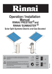
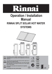
Operation / Installation
Manual
RINNAI ‘PRESTIGE’® and
RINNAI ‘SUNMASTER’®
Solar Split Systems Electric and Gas Boosted
AS 2712
Lic No.1849
SAI Global
All Rinnai gas products
are A.G.A. certified.
WARNING
W169
SAI Global
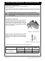
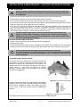
The collector flow and return pipes should be 15mm copper tube or
alternative tube supplied by Rinnai.
Plastic pipe must not be used. Plastic pipe is not suited to the high
water temperatures and pressures that may occur in the collector
flow and return system.
NOT SUITABLE AS A POOL OR SPA HEATER
Distributed and serviced in Australia under a Quality
System certified as complying with ISO 9001 by SAI
Global
15401021
NOTE
The appliance must be installed, commissioned and serviced by an
authorised person in accordance with all applicable local rules and
regulations.
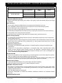
NOTES
TABLE OF CONTENTS
IMPORTANT INFORMATION & WARNINGS...........................................................................................................2
SAFETY & REGULATORY INFORMATION...............................................................................................................................2
SCALDS HAZARDS ..................................................................................................................................................................3
OPERATION PRINCIPLE ..........................................................................................................................................................4
SAFETY DEVICES.....................................................................................................................................................................5
EXCESSIVE DISCHARGE FROM SAFETY DEVICES .............................................................................................................5
WATER TEMPERATURE...........................................................................................................................................................6
TURNING ‘OFF’ THE WATER HEATING SYSTEM ..................................................................................................................6
TURNING ‘ON’ THE WATER HEATING SYSTEM.....................................................................................................................6
WATER QUALITY ......................................................................................................................................................................7
DRAINING AND FILLING THE WATER HEATING SYSTEM ....................................................................................................7
MAINTENANCE AND REGULAR CARE ...................................................................................................................................7
SERVICING AND REPAIR .........................................................................................................................................................7
SAVE A SERVICE CALL ..........................................................................................................................................8
SPECIFICATIONS FOR SYSTEMS ........................................................................................................................10
GENERAL ................................................................................................................................................................................10
SYSTEM SPECIFICATIONS AND DIMENSIONS ...................................................................................................................10
FLOW CONTROL VALVE ........................................................................................................................................................10
DIFFERENTIAL TEMPERATURE CONTROLLER ..................................................................................................................10
SPECIFICATIONS FOR SOLAR COLLECTORS...................................................................................................11
SPECIFICATIONS FOR STORAGE CYLINDERS..................................................................................................12
SPECIFICATIONS FOR GAS BOOSTERS ............................................................................................................15
INSTALLATION & MAINTENANCE - ALL SYSTEMS ...........................................................................................16
REGULATIONS AND OCCUPATIONAL HEALTH AND SAFETY (OH&S) ..............................................................................16
LOCATION - GENERAL INFORMATION .................................................................................................................................16
STORAGE CYLINDER LOCATION .........................................................................................................................................16
GAS BOOSTER LOCATION AND MOUNTING (where applicable) ........................................................................................17
WATER PIPES .........................................................................................................................................................................17
WATER SUPPLY......................................................................................................................................................................17
HOT WATER DELIVERY TEMPERATURE..............................................................................................................................17
VALVES & FITTINGS ...............................................................................................................................................................18
INSTALLATION OF SOLAR COLLECTORS .........................................................................................................18
REGULATIONS AND OCCUPATIONAL HEALTH AND SAFETY (OH&S) ..............................................................................19
SYSTEM ORIENTATION AND INCLINATION .........................................................................................................................19
SOLAR COLLECTOR ROOF MOUNTING OPTIONS .............................................................................................................20
SOLAR COLLECTOR INSTALLATION COMPONENTS .........................................................................................................21
STANDARD INSTALLATION....................................................................................................................................................22
FRAMED INSTALLATIONS - FLAT ROOF FRAMES...............................................................................................................25
FRAMED INSTALLATIONS - CYCLONE FRAME....................................................................................................................26
COMMERCIAL INSTALLATIONS ............................................................................................................................................26
COLLECTOR FITTINGS INSTALLATIONS..............................................................................................................................29
INSTALLATION & MAINTENANCE - GAS BOOSTED SYSTEMS .......................................................................35
OVERVIEW OF SYSTEM COMPONENTS .............................................................................................................................31
GAS BOOSTER LOCATION ....................................................................................................................................................31
GAS SUPPLY...........................................................................................................................................................................31
HOT WATER DELIVERY TEMPERATURE..............................................................................................................................31
CLEARANCES .........................................................................................................................................................................31
GAS BOOSTER MOUNTING...................................................................................................................................................31
INSTALLATION PROCEDURE ................................................................................................................................................43
FILLING THE SYSTEM............................................................................................................................................................44
CHECKING SOLAR PUMP OPERATION................................................................................................................................45
ADJUSTING FLOW CONTROL VALVE ...................................................................................................................................45
PRE SOLAR HEATING CHECKS ............................................................................................................................................45
SOLAR HEATING ....................................................................................................................................................................47
FINISHING THE INSTALLATION .............................................................................................................................................47
DRAINING INSTRUCTIONS....................................................................................................................................................47
INSTALLATION & MAINTENANCE - ELECTRIC BOOSTED SYSTEMS .............................................................48
OVERVIEW OF SYSTEM COMPONENTS .............................................................................................................................48
ELECTRIC SUPPLY.................................................................................................................................................................48
HOT WATER STORAGE AND DELIVERY TEMPERATURES ................................................................................................48
INSTALLATION PROCEDURE ................................................................................................................................................55
FILLING THE SYSTEM............................................................................................................................................................58
CHECK SOLAR PUMP OPERATION ......................................................................................................................................58
ADJUSTING FLOW CONTROL VALVE ...................................................................................................................................58
PRE SOLAR HEATING CHECKS ............................................................................................................................................59
SOLAR HEATING ....................................................................................................................................................................59
FINISHING THE INSTALLATION .............................................................................................................................................59
DRAINING INSTRUCTIONS....................................................................................................................................................60
CONTACT INFORMATION .....................................................................................................................................61
Rinnai Australia
-1-
Solar Split Systems Operating / Installation Manual
IMPORTANT INFORMATION & WARNINGS
SAFETY & REGULATORY INFORMATION
DO NOT operate this system before reading the manufacturers instructions.
WARNING
This appliance must be installed, commissioned and serviced by an authorised person in
accordance with all applicable local rules and regulations.
Access covers of water heating system components will expose 240V wiring and MUST be
removed by an authorised person.
This appliance is not intended for use by persons (including children) with reduced physical,
sensory or mental capabilities, or lack of experience and knowledge, unless they have been given
supervision or instruction concerning use of the appliance by a person responsible for their safety.
For continued safety of this appliance it must be installed, operated and maintained in accordance
with the manufacturers instructions.
Children should be supervised to ensure they DO NOT play with the appliance.
Any power leads from the water heater system components MUST BE plugged into an external
weatherproof electrical outlet. If the power supply cord of any water heating components is
damaged, it MUST BE replaced by an authorised person in order to avoid a hazard, using genuine
replacement parts available from Rinnai. Take care not to touch the power plugs with wet hands.
Care should be taken not to touch the pipe work as it may be HOT! The pipes between the solar
collectors and storage cylinder MUST BE copper, or alternative material pipes that may be
supplied by Rinnai. Plastic pipe is NOT suited to the water temperatures and pressures that may
occur in the system.
DO NOT place articles on or against this appliance.
DO NOT store chemicals or flammable materials near this appliance.
DO NOT operate with collectors or covers removed from this appliance.
DO NOT activate pump unless cylinder is full of water.
NEVER use a flammable spray such as hair spray, lacquer, paint, etc near this unit as this may
cause a fire.
NOTICE TO VICTORIAN CONSUMERS
This appliance must be installed by a person licensed with the Plumbing Industry Commission.
Only a licensed person will have insurance protecting their workmanship.
So make sure you use a licensed person to install this appliance and ask for your Compliance Certificate.
For Further information contact the Plumbing Industry Commission on 1800 015 129.
Rinnai Australia
2
Solar Split Systems Operating / Installation Manual
IMPORTANT INFORMATION & WARNINGS
SCALDS HAZARDS
HOT WATER CAN CAUSE SCALDS.
CHILDREN, DISABLED, ELDERLY AND THE INFIRM ARE AT THE HIGHEST RISK OF
BEING SCALDED.
FEEL WATER TEMPERATURE BEFORE BATHING OR SHOWERING.
SCALDS FROM HOT WATER TAPS CAN RESULT IN SEVERE INJURIES TO YOUNG
CHILDREN.
SCALDS OCCUR WHEN CHILDREN ARE EXPOSED DIRECTLY TO HOT WATER WHEN
THEY ARE PLACED INTO A BATH WHICH IS TOO HOT.
ALWAYS......
Test the temperature of the water with your elbow before placing your child in the bath, also carefully feel
water before bathing or showering yourself.
Supervise children whenever they are in the bathroom.
Make sure that the hot water tap is turned off tightly.
CONSIDER.....
Installing child proof tap covers or child resistant taps (both approaches will prevent a small hand being
able to turn on the tap).
Installing tempering valves or thermostatic mixing valves which reduce the hot water temperature
delivered to the taps. Your local plumbing authority may already require that these be fitted. Contact your
installer or local plumbing authority if in doubt.
NEVER…..
Leave a toddler in the care of another child. They may not understand the need to have the water
temperature set at a safe level.
Rinnai Australia
3
Solar Split Systems Operating / Installation Manual
IMPORTANT INFORMATION & WARNINGS
OPERATION PRINCIPLE
This system is designed to have the solar collectors on the roof and the storage cylinder installed at ground or floor
level.Electric and Gas boosted models are available. The system comprises a hot water storage cylinder, solar
collectors, pump circulation system solar control unit and temperature sensors. The solar control unit ensures
water circulates between the solar collectors and the storage cylinder to transfer heat from the solar collectors to
the water in the cylinder if enough heat is available from the sun.
Supplementary heating is provided if insufficient heat is available from sun (such as during cloudy or rainy weather
or during winter months) either via an electric heating element(s) located inside the storage cylinder or via a on inline Gas booster located external to the storage cylinder. The following diagrams illustrates the Split Solar Hot
Water System set up for both the Electric and Gas boost..
TO HOT WATER
OUTLETS
GAS SUPPLY
PUMP & SOLAR
CONTROL MODULE
PUMP & SOLAR
CONTROL MODULE
TO HOT WATER
OUTLETS
COLD WATER
SUPPLY
COLD WATER
SUPPLY
ELECTRIC ELEMENT
Figure 1. Sunmaster Gas Boosted Hot Water Systems
Figure 2. Sunmaster Electric Hot Water Systems
TO HOT WATER
OUTLETS
PUMP & SOLAR
CONTROL MODULE
COLD WATER
SUPPLY
ELECTRIC ELEMENT
Figure 3. Prestige Electric Hot Water Systems
Rinnai Australia
4
Solar Split Systems Operating / Installation Manual
IMPORTANT INFORMATION & WARNINGS
SAFETY DEVICES
The water heating system is supplied with various safety devices including temperature sensors, overheat sensors
and switches and a Pressure & Temperature Relief (PTR) valve. These devices must not be tampered with or
removed. The water heating system must not be operated unless each of these devices is fitted and is in working
order.
DO NOT tamper with or remove safety devices.
WARNING
DO NOT operate the water heater unless all safety devices are fitted and in working order.
DO NOT block or seal the PTR Valve and drain pipe.
Pressure & Temperature Relief (PTR) Valve
This valve is located near the top of the water heater
and is essential for safe operation. It is normal for the
valve to release a small quantity of water through the
drain line during heating.
However, continuous leakage of water from the
valve and its drain line may indicate a problem with
the water heater.
WARNING
Twist cap until water
flows from drain line
Lift lever until water
flows from drain line
(Lower lever genlty!)
Never block the outlet of the PTR valve or it’s drain line for any reason. The easing gear must be
operated at least every 6 months to remove lime deposits and verify that it is not blocked. Failure
to do this may result in the water heater failing.
If the valve does not discharge water when the easing gear lever is opened, or does not seal again
when the easing gear is closed, attendance by an authorised person must be arranged without
delay. The PTR valve is not serviceable.
EXCESSIVE DISCHARGE FROM SAFETY DEVICES
Pressure & Temperature Relief (PTR) Valve
It is normal and desirable that this valve allows a small quantity of water to be discharged during the heating cycle.
If it discharges more than a bucket of water during a 24 hour period or discharges continuously there may be
another problem.
If the valve dribbles continuously, try easing the valve gear for a few seconds as described above. This may
dislodge any foreign matter and alleviate the problem.
If the valve discharges at high flows, especially at night, it may be as a result of the water pressure exceeding the
design pressure of the water heater. Ask your installer to fit a Pressure Limiting Valve (PLV).
NEVER replace the PTR valve with one which has a higher pressure rating than is specified for your
water heater.
WARNING
Expansion Control Valve (ECV) - if fitted
It is normal and desirable that this valve allows a small quantity of water to be discharged during the heating cycle.
If it discharges more than a bucket of water during a 24 hour period or discharges continuously there may be
another problem.
If the valve leaks continuously, try easing the valve gear for a few seconds. This may dislodge any foreign matter
and alleviate the problem. If this does not alleviate the problem contact Rinnai.
Operate the easing gear regularly to remove any lime deposits and to verify that it is not blocked.
Rinnai Australia
5
Solar Split Systems Operating / Installation Manual
IMPORTANT INFORMATION & WARNINGS
Gas boosted models
•
Do not touch the flue outlet or do not insert any objects into the flue outlet.
•
Keep flammable materials, spray cans, fuel containers, trees, shrubs and pool
chemicals etc. well clear of the flue outlet.
•
Do not use the gas types other than those designated on the data plate. For
example, do not use Propane/Butane gas mixtures on appliances marked Propane
Gas.
•
Do not use Propane gas on appliances marked as Natural gas and vice versa.
H OT !
Hydrogen Gas
In the case of systems using a vitreous enamelled lined cylinder, if the hot water unit is not used for two weeks or
more, a quantity of hydrogen gas, which is highly flammable, may accumulate in the water heater. To dissipate this
safety, it is recommended that a non electrically operated hot tap be turned on for two minutes at a sink, basin, or
bath, but not a dishwasher or other appliance. during this procedure there must be no smoking, open flame or any
electrical appliance operating nearby. If hydrogen is discharged through the tap, it will probably make a sound like
air escaping.
WATER TEMPERATURE
The solar control unit and pump ensure water circulates between the solar collectors and storage cylinder until the
water at the base of the cylinder reaches approximately 65°C. Under these conditions water at the hot outlet may
exceed 85°C. During periods of low solar gain supplementary heating occurs to a minimum of 60°C as required.
To meet Australian regulatory requirements, supplementary heating temperature settings
must be at least 60°C.
IMPORTANT
TURNING ‘OFF’ THE WATER HEATING SYSTEM
If you plan to be away for only a few nights, we suggest you leave the water heating system switched on. If it is
necessary to switch off the water heater, do so as outlined below:
Electric Boosted systems
• Switch off the electric supply to the supplementary heating element. The switch is usually marked and
located in the electricity meter box of the dwelling.
• Switch off the electric supply to the solar controller and pump.
Gas Boosted systems
• Switch off the electric supply to the gas booster.
• Switch off the electric supply to the solar controller and pump.
TURNING ‘ON’ THE WATER HEATING SYSTEM
Electric Boosted system
• Switch on the electric supply to the supplementary heating element(s). The switch is usually marked and
located in the electricity meter box of the dwelling.
• Switch on the electric supply to the solar controller pump. Electric and solar water heating will now occur as
required. It may take a number of hours before hot water is available.
Gas Boosted systems
• Switch on the electric supply to the gas booster.
• Switch on the electric supply to the solar controller and pump. Solar water heating will now occur. Hot
water is available immediately from the gas booster when hot water tap is opened, irrespective of solar
heat gain.
Rinnai Australia
6
Solar Split Systems Operating / Installation Manual
IMPORTANT INFORMATION & WARNINGS
WATER QUALITY
The water quality of most public supplies is suitable for the water heating system. The water quality from bore wells
is generally unsuitable for the water heating system. Refer to separate 'Warranty Terms and Conditions' document
for water quality parameters and how they affect the warranty conditions. If in doubt about the water quality, have
it checked against the parameters listed in the warranty conditions. The system is not suitable as a pool or spa
heater.
DRAINING AND FILLING THE WATER HEATING SYSTEM
• Draining or filling normally occur only during installation or servicing and must be carried out by an
authorised person.
MAINTENANCE AND REGULAR CARE
Operate the easing gear of the PTR as described under “” on page 4.
The overflow tray (supplied by installer) and drain underneath the storage cylinder (if fitted) should be periodically
checked to ensure there are no blockages.
SERVICING AND REPAIR
Our Servicing network personnel are fully trained and equipped to give the best service on your appliance. If your
appliance needs service, ring one of the service contact numbers on the back of this booklet.
It is recommended that the system be serviced at least every 5 years.
The pressure and temperature relief valve and expansion control valve must be checked for performance or
replaced by an authorised person at intervals not exceeding 5 years or more frequently in areas where the water
is classified as scaling water (refer to ‘Warranty Terms and Conditions’ document - ‘Water Quality’).
It is recommended that the sacrificial anode fitted to Sunmaster cylinders be inspected very 5 years or more
frequently in areas where there is a high incidence of water deposits. This does not apply to Rinnai Prestige
cylinders. Anodes suited to hard and soft water, are available from Rinnai.
If the electric conduit, power supply cord or plug to the water heater is damaged, they must be replaced by an
authorised person in order to avoid a hazard. The power supply cord and plug (if fitted) must be replaced by a
genuine replacement part available from Rinnai.
Rinnai Australia
7
Solar Split Systems Operating / Installation Manual
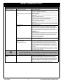
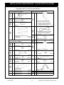
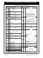
SAVE A SERVICE CALL
Table 1 - Troubleshooting
Problem
Insufficient or no hot Water
Cause
Remedy
Booster heating not operating
Or
Insufficient gas supply for gas boosted heating
system
Excessive hot water consumption
Electric Boosted Systems:
If the water goes cold, are you using more hot water than you think? Often end
users are surprised at the amount of hot water used, especially when showering. If
the amount of hot water used during the day exceeds the storage capacity of the
cylinder, it is likely that there will be insufficient hot water. Has your plumber install
water saving fixtures and/or flow control or pressure limiting valves to reduce
consumption.
Gas Boosted Systems:
Insufficient flow may occur if multiple outlets are in use at the same time and exceed
the rated flow capacity of the gas booster. If so, reduce the number of outlets in use.
Have your plumber install water saving fixtures and/or flow control or pressure
limiting valves to reduce consumption.
Check correct size gas booster is fitted.
Incorrect Solar system size
Do you have the correct system size and configuration for your requirements? Refer
to Rinnai literature for information.
Temperature and pressure relief valve /
Expansion Control valve
discharging water continuously
Pressure and Temperature Relief (PTR) valve
It is normal and desirable that this valve allows a small quantity of water to be
discharged during the heating cycle. If it discharges more than a bucket of water
during a 24 hour period or discharges continuously there may be another problem.
If the valve dribbles continuously, try easing the valve gear for a few seconds as
described under 'Regular Care'. This may dislodge any foreign matter and alleviate
the problem.
If the valve discharges at high flows, especially at night, it may be as a result of the
water pressure exceeding the design pressure of the water heater. Ask your installer
to fit a Pressure Limiting Valve (PLV).
•
•
WARNING
Never replace the PTR valve with one which has a higher pressure rating than is specified for your water heater.
If the valve discharges hot water at high flows, (dumps) there may be a serious problem. Switch off the power
supply in the meter box (the switch marked ‘WATER HEATER’ or ‘HOT WATER’) or the isolating switch installed
near the water heater and contact Rinnai.
Insufficient or no hot Water
Continued
Rinnai Australia
Electric boosted Systems: Check to ensure the electric isolating switch(es) at the switchboard (usually marked
"Hot water" or "water heater") is switched 'ON'.
Check to ensure that the electric fuses for hot water at the switchboard are intact.
Gas Boosted Systems: Check to ensure the power cord of the gas booster is plugged in and the power point
switched 'ON'.
Check gas is available and turned ON'.
Close the hot tap and wait for 10 seconds and open it again. The hot tap must be
opened enough to ensure that the flow rate is not less than 2.4 L/min. gas the gas booster burners will not light if it is less than 2.4 L/min. Check the
isolation valve in the gas line is opened.
If there is gas supply to other appliances in the rest of the house, try lighting another
gas appliance.
Refer to your plumber to ensure the gas line has been purged of air after installation.
Expansion Control Valve (ECV) - if fitted
It is normal and desirable that this valve allows a small quantity of water to be
discharged during the heating cycle. If it discharges more than a bucket of water
during a 24 hour period or discharges continuously there may be another problem. If the valve leaks continuously, try easing the valve gear for a few seconds as
described under 'Regular Care'. This may dislodge any foreign matter and alleviate
the problem. If this does not alleviate the problem contact Rinnai.
8
Solar Split Systems Operating / Installation Manual
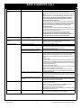
SAVE A SERVICE CALL
Problem
Cause
Remedy
Insufficient or no hot Water
continued
Booster element Thermostat Settings
Electric Boosted Systems:
The end user can check the temperature of hot water delivered with a
thermometer placed under the closest non tempered outlet (usually the kitchen
sink).
CAUTION: Take care to avoid scalding. This test should be done early in
the morning after overnight electrical boosting before any hot water is
used. The temperature of the water delivered should be at least 55° C
(allowing for heat losses in pipe work). If this is not the case or the temperature needs to be increased contact Rinnai.
The thermostat settings of the heating element thermostat can also be confirmed
directly by a qualified person as described under 'hot water storage & delivery
temperature'. The settings can be increased if required. Contact Rinnai.
Gas Boosted Systems:
The delivery temperature of gas boosted systems is normally 60 or 65°C. Iff
temperatures are higher than this, the flow of water through the gas booster will
reduce and may result in insufficient flow rate.
The end user can check the temperature of hot water delivered with a
thermometer placed under the closest outlet (usually the kitchen sink).
CAUTION: Take care to avoid scalding. If the temperature is higher than
65°C the gas booster may be preset incorrectly. Contact Rinnai.
No Water from the hot tap
Restriction in the hot tap or failure of the cold water
supply to the water heater.
Check for water flow at the other taps and that the cold water isolation is fully
open.
Gas Booster operating too
frequently
Insufficient Sunlight - Collectors shaded
Ensure the trees or other objects are not shading onto the collector surface (Trim
the trees or relocate the solar collector if the obstruction is permanent).
Make sure the glass on the collector is not dirty.
High electricity or gas bill
Excessive hot water consumption
See entry under 'Insufficient hot water'.
Solar Control unit switched off
If the solar control unit is switched off there will be no solar pre-heating of water
resulting in the water being heated entirely by electricity or gas' boosting'. Check
the power outlet for the solar control unit is switched on.
Temperature and pressure relief valve / Expansion
Control valve discharging water continuously
See entry under 'Insufficient hot water'.
Lack of solar gain
Reduced sunlight:
Reduced sunlight due to overcast weather in summer or low solar contribution in
winter will result in an increased dependence on electricity or gas boosting.
Higher electricity or gas bills under these conditions, especially in winter, are
normal.
Collectors shaded:
If the solar collectors are shaded by trees or other objects, or the glass is dirty,
the effectiveness of the collectors is greatly reduced. Arrange for trimming of the
trees or relocation of the solar collectors if the obstruction is permanent. Arrange
for cleaning of the collector glass.
Solar collectors incorrectly positioned
Check that positioning and alignment of solar collectors is in accordance with the
section 'Location and alignment of solar collectors'.
WARNING: Persons working from elevated surfaces such as roofs must be
adequately trained an qualified in accordance with local OH&S requirements.
High Electricity Tariffs (electric boosted systems only) Electric Boosted Systems
The electricity tariff will determine the running costs of the system. It is important
the end user is aware of the applicable tariffs. Contact your electricity supplier to
confirm what these tariffs are.
Little or no water circulation in the solar 'flow and
return' loop
There are numerous causes of little or no circulation in the solar 'flow and return
circuit the circulation of water through the collectors. These causes must be
investigated by a qualified person. Contact Rinnai.
Water flow fluctuations
One or more hot taps opened at the same time
More than one or two hot taps in use at the same time may cause a decrease in
the hot water flow from the taps.
Is there more than one or two hot taps open, or are appliances such as a
dishwasher or washing machine, in use at the same time?
Ensure only one or two hot taps are on at one time.
Check the flow of the water from one tap, eg. the shower. The shower should be
adjusted so the hot tap is fully open.
Water Hammer
Hot and cold water plumbing in the premises
Have a plumber check clipping of hot and cold water pipework and install a
pressure limiting valve and water hammer arrestor as required.
Rinnai Australia
9
Solar Split Systems Operating / Installation Manual
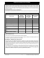
SPECIFICATIONS FOR SYSTEMS
GENERAL
Split solar hot water systems are specified according to the grade of storage cylinder material, cylinder
capacity, number of solar collectors and boost type and capacity. Boost capacity for gas boosted
system depends on the gas booster model selected. Boost capacity for electrically boosted systems
depends on the power rating of electric heating elements and whether one or two electric heating
elements are fitted.
SYSTEM SPECIFICATIONS AND DIMENSIONS
Specifications and principal dimensions for the various systems and components are shown below.
Table 2 - System Specifications
System Type
Rinnai ‘Sunmaster’ Rinnai ‘Sunmaster’
Rinnai ‘Prestige’
Systems
Systems
Systems
SG270, SG340,
SG175, SG215,
SE315
SE160, SE200
Connections:
Solar flow and return
1/2”
1/2”
1/2”
PTR Valve
1/2”
1/2”
3/4”
Cold Inlet
3/4”
3/4”
3/4”
Hot Outlet
3/4”
3/4”
3/4”
PTR Valve setting (kPa)
1000
850
850
Rating of PTR Valve supplied (kW)
10
10
10
Expansion Control Valve (ECV) setting
(kPa)
850
700
700
Max supply pressure with ECV (kPa)
680
550
560
Max supply pressure without ECV
(kPa)
800
680
700
Pressure limiting valve rating (kPa)
(supplied by installer if required)
500
500
500
FLOW CONTROL VALVE
A flow control valve is fitted to the pump and controller assembly.
It’s purpose is to allow the water flow rate through the collector collectors and storage cylinder to be
controlled to optimise the performance of the system.
DIFFERENTIAL TEMPERATURE CONTROLLER
The primary task of the differential temperature controller is to control the operation of the pump to
optimize solar energy collection. This task is performed by measuring the temperature differential
between the hot sensor and the cold sensor. When the differential exceeds 9°C the pump is activated
and water passes through the collectors collecting solar energy. When the differential falls below 5°C
the pump is shut down.
A secondary task of the controller is to stop energy collection when the cylinder is full of hot water.
This is referred to as no load protection and the pump is shut down if the temperature of the water
going to the collectors exceeds 65°C. At such a temperature in the base of the cylinder, the
temperature of water in the top of the cylinder is expected to be about 85°C.
Rinnai Australia
- 10 -
Solar Split Systems Operating / Installation Manual
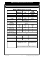
SPECIFICATIONS FOR SOLAR COLLECTORS
Table 3 - Model Numbers and Specifications
MODEL NUMBERS AND SPECIFICATIONS
CHARACTERISTICS
Enduro / Equinox
(SP200A) or
(SP200A FTC)
Excelsior
(EXT OR EXT
FTC)
E-FROST
(HPFTC- 8-10)
TYPE
Flat plate
Flat plate
Flat Plate /
Heat Pipe
- Waterways
Copper
Copper
Copper
- Absorber
Aluminium
Copper
Aluminium
- Selective Surface
High Performance
Sputtered
Titanium Oxide
High Performance
CONSTRUCTION
Maximum Operating
Pressure
850 kPa
Casing Material
Aluminium
Overall Dimensions
(L x W x H) (mm)
1940 x
1025 x
80
1964 x
1047 x
81
1940 x
1025 x
80
Weight empty
(STD/FTC) (kg).
33 / 35
35 / 38
34
Water volume (Litres)
1.3
1.5
0.6
Number risers
8
10
10
Potential Solar Output at
PTR relief conditions (kW)
1.25
Approximate Roof space Required: Length x Width
- 1 Collector (mm)
1940 x 1025
1940 x 1047
1940 x 1025
- 2 Collectors (mm)
1940 x 2130
1940 x 2174
1940 x 2130
- 3 Collectors (mm)
1940 x 3235
1940 x 3301
1940 x 3235
Commercial Systems
Frost Protection
Refer to Figure 23 for details
* Standard version - no frost
protection
Frost Protection to -5°C
*Frost protection to -12°C.
Power must be on at the
pump and controller must
be in low temperature mode
(factory default).
* FOR MORE INFORMATION ON FROST PROTECTION REFER TO
WARRANTY BOOKLET
Rinnai Australia
- 11 -
Solar Split Systems Operating / Installation Manual
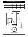
SPECIFICATIONS FOR STORAGE CYLINDERS
SUNMASTER - ELECTRIC - VITREOUS ENAMEL
SE160
SE200
SE315
PTR / Solar Return / Hot Water Outlet
1310
1605
1200
Flow line to Collectors
665
665
700
Cold Water Inlet
225
225
260
Cylinder Height
1530
1825
1510
Diameter
515
515
685
Weight Empty (kg)
71
83
100
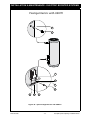
CYLINDER HEIGHT
HOT WATER OUTLET
P&TR VALVE
COLD
WATER
INLET
FLOW LINE TO COLLECTORS
PTR / SOLAR RETURN
SOLAR
RETURN
CYLINDER DIAMETER
TEMPERATURE
SENSOR
DRY WELL
Figure 4 - Dimensional Drawing - Rinnai Sunmaster Vitreous Enamel Storage Cylinder
- Electric Boosted Split Systems
Rinnai Australia
- 12 -
Solar Split Systems Operating / Installation Manual
SPECIFICATIONS FOR STORAGE CYLINDERS
SUNMASTER GAS - VITREOUS ENAMEL
SG175
SG215
SG270
SG340
Cylinder Height
1530
1825
1265
1510
PTR / Solar Return
1310
1605
985
1200
Flow line to collectors
665
665
700
700
Cold Water Inlet
225
225
260
260
Gas Supply and Hot Water Outlet
940
1235
675
920
Gas Booster Flue Outlet
1400
1695
1135
1380
Diameter
515
515
685
685
Weight Empty (kg)
66
88
95
103
GAS BOOSTER FLUE OUTLET
GAS SUPPLY AND
HOT WATER OUTLET
P&TR VALVE
COLD
WATER
INLET
FLOW LINE TO COLLECTORS
P&TR / SOLAR RETURN
CYLINDER HEIGHT
SOLAR
RETURN
CYLINDER DIAMETER
SYSTEM DEPTH
TEMPERATURE SENSOR
DRY WELL
Figure 5 - Dimensional Drawing - Rinnai Sunmaster Vitreous Enamel Storage Cylinder Gas Boosted Split Systems
Rinnai Australia
- 13 -
Solar Split Systems Operating / Installation Manual
SPECIFICATIONS FOR STORAGE CYLINDERS
PRESTIGE ELECTRIC - STAINLESS STEEL
PRESTIGE ELECTRIC
160
250
315
1490
1880
Cylinder Height
1205
1700
2090
Weight Empty (kg)
44
56
68
SOLAR
RETURN
CYLINDER HEIGHT
995
P&TR VALVE & HOT WATER OUTLET
PTR / Solar Return / Hot Water Outlet
650
300
210
600
COLD
WATER
INLET
Figure 6 - Dimensional Drawing - Rinnai Prestige Stainless Steel Storage Cylinder
- Electric Boosted Split systems
Rinnai Australia
- 14 -
Solar Split Systems Operating / Installation Manual
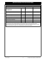
SPECIFICATIONS FOR GAS BOOSTERS
Table 4 - Specifications - Gas Boosters
Model Name:
S20
S26
Boost Capacity:
- L/min. @ 20°C rise
- L/min @ 25°C rise
(L/min)
20
16
26
24
Maximum Rated Flow:
(L/min)
20
26
Minimum Supply Pressure for Maximum rated flow:
(kPa)
120
200
(L/min)
2.4
2.4
Yes
Yes
125 - 18
188 - 23
Star Rating (AS 4552 - 1998):
5.5
5.0
Hot Water Delivery Temperature: (2)
60°C
60°C
(1)
Minimum Flow for Operation:
Frost Protection:
Gas Consumption (Maximum / Minimum):
(MJ/hr.)
Dimensions: Height x Width x Depth:
(mm)
530 x 350 x 194
530 x 350 x 194
Weight:
(Kg)
15
21
(1) - Units will operate at lower pressures but the rated flow with not be achieved.
(2) - Gas boosters for Solar hot water applications should be preset to deliver a minimum temperature of 60°C.
Gas boosters factory pre set to 60°C or 65°C will be marked as such. If there are no temperature markings on the water
heater, on site conversion is required. This is a simple procedure, contact your Service Agent.
Rinnai Australia
- 15 -
Solar Split Systems Operating / Installation Manual
INSTALLATION & MAINTENANCE - ALL SYSTEMS
REGULATIONS AND OCCUPATIONAL HEALTH AND SAFETY (OH&S)
WARNING
Installation and commissioning must be performed by authorised persons. Solar systems must be installed in accordance with these instructions and all
regulatory requirements which exist in your area including those in relation to
manual lifting, working at heights and on roofs. Applicable publications and
regulations may include:
• AS 5601 Gas Installations
• AS/NZS 3500 National Plumbing and Drainage
• AS/NZS 3000 Wiring rules
• Building Codes of Australia (BCA)
• Local Occupational Health and Safety (OH&S) regulations
This appliance is not suitable for use as a domestic spa pool or swimming pool
heater.
Solar collectors are heavy and bulky items and are usually positioned on the
roofs of buildings. Australian State and Territories have a principal Occupational
Health and Safety (OH&S) Act which contains requirements relating to the
handling of large, bulky or awkward items and the prevention of falls from
elevated surfaces. Persons installing solar collectors must be aware of their
responsibilities and be adequately trained and qualified, in accordance with
local OH&S requirements.
LOCATION - GENERAL INFORMATION
All system components must be in an accessible location. The storage cylinder must be accessible
without the use of a ladder or scaffold. Sufficient clearances shall allow access to, and removal of,
all serviceable parts. Ensure the PTR valve, pump kit, drain lines and thermostat and elements for
electric systems have sufficient clearances and are accessible for service and removal. The
information on any data plates must also be readable. In the case of vitreous enamel lined cylinders,
leave a clearance of the height of one storage cylinder above the cylinder being installed so the
sacrificial anode can be inspected and replaced. This does not apply to stainless steel cylinders.
Select suitable areas of roof on which to install the solar collectors as close as practicable to the
cylinder. Ensure that the area is even and without cracked or damaged tiles. Collectors should be
positioned for optimum solar benefit. Refer to the section 'INSTALLATION OF SOLAR
COLLECTORS' for more information.
The solar pump kit and gas booster heater require an AC 240V power supply. A weatherproof 240V,
10A earthed power point must therefore be provided adjacent to these. All electrically boosted solar
hot water heating elements must be connected to an independent, fused, AC 240V 50 Hz power
supply with an isolating switch installed at the switch board.
STORAGE CYLINDER LOCATION
The storage cylinder should be placed as close as practicable to the most frequently used hot water
outlet point or points to minimise the delay time for hot water delivery. This will usually be the kitchen
tap.
The solar storage cylinders have an ingress protection rating of IPX4 making them suitable for
internal or external installation. Rinnai 'external' gas boosters are suitable for external installation
only.
Storage cylinders must be installed in freestanding mode on a level and stable base. For external
installations, storage cylinders should be mounted on a concrete base at least 50mm thick or on well
seasoned, evenly spread hardwood slats with a thickness of at least 25mm. Where property damage
can occur, storage cylinders should be installed with an approved safe tray (overflow tray).
Ensure the cylinder does not stand on wet surfaces.
Rinnai Australia
- 16 -
Solar Split Systems Operating / Installation Manual
INSTALLATION & MAINTENANCE - ALL SYSTEMS
GAS BOOSTER LOCATION AND MOUNTING (where applicable)
The gas booster is designed for 'Outdoor' Installation only. As such, it must be located in an above
ground open air situation with natural ventilation, without stagnant areas, where gas leakage and
products of combustion are rapidly dispersed by wind and natural convection. WATER PIPES
All hot water pipework should be insulated with sealed Polyethylene foamed or equivalent insulation
to optimise performance and energy efficiency. Such insulation may also be mandatory under local
regulations. With the exception of solar collector flow and return pipes, water pipe sizing should be
performed in accordance with AS/NZS 3500.
WARNING
The collector flow and return pipes should be a minimum of 15 mm copper tube.
Plastic pipe must not be used. Plastic pipe is not suited to the high water
temperatures and pressures that may occur in the collector flow and return
system.
The maximum recommended combined lengths of the solar cold and solar hot pipes are as follows:
Table 5 - Collector Flow and return pipe sizing
Number of Collectors
1-2
3
40
30
Not recommended
40
Pipe Size
DN 15 (metres)
DN 20 (metres)
4
15
20
WATER SUPPLY
The minimum and maximum water pressures for the various systems are listed in Table 2. Approved
pressure limiting valves may be required if the 'Maximum' rated water supply pressures are
exceeded. For gas boosted systems to achieve the rated flow through the outlet of the continuous
flow water heater, the minimum water supply pressures must be supplied. The systems will operate
at lower pressures but the rated flow will not be achieved.
Water chemistry and impurity limits are detailed in the separate Warranty document. Most
metropolitan water supplies fall within these requirements. If you are unsure about water quality,
contact your water authority. If sludge or foreign matter is present in the water supply, a suitable filter
should be incorporated in the water supply to the storage cylinder.
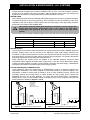
HOT WATER DELIVERY TEMPERATURE
Local regulations and/or the requirements of AS/NZS3500.4 must be considered regarding the
temperature limitations of hot water supplied to areas used primarily for personal hygiene. The
temperature of water to these areas is limited to 45°C for early childhood centres, primary and
secondary schools and nursing homes or similar facilities for young, aged, sick or people with
disabilities and 50°C for all other buildings. To comply with these requirements, a temperature
limiting device, such as a thermostatic mixing or tempering valve, will be required on all solar hot
water systems as detailed in Figures 7 and 8.
Rinnai gas continuous
flow water heater for
solar applications,
preset to deliver
hot water at a fixed
temperature of 60°C or higher
Cold Inlet
Gas supply
Kitchen
Laundry
Ensuite
Bathroom
TLD
Note: TLD = Temperature Limiting Device
Cold water supply
Figure 7 - Tempered gas hot water systems
Rinnai Australia
r co
to
llec
Electrically
boosted
storage
cylinder
rs
Solar hot water return
Gas boost
Hot water outlet
Cold water supply
Solar hot water return
Solar cold water inlet
Storage
cylinder
Solar cold water inlet
Sola
Heated water from storage cylinder
rs
ecto
coll
Heated water from storage cylinder
r
Sola
Kitchen
Laundry
Ensuite
Bathroom
TLD
Note: TLD = Temperature Limiting Device
Figure 8 - Tempered Electric hot water systems
- 17 -
Solar Split Systems Operating / Installation Manual
INSTALLATION & MAINTENANCE - ALL SYSTEMS
VALVES & FITTINGS
The following valves and fittings are supplied with your solar hot water system:
• A combined pressure and temperature (PTR) relief valve, capacity 10 kW. Relief valve pressure settings vary with models. This valve is fitted at the top of the storage
cylinder. The PTR valve is a safety device and it is mandatory that it is fitted by the installer in all
installations.
• A non return valve fitted on the solar pump outlet to prevent backflow through the pump from
the solar collectors. This valve is factory connected.
• For gas boosted systems, elbow connections for the hot, cold and gas supply are fitted at the
bottom of the gas booster.
• Fittings as shown in Figures 27 - 30 and 34 - 36.
The following valves & fittings are to be supplied by the installer:
• A cold water expansion control valve (ECV). An ECV must be fitted in Western Australia and
South Australia to the cold water supply to the storage cylinder to comply with local regulations.
An ECV is recommended in all other geographical areas where the water supply has a
tendency to cause scaling. This will reduce hot water discharge from the Pressure and
Temperature Relief (PTR) valve which minimises wear on this valve.
• A stop cock, non return valve and line strainer. Combination valves incorporating two or more
of these functions (such as 'Trio' valves) are suitable. These are fitted to the cold water supply
to the storage cylinder by the installer.
•
•
•
•
Cold water supply and hot water discharge pipework to and from the storage cylinder.
Solar collector flow and return pipes and storage cylinder connections.
An isolating valve and connection union for the gas supply to the gas booster.
A approved pressure limiting valve (supplied with some systems) is required if the maximum
rated water supply pressure in Table 2 is exceeded.
Rinnai Australia
- 18 -
Solar Split Systems Operating / Installation Manual
INSTALLATION OF SOLAR COLLECTORS
REGULATIONS AND OCCUPATIONAL HEALTH AND SAFETY (OH&S)
Installation and commissioning must be performed by authorised persons. Rinnai solar systems must be
installed in accordance with these Instructions and all regulatory requirements which exist in your area
including those in relation to manual lifting, working at heights and on roofs. Applicable publications and
regulations may include:
•
•
•
•
•
AS 5601 Gas Installations
AS/NZS 3500 National Plumbing and Drainage
AS/NZS 3000 Wiring rules
Building Codes of Australia
Local Occupational Health and Safety (OH&S) regulations
•
WARNING
Solar collectors are heavy and bulky items and are usually positioned on the
roofs of buildings. Each Australian State and Territory has a principal
Occupational Health and Safety (OH&S) Act which contains requirements
relating to the handling of large, bulky or awkward items and the prevention of
falls from elevated surfaces. Persons installing solar collectors must be aware
of their responsibilities and be adequately trained and qualified, in accordance
with local OH&S requirements.
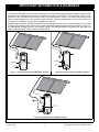
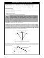
SYSTEM ORIENTATION AND INCLINATION
The performance of any solar hot water system is determined by the way that the system is installed.
In Australia, the solar collectors should face the equator (North) as shown below. Where this orientation
is not practical, collectors facing within 45 degrees from North (between North-East and North-West)
area acceptable, with a reduction in efficiency of approximately 5%. If the bulk of hot water consumption
occurs before 2 pm face the collectors in a North - Easterly direction. If the bulk of hot water consumption
occurs after 2 pm face the collectors in a North Westerly direction.
(Ideal gives 3 hours either side of noon day sun)
North
45o
45o
West
East
South
Figure 9 - Orientation angle of Collectors
The inclination of the solar collectors should ideally be the same as the latitude angle of the site.
Inclinations within 20 degrees of the latitude angle of the site are acceptable, with a reduction in efficiency
of approximately 5%.
North
City Latitude +/- 20o
Figure 10 - Inclination of Collector
Rinnai Australia
- 19 -
Solar Split Systems Operating / Installation Manual
INSTALLATION OF SOLAR COLLECTORS
Table 6: Latitudes of Australian Cities
City
Adelaide
Alice Springs
Brisbane
Broken Hill
Latitude
35°S
24°S
27°S
31°S
City
Cairns
Canberra
Darwin
Geraldton
Latitude
17°S
35°S
12°S
28°S
City
Hobart
Mildura
Melbourne
Perth
Latitude
42°S
34°S
38°S
32°S
City
Port Hedland
Rockhampton
Sydney
Townsville
Latitude
20°S
24°S
34°S
19°S
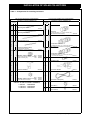
For all installations the collector bank must slope upwards approximately 8 mm per collector from inlet to
outlet as shown below:
HOT CONNECTION
BLANKED OFF
CONNECTION
COLD
BLANKED OFF
CONNECTION
CONNECTION
BLANKED OFF
CONNECTION
COLD
CONNECTION
HOT CONNECTION
BLANKED OFF
CONNECTION
COLD
CONNECTION
COLLECTOR BANK MUST SLOPE
UPWARDS APPROX 8 mm PER COLLECTOR
COLLECTOR BANK MUST SLOPE
UPWARDS APPROX 8 mm PER COLLECTOR
Figure 11 - Enduro, Equinox, Excelsior
Collectors
Figure 12 - E-Frost Collectors
A maximum of three collectors can be connected together in parallel. Inlet (Cold) and outlet (Hot)
connections are made at opposite corners of the collector array.
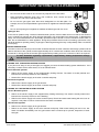
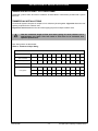
SOLAR COLLECTOR ROOF MOUNTING OPTIONS
For mounting options not shown in Figure 13, for example in areas where the cyclone frame cannot not
be used, consult your nearest Rinnai Branch or Rinnai Representative.
It is normal to mount the solar collectors down close to the gutter. Roof construction must be checked to
ensure that the roof timbers are capable of supporting the additional load. (Refer to AS3500.4 Appendix
H).
For tiled roof installations. Check for cracked or damaged tiles in the area of proposed installation.
Replace any faulty tiles. If spare tiles are not available, swap damaged tiles with good ones from along the gutter line.
REVERSE PITCH FRAME
FLAT ROOF FRAME
STANDARD
N
N
CYCLONE FRAME
SIDE PITCH FRAME
N
N
N
Figure 13 - Solar Collector Roof Mounting Options
Rinnai Australia
- 20 -
Solar Split Systems Operating / Installation Manual
INSTALLATION OF SOLAR COLLECTORS
SOLAR COLLECTOR INSTALLATION COMPONENTS
Table 7 - Components for installing Collectors
COLLECTOR MOUNTING COMPONENTS
(supplied in Collector Installation kit)
1
Number of
Collectors
2
3
2
-
-
1
2
-
Number of
Collectors
2
3
Mounting Rail Small
14201196
-
COLLECTOR CONNECTING COMPONENTS
(supplied in Collector Installation kit)
2
2
2
Stop End
(1 x plug ¾G (Kinco) + 1 x ¾ Kinco nut and olive)
(Not used with E-Frost Collector)
Mounting Rail Medium
14201197
-
-
2
Mounting Rail Large
2*
+
#
2
28801025
14201198
-
2
4
Compression Union ¾ - ¾
4*
(1 x Nipple G¾ (Kinco) + 2 x ¾ Kinco nut and olive)
32201709
(Half of these not used with E-Frost Collector)
6*
Collector Mounting Strap
* supplied with collectors,
# supplied in collector installation kit
12401012
1
1
1
Compression Union ¾ - ½
4
4
4
8
4
M8 Bolt, Washer and Nut
BOLT
(used to bolt collector mounting WASHER
strap to mounting rail)
NUT
1
2
8
(1 x Nipple G¾ (Kinco) + 1 x ¾ Kinco nut and olive
+ 1x ½ Kinco nut and olive )
33201711
1
1
1
Collector Retainer
4
22601052
17401072
16801062
1
1
(used with collector retainers)
BOLT
WASHER
NUT
1
1
1
- 21 -
1
11007701
Hot Sensor Sheath
10204714
Hot Sensor Lead (20 m)
31002706
Kinco Nut ½
16801012
Kinco Olive ½
33001012
1
22601073
17401073
16801007
INSTALLATION KITS PART NUMBERS
1 collector : R33202739
2 collectors : R33202740
3 collectors : R33202741
Rinnai Australia
1
Air Bleed Valve
1
26601706
12
M6 Bolt, Washer and Nut
1
1
1
Solar Split Systems Operating / Installation Manual
INSTALLATION OF SOLAR COLLECTORS
STANDARD INSTALLATION
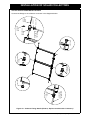
Collector Mounting Component Pre Assembly for a Standard Installation
• Assemble the collector rail components as shown in Figure 14 below.
• Only loosely attach the collector retainers to the rails.
COLLECTOR SUPPORT STRAPS
MOUNTING RAIL
COLLECTOR RETAINERS
M6 BOLT, NUT &WASHER
COLLECTOR SUPPORT STRAPS
MOUNTING RAIL
COLLECTOR RETAINERS
M6 BOLT, NUT &WASHER
Figure 14 - Collector Mounting Components
This installation is not suitable for use in cyclonic areas. For further details, please
contact your local Rinnai Solar distributor.
NOTE
Rinnai Australia
- 22 -
Solar Split Systems Operating / Installation Manual
INSTALLATION OF SOLAR COLLECTORS
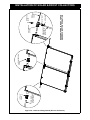
STANDARD INSTALLATION CONTINUED
Fastening (Collectors to a Metal Roof)
This installation is not suitable for in cyclonic areas. For further details, please
contact your local Rinnai Solar distributor.
NOTE
• Position the lower collector mounting rail
Tiles removed
assembly so that the rail is angled to ensure
the collectors have an 8 mm / collector rise.
• For aesthetic reasons it is best to mount as
close as possible to the gutter.
Nail strap to rafter
• Attach the collector mounting straps to the
rafter or truss under the tiles as shown in
Figure 15.
Figure 15 - Mount Lower Collector Rail
• Place the collector(s) onto the roof above the
lower rail. If more than one collector is being
installed then join them together using the
compression fittings supplied.
• Push down on the collector retainers to clamp
the collector and tighten the nuts as shown in Figure 16.
Figure 16 - Mount collector on Roof
• Position the upper collector rail above the
collectors. Push down on the retainers to
clamp the collector and tighten the nuts.
Tiles removed
• Attach the collector mounting straps to the
rafter or truss under the tiles as shown in
Figure 17.
Nail strap
to rafter
Figure 17 - Attach Mounting Straps
• Replace the tiles and ensure the collector is
secure as shown in Figure 18.
Figure 18 - Replace Tiles
Rinnai Australia
- 23 -
Solar Split Systems Operating / Installation Manual
INSTALLATION OF SOLAR COLLECTORS
STANDARD INSTALLATION CONTINUED
Fastening (Collectors to a Tiled Roof)
This installation is not suitable for use in cyclonic areas. For further details, please
contact your local Rinnai Solar distributor.
NOTE
• Position the lower collector mounting rail
Bolt lower
mounting rail
to roof purlin
using a suitable
fastener
assembly so that the rail is over the roof
purlin and the rail is angled ensure the
collectors have an 8 mm / collector rise. For
aesthetic reason it is best to mount as close
as possible to the gutter.
• Drill through the roof iron and purlin using the
holes in the rail as a guide. Apply some
silicone sealant down the holes to ensure no
water leakage.
• Bolt the rail to the roof purlin using a suitable
fastener as shown in Figure 19.
Figure 19 - Mount Lower Collector Rail
• Position the collector(s) onto the roof above
the lower rail. If more than one collector is
being installed, join them together using the
compression fittings supplied.
• Push down on the collector retainers to clamp
the collector and tighten the nuts.
• Place the upper collector mounting rail above
the collectors. Push down on the collector
retainers to clamp the collector and tighten
the nuts.
• Drill through the roof iron and purlin using the
upper mounting rail as a guide. Apply some
silicone sealant down the holes to ensure no
water leakage and secure with suitable
fasteners as shown in Figure 20.
Alternatively the rail can be attached to the
roof using the collector mounting straps.
Figure 20 - Mount Collector on Roof
Bolt upper mounting
rail to roof purlin using
a suitable fastener
Figure 21 - Attach Upper Rail
Rinnai Australia
- 24 -
Solar Split Systems Operating / Installation Manual
INSTALLATION OF SOLAR COLLECTORS
NOTE
This installation is not suitable use in cyclonic areas. For the correct frame for
use in cyclone areas, contact your local Rinnai Solar distributor.
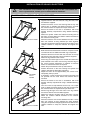
FRAMED INSTALLATIONS - FLAT ROOF FRAMES
Table 7 - Framed Installations
• Assemble the flat roof frame as shown in the diagram
•
‘TO
PH
AT
’
SE
CT
IO
N
•
FLAT ROOF FRAME
•
•
supplied with the flat roof frame kit using the bolts, nuts
and washers supplied.
Position the frame on the roof ensuring that the 'top hat'
sections are on suitable load bearing surfaces, and that
the collectors have the required 8 mm per metre rise.
Secure the frame to the roof in accordance with local
building authority requirements using suitable fastening
system.
Attach the cylinder cradle and collector mounting rails to
the frame. Loosely attach the collector retainer brackets to
the collector mounting rails.
Place the collector on the frame between the rails. If more
than one collector is being installed join them together
using the compression fittings supplied. Press down on the
collector retainer to clamp the collector and tighten the
nuts.
• Both the Reverse and Side Pitch Frames comprise of a flat
•
•
•
•
•
•
REVERSE
PITCH
FRAME
•
•
•
•
•
•
SIDE PITCH FRAME
Rinnai Australia
roof frame kit and an additional kit with leg components.
Assemble the flat roof frame with the exclusion of the top
hat sections using the bolts, nuts and washers supplied.
Attach the leg sockets to the trusses.
Fit the long and short legs into the sockets and attach the
pivot brackets to the ends. Use the long and short legs in
the correct sockets depending on whether a Reverse
Frame or a Side Pitch Frame is required.
Fasten the pivot brackets to the top hat sections.
Position the frame on the roof ensuring the cylinder and
collector load will be adequately supported.
Adjust the frame to the approximately the correct level.
Temporarily clamp in place.
If necessary, cut the excess from the legs so that they will
not protrude into the area where the collector will be
mounted.
Secure the frame to the roof in accordance with local
building authority requirements using a suitable fastening
system.
Once the frame is fully fastened to the roof, use a spirit
level to adjust the frame height on the legs ensuring that
the collectors have the required 8mm per metre rise.
Drill the legs through one of the holes in the leg sockets
and secure with the nuts and bolts supplied.
Attach the collector mounting rails to the frame. Loosely
attach the collector retainer brackets to the collector
mounting rails.
Place the collector on the frame between the rails. If more
than one collector is being installed join them together
using the compression fittings supplied. Press down on the
collector retainer to clamp the collector and tighten the
nuts.
- 25 -
Solar Split Systems Operating / Installation Manual
INSTALLATION OF SOLAR COLLECTORS
FRAMED INSTALLATIONS - CYCLONE FRAME
Assemble cyclone frame and mount collectors as described in instructions provided with cyclone
frame kit.
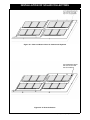
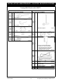
COMMERCIAL INSTALLATIONS
Commercial system comprise of multiple of 2-3 collectors joined together. Figure 22 shows the roof
spacing required for the collector sets.
Figures 23 and 24 shows the flow and return piping layout for multiple collector sets.
That the combined length of flow and return piping for each collector set is
approximately the same. This will result in even flow to all collectors and
optimum performance.
NOTE
Pipe sizing shown in table below:
Table 8 - Commercial Pipe Sizing
PIPE AND PUMP SIZING CHART - COMMERCIAL ARRAYS
Total collectors in array
Up to
Pipe sizing for solar flow and
return manifolds
Pump
10
20
30
40
50
60
70
80
90
100
DN20
DN20
DN25
DN32
DN32
DN32
DN40
DN40
DN40
DN50
20-60N 20-60N 20-60N 25-80N 25-80N 25-80N 25-80N 25-80N 25-80N 25-80N
Maximum pipe run in collector circuit (m)
Pump speed
Rinnai Australia
1
30
-
-
2
60
40
20
3
100
100
100
- 26 -
100
100
100
100
100
100
100
Solar Split Systems Operating / Installation Manual
INSTALLATION OF SOLAR COLLECTORS
Figure 22 - Commercial Collector Installation
Rinnai Australia
- 27 -
Solar Split Systems Operating / Installation Manual
INSTALLATION OF SOLAR COLLECTORS
Figure 23 - Flow and Return Lines for Commercial Systems
HOT SENSOR SHEATH
ON OUTLET OF ONE
SET OF PANELS
Figure 24 - E-Frost Collectors
Rinnai Australia
- 28 -
Solar Split Systems Operating / Installation Manual
INSTALLATION OF SOLAR COLLECTORS
COLLECTOR FITTINGS INSTALLATIONS
COLD FLOW
PIPE SUPPLIED
BY INSTALLER
1/2" TO 3/4"
UNION
STOP END
COMPRESSION
UNION
COMPRESSION
UNION
STOP END
1/2" NUT
1/2" OLIVE
RETURN PIPE
SUPPLIED BY
INSTALLER
HOT SENSOR
SHEATH
AIR BLEED
VALVE
HOT
SENSOR
LEAD
Connect the fittings to the collectors as shown in the diagrams below:
Figure 25 - Collector Fitting Details (Enduro, Equinox and Excelsior Collectors)
Rinnai Australia
- 29 -
Solar Split Systems Operating / Installation Manual
Rinnai Australia
COLD FLOW
PIPE SUPPLIED
BY INSTALLER
1/2" TO 3/4"
UNION
3/4" COMPRESSION
UNION
- 30 -
1/2" OLIVE
1/2" NUT
HOT
SENSOR
LEAD
AIR BLEED
VALVE
HEADER PIPE MUST BE AT TOP TO
ENSURE COLLECTOR OPERATION
RETURN PIPE
SUPPLIED BY
INSTALLER
HOT SENSOR
SHEATH
INSTALLATION OF SOLAR E-FROST COLLECTORS
Figure 26 - Collector Fitting Details (E-Frost Collectors)
Solar Split Systems Operating / Installation Manual
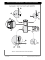
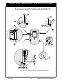
INSTALLATION & MAINTENANCE - GAS BOOSTED
OVERVIEW OF SYSTEM COMPONENTS
The range of gas boosted solar hot water systems include all the components shown in Figure 27
- 30 (refer to the appropriate Figure depending on cylinder type/size and kit on the following
pages).
The pump kit and associated plumbing connections are factory pre-assembled. All other
components and fittings will require connection on site. The gas booster and pump/controller kit may
be mounted to the front of the storage cylinder casing or in an alternative external location. In all
cases the heated outlet of the cylinder is connected to the cold water inlet of the gas booster.
GAS BOOSTER LOCATION
The gas booster is designed for ‘Outdoor” Installation only. As such, it must be located in an above
ground open air situation with natural ventilation, without stagnant areas, where gas leakage and
products of combustion are rapidly dispersed by wind and natural convection. The location must
comply with the clearances specified in AS5601.
The gas booster must be mounted on a vertical structure with the water and gas connections on the
underside pointing downwards. In most installations the gas booster is mounted directly on the
storage cylinder using two custom made mounting brackets. In all cases the heated outlet of the
cylinder is connected to cold water inlet of the gas booster.
GAS SUPPLY
The maximum gas consumption of the gas booster and the required gas pressure are shown on the
appliance data plate. If the gas pipe sizing is insufficient the customer will not get the full
performance benefit. Gas pipe sizing must consider the gas input to the gas booster as well as all
the other gas appliances on the premises. The gas meter and regulator must be specified for this
gas rate. An approved sizing chart such as the one in AS5601 should be used. An approved full flow
isolation valve and disconnection union must be fitted to the gas supply inlet of the gas booster.
Isolation valves must not be fitted directly.
HOT WATER DELIVERY TEMPERATURE
Gas boosters for use in solar hot water systems are preset to deliver a fixed temperature of 60°C in
accordance with plumbing regulations. In addition, they contain the warning stating "Rinnai Water
Controllers are NOT compatible with solar hot water installations and MUST NOT BE USED" in the
vicinity of the temperature controller connections inside the appliance.
NOTE
Gas Boosters other than models designated “S20”, “S26” or “Solar” must not be
used.
Gas Boosters marked with the text: "THIS APPLIANCE DELIVERS WATER NOT
EXCEEDING 50°C IN ACCORDANCE WITH AS 3498" are incompatible with solar hot
water systems and must not be used.
Rinnai Australia
- 31 -
Solar Split Systems Operating / Installation Manual
INSTALLATION & MAINTENANCE - GAS BOOSTED SYSTEMS
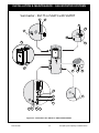
CLEARANCES
Figure 5.3 is reproduced below. Note that AS 5601-2004 was current at time of printing but may have
been superseded. It is the installer’s responsibility to ensure current requirements are met.
AS 5601 - Figure 5.3 ‘Clearances’ - Gas Booster Flue Terminal
Rinnai Australia
- 32 -
Solar Split Systems Operating / Installation Manual
INSTALLATION & MAINTENANCE - GAS BOOSTED SYSTEMS
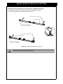
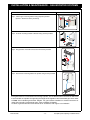
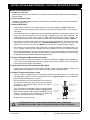
GAS BOOSTER MOUNTING
Sunmaster
Step 1. Mount upper mounting bracket using template provided.
(SG175 - SG215 are factory mounted)
Step 2. Fix lower mounting bracket to Booster using screws provided.
Step 3. Hang booster on bracket and secure with screws provided.
Step 4. Secure lower mounting bracket to cylinder using screws provided.
If the gas booster is not mounted on the storage cylinder, ensure that the wall or structure on which it is
to be mounted are capable of supporting the weight of the appliance and associated pipe work. Refer
to Table 4 for individual gas booster weights. For gas boosters installed on elevated structures or
under floors specific requirements apply, refer to AS5601 for details.
Location of gas booster flue terminal must be in accordance with Figure 5.3 of AS5601.
Rinnai Australia
- 33 -
Solar Split Systems Operating / Installation Manual
INSTALLATION & MAINTENANCE - GAS BOOSTED SYSTEMS
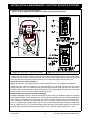
Sunmaster - 3'OR3'WITHSGPKIT
2
1
3
13
10
3
15
12
16
14
11
16
13
14
15
11
12
10
9
8
3
5
6
7
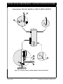
Figure 27 - Sunmaster Gas SG175 or SG215 with SGPKIT
Rinnai Australia
- 34 -
Solar Split Systems Operating / Installation Manual
INSTALLATION & MAINTENANCE - GAS BOOSTED SYSTEMS
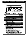
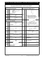
Sunmaster SG175 or SG215 with SGPKIT
Items Supplied with Cylinder
Items Supplied in SGPKIT (cont…)
1
PTR Valve
1
1
Adaptor R ¾ x Rp ½
Pump and Controller Assembly
(includes 2 x ½ Kinco nut and olive,
flow control valve and non return valve)
Temperature sensor lead (31002710)
included with assembly, but shown
separately as item 12 for clarity
39001735
3
Nipple R ¾
1
Temperature Sensor with 2 m lead
2
Part of Pump and Controller Assembly
(39001735), but shown separately
for clarity
31002710
0
Gas Booster Mounting Brackets
1 x tabs bent
26601098
1 x tabs unbent
26601096
2
Elbow ¾ Rp x ¾ G flexi
21201012
Fibre Washer ¾
17401008
Insulated Flexi Pipe 890 mm
11601070
2
Items Supplied in SGPKIT
1
¾ Kinco Olive
33001011
1
1
¾ Kinco Nut
16801018
1
2
Copper Tee
11603936
½ Kinco Olive
33001012
-
12
-
3
(*1 not needed)
2
*
½ Kinco Nut
Insulated Copper
Extension Pipe
-
1
-
1
Operation and
Installation Manual
Booster and Pump Mounting
Instruction Sheet
15401031
Cable Ties
39601036
Nipples
17201003
-
1
1
1
Saddle Clamp
Warranty booklet
RECS form
27201015
-
1
Standardsmark Sticker
15802091
11603348
15401030
22601048
2
16801012
(*1 not needed)
1
Screws
15401024
15401023
*This kit is used for a variety of installations. Items marked with an * are not needed for this particular installation
Rinnai Australia
- 35 -
Solar Split Systems Operating / Installation Manual
INSTALLATION & MAINTENANCE - GAS BOOSTED SYSTEMS
Sunmaster - 3'OR3'WITHSGPKIT2
2
1
3
13
10
3
15
12
16
14
11
17
14
16
15
11
12
8
3
6
5
Figure 28 - Sunmaster Gas SG175 or SG215 with SGPKIT2
Rinnai Australia
- 36 -
Solar Split Systems Operating / Installation Manual
INSTALLATION & MAINTENANCE - GAS BOOSTED SYSTEMS
Sunmaster SG175 or SG215 with SGPKIT2
Items Supplied with Cylinder
Items Supplied in SGPKIT2 (cont…)
1
1
Pump and Controller Assembly
PTR Valve
(includes 2 x ½ Kinco nut and olive,
flow control valve and non return valve)
Temperature sensor lead (31002710)
included with assembly, but shown
separately as item 12 for clarity
39001735
1
Adaptor R ¾ x Rp ½
1
3
Temperature Sensor with 2 m lead
Part of Pump and Controller Assembly
(39001735), but shown separately
for clarity
31002710
Nipple R ¾
1
2
Gas Booster Mounting Brackets
1 x tabs bent
26601098
1 x tabs unbent
26601096
Elbow ¾ Rp x ¾ G flexi
21201012
Fibre Washer ¾
17401008
Insulated Flexi Pipe 890 mm
11601070
Adaptor Rp ¾ x G ¾ (flexi)
16601006
Screws
22601048
Operation and
Installation Manual
15401021
Warranty booklet
15401024
RECS form
15401023
2
Items Supplied in SGPKIT2
1
1
¾ Kinco Olive
33001011
1
1
¾ Kinco Nut
16801018
-
1
-
Cold Inlet Copper T
Rinnai Australia
11603921
10
1
-
1
-
1
- 37 -
Solar Split Systems Operating / Installation Manual
INSTALLATION & MAINTENANCE - GAS BOOSTED SYSTEMS
Sunmaster SG270 - SG340 with SGPKIT 270
2
1
4
3
13
10
3
16
15
12
14
11
16
13
14
15
11
12
10
9
8
3 4 5 6
7
Figure29 - Sunmaster Gas SG270 or SG340 with SGPKIT270
Rinnai Australia
- 38 -
Solar Split Systems Operating / Installation Manual
INSTALLATION & MAINTENANCE - GAS BOOSTED SYSTEMS
Items Supplied with Cylinder
Items Supplied in SGPKIT270 (cont…)
!#$
%
&
'(
)*
#$*
+
,*
-
)%-
*
'(+'
%.%0
(
,*(
!#!
Items Supplied in SGPKIT270
!5
!*6
!*5
%%
7'!#!,
#
,&
'(
)%.%0-+'
(
%
,*(
%
:'
;
!
899
<9
&
$*6
)=
-
$*5
8%.%8
>
?@>*G
88.9
#''
#''
88.8
J
>
?@
*
>
?@
7&,
;('G
J
J
J
J
J
G*G
88.
89
&
7#
6
?
:
#
9
%%
)=
-
8%%<9
J%
0<%
0<%
0<%<
0<%
0<<
09.
&'
J
J
*
&
%.8%8
8<9
0
=G
,
(,K
G
=
,*
Rinnai Australia
- 39 -
Solar Split Systems Operating / Installation Manual
INSTALLATION & MAINTENANCE - GAS BOOSTED SYSTEMS
Sunmaster SG270 and SG340 with SGPKIT3
2
1
3
4
13
10
3
15
12
16
14
11
17
14
15
16
12
11
8
3
9
Figure 30 - Sunmaster Gas SG270 - SG340 with SGPKIT3
Rinnai Australia
- 40 -
Solar Split Systems Operating / Installation Manual
INSTALLATION & MAINTENANCE - GAS BOOSTED SYSTEMS
Sunmaster SG270 and SG340 with SGPKIT3
Items Supplied with Cylinder
Items Supplied in SGPKIT3 (cont…)
1
1
PTR Valve
1
Elbow ¾ Rp x ¾ G flexi
21201012
Fibre Washer ¾
17401008
Insulated Flexi Pipe
1080 mm
11601069
2
Adaptor R ¾ x Rp ½
3
Adaptor R ¾ x Rp ¾
1
Items Supplied in SGPKIT3
1
R ¾ Nipple
17201005
1
2
Cold Inlet Copper T
11603921
Gas Booster Mounting Brackets
1 x tabs bent
26601098
1 x tabs unbent
26601096
1
G3/4 (Comp) x R ¾ union
32201713
1
Adaptor Rp ¾ x G ¾ (flexi)
16601006
Screws
22601048
Operation and
Installation Manual
15401021
1
Pump and Controller Assembly
(includes 2 x ½ Kinco nut and olive,
flow control valve and non return valve)
Temperature sensor lead (31002710)
included with assembly, but shown
separately as item 12 for clarity
39001735
-
14
1
-
1
Warranty booklet
15401024
-
1
RECS form
15401023
-
1
Gas Booster
Mounting Template
15401034
1
Temperature Sensor with 2 m lead
Part of Pump and Controller Assembly
(39001735), but shown separately
for clarity
31002710
Rinnai Australia
- 41 -
Solar Split Systems Operating / Installation Manual
INSTALLATION & MAINTENANCE - GAS BOOSTED SYSTEMS
INSTALLATION PROCEDURE
Install Solar Collectors
Position and install the solar collectors in accordance with the section ‘INSTALLATION SOLAR
COLLECTORS”.
1. Position Storage Cylinder
Position the hot water storage cylinder on a level base in accordance with the section ‘STORAGE
CYLINDER LOCATION’.
2. Connect PTR Valve
•
Connect the PTR Valve in the location shown in the relevant diagram of Figures 27 to 30.
Leave the valve outlet pointing down. Tighten the valve using the spanner flats - never use the
valve body.
•
The PTR Valve must be adequate for the thermal loading applied to the storage cylinder. In the
case of gas boosted systems, the thermal load is applied only by the solar collectors. The
continuous flow hot water heater does not apply thermal load to the storage cylinder. The potential
solar output for the solar collectors at PTR Valve relief conditions is listed in Table 3.
•
The PTR Valve pressure ratings vary according the cylinder specifications. The maximum heater
input rating is 10.0 kW. The PTR valve rating MUST EXCEED the total input from the solar
collectors. If it does not, the PTR valve MUST be exchanged for a model of higher capacity.
•
For example, for a gas boosted solar system with 3 x SP200A collectors, the thermal load is 3 x
1.25 = 3.75 kW. This is less than 10.0 kW, hence the supplied PTR valve is of sufficient capacity.
•
Use Teflon thread tape on the valve, never use hemp or other sealing materials. Ensure the tape
does not protrude past the end of the thread, which could result in it hanging over the end of the
thread and blocking the water passage through the valve.
3. Mount Gas Booster
Mount the gas booster in accordance with the section ‘GAS BOOSTER LOCATION & MOUNTING’.
4. Connect Fittings and Mount Pump Assembly
Connect fittings and pipe work as shown in the relevant diagram in Figures 27 to 30. Remove
cover of pump box and attach pump box to cylinder using screws provided. DO NOT connect the
power lead to power supply at this stage.
5. Install and Connect Flow and Return Pipe Work
Connect flow and return pipe work between storage cylinder and solar collector. Ensure that
suitable pipe and insulation is used as described in the section "WATER PIPES".
6. Connect Temperature Sensor Leads
•
The hot (longer) temperature sensor lead should be fitted into
the air bleed / hot sensor lead assembly at the collector hot
return connection as shown in Figures 25 to 26. It must be
sealed in place with thermoplastic putty or silicone.
•
Run the lead down the solar return pipe and connect it to the
connection within the pump and controller assembly as shown
in the diagram. Ensure the lead is protected from light. Figure
34 - Temperature Sensor Leads
•
The cold (shorter) temperature sensor lead should be fitted as
shown in the relevant diagram in Figures 27 to 30. It must be
sealed in place with thermoplastic putty or silicone. The plug is
then connected to the pump and controller assembly as shown
in the diagram.
•
Replace Pump Assembly Cover.
hot sensor connection
in pump box.
cold sensor connection
in pump box.
hot sensor lead
connection
cold sensor lead
connection
Figure 3 - Temperature Sensor Leads
IT IS IMPORTANT THAT THESE PROBES ARE INSTALLED AS SPECIFIED. FAILURE
TO DO SO WILL LEAD TO MALFUNCTION OR LACK OF HOT WATER.
NOTE
Rinnai Australia
- 42 -
Solar Split Systems Operating / Installation Manual
INSTALLATION & MAINTENANCE - GAS BOOSTED SYSTEMS
7. Cold Water Supply
•
Connect cold water supply to the inlet ‘T’. Ensure that the relevant valves as described in the
section “VALVES AND FITTINGS” are fitted.
•
Purge the cold water supply lines to remove air and swarf before final connection.
8. Relief Drain Lines
•
Independent 15 mm copper pipes must be fitted to the drain outlets of the PTR and ECV. Each pipe
must be open to atmosphere and run with a continual downward grade in a frost free environment
to a visible discharge point. Drain lines must not exceed 9 metres in length.
•
Valves or other restrictions must not be placed in the relief valve drain outlet line.
Some water will drip from the drain lines during heating of the water in the storage
cylinder. It is recommended to discharge directly above a drain.
NOTE
9. Hot Water Discharge
•
Connect the hot water outlet of the gas booster to the pipe work supplying hot water to the
premises.
A temperature limiting device may be required as detailed in the section “HOT
WATER DELIVERY TEMPERATURE”.
WARNING
10. Connect Gas to Booster
•
Connect a suitable gas supply and isolating valve to the gas booster. Follow instructions supplied
with gas booster. Keep gas booster isolated at this stage.
FILLING THE SYSTEM
CAUTION
Ensure building occupants are warned to stay clear of the solar system components,
building perimeter and roof since hot water or steam may be discharged from pipes
or components.
1. Ensure the electric power supplies to the water heater and pump kit are switched ‘OFF’.
2. Ensure the gas supply to the continuous flow water heater is isolated.
3. Turn ‘ON’ the hot water tap at the sink. Open the stop cock in the cold water mains supply line.
4. The entire system will now be filled with cold water. Most air will be dispelled through the tap. Some air
needs to be bled from the air bleed valve on the collectors.
5. Turn ‘OFF’ the hot tap at the sink when water flows freely without air bubbles or air bursts. Check all
connections for leakage and tighten if necessary. This applies especially to fittings in positions not
easily assessed such as near the solar collectors. Operate the easing gear of both the PTR and ECV
valves at the storage cylinder to ensure these valves are functional.
CAUTION
If leaks are detected the system must be drained and leaks repaired before the
system is refilled. If this is necessary, cover the solar collectors with packaging
cardboard or a tarp to prevent them from heating which could result in steam or hot
water being discharged from fittings.
Rinnai Australia
- 43 -
Solar Split Systems Operating / Installation Manual
INSTALLATION & MAINTENANCE - GAS BOOSTED SYSTEMS
CHECKING SOLAR PUMP OPERATION
1. Ensure hot and cold sensors are connected as shown Figure 31.
2. Activate power supply.
3. Pumps will operate when solar energy is available to be collected. Pump operation can be checked by
placing the end of a screw driver to the pump body and the other end of the screw driver near your
ear.
The dip switches within the pump control box should not need to be adjusted.
NOTE
If the solar pump does not activate the system can still be commissioned as detailed in
these instructions, but solar preheating will not be available until the pump and
controller operate.
ADJUSTING FLOW CONTROL VALVE
The purpose of the flow control valve is to allow the water flow
rate through the collector collectors and storage cylinder to be
controlled to optimise the performance of the system. The
optimum flow rate for the system will depend on the type of
system (electric or gas boost), the number of collector
collectors, and the location of the installation (see the solar
zone shown in Figure 32).
Figure 32 - Australian Solar Zones
The flow control valve needs to be adjusted while the pump is
operating. The flow rate valve is read at the bottom of the
baffle float as shown in Figure 33 Using a flat bladed screw
driver turn the screw on the valve until the value from Table 9
is achieved.
Figure 33 - Adjusting Flow Control Valve
The installer will need to set the flow rate to the value shown in Table 9 below.
Table 9 - Optimum Flow Rate (Litres/min).
Gas Boosted
Rinnai Australia
No. of Collectors
Zones
1, 2 & 3
Zone 4
1
0.50
0.50
2
1.25
1.25
3
2.10
2.10
- 44 -
Solar Split Systems Operating / Installation Manual
INSTALLATION & MAINTENANCE - GAS BOOSTED SYSTEMS
PRE SOLAR HEATING CHECKS
Before commencing solar heating of the water in the system ensure the following actions have been
completed:
Solar Collectors
1. Are the solar collectors installed with the correct slope and orientation to the sun?
2. Is the installation finished neatly with the roof made good, all tiles and flashings in place?
3. Are the bolts tight on the roof framework?
4. Are all solar collector straps fitted and correctly anchored to the roof structure?
5. If leak testing completed and successful, have any covers been removed from the solar collectors?
6. Has operation of the solar pump been checked?
7. Have the hot and cold sensors and leads been positioned and connected correctly?
Gas Booster
1. Ensure the gas supply is isolated. Remove the test point screw located on the gas inlet connection
and attach a pressure gauge.
2. Turn on the electrical power to the gas booster only (not the solar pump kit) and turn on the gas
supply.
3. Ensure the cold water inlet ('trio') valve on the storage cylinder inlet is open. Open all available hot
water taps.
4. Operate ALL other gas appliances at their maximum gas rate, in accordance with manufacturers
instructions.
Ensure building occupants do not have access to hot water outlets during this
procedure.
CAUTION
5. With all gas appliances in operation at the maximum gas rate, the pressure should read between 1.13
- 3.0 kPa on Natural Gas. On LPG the pressure should be 2.75 - 3.0 kPa. If the pressure is lower, the
gas supply is inadequate and the appliance will not operate to specification. It is the installers
responsibility to check the gas meter, service regulator and pipe work for correct operation/ sizing &
rectify as required. Note that the gas regulator on the appliance is electronically controlled and factory
pre-set. Under normal circumstances it DOES NOT need adjustment during installation. Make
adjustments only if the gas booster is not operating correctly and all other possible causes for
incorrect operation have been eliminated. Instructions for gas pressure setting are located in the
pocket behind the front cover of the gas booster.
6. Close the hot water taps including the shower.
7. Check the hot water delivery temperature by placing a suitable thermometer at the hot water outlet
closest to the gas booster. This is usually the hot water outlet in the kitchen. The delivery temperature
should be greater than 55°C (this temperature allows for heat losses in pipe work). If the delivery
temperature at the hot water outlet is lower than 55°C, check the delivery temperature at the outlet of
the gas booster. It should be within 2°C of the set point, usually 60°C. If not, refer to the section 'Hot
Water Delivery temperature'.
8. Close the cold water inlet ('trio') valve on the storage cylinder inlet and inspect and clean the strainer.
Repeat for the strainer connected at the inlet of the gas booster. This procedure may need to be
repeated to ensure the strainers remains clear, especially on new installations.
9. Confirm the hot water delivery temperature from the gas booster. This is done by checking the hot
water delivery temperature at an untempered outlet close to the water heater. This is usually the hot
water outlet in the kitchen. The untempered hot water delivery should be between 55°C & 60°C.
Rinnai Australia
- 45 -
Solar Split Systems Operating / Installation Manual
INSTALLATION & MAINTENANCE - GAS BOOSTED SYSTEMS
Temperature Limiting Devices
1. Commission any temperature limiting devices in accordance with the instructions supplied by the
manufacturer.
2. Confirm the hot water delivery temperature at a tempered water outlet. Tempered water outlets should
be those supplying areas primarily used for the purposes of personal hygiene such as bathrooms.
The hot water delivery temperature should not exceed 50°C or 45°C as detailed in the section ‘Hot
water delivery temperature’.
SOLAR HEATING
1. Remove any cardboard or tarp covers that may have been placed over the solar collectors to prevent
them from heating water during installation and commissioning.
2. Activate electrical power to both the gas booster and solar pump and controller. Solar heating of the
water in the cylinder will now commence when sufficient solar reduction is available.
FINISHING THE INSTALLATION
After testing is completed explain to the householder the functions and operation of solar water heater
components. Also explain to the householder the importance of carrying out Maintenance as per
separate warranty document.
Leave this Manual with the householder.
Remind the householder to complete the 'Warranty Certificate' provided in the separate warranty
document.
DRAINING INSTRUCTIONS
1. The power supply to the gas booster and pump controller must be switched off and fuse(s) removed.
2. Close the cold water mains supply stop cock.
3. Open a hot tap to relieve pressure.
4. Disconnect the hot outlet near the top of the storage cylinder.
5. Disconnect the cold inlet near the bottom of the storage cylinder.
6. Disconnect the connection between the solar 'flow pipe' and solar pump.
7. Disconnect the connection between the solar 'return pipe' and the cylinder.
8. The cylinder and solar collectors will now drain completely.
Rinnai Australia
- 46 -
Solar Split Systems Operating / Installation Manual
INSTALLATION & MAINTENANCE - ELECTRIC BOOSTED SYSTEMS
OVERVIEW OF SYSTEM COMPONENTS
The range of electric boosted solar hot water systems include all the components shown in (Refer
to the appropriate figure depending on cylinder type / size and kit).
The pump kit and associated plumbing connections are factory pre-assembled. All other components
and fittings will require connection on site.
ELECTRIC SUPPLY
Electrical connection must be carried out by a qualified person and in accordance with AS3000 ‘Wiring
Rules’ and local authority requirements.
All electrically boosted solar hot water heating elements must be connected to an independent, fused,
AC 240V 50 Hz power supply with an isolating switch installed at the switch board. Ensure the
household wiring to the system is capable of withstanding the system electrical load (refer to
specifications for electrical load details). Twin element models are factory wired for ‘non’
simultaneous’ operation.
The solar pump kit requires an AC 240V power supply from a 10A earthed power point adjacent to the
storage cylinder. For outdoor installations this power point must be weatherproof. This power supply
must be independent from the power supply to any heating elements.
HOT WATER STORAGE AND DELIVERY TEMPERATURES
Australian Standards require a minimum storage cylinder thermostat set point of 60°C.
Rinnai Australia
- 47 -
Solar Split Systems Operating / Installation Manual
INSTALLATION & MAINTENANCE - ELECTRIC BOOSTED SYSTEMS
Sunmaster SE160, SE200 or SE315 WITH SEPKIT
2
1
3
3
11
10
12
9
8
3 4 5 6
7
Figure 34 - Sunmaster Electric SE160, SE200 or SE315 with SEPKIT
Rinnai Australia
- 48 -
Solar Split Systems Operating / Installation Manual
INSTALLATION & MAINTENANCE - ELECTRIC BOOSTED SYSTEMS
Sunmaster SE160, SE200 or SE315 with SEPKIT
Items Supplied with Cylinder
Items Supplied in SEPKIT (cont…)
1
PTR Valve
1
1
Pump and Controller Assembly
(includes 2 x ½ Kinco nut and olive,
flow control valve and non return valve)
Temperature sensor lead (31002710)
included with assembly, but shown
separately as item 12 for clarity
39001735
Adaptor R ¾ x Rp ½
3
Adaptor R ¾ x Rp ¾
Items Supplied in SEPKIT
1
R ¾ Nipples
17201003
(*1 not needed)
*
1
¾ Kinco Olive
2
33001011
1
¾ Kinco Nut
16801018
Copper T
11603936
½ Kinco Olive
33001012
1
2
Temperature Sensor with 2 m lead
Part of Pump and Controller Assembly
(39001735), but shown separately
for clarity
31002710
2
G ¾ (comp) x Rp ¾ elbow
21201026
Screws
22601048
Cable Ties
39601036
15401030
6
-
3
-
1
Operation and
Installation Manual
-
1
Warranty booklet
(*1 not needed)
2
½ Kinco Nut
16801012
15401024
(*1 not needed)
-
1
RECS form
1
15401023
Insulated Copper
Extension Pipe
-
1
Standardsmark Sticker
11603348
*This kit is used for a variety of installations. Items marked with an * are not needed for this particular installation
Rinnai Australia
- 49 -
15802091
Solar Split Systems Operating / Installation Manual
INSTALLATION & MAINTENANCE - ELECTRIC BOOSTED SYSTEMS
Sunmaster SE160, SE200 or SE315 with USKIT1
2
1
3
3
11
12
8
3
9
Figure 35 - Sunmaster Electric SE160, SE200 or SE315 with USKIT1
Rinnai Australia
- 50 -
Solar Split Systems Operating / Installation Manual
INSTALLATION & MAINTENANCE - ELECTRIC BOOSTED SYSTEMS
Sunmaster SE160, SE200 or SE315 with USKIT1
Items Supplied with Cylinder
Items Supplied in USKIT1
1
1
PTR Valve
1
Adaptor R¾ x Rp½
3
Cold Inlet Copper T
11603921
G3/4 (Comp) x R ¾ union
32201713
1
Adaptor R¾ x Rp¾
1
Pump and Controller Assembly
(includes 2 x ½ Kinco nut and olive,
flow control valve and non return valve)
Temperature sensor lead (31002710)
included with assembly, but shown
separately as item 12 for clarity
39001735
1
Temperature Sensor with 2 m lead
Part of Pump and Controller Assembly
(39001735), but shown separately
for clarity
31002710
-
6
-
1
-
Rinnai Australia
- 51 -
1
1
Screws
Operation and
Installation Manual
Warranty booklet
RECS form
22601048
15401021
15401024
15401023
Solar Split Systems Operating / Installation Manual
INSTALLATION & MAINTENANCE - ELECTRIC BOOSTED SYSTEMS
Prestige Electric with USKIT
2
1
11
4
10
12
8
9
3
Figure 36 - Split Prestige Electric with USKIT1
Rinnai Australia
- 52 -
Solar Split Systems Operating / Installation Manual
INSTALLATION & MAINTENANCE - ELECTRIC BOOSTED SYSTEMS
Prestige MkII Electric with USKIT1
Items Supplied with Cylinder
Items Supplied in USKIT1
1
PTR Valve
11004784
1
1
Hot outlet T
19001018
Cold Inlet Copper T
11603921
1
T ¾ Rp
19001011
1
1
1
Nipple R ¾
17201005
250 mm Sheath
Thermocouple
10204721
G3/4 (Comp) x R ¾ union
32201713
1
Pump and Controller Assembly
(includes 2 x ½ Kinco nut and olive,
flow control valve and non return valve)
Temperature sensor lead (31002710)
included with assembly, but shown
separately as item 12 for clarity
39001735
1
Temperature Sensor with 2 m lead
Part of Pump and Controller Assembly
(39001735), but shown separately
for clarity
31002710
Rinnai Australia
- 53 -
-
6
-
1
-
1
1
Screws
Operation and
Installation Manual
Warranty booklet
RECS form
22601048
15401021
15401024
15401023
Solar Split Systems Operating / Installation Manual
INSTALLATION & MAINTENANCE - ELECTRIC BOOSTED SYSTEMS
INSTALLATION PROCEDURE
1. Install Solar Collectors
Position and install the solar collectors in accordance with the section ‘INSTALLATION OF SOLAR
COLLECTORS’.
2). Position Storage Cylinder
Position the hot water storage cylinder on a level base in accordance with the section “STORAGE
CYLINDER LOCATION”
3. Connect PTR Valve
•
Connect the PTR Valve in the location shown in the relevant diagram of Figures 34 to 36.
Leave the valve outlet pointing down. Tighten the valve using the spanner flats - never use the
valve body.
•
The PTR Valve must be adequate for the thermal loading applied to the storage cylinder. In the
case of gas boosted systems, the thermal load is applied only by the solar collectors. The
continuous flow hot water heater does not apply thermal load to the storage cylinder. The
potential solar output for the solar collectors at PTR Valve relief conditions is listed in Table 3.
•
The PTR Valve pressure ratings vary according the cylinder specifications. The maximum heater
input rating is 10.0 kW. The PTR valve rating MUST EXCEED the total input from the solar
collectors. If it does not, the PTR valve MUST be exchanged for a model of higher capacity.
•
For example, for a gas boosted solar system with 3 x SP200A collectors, the thermal load is 3 x
1.25 = 3.75 kW. This is less than 10.0 kW, hence the supplied PTR valve is of sufficient capacity.
•
Use Teflon thread tape on the valve, never use hemp or other sealing materials. Ensure the tape
does not protrude past the end of the thread, which could result in it hanging over the end of the
thread and blocking the water passage through the valve.
4. Connect Fittings and Mount Pump Assembly
•
Connect fittings and pipe work as shown in the relevant diagram in Figures 34 to 36. Remove
cover of pump box and attach pump box to cylinder using screws provided. Do not connect the
power lead to power supply at this stage.
5. Install and Connect Flow and Return Pipe Work
•
Connect flow and return pipe work between storage cylinder and solar collector. Ensure that
suitable pipe and insulation is used as described in the section "WATER PIPES".
6. Connect Temperature Sensor Leads
•
The hot (longer) temperature sensor lead should be fitted into the air bleed / hot sensor lead
assembly at the collector hot return connection as shown in Figure 25 to 26. It must be sealed in
place with thermoplastic putty or silicone.
•
Run the lead down the solar return pipe and connect it to
the connection within the pump and controller assembly
as shown in the diagram below. Ensure the lead is
protected from light.
•
•
The cold (shorter) temperature sensor lead should be
fitted as shown in the relevant diagram in Figures 34 to
36. It must be sealed in place with thermoplastic putty or
silicone. The plug is then connected to the pump and
controller assembly as shown in the diagram.
Replace pump assembly cover.
hot sensor connection
in pump box.
cold sensor connection
in pump box.
hot sensor lead
connection
cold sensor lead
connection
Figure 3 - Temperature Sensor Leads
IT IS IMPORTANT THAT THESE PROBES ARE INSTALLED AS SPECIFIED. FAILURE TO DO SO WILL LEAD TO MALFUNCTION OR LACK OF HOT WATER.
NOTE
Rinnai Australia
- 54 -
Solar Split Systems Operating / Installation Manual
INSTALLATION & MAINTENANCE - ELECTRIC BOOSTED SYSTEMS
7. Cold Water Supply
•
Connect cold water supply to the inlet ‘T’. Ensure that the relevant valves as described in the
section “VALVES AND FITTINGS” are fitted.
•
Purge the cold water supply lines to remove air and swarf before final connection.
8. Relief Drain Lines
•
Independent 15 mm copper pipes must be fitted to the drain outlets of the PTR and ECV. Each
pipe must be open to atmosphere and run with a continual downward grade in a frost free
environment to a visible discharge point. Drain lines must not exceed 9 metres in length.
•
Valves or other restrictions must not be placed in the relief valve drain outlet line.
Some water will drip from the drain lines during heating of the water in the storage
cylinder. It is recommended to discharge directly above a drain.
NOTE
9). Hot Water Discharge
•
Connect the hot water outlet of the storage cylinder to the pipe work supplying hot water to the
premises.
A temperature limiting device may be required as detailed in the section “HOT
WATER DELIVERY TEMPERATURE”.
WARNING
10).Electrical Supply Connections
The power supply to the heating elements and pump kit must not be activated until the
system is filled with water.
WARNING
•
Twin element storage cylinders are wired for non simultaneous operation. The electric supply
should be ‘Off-Peak’ (overnight) to the bottom heating unit and continuous to the top heating unit.
•
The power supply to a single element model can be either Off-Peak (overnight), Extended OffPeak (overnight and day) or continuous, depending on the tariffs available from the local
electricity supply authority. The Off-Peak (overnight) power supply minimises the cost of any
required electric boosting. Discuss power supply requirements with the end user and electricity
supply authority as required.
Rinnai Australia
- 55 -
Solar Split Systems Operating / Installation Manual
INSTALLATION & MAINTENANCE - ELECTRIC BOOSTED SYSTEMS
11).Connections for single element heaters Figures 17 & 18 shows the wiring detail for single and twin element heaters.
Figure 37 - Wiring detail - single element heaters
Figure 38 - Wiring detail for twin element heaters
A flexible 20 mm conduit is required for the electrical cable to the storage cylinder. The conduit is to be
connected to the unit with a 20mm terminator. Connect the power supply wires directly to the terminal
block and earth tab connections ensuring there are no excess wire loops inside the front cover.
Connections for twin element heaters
Figure 38 - shows the wiring detail for twin element heaters wired for non simultaneous operation.
A flexible 20 mm conduit is required for the electrical cable to the storage cylinder. All wiring passes
through the lower entry. The conduit is to be connected to the unit with a 20 mm terminator. A common
neutral is used. Connect the power supply wires directly to the terminal block and earth tab connections
ensuring there are no excess wire loops inside the front cover.
Heating Element Thermostat Temperature Settings
Australian Standards require a minimum thermostat set point of 60°C to inhibit the growth of Legionella
Pneumophilia bacteria. These standards also require that the thermostat set point of water heaters fitted
with an upper (or booster) element is at least 10°C below the thermostat set point of the lower element.
In the interests of durability, the thermostat set point for storage cylinders should not exceed 70°C.
Hence, in systems with a single heating element only the thermostat set point should be at least 60°C
and no greater than 70°C. In systems with both a lower and upper (or booster) element, the thermostat
set point of the lower element should be between 60° and 70°C and the upper element 50°C - 60°C.
Rinnai Australia
- 56 -
Solar Split Systems Operating / Installation Manual
INSTALLATION & MAINTENANCE - ELECTRIC BOOSTED SYSTEMS
FILLING THE SYSTEM
CAUTION
Ensure building occupants are warned to stay clear of the solar system components,
building perimeter and roof since hot water or steam may be discharged from pipes
or components.
1. Ensure the electric power supplies to the water heater and pump kit are switched ‘OFF’.
2. Ensure the gas supply to the continuous flow water heater is isolated.
3. Turn ‘ON’ the hot water tap at the sink. Open the stop cock in the cold water mains supply line.
4. The entire system will now be filled with cold water. Most air will be dispelled through the tap. Some air
needs to be bled from the air bleed valve on the collectors.
5. Turn ‘OFF’ the hot tap at the sink when water flows freely without air bubbles or air bursts. Check all
connections for leakage and tighten if necessary. This applies especially to fittings in positions not
easily assessed such as near the solar collectors. Operate the easing gear of both the PTR and ECV
valves at the storage cylinder to ensure these valves are functional.
CAUTION
If leaks are detected the system must be drained and leaks repaired before the
system is refilled. If this is necessary, cover the solar collectors with packaging
cardboard or a tarp to prevent them from heating which could result in steam or hot
water being discharged from fittings.
CHECKING SOLAR PUMP OPERATION
1. Ensure hot and cold sensors are connected as shown in Figure 31.
2. Activate power supply.
3. Pumps will operate when solar energy is available to be collected. Pump operation can be checked by
placing the end of a screw driver to the pump body and the other end of the screw driver near your ear. The dip switches within the pump control box should not be adjusted.
NOTE
If the solar pump does not activate the system can still be commissioned as detailed
in these instructions, but solar preheating will not be available until the pump and
controller operate.
ADJUSTING FLOW CONTROL VALVE
The purpose of the flow control valve is to allow the water flow
rate through the collector collectors and storage cylinder to be
controlled to optimise the performance of the system. The
optimum flow rate for the system will depend on the type of
system (electric or gas boost), the number of collector
collectors, and the location of the installation (see the solar
zone shown in Figure 32).
Figure 32 - Australian Solar Zones
The flow control valve needs to be adjusted while the pump is
operating. The flow rate valve is read at the bottom of the baffle
float as shown in Figure 33. Using a flat bladed screw driver
turn the screw on the valve until the value from Table 10 is
achieved.
Figure 33 - Adjusting Flow Control Valve
The installer will need to set the flow rate to the value shown in Table 10 below.
Rinnai Australia
- 57 -
Solar Split Systems Operating / Installation Manual
INSTALLATION & MAINTENANCE - ELECTRIC BOOSTED SYSTEMS
Table 10 - Optimum Flow Rate (Litres/min).
No. of Collectors
Zones
1, 2 & 3
Zone 4
1
0.50
0.50
2
1.00
0.65
3
1.25
1.00
Electric Boosted
PRE SOLAR HEATING CHECKS
Before commencing solar heating of the water in the system ensure the following actions have been
completed:
Solar Collectors
1. Are the solar collectors installed with the correct slope and orientation to the sun?
2. Is the installation finished neatly with the roof made good, all tiles and flashings in place?
3. Are the bolts tight on the roof framework?
4. Are all solar collector straps fitted and correctly anchored to the roof structure?
5. If leak testing completed and successful, have any covers been removed from the solar collectors?
6. Has operation of the solar pump been checked?
7. Have the hot and cold sensors and leads been positioned and connected correctly?
Electric Heating Elements
1. In systems with a single heating element only has the thermostat set point been set to at least 60°C
and no greater than 70°C.
2. In systems with both a lower and upper (or booster) element, has the thermostat set point of the lower
element been set to at least 60° and no greater than 70°. Has the upper element been set to 10° less
than the lower element? .
Temperature Limiting Devices
1. Commission any temperature limiting devices in accordance with the instructions supplied by the
manufacturer.
2. Confirm the hot water delivery temperature at a tempered water outlet. Tempered water outlets
should be those supplying areas primarily used for the purposes of personal hygiene such as
bathrooms. The hot water delivery temperature should not exceed 50°C or 45°C as detailed in the
section ‘Hot water delivery temperature’.
SOLAR HEATING
1. Remove any cardboard or tarp covers that may have been placed over the solar collectors to prevent
them from heating water during installation and commissioning.
2. Activate electrical power to both the gas booster and solar pump and controller. Solar heating of the
water in the cylinder will now commence when sufficient solar reduction is available.
Auxiliary Energy Supply
1. Connect the electrical element to the power supply (off peak if available).
2. When the system is full of water turn on electrical supply to element.
FINISHING THE INSTALLATION
After testing is completed explain to the householder the functions and operation of solar water heater
components. Also explain to the householder the importance of carrying out Maintenance as per
separate warranty document.
Leave this Manual with the householder.
Remind the householder to complete the 'Warranty Certificate' provided in the separate warranty
document.
DRAINING INSTRUCTIONS
Rinnai Australia
- 58 -
Solar Split Systems Operating / Installation Manual
INSTALLATION & MAINTENANCE - ELECTRIC BOOSTED SYSTEMS
1. The power supply to the element and pump controller must be switched off and fuse(s) removed.
2. Close the cold water mains supply stop cock.
3. Open a hot tap to relieve pressure.
4. Disconnect the hot outlet near the top of the storage cylinder.
5. Disconnect the cold inlet near the bottom of the storage cylinder.
6. Disconnect the connection between the solar 'flow pipe' and solar pump.
7. Disconnect the connection between the solar 'return pipe' and the cylinder.
8. The cylinder and solar collectors will now drain completely.
Rinnai Australia
- 59 -
Solar Split Systems Operating / Installation Manual
NOTES
NOTES
CONTACT INFORMATION
Australia Pty. Ltd.
Internet: www.rinnai.com.au
E-mail: [email protected]
ABN 74 005 138 769
Head Office
10-11 Walker Street,
Braeside, Victoria 3195
P.O. Box 460
Tel: (03) 9271 6625
Fax: (03) 9271 6622
Spare Parts & Technical Info
Tel: 1300 555 545*
Fax: 1300 300 141*
Rinnai has a Service and Spare Parts network with personnel who are fully trained
and equipped to give the best service on your Rinnai appliance. If your appliance
requires a service, please call our National Help Line.
*Cost of a local call Higher from mobile or public phones.
Hot Water Service Line
Tel: 1800 000 340
123 45678 90123 4
- 63 -
RA Solar Split Systems Op Inst Manual Issue 6, 23/3/10
15401021
National Help Line