1
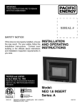
IMPORTANT: THESE INSTRUCTIONS ARE TO REMAIN WITH THE HOMEOWNER INSTALLATION AND OPERATING INSTRUCTIONS SERIAL # SAFETY NOTICE If this stove is not properly installed, a house fire may result. For your safety, follow the installation instructions. Contact local building or fire officials about restrictions and installation inspection requirements in you area. TESTED and LISTED to ULC S628 / UL 1482 Meets the U.S. Environmental Protection Agency's May 2015 Particulate Emission Standards 140515-20 ©PACIFIC ENERGY FIREPLACE PRODUCTS LTD. - 2015 Model: TN20 INSERT Series: A TN20 INSERT-A 5055.553-A Contents Safety............................................................................................. 3 Dimensions............................................................................................. 3 Clearances.................................................................................... 3 Masonry or Factory Built Fireplace....................................................... 3 Chimney Smoke and Creosote Formation........................................... 4 Chimney Fires...................................................................................... 4 Avoiding a Chimney Fire...................................................................... 4 In Case of a Chimney Fire.................................................................... 4 Heat Output Calculation....................................................................... 4 Proper Draft.......................................................................................... 4 Ash Removal........................................................................................ 4 Disposal of Ashes................................................................................. 4 Operation..................................................................................... 5 Wood Selection.................................................................................... 5 How to Test Your Wood......................................................................... 5 Normal Operation................................................................................. 5 Restarting After Extended or Overnight Burns..................................... 5 Over Firing............................................................................................ 5 Maintenance................................................................................ 6 Blower Maintenance............................................................................. 6 Baffle Tubes/Board Removal................................................................ 6 Blower Removal................................................................................... 7 Maintenance Checks.................................................................. 8 Installation................................................................................... 9 Fireplace Specifications....................................................................... 9 Into a Masonry Fireplace...................................................................... 9 Full Flue Liner - (Required in Canada)................................................11 Direct Flue Connection - (USA only)..................................................11 Into a Factory Built Fireplace...............................................................12 Combustion Air....................................................................................12 Leveling Legs......................................................................................12 Surround Assembly and Installation....................................................12 Blower.......................................................................................... 13 Blower Operation...................................................................................13 Electrical Supply....................................................................................13 Firebrick Installation................................................................... 14 Troubleshooting.......................................................................... 15 Replacement Parts................................................................................16 Warranty Information.................................................................. 17 Label......................................................................................................19 PLEASE SAVE THESE INSTRUCTIONS This manual describes the installation and operation of the True North, TN20 INSERT wood heater. This heater meets the 2015 U.S. Environmental Protection Agency's crib wood emission limits for wood heaters sold after May 15, 2015. Under specific test conditions this heater has been shown to deliver heat at rates ranging from 10,700 to 32,900 Btu/hr. NOTE: WE STRONGLY RECOMMEND THAT SMOKE AND CARBON MONOXIDE DETECTORS BE INSTALLED IN THE AREA WHERE THE HEATER IS TO BE INSTALLED. If smoke detectors have been previously installed, you may notice that they are operating more frequently. This may be due to curing of stove paint or fumes caused by accidentally leaving the fire door open. Do not disconnect the detectors. SAFETY NOTICE: If this stove is not properly installed, a house fire may result. For your safety, follow the installation instructions. Contact local building or fire officials about restrictions and installation inspection requirements in you area. Please read this entire manual before you install and use your new room heater. Failure to follow instructions may result in property damage, bodily injury, or even death. 2 ©PACIFIC ENERGY FIREPLACE PRODUCTS LTD. TN 20 INSERT-A 140515-20 Safety READ ALL INSTRUCTIONS BEFORE INSTALLING AND USING THIS APPLIANCE. FAILURE TO FOLLOW INSTRUCTIONS MAY RESULT IN PROPERTY DAMAGE, BODILY INJURY, OR EVEN DEATH. We strongly recommend that smoke detectors be installed. If smoke detectors have been previously installed, you may notice that they are operating more frequently. This may be due to curing of stove paint or fumes caused by accidentally leaving the fire door open. Do not disconnect the detectors. If necessary, relocate them to reduce their sensitivity. SAFETY NOTICE: If this stove is not properly installed, a house fire may result. For your safety, follow the installation directions. Consult local building or fire officials about restrictions and installation inspection requirements in your area. The services of a competent installer, certified by the Wood Energy Technical program (WETT) - in Canada, Hearth Education Foundation (HEARTH) - in U.S.A. (or equivalent) are strongly recommended. Clearances Masonry or Factory Built Fireplace The minimum required clearances to surrounding combustible materials when installed into a masonry or factory built fireplace are listed below and in Fig. #1. Minimum Clearances to Combustibles Adjacent Sidewall*........................................12 in.(305 mm) Side Facing*..............................................8 1/2 in.(216 mm) *(measured from side of stove) Mantel / Top Facing (measured from firebox top)........................15 in.(380 mm) Ceiling. (from base of unit).........................................54 in.(1.37m) Dimensions 25 1/8" 640mm 17 7/8" 21 1/2" 36" 455mm 546mm 914mm 20 1/8" 18 5/8" 473mm 12 1/2" 26" 511mm 318mm 660mm 19 7/8" 505mm 21 3/8" 543mm Fig. # 1 15” 380mm SIDE FACING AND ADJACENT WALL MEASURED FROM SIDE OF STOVE nt e jac d A all W 140515-20 12” 305mm 8” 203mm TN 20 INSERT-A Side Facing Mantel or Top Facing MINIMUM 54” FROM BASE OF UNIT TO CEILING MANTEL DISTANCE MEASURED FROM TOP OF FIREBOX 8 1/2” 216mm Hearth USA:16” CANADA: 18” (457mm) ©PACIFIC ENERGY FIREPLACE PRODUCTS LTD. 3 In Case of a Chimney Fire Chimney Smoke and Creosote Formation When wood is burned slowly, it produces tar and other organic vapours, which combine with expelled moisture to form creosote. The creosote vapours condense in the relatively cool chimney flue of a slow burning fire. As a result, creosote residue accumulates on the flue lining. When ignited, this creosote makes an extremely hot fire. The chimney connector and chimney should be inspected at least once every two months during the heating season to determine if a creosote buildup has occurred. If creosote has accumulated, it should be removed to reduce the risk of a chimney fire. 1. Prepare to evacuate to ensure everyone’s safety. Have a well understood plan of action for evacuation. Have a place outside where everyone is to meet. 1. Highest smoke densities and emissions occur when a large amount of wood is added to a bed of hot coals and the air inlet is closed. The heated wood generates smoke, but without ample air, the smoke cannot burn. Smoke-free, clean burning requires small fuel loads, two or three logs at a time or 1/4 to 1/2 of a fuel load and leaving the air inlet relatively wide open, especially during the first 10 to 30 minutes after each loading, when most of the smoke generating reactions are occurring. After 30 minutes or so, the air inlet can be turned down substantially without excessive smoke generation. Wood coals create very little creosote-producing smoke. 2. The cooler the surface over which wood smoke is passing, the more creosote will be condensed. Wet or green wood contributes significantly to creosote formation as the excess moisture that is boiled off cools the fire, making it difficult for the tars and gasses to ignite, thus creating dense smoke and poor combustion. This moisture-laden smoke cools the chimney, compounding the problem by offering the smoke the ideal place to condense. In summary, a certain amount of creosote is inevitable and must be lived with. Regular inspection and cleaning is the solution. The use of dry, seasoned wood and ample combustion air will help to minimize annoying smoke emissions and creosote buildup. 4. After the chimney fire is out, the chimney must be cleaned and checked for stress and cracking before starting another fire. Also check combustibles around chimney and the roof. The services of a competent or certified installer, (certified by the Wood Energy Technical Training program (WETT) - in Canada, Hearth Education Foundation (HEARTH) - in U.S.A.,) are strongly recommended. Chimney Fires 1) Draft is the force which moves air from the appliance up through the chimney. The amount of draft in your chimney depends on the length of the chimney, local geography, nearby obstructions and other factors. The result of excessive creosote buildup is a chimney fire. Chimney fires are dangerous. Temperatures inside the chimney can exceed 2000°F.(1100°C) This causes much higher than normal temperatures in the chimney and on its exterior surfaces, thus ignition of nearby or touching combustible material is more likely during a chimney fire. Proper clearances are critical during such a fire. Chimney fires are easy to detect; they usually involve one or more of the following: - Flames and sparks shooting out of the top of the chimney - A roaring sound - Vibration of the chimney Avoiding a Chimney Fire There are two ways to avoid chimney fires: 1. Do not let creosote build up to a point where a big chimney fire is possible. 2. Do not have fires in the heater that may ignite chimney fires. These are hot fires, such as when burning household trash, cardboard, Christmas tree limbs, or even ordinary fuel wood; (eg. with a full load on a hot bed of coals and with the air inlet wide open for more time than is needed to completely char a fresh fuel load.) 4 ©PACIFIC ENERGY FIREPLACE PRODUCTS LTD. 2. Close air inlets on stove. 3. Call local fire department. Have a fire extinguisher handy. Contact your local fire authority for further information on how to handle a chimney fire. It is most important that you have a clearly understood plan on how to handle a chimney fire. Heat Output Calculation Seasoned wood has approximately 7500 BTU’s per pound. The calculation is as follows: Amount of wood in lbs. X 7500BTU’s Burn rate in Hrs. X .8(80% Avg. Efficiency) Experience will give you the right settings for proper combustion and efficient burning. Remember the correct air inlet setting is affected by variables such as type of wood, outside temperature, chimney size and weather conditions. With practice, you will become proficient in operating your heater Proper Draft 2) Too much draft may cause excessive temperatures in the appliance. An uncontrollable burn or a glowing red stove part or chimney indicates excessive draft. 3) Inadequate draft may cause backpuffing into the room and plugging of the chimney. Smoke leaking into the room through appliance and chimney connector joints indicates inadequate draft. Ash Removal Whenever ashes get 3 to 4 inches (75 - 100mm) deep in your firebox, and when the fire has burned down and cooled, remove excess ashes. Leave an ash bed approximately 1 inch (25mm) deep on the firebox bottom to help maintain a hot charcoal bed. Disposal of Ashes Ashes should be placed in a metal container with a tight fitting lid. The closed container of ashes should be placed on a non-combustible floor or on the ground, well away from all combustible materials, pending final disposal. If the ashes are disposed of by burial in soil or otherwise locally dispersed, they should be retained in the closed container until all cinders have thoroughly cooled. Other waste should not be placed in this container! TN 20 INSERT-A 140515-20 Operation Curing of the Paint Finish Wood Selection This heater is designed to burn cordwood only. Higher efficiency and lower emissions generally result when burning air-dried seasoned hardwoods, as compared to softwoods. Wood must be properly air dried (seasoned) for six months or more. Wet or unseasoned wood will cause the fire to smoulder and produce large amounts of creosote. Wet wood also produces very little heat and tends to go out often. DO NOT BURN : -Salt water wood * -Treated wood -Wet or green wood -Coal/charcoal -Garbage*-Solvents -Lawn clippings/yard waste -Unseasoned wood -Railroad ties -Manure or animal remains -Materials containing rubber, including tires -Materials containing plastic -Waste petroleum products, paints or paint thinners, or asphalt products -Materials containing asbestos -Construction or demolition debris -Paper products, cardboard, plywood, or particleboard. * These materials contain chlorides which will rapidly destroy metal surfaces and void warranty. Burning these materials may result in the release of toxic fumes or render the heater ineffective and cause smoke. The prohibition against burning these materials does not prohibit the use of fire starters made from paper, cardboard, saw dust, wax and similar substances for the purpose of starting a fire in an affected wood heater. Do not burn anything but wood. Other fuel, e.g. charcoal, can produce large amounts of carbon monoxide, a tasteless, odourless gas that can kill. Under no circumstances should you attempt to barbecue in this heater. How to Test Your Wood Add a large piece of wood to the stove when it has a good large bed of coals. It is dry if it is burning on more than one side within one minute. It is damp if it turns black and lights within three minutes. If it sizzles, hisses and blackens without igniting in five minutes it is soaked and should not be burnt. WARNING: Do not use grates or andirons to elevate the fuel. Burn directly on the firebricks. Replace broken or missing bricks. Failure to do so may create a hazardous condition. Your TRUE NORTH heater is designed for years of trouble free operation. Over firing the appliance will shorten the life of the product. Failure to recitify an over firing condition can be hazardous and may void the manufacturer’s warranty. Lighting the Fire WARNING: Never use chemicals or any other volatile liquid to start a fire. 1) Adjust air control to “High” position(all the way to the left) and open door. 2) Place crumpled newspaper in the centre of the heater and criss-cross with several pieces of dry kindling. Add a few small pieces of dry wood on top. 3) Ignite the paper and leave the door ajar approimately 1/2”(13mm) - 1”(25mm) until the wood kindling is fully engulfed in flame. 4) After the kindling is fully engulfed add a few small logs. Close door. 5) Begin normal operation after a good coal base exists and wood has charred. 140515-20 To achieve the best finish, the paint on your stove must be baked on with small fires. When burning your stove for the first 2-3 times it is very important that the room be well ventilated. Open all windows and doors. Smoke and fumes caused by the curing process may cause discomfort to some individuals. Normal Operation WARNING: This wood heater has a manufacturer-set minimum low burn rate that must not be altered. It is against federal regulations to alter this setting or otherwise operate this wood heater in a manner inconsistent with the operating instructions in this manual. 1) Set air control to desired setting. If smoke pours down across the glass (waterfall effect), this indicates you have shut the control down too soon or you are using too low a setting. As every home’s heating needs vary (i.e. insulation, windows, climate, etc.), the proper setting can only be found by trial and error and should be noted for future burns. 2) To refuel, adjust air control to “High” position(all the way to the left), and give the fire time to brighten. Open door slowly, this will prevent backpuffing. 3) Use wood of different shape, diameter and length (recommended 18”(457mm) maximum). Load your wood and try to place the logs so that air can flow between them. Always use dry wood. 4) Do not load fuel to a height or in such a manner that would be hazardous when opening the door. 5) For extended or overnight burns, unsplit logs are preferred. Remember to char the wood completely on ”High” setting before adjusting air control for overnight burn. WARNING: Always keep loading door closed when burning. This heater is not designed for open door burning. DO NOT OVERFIRE THIS HEATER: Attempts to achieve heat output rates that exceed heater design specifications can result in permanent damage to the heater and chimney. Restarting After Extended or Overnight Burns 1) Open door and rake hot embers towards the front of the heater. Add a couple of dry, split logs on top of embers, close door. 2) Adjust air control to “High” position(all the way to the left) and in just a few minutes, logs should begin burning. 3) After wood has charred, reset air control to desired setting. 4) When burning at a slow rate for extended periods, occasionally maintain a strong fire under supervision for a couple of hours to remove firebox and chimney of deposits as well as any of the deposits on the glass. WARNING: The method described in step #4 is not a substitute for regular chimney inspections and cleaning. Over Firing Over firing can be caused by operating the unit with the door open, damage to door gaskets allowing excess air to enter the firebox, the use of kiln dried lumber, mill ends or paper waste and prolonged or continual use on a high burn setting. WARNING: No alteration or modification of the combustion air control assembly is permitted. Any tampering will void warranty and could be very hazardous. TN 20 INSERT-A ©PACIFIC ENERGY FIREPLACE PRODUCTS LTD. 5 Maintenance WARNING: tighten screws very carefully. Do not overtighten. 1. Burn wood only, dry and well seasoned. The denser or heavier the wood when dry, the greater its heat value. This is why hardwoods are generally preferred. Green or wet wood will cause a rapid buildup of creosote. If you feel it is necessary to burn wet or unseasoned wood, do so only with the air inlet set open enough to maintain a good strong fire and fairly high chimney temperatures. Do not attempt to burn overnight using green or wet wood. Wet wood can cause up to 25% drop in heater output, as well as contributing significantly to creosote buildup. - Do not clean glass when hot - Do not use abrasive cleaners on glass 6. Do not store wood within heater installation clearances, or within the space required for fuel loading and ash removal. Keep the area around the heater clean and free of all loose combustibles, furniture, newspapers, etc. 7. Establish a routine for the fuel, wood burning and firing technique. Check daily for creosote buildup until experience shows how often you need to be cleaning to be safe. WARNING: Never use chemicals or any other volatile liquid to start a fire. Do not burn garbage, or flammable fluids such a gasoline, naptha, or engine oil. We strongly recommend that smoke detectors be installed. 8. Be aware that the hotter the fire, the less creosote is deposited. Weekly cleaning may be necessary in mild weather, even though monthly cleaning is usually enough in the coldest months when burning rates are higher. 2. Remove ashes as required Embers can roll out the door and create a fire hazard. Maintain a 1” (25mm) minimum ash base. 9. Instruct all members of your family on the safe operation of the heater. Ensure they have enough knowledge of the entire system if they are expected to operate it. Stress the section on chimney fires and the importance of following the steps outlined in “In Case of Chimney Fire”. 3. If glass becomes darkened through slow burning or poor wood, it can readily be cleaned with any fireplace glass cleaner when stove is cold. Never scrape with an object that might scratch the glass. The type and amount of deposit on the glass is a good indication of flue pipe and chimney buildup. A light brown dusty deposit that is easily wiped off usually indicates good combustion and dry, well-seasoned wood and therefore relatively clean pipes and chimney. On the other hand, a black, greasy deposit that is difficult to remove is a result of wet and green wood and too slow a burning rate. This heavy deposit is building up at least as quickly in the chimney. WARNING: Only use materials supplied by the manufacturer when doing maintenance or replacements. 4. DOOR GASKET - The gasket used by Pacific Energy (7/8” medium density fiberglass rope) requires only light pressure to seal. This will prolong seal life. It is important that the door seal be maintained in good condition. Periodically inspect seals and replace if necessary. Follow instructions included in the TRNO.DGKIT kit obtainable from your nearest Pacific Energy Dealer. 5. DOOR GLASS - Do not slam loading door or otherwise impact glass. When closing door, make sure that no logs protrude to impact the glass. If the glass gets cracked or broken, it must be replaced before using the stove. Replacement glass can be obtained from your Dealer. The size required is 16-1/2”(419mm) x 10-1/2”(267mm) x 5 mm. Only ceramic glass may be used. Do not substitute with any other type. To remove broken glass, undo the four screws securing the glass retainers. Remove all particles of glass . Be careful as they are very sharp. Install new glass complete with gasket. Replace glass retainers then install new door gasket as per instructions provided with the door gasket kit. 6 ©PACIFIC ENERGY FIREPLACE PRODUCTS LTD. Blower Maintenance The blower requires occasional cleaning to prevent buildup of dust and hair. More frequent cleaning may be required if conditions are dusty or pets are present. This service is best performed by a qualified service technician. Baffle Tubes/Board Removal The baffle tubes may be removed from the firebox to clean and inspect the chimney liner. DO NOT OPERATE WITH BAFFLE TUBES OR BAFFLE BOARD REMOVED. 1. With a set of vise-grips, grasp the front baffle tube on the right, approximately 1”(25mm) away from the baffle air assembly. While squeezing tightly, use a hammer to hit the pliers and pull the tube to the right to disengage the tube from the hole on the left. Allow the tube to hang freely from the hole on the right. 2. Repeat step #1 for second baffle tube. 3. Grasp the front edge of the half of the baffle board that overlaps the other board and tilt up at the back. Guide the board down and through the door opening. 4. Grasp the other half of the baffle board, then slide over to the middle. 5. Tilt the back of the board up and guide it down and through the door opening. 6. Reverse the process to replace the baffle tube assembly. TN 20 INSERT-A 140515-20 Blower Removal 1. Remove the surround by lifting to disengage the securing hooks at the top and bottom of the surround sides and pulling away from the unit. (Fig. #2) Remove the Blower Control from the side panel. Fig. # 4 Fig. # 2 NUTS 5. Remove the three nuts securing the blower to the mounting bracket and replace the blower. (Fig. #4) 6. Reverse all previous steps to re-install the new blower. 2. With a 3/8” socket, remove the two bolts securing the blower mounting assembly to the unit. (Fig. #3) Fig. # 3 mounting bolts BOLTS 3. Remove the Blower Control from the side panel. Pull the blower assembly and controls off of the stove. 4. Remove the four screws securing the blower cover to the blower bracket. (fig. #4) 140515-20 TN 20 INSERT-A ©PACIFIC ENERGY FIREPLACE PRODUCTS LTD. 7 Maintenance Checks Check the following parts for damage such as cracks, excessive corrosion, burned out sections and excessive warping. Also check for proper placement of tubes and baffle boards. (See website for descriptions and more detail) Weekly: - Firebrick - Visual, for cracking. - Door Gasket - sagging, placement, damage. - Baffle Boards - pieces broken off, gaps along edges, panels not overlaped Monthly - Brick rail tabs. - Back side of airwash chamber. - Boost tube cover. When Cleaning the Chimney System: - Baffle boards, - Baffle Tubes. - Top heat shield and mounting bolt. - Brick Rails. - Manifold. Blower: - The blower should be cleaned out a minimum every six months by genlty using a vacumn on and around the inlet openings on the blower and around the motor to remove any dust and debris. - Replace the Baffle Tubes and Baffle Boards if they show signs of cracking or breakage. - Please contact your Dealer if you experience any of the damage listed above. WARNING: Continuing to operate your stove with broken parts may accelerate damage to other parts and may void your warranty. 8 ©PACIFIC ENERGY FIREPLACE PRODUCTS LTD. TN 20 INSERT-A 140515-20 Installation Into a Masonry Fireplace Your Insert is designed to be installed into an approved masonry or factory built zero-clearance fireplace. The masonry fireplace must be built according to the requirements of the Standard of Chimneys, Fireplaces, Vents and Solid Fuel Burning appliances, N.F.P.A. 211 (Latest Edition) or applicable National, Provincial, State or local codes. The installation shall conform to CAN/CSA-B365, Installation Code for Solid-Fuel-Burning Appliances and Equipment. The factory built zero-clearance fireplace and its chimney must be listed per UL 127 or ULC S610 standards. Warning: Under no circumstances is this heater to be installed in a makeshift or "temporary" manner. DO NOT CONNECT THIS UNIT TO A CHIMNEY FLUE SERVICING ANOTHER APPLIANCE. Fireplace Specifications Your fireplace is required to have the following minimum sizes: WIDTH 29" (737 mm) HEIGHT 20 1/4" (514 mm) DEPTH 18" (457 mm) Inspect your fireplace for cracks, loose mortar or other physical defects. If repairs are required, they should be completed before installing your insert. The fireplace chimney must be suitable for wood burning use. Check for creosote build up or other obstructions, especially if it has not been in use for some time. The existing fireplace damper is to be locked open or removed completely. Have the chimney cleaned to prevent odours and possible fires. WARNING: Do not remove bricks or mortar from your existing fireplace. Exception: Masonry or steel, including the damper plate, may be removed from the smoke shelf and adjacent damper frame if necessary to accommodate a chimney liner, provided that their removal will not weaken the structure of the fireplace and chimney, and will not reduce protection for combustible materials to less than that required by the National Building Code. The Insert must be installed in accordance with local and or national building codes. The two methods of flue connection that are acceptable in most areas are shown on page 11. A metal tag is provided and is to be fastened to the back wall of the fireplace, if the fireplace has been modified to accommodate the insert. Chimney height15'(4.5m)(minimum). MINIMUM FIREPLACE OPENING AND HEARTH DIMENSIONS 20 1/4” 514mm 21 1/2” 546mm 18” 457mm 29” 737mm 8” 203mm 140515-20 USA: 16” CANADA: 18” (457mm) Non-combustible fireplace hearth TN 20 INSERT-A 8” 203mm ©PACIFIC ENERGY FIREPLACE PRODUCTS LTD. 9 Fireplace hearth requirements: In Canada - The hearth must extend a minimum of 16”(406mm) in front and 8”(203mm) beyond each side of the fireplace opening and can be flush with adjacent combustible floor. MINIMUM EMBER PROTECTION DIMENSIONS 22 7/8” 581mm Non-combustible hearth * 18” 450mm Non-combustible Ember Protection * Ember protection: Combustible floor in front of the fireplace insert must be protected from hot embers by non-combustible material extending 18”(450mm) in CANADA to the front/firing side and 8” (200mm) to sides of the unit. Consult CAN/CSA-B365 Installation Code for Solid-Fuel-Burning appliances and equipment in Canada, In the U.S. - the hearth must extend a minimum of 16” in front and 8” beyond each side of the fireplace opening and be raised 1” above a combustible floor. or the hearth must extend a minimum of 21”in front and 8” beyond each side of the fireplace opening and can be flush with a combustible floor. Non-combustible hearth 21” 21” 16” **Non-combustible Ember Protection Flooring Non-combustible hearth Flooring Min. 1” drop **Ember protection: Combustible floor in front of the fireplace insert must be protected from hot embers by non-combustible material extending 16”(457mm) in the U.S. to the front/firing side and 8” to sides of the unit. Consult N.F.P.A. 211 Standard for chimneys, fireplaces, vents and Solid-Fuel-Burning appliances in USA. 10 ©PACIFIC ENERGY FIREPLACE PRODUCTS LTD. TN 20 INSERT-A 140515-20 Full Flue Liner: where a listed stainless steel rigid or flexible liner extends from the Insert flue collar to the top of the chimney. Full Flue Liner Fig. #5 Direct Flue Connection: where a listed stainless steel rigid or flexible liner extends from the Insert flue collar to the first chimney flue liner. A seal must be provided in the throat. Note: A clean-out door may be required under local codes, when a direct flue connection is used. Consult local codes. Rain Cap Pacific Energy highly recommends the use of a full liner as the safest installation and providing optimum performance. When connected to a full liner, the Insert is able to draft correctly and will prevent problems such as difficult start-ups and smoking out the door. 6” Stainless Steel Rigid or Flex Liner Consult your local Dealer about codes and installation. Full Flue Liner - (Required in Canada) This Fireplace Insert must be installed with a continuos chimney liner of 6 inch diameter extending from the Fireplace Insert to the top of the chimney. The chmney liner must conform to the class 3 requirements of CAN/ULC-B365, Standard for Lining Systems for Existing Masonry or Factory-Built Chimneys and Vents, or CAN/ULC-S640, Standard for Lining Systems for New Masonry Chimneys. Mantel or Top Facing 1) Measure the chimney height from the top of the existing flue to the floor of the hearth. This will allow extra length of liner for flashing and rain cap. 2) Feed the stainless steel liner from top of the chimney, through the damper area and into the fireplace cavity. 3) Attach a stove connector to the bottom of the liner, as per the instructions provided with the chimney liner. 4) Push the Insert into position inside the fireplace and attach the connector to the stove collar and secure with screws. Use the rear adjusting legs to level the Insert. 5) Measure, trim and shape a top flashing to fit the existing chimney flue. Plan for a 1” to 1-1/2” overlap on each side. Place flashing over top of the liner and seat firmly against the tile. Screw flashing collar to liner. Caulk gap around flashing with RTV silicone. Fig. #6 6) Attach a rain cap to the end of the liner. A storm collar may be used if desired. Direct Flue Connection Mantel or Top Facing Chimney Flue Liner Direct Flue Connection - (USA only) 1) Measure from the first chimney flue liner to the top of the Insert. Allow extra length of liner to insert into flue tile. 6" Stainless Steel Rigid or Flex Liner 2) Feed the stainless steel liner through the damper area and into the first chimney flue tile. Seal around pipe to the chimney. Note: A clean-out door may be required under local codes, when a direct flue connection is used. Consult local codes. 3) Attach a stove connector to the bottom of the liner, as per the instructions provided with the chimney liner. 4) Push the Insert into position inside the fireplace and attach the connector to the stove collar and secure with screws. 140515-20 TN 20 INSERT-A ©PACIFIC ENERGY FIREPLACE PRODUCTS LTD. 11 Into a Factory Built Fireplace Leveling Legs Your Insert may be installed into a factory built fireplace (size permitting) with the following requirements: Use the Leveling legs provided to stabilize the unit on uneven surfaces. 1) Inspect your fireplace for damage or other physical defects. The fireplace must be in good working condition. If in doubt about its condition, seek professional advice. Check for creosote build up or other obstructions inside the chimney, especially if it has not been in use for some time. Before installing, clean your chimney system thoroughly. Surround Assembly and Installation 2) A full stainless steel rigid or flexible flue liner meeting type HT requirements (2100°F) per 1777 (U.S.) or ULC S635 (Canada) must be used for both safety and performance. The liner must be securely attached to the Insert flue collar and the chimney top. 1) Remove the shipping screws located at the top of each surround side panel (fig. 8). remove the two screws holding the Fan Controls on the side panel and remove the controls (fig.10). Lift to remove both panels from the unit. Fig. # 8 Shipping screw 3) The surround must be sealed to the fireplace front or the damper area around the chimney liner must be sealed to prevent room air entering the chimney cavity of the fireplace. 4) The air flow within and around the fireplace must not be altered by the installation of the Insert (i.e. no blockage of louvers or cooling air inlet or outlet ports). This includes the circulating air chambers in a steel fireplace or metal heat circulator. 5) Alteration of the fireplace in any manner is not permitted with the following exceptions: a: external trim pieces which do not affect the operation of the fireplace may be removed and stored on or within the fireplace for re-assembly if the Insert is removed. b: the chimney damper may be removed to install the liner. 2) Un-package the top panel and lay parts A, B and C face down on a flat, non-marring surface. Fasten together with 1/4” x 1/2” bolts and nuts provided through holes at points “D” (Fig. #9). Fig. # 9 Part A Combustion Air Consult local building codes regarding combustion air supply. Intake or combustion air can be supplied to the Insert in one of two ways: D 1) Outside air supply: Remove cover from ash clean out in existing fireplace. Place a rodent screen in place of the cover. Install the Insert as described in the “Installation” section, making sure not to cover the opening of the air inlet. 2) Room air supply: Remove the cover plate beneath the ashlip by removing the two screws securing it to the unit base. The unit must have adequate air for combustion provided in the room the unit is installed in. This may involve providing make up air from outside the house. D Part B Fig. # 7 Part C 3) Lift the surround assembly to the upright position and make sure the front face is flat and even at the joints. 4) Move the assembled surround around the stove. Locate and engage the panels hooks onto the pins located on the surround brackets. Push down to lock. (Fig. #8). 5) Re-attach the fan controls to the inside of the right side panel using the two screws. ROOM AIR OPENING 12 ©PACIFIC ENERGY FIREPLACE PRODUCTS LTD. 6) Push the entire appliance back until the surround assembly is in contact with the fireplace structure. TN 20 INSERT-A 140515-20 Blower Fig #11 The Insert comes equipped with a variable speed circulating air blower. The Blower Control is located on the lower right side edge of the Surround panel. Fan controller Blower ground Fig. # 10 powercord Blower Operation To operate the blower, rotate the fan speed control clockwise to turn ON then continue to rotate to find a desired setting. Suggested settings: - Combustion air control setting of "Low"(all the way to the right), operate blower speed control on “Low”. - Combustion air control greater than "Low", operate blower speed control at desired setting To turn OFF rotate the knob counterclockwise past the “click” Electrical Supply Circulating air blower electrical rating: 115V, 0.6A 60 Hz. For your protection against shock hazard, use only a properly grounded outlet that will accept a three-pronged plug. Do not cut or remove the grounding prong. Consult local codes or in the absence of local codes, with the current CSA C22.1 Canadian Electrical Code and in the USA with the National Electrical Code, ANSI/NFPA 70 (latest edition). 140515-20 TN 20 INSERT-A ©PACIFIC ENERGY FIREPLACE PRODUCTS LTD. 13 Firebrick Installation The package contains 20 full-size firebricks. With the woodstove in the upright position, install firebricks as follows: 1) Place 4 full-size firebricks against the rear wall. 2) Next install firebricks on the bottom of the unit. Use a total of 8 full-size. 3) Finally install 4 full-size firebricks on each side of the firebox as shown. FIG. #12 REAR FRONT 14 ©PACIFIC ENERGY FIREPLACE PRODUCTS LTD. TN 20 INSERT-A 140515-20 Troubleshooting ProblemCause Cure Excessive Creosote 1) Wood is too wet - Use dry wood Buildup 2) Turning down air control - Do not turn down until: too soon a) there is a good bed of coals b) the wood is charred 3) Draft too low Glass is Dirty - Improper chimney height and/or diameter - Chimney plugged or restricted, check flue - Provide outside air for combustion 1) See 1, 2, and 3 above 2) Door Gasket leakage - Replace gasket - Check latch Low Heat Output 1) Wood is wet - Use dry wood 2) Fire too small - Build a larger fire Won't Burn Overnight (Depends on firebox size) 1) Air control set too high 2) Not enough wood - Set control lower - Unsplit wood is preferred for overnight burns Stove Won't Burn 1) Combustion air supply - Check outside air supply for obstructions is blocked (see Combustion Air section) 2) Draft too low - Chimney plugged or restricted Inspect and clean - Chimney oversized or otherwise unsuitable Consult Dealer 140515-20 TN 20 INSERT-A ©PACIFIC ENERGY FIREPLACE PRODUCTS LTD. 15 DESCRIPTION Replacement Parts PART NO. Surround, Standard Size Set,..................TN20.SURRA Baffle Board (2pcs.)...................................TRNO.BAFF Baffle Tube Set(4pcs.)........................ TRNO.50001101 Complete Door Assy(c/w Handle)............ TRNO.DRBK Replacement Glass (c/w gasket)................ TRNO.7025 Door Gasket............................................ TRNO.DGKIT Glass Clamps (4 pc.)................................. TRNO.7608 Firebrick Set 9"x4 1/2"x1 1/4"(20pcs.)....... TRNO.BRIC Rear Brick Rail(c/w 2 screws)...................... TN20.7625 Quadrant Assembly................................ TN20.7475.25 Fan....................................................TN20.INSBLOWA Trimmable O/S Surround add-on................ TN20.7482 Flameshield................................................ TRNO.7610 Parts can be obtained from your local Pacific Energy dealer using these part numbers. 16 ©PACIFIC ENERGY FIREPLACE PRODUCTS LTD. TN 20 INSERT-A 140515-20 Warranty Information True North Limited Warranty Engineered with the value concious buyer in mind True North warrants to the original consumer of the product the following: 3 years parts (1 year labour) Firebox, Castings, Glass (glass for thermal breakage only, not impact) 1 year parts and labour Electrical components and switches, 1 year (parts only) Gaskets, Paint (peeling), Bricks, Baffle Tubes, Bafle Manifold, Ceramic Fibre Board. Conditions: The warranty of the manufacturer extends only to the original consumer purchaser and is not transferable. Proof of purchase (dated, bill of sale), model name and serial number must be supplied when making any warranty claim to your TRUE NORTH Dealer. This warranty covers brand new products only, which have not been altered, modified nor repaired since shipment from factory. This warranty applies to normal residential use only. Exclusions • Damages caused by misuse, abuse, improper installation, lack of maintenance, over firing, negligence, accident during transportation, power failures, downdrafts, or venting problems are not covered by this warranty. • This warranty does not cover any scratch, corrosion, warping, or discoloration caused by over firing, abrasives or chemical cleaners. • Any defect or damage caused by the use of unauthorized parts void this warranty. •An authorized qualified technician must perform the installation in accordance with the instructions supplied with this product and all local and national building codes. • Any service call related to an improper installation is not covered by this warranty. The manufacturer may require that defective products be returned or that digital pictures be provided to support the claim. Returned products are to be shipped prepaid to the manufacturer or agent for investigation. If a product is found to be defective, the manufacturer will repair or replace (at the manufacturer’s discretion) such defect. The manufacturer may, at its discretion, fully discharge all obligations with respect to this warranty by refunding the wholesale price of any warranted but defective part(s). The manufacturer shall in no event be responsible for any special, indirect, consequential damages of any nature, which are in excess of the original purchase price of the product. A one-time replacement limit applies to all parts benefiting from warranty coverage. For Warranty claims, please contact your nearest TRUE NORTH dealer. 140515-20 TN 20 INSERT-A ©PACIFIC ENERGY FIREPLACE PRODUCTS LTD. 17 18 ©PACIFIC ENERGY FIREPLACE PRODUCTS LTD. TN 20 INSERT-A 140515-20 Label ETL# 4001507 LISTED SOLID WOOD FUEL FIREPLACE INSERT / APPAREIL DU TYPE INSERTION DE COMBUSTIBLE SOLIDE DE CHEMINÉE CERTIFIED FOR USE IN CANADA AND U.S.A./CERTIFIE AU CANADA ET AUX ETATS-UNIS TESTED TO / ÉPROUVÉ SELON: ULCS628-93 / IN THE USA: CONFORMS TO UL1482 (2011) MODEL / MODÈLE: TN20 INSERT SERIES / SÉRIE: A 406 INSTALL AND USE ONLY IN ACCORDANCE WITH PACIFIC ENERGY’S INSTALLATION AND OPERATING INSTRUCTIONS. CONTACT LOCAL BUILDING OR FIRE OFFICIALS ABOUT CODES, RESTRICTIONS AND INSTALLATION INSPECTION IN YOUR AREA. INSTALL AND USE ONLY IN MASONRY OR FACTORY BUILT FIREPLACE. DO NOT CONNECT THIS UNIT TO A CHIMNEY FLUE SERVING ANOTHER APPLIANCE. COMPONENTS REQUIRED FOR INSTALLATION : FULL FLUE LINER CONFORMING TO CAN/ULC-S635 OR CAN/ULC-S640. IN U.S.A. FLUE LINER CONFORMING TO UL-1777 OR DIRECT FLUE CONNECTION ASSEMBLY. ELECTRICAL RATING 115V, 60HZ, 0.6 AMP. ROUTE POWER CORD AWAY FROM UNIT. DANGER: RISK OF ELECTRICAL SHOCK. DISCONNECT POWER BEFORE SERVICING UNIT. FOR USE WITH SOLID WOOD FUEL ONLY. DO NOT USE GRATE OR ELEVATE FIRE-BUILD WOOD FIRE DIRECTLY ON HEARTH. REPLACE GLASS ONLY WITH CERAMIC GLASS. INSPECT AND CLEAN CHIMNEY FREQUENTLY. UNDER CERTAIN CONDITIONS OF USE, CREOSOTE BUILDUP MAY OCCUR RAPIDLY.OPERATE ONLY WITH FEED DOOR CLOSED. OPEN TO FEED FIRE ONLY. STOVE DESIGNED TO BURN CORDWOOD ONLY. BURNING OTHER MATERIALS MAY CAUSE DAMAGE TO STOVE OR HOME. - THIS WOOD HEATER NEEDS PERIODIC INSPECTION AND REPAIR FOR PROPER OPERATION. Consult the owner’s manual for further information. It is against federal regulations to operate this Wood Heater in a manner inconsistent with the operating instructions in the OWNER’S MANUAL (MEASURED FROM INSERT FIREBOX TOP / MESURES DU DESSUS DU CAISSON) C) TOP FACING/ 381 MM / 15 IN GARNITURE SUPÉRIEURE D) MANTEL / MANTEAU 381 MM / 15IN ADJACENT SIDE WALL / MUR LATERAL ADJACENT MINIMUM CLEARANCE TO COMBUSTIBLES / DÉGAGEMENT AUX MINIMUM AUX COMBUSTIBLES: (MEASURED FROM INSERT DOOR OPENING / MESURES DE L’OUVERTURE DE PORTE) A) ADJACENT SIDEWALL/ 305 MM / 12 IN MUR LATÉRAL ADJACENT B) SIDE FACING/ 216 MM / 8.5 IN COLONNE LATÉRALE D A F (MEASURED FROM INSERT FIREBOX FRONT / MESURES DU DEVANT DU CAISSON) E) FIRING SIDE*, CANADA 457 MM / 18 IN FIRING SIDE*, U.S.A. (E.-U) 406 MM / 16 IN * FACE DE CHARGEMENT F) OTHER SIDES / FACES LATERALES 200 MM / 8 IN C B E F CLEARANCE TO COMBUSTIBLE CONSTRUCTION / DEGAGAMENTS AUX MATERIAUX COMBUSTIBLES INSTALLEZ ET UTILISEZ SELON LES INSTRUCTIONS D’INSTALLATION ET D’UTILISATION DE PACIFIC ENERGY. CONTACTEZ LES AGENTS LOCAUX DU CODE DU BÂTIMENT OU DU SERVICE-INCENDIE, CONCERNANT LES CODES, RESTRICTIONS ET EXIGENCES D’INSPECTION D’INSTALLATION DE VOTRE RÉGION. INSTALLEZ ET UTILISEZ SEULEMENT DANS UN FOYER PRÉFABRIQUÉ OU EN MAÇONNERIE. NE RACCORDEZ PAS CET APPAREIL À UN CONDUIT DE CHEMINÉE DESSERVANT UN AUTRE APPAREIL. COMPOSANTS REQUIS POUR L’INSTALLATION : GAINE DE CHEMINÉE COMPLÈTE CONFORME À CAN/ULC-S635 OU CAN/ULC-S640. AUX ÉTATS-UNIS : GAINE DE CHEMINÉE CONFORME À UL-1777 OU KIT DE GAINE DE CHEMINÉE À RACCORDEMENT DIRECT. ALIMENTATION ÉLECTRIQUE : 115 V, 60 HZ, 0.6 AMP. ÉLOIGNEZ LE CORDON ÉLECTRIQUE DE L’APPAREIL. DANGER : RISQUE D’ÉLECTROCUTION. COUPEZ L’ALIMENTATION ÉLECTRIQUE AVANT TOUT TRAVAIL D’ENTRETIEN SUR L’APPAREIL. POUR UTILISATION AVEC BOIS SOLIDE SEULEMENT. AUCUN PORTE-BÛCHES NI FEU SURÉLEVÉ - MONTEZ LES BÛCHES DE BOIS DIRECTEMENT SUR L’ÂTRE. REMPLACEZ LA VITRE SEULEMENT PAR UNE VITRE EN CÉRAMIQUE. INSPECTEZ ET NETTOYEZ LA CHEMINÉE RÉGULIÈREMENT - EN CERTAINES CONDITIONS, DES DÉPÔTS DE CRÉOSOTE PEUVENT SE FORMER RAPIDEMENT. UTILISEZ CET APPAREIL SEULEMENT AVEC LA PORTE DE CHARGEMENT FERMÉE. OUVREZ-LA SEULEMENT POUR ALIMENTER LE FEU. CE POÊLE EST CONÇU UNIQUEMENT POUR BRÛLER DU BOIS DE CORDE. BRÛLER D’AUTRES MATÉRIAUX PEUT ENDOMMAGER LE POÊLE OU LE BÂTIMENT. HOT WHILE IN OPERATION. DO NOT TOUCH. KEEP CHILDREN, CLOTHING AND FURNITURE AWAY. CONTACT MAY CAUSE SKIN BURNS. SEE NAMEPLATE AND INSTRUCTIONS./ DEVIENT TRÈS CHAUD. NE TOUCHEZ PAS. ÉLOIGNEZ LES ENFANTS, LES VÊTEMENTS ET LES MEUBLES. UN CONTACT PEUT CAUSER DES BRÛLURES. VOIR LA PLAQUE SIGNALÉTIQUE ET LES INSTRUCTIONS. U.S. ENVIRONMENTAL PROTECTION AGENCY Certified to comply with 2015 particulate emission standards. Not approved for sale after MAY 15, 2020/ CERTIFIÉ CONFORME AUX NORMES SUR LES ÉMISSIONS DE PARTICULES CAUTION J F 2015 MADE IN CANADA 210415 140515-20 5050.86-A TN 20 INSERT-A DATE OF MANUFACTURE M A M J J A S O 2016 2017 2018 2019 N D 2020 MANUFACTURED BY: PACIFIC ENERGY FIREPLACE PRODUCTS LTD. 2975 ALLENBY RD., DUNCAN, BC V9L 6V8 TN20INS-1 ©PACIFIC ENERGY FIREPLACE PRODUCTS LTD. 19 PACIFIC ENERGY FIREPLACE PRODUCTS LTD. Web site: http://www.pacificenergy.net 2975 Allenby Rd., Duncan, B.C. V9L 6V8 Printed in Canada ©PACIFIC ENERGY FIREPLACE PRODUCTS LTD.