1
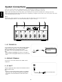
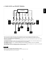
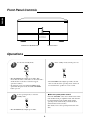
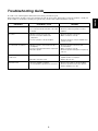
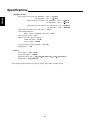
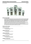
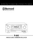
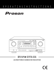
A-965
7-CH Power Amplifier
Introduction
ENGLISH
READ THIS BEFORE OPERATING YOUR UNIT
This symbol is intended to alert the user to the
presence of uninsulated "dangerous voltage"
within the product's enclosure that may be of
sufficient magnitude to constitute a risk of
electric shock to persons.
CAUTION
WARNING
: TO REDUCE THE RISK OF
ELECTRIC SHOCK, DO NOT
REMOVE COVER (OR BACK). NO
USER-SERVICEABLE PARTS
INSIDE. REFER SERVICING TO
QUALIFIED SERVICE PERSONNEL.
This symbol is intended to alert the user to the
presence of important operating and
maintenance (servicing) instructions in the
literature accompanying the appliance.
: TO REDUCE THE RISK OF FIRE OR ELECTRIC SHOCK,
DO NOT EXPOSE THIS APPLIANCE TO RAIN OR MOISTURE.
Caution regarding placement
To maintain proper ventilation, be sure to leave a space around the unit (from the largest outer
dimensions including projections)
equal to, or greater than, shown below.
Left and right panels : 10 cm
Rear panel : 10 cm
Top panel : 30 cm
Do not block ventilation openings or stack other equipment on the top.
FOR YOUR SAFETY
EUROPE
AUSTRALIA
220 V
240 V
Units shipped to Australia are designed for operation on 240 V AC only.
To ensure safe operation, the three-pin plug supplied must be inserted only into a
standard three-pin power point which is effectively earthed through the normal household
wiring. Extension cords used with the equipment must be three-core and be correctly
wired to provide connection to earth.
Improper extension cords are a major cause of fatalities. The fact that the equipment
operates satisfactorily does not imply that the power point is earthed and that the
installation is completely safe. For your safety, if in any doubt about the effective earthing
of the power point, consult a qualified electrician.
PAN-EUROPEAN UNIFIED VOLTAGE
All units are suitable for use on supplies 230~240 V AC.
•
•
•
•
•
•
•
•
Avoid high temperatures. Allow for sufficient heat dispersion when installed on a rack.
Keep the set free from moisture, water, and dust.
Do not let foreign objects in the set.
Handle the power cord carefully. Hold the plug when unplugging the cord.
Unplug the power cord when not using the set for long periods of time.
Do not obstruct the ventilation holes.
Do not let insecticides, benzene, and thinner come in contact with the set.
Never disassemble or modify the set in any way.
CAUTION
• The ventilation should not be impeded by covering the ventilation openings with items, such
as newspapers, table-cloths, curtains, etc.
• No naked flame sources, such as lighted candles, should be placed on the apparatus.
• Please be care the environmental aspects of battery disposal.
• The apparatus shall not be exposed to dripping or splashing for use.
• No objects filled with liquids, such as vases, shall be placed on the apparatus.
2
Introduction
READ THIS BEFORE OPERATING YOUR UNIT
System Connections
| 4
VARIOUS CONNECTIONS OF SPEAKER CORDS
SPEAKER PLACEMENT
Front Panel Controls
Operations
Specifications
| 7
| 8
| 8
Troubleshooting Guide
| 2
| 9
| 10
3
| 6
ENGLISH
CONTENTS
ENGLISH
System Connections
• Please be certain that this unit is unplugged from the AC outlet before making any connections.
• Be sure to observe the color coding when connecting the pre amplifier and speakers to this unit.
• Make connections firmly and correctly. If not, poor connections can cause loss of sound, noise or damage to the unit.
• For connections between this unit and the Sherwood compatible pre amplifier such as P-965, refer to the system connections
in the operating instructions of that.
Notes:
• Do not place other equipment on top of this unit so that the radiated heat can be properly dispersed.
• When installing in racks, etc., leave more than 30 cm(12˝) of space at the top.
GND
DC TRIGGER IN (12V)
MODEL NO. A-965
AC INPUT
230V~50Hz
1000W
7CH POWER AMPLIFIER
DESIGNED IN USA
ASSEMBLED IN KOREA
INPUT
FRONT RIGHT
(4-8 )
INPUT
INPUT
SURROUND
BACK RIGHT
(4-8 )
SURROUND
RIGHT(4-8 )
INPUT
CENTER(4-8
)
INPUT
SURROUND
LEFT(4-8 )
INPUT
SURROUND
BACK LEFT
(4-8 )
INPUT
FRONT LEFT(4-8
)
1. DC TRIGGER IN
In case that this unit is connected to Sherwood pre amplifier
P-965, connect this jack to the “1” jack of DC TRIGGER
OUTs of P-965 directly for system power control.
(For details, refer to the operating instructions of P-965.)
Note:
• When making DC TRIGGER connection, you should use
the stereo mini cord supplied with this unit, not a mono mini
cord.
Sherwood pre amplifier P-965
1
2
DC TRIGGER OUT
2. GROUND TERMINAL
If necessary, connect this terminal to the “GND” of other
component.
3. AC INLET
Plug the supplied AC input cord into this AC INLET and then
into the wall AC outlet.
Note:
• Do not use an AC input cord other than the one supplied
with this unit. The AC input cord supplied is designed for
use with this unit and should not be used with any other
device.
To a wall AC outlet.
4
ENGLISH
4. CHANEL INPUTs and SPEAKER TERMINALs
Front right
INPUT
FRONT RIGHT
(4-8 )
INPUT
INPUT
SURROUND
BACK RIGHT
(4-8 )
SURROUND
RIGHT(4-8 )
INPUT
CENTER(4-8
)
Front left pre out
Surround back
left pre out
Surround
left pre out
Center pre out
Surround right
pre out
Surround back
right pre out
Front right pre out
Pre amplifier
INPUT
INPUT
SURROUND
BACK LEFT
(4-8 )
SURROUND
LEFT(4-8 )
Front left
INPUT
FRONT LEFT(4-8
)
Center
Surround
right
Surround
left
Surround
back right
Surround
back left
• Be sure to connect speakers firmly and correctly according to the channel (left and right) and the polarity(+ and -).
If the connections are faulty, no sound will be heard from the speakers, and if the polarity of the speaker connections is
incorrect, the sound will be unnatural and lack bass.
• Only when enjoying either 6.1 or 7.1 channel surround playback, connect either the surround back left speaker only or both of
surround back speakers.
• To emphasize the deep bass sounds, connect a powered subwoofer to the pre amplifier such as Sherwood P-965 not to this
power amplifier. (For details, refer to the operating instructions of the pre amplifier.)
• For installing the speakers, refer to “VARIOUS CONNECTIONS OF SPEAKER CORDS” on page 6 and “SPEAKER
PLACEMENT” on page 7.
• After installing the speakers, first adjust the speaker settings on your pre amplifier according to your environment and speaker
layout.(For details, refer to the operating instructions of the pre amplifier.)
CAUTION
• Be sure to use the speakers with the impedance of 4~8Ω.
• Do not let the bare speaker wires touch each other or any metal part of this unit.
This could damage this unit and / or the speakers.
5
ENGLISH
VARIOUS CONNECTIONS OF SPEAKER CORDS
General connection using the bare
cords
Connection using the spade plugs
1. Carefully strip about 10 mm(3/8˝) of insulation and
twist the wire tip.
1. Loosen the knob and insert the spade plug.
2. Loosen the knob and insert the wire.
2. Tighten the knob to fix.
3. Tighten the knob to fix the wire in place.
Connection using the banana plugs
1. Tighten the knob.
2. Insert the plug fully into the hole on the knob.
6
Ideal speaker placement varies depending on the size of your room
and the wall coverings, etc. The typical example of speaker
placement and recommendations are as follows :
ENGLISH
SPEAKER PLACEMENT
1
3
2
4
5
■Front left and right speakers and center speaker
• Place the front speakers with their front surfaces as flush with TV or
monitor screen as possible.
• Place the center speaker between the front left and right speakers
and no further from the listening position than the front speakers.
• Place each speaker so that sound is aimed at the location of the
listener’s ears when at the main listening position.
6
7
11
■Surround left and right speakers
• Place the surround speakers approximately 1 meter(40 inches)
above the ear level of a seated listener on the direct left and right of
them or slightly behind.
8
10
9
■Surround back left and right speakers
• Place the surround back speakers at the back facing the front at a
narrower distance than the front speakers.
• When using a single surround back speaker, place it at the rear
center facing the front at a slightly higher position(0 to 10 inches)
than the surround speakers.
• We recommend installing the surround back speaker at a slightly
downward facing angle. This effectively prevents the surround back
channel signals from reflecting off the TV or screen at the front
center, resulting in interference and making the sense of movement
from the front to the back less sharp.
■Subwoofer
1. TV or screen
2. Front left speaker
3. Subwoofer
4. Center speaker
5. Front right speaker
6. Surround left speaker
Surround speaker
7. Surround right speaker
8. Surround back left speaker
9. Surround back right speaker
10. Surround back center speaker
11. Listeing position
Surround back
speaker
Point slightly
downward
Front speaker
• The subwoofer reproduces powerful deep bass sounds.
Place a subwoofer anywhere in the front as desired.
60 to 90 cm
■Notes :
• When using a conventional TV , to avoid interference with the TV
picture, use only magnetically shielded front left and right and center
speakers.
• To obtain the best surround effects, the speakers except the
subwoofer should be full range speakers.
7
ENGLISH
Front Panel Controls
W R A S
WIDE RANGE AMPLIFIER STAGE
STANDBY BUTTON/INDICATOR
POWER SWITCH
Operations
1
To enter the standby mode.
2
• The STANDBY button lights up in amber. This
means that the unit is connected to an AC outlet and a
small amount of current is retained to support
operation readiness.
• To switch the power off, push the POWER switch
again. Then the power is cut off and the STANDBY
button goes off.
3
In the standby mode, turn the power on.
• The STANDBY button lights up in blue, the unit
turns on and enters the operating mode. Sound can
be heard from the speakers in a few seconds.
In the operating mode, to enter the
standby mode.
Note on system power control
If the DC TRIGGER connection is made between this
unit and Sherwood pre amplifier P-965, this unit will
be switched between the standby mode and the
operating mode automatically each time P-965 is
switched between these modes.
(For details, refer to the operating instructions of P965.)
• The STANDBY button lights up in amber.
8
If a fault occurs, run through the table below before taking your unit for repair.
If the fault persists, attempt to solve it by switching the unit off and on again. If this fails to resolve the situation, consult your
dealer. Under no circumstances should you repair the unit yourself as this could invalidate the warranty!
PROBLEM
POSSIBLE CAUSE
REMEDY
No power
• The AC input cord is disconnected.
• Poor connection at AC wall outlet or the outlet
is inactive.
• Connect the cord securely.
• Check the outlet using a lamp or another
appliance.
No sound
• Speaker cords are disconnected.
• Incorrect connections between the
components.
• Incorrect operation of the pre amplifier.
• Check the speaker connections.
• Make connections correctly.
No sound from one channel
• Speaker cords are connected incorrectly or
incompletely.
• Incorrect connections between the components.
• Defective speaker.
• Check the speaker connections and
reconnect them.
• Make connections correctly.
• Check the speaker and repair it or replace by
new one.
Excessive hum at normal
volume level
• The hum is induced from other components.
• Place the power amplifier away from the pre
amplifier and the record player.
• Replace by new ones.
• Defective connection cords.
Distorted sound
• The power amplifier overdriven.
• Too low impedance speakers are connected.
9
• Check the functions of the pre amplifier and
operate correctly.
• Decrease the volume on the pre amplifier.
• Check the speakers and use the speakers
with the impedance of 4~8Ω.
ENGLISH
Troubleshooting Guide
Specifications
ENGLISH
• Amplifier Section
×125 W
Power output, stereo mode, 8 Ω, THD 0.02 %, 1 kHz | 2×
×170 W
4 Ω, THD 0.02 %, 1 kHz | 2×
×100 W
7-CH mode(full channel driven), 8 Ω, THD 0.02 %, 1 kHz | 7×
×150 W
4 Ω, THD 0.02 %, 1 kHz | 7×
7-CH mode(only channel driven), 8 Ω, THD 0.02 %, 1 kHz | 130 W/CH
4 Ω, THD 0.02 %, 1 kHz | 200 W/CH
Total harmonic distortion, 8 Ω, 125 W, 1 kHz | 0.02 %
Intermodulation distortion
60 Hz : 7 kHz= 4 : 1 SMPTE, 8 Ω, 125 W | 0.01 %
Input sensitivity, 47 kΩ | 1.0 V
Signal to noise ratio, IHF “A” weighted
100 W, 8 Ω, 0 dB | 115 dB
1 W, 8 Ω, 0 dB | 100 dB
Frequency response, 20 Hz~100 kHz | +0, -1 dB
Damping factor | 100
• General
Power supply | 230 V ~ 50 Hz
Power consumption | 1000 W
×196×
×450 mm(17-3/8×
×7-3/4×
×17-3/4 inches )
Dimensions (W×H×D) | 440×
Weight (Net) | 32 kg (70.6 Ibs)
Note: Design and specifications are subject to change without notice for improvements.
10
A-965
7-CH Power Amplifier
5707-04746-002-0